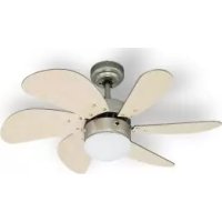
DC30T - Fan BESTRON - Free user manual and instructions
Find the device manual for free DC30T BESTRON in PDF.


| Product type | Ceiling fan |
| Brand | Bestron |
| Model | DC30T |
| Number of blades | 6 reversible blades (white or wood side) |
| Speeds | 3 speeds (fast, medium, slow) by pull chain |
| Operating modes | Summer mode (downward airflow) and winter mode (warm air circulation) |
| Built-in lighting | E14 socket, 60 W max bulb (not supplied) |
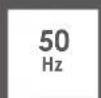
| Power supply | 220-240 V ~ 50 Hz |
| Minimum mounting height | 2.30 m between blades and floor |
| Weight supported by mounting plate | Minimum 23 kg |
| Downrod length | Standard (not specified, possible to mount without downrod for low ceilings) |
| Rotation direction | Reversible (summer/winter switch) |
| Noise level | Quiet (slight trembling possible) |
| Balancing kit supplied | 2 balancing weights and 1 balancing clip |
| Warranty | 60 months (5 years) on manufacturing defects |
| Maintenance | Clean with a soft, dry cloth; do not immerse |
| Safety | Automatic shut-off in case of overheating (not mentioned, but standard) |
| Materials | Metal motor, wood or composite blades, glass for lampshade |
| Dimensions (diameter) | Approximately 132 cm (estimate for 6 blades) |
| Net weight | Approximately 6 kg (estimate) |
Frequently Asked Questions - DC30T BESTRON
User questions about DC30T BESTRON
0 question about this device. Answer the ones you know or ask your own.
Ask a new question about this device
Download the instructions for your Fan in PDF format for free! Find your manual DC30T - BESTRON and take your electronic device back in hand. On this page are published all the documents necessary for the use of your device. DC30T by BESTRON.
USER MANUAL DC30T BESTRON
natural_image
Top-down view of a wooden and wood propeller fan with visible blades and a brand logo (no text or symbols on the fan itself)


DC30T INSTRUCTION MANUAL
DE
Bedienungsanleitung
FR
Mode d'emploi
NL
Handleiding
EN
Instruction manual
IT
R. Neyman
Quality control
FUNKTION - Allgemein
natural_image
Simple line drawing of a mechanical component inside an oval frame, labeled 'F' at bottom (no text or symbols on the diagram itself)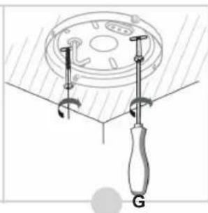
natural_image
Diagram of a screwdriver tool securing a circular component with a handle, labeled 'G' (no text or symbols on the diagram itself)
natural_image
Two technical diagrams showing a mechanical assembly with labeled parts O and P, no readable text or symbols present.natural_image
Technical illustration showing a mechanical assembly before and after disassembly, with no visible text or symbols.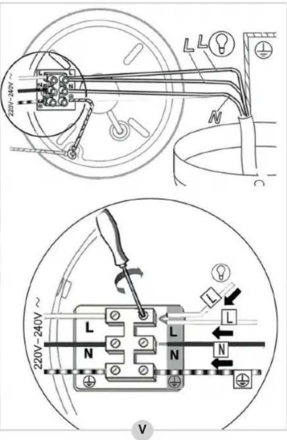
flowchart
graph TD
    A["1: Top panel with internal components"] --> B["2: Top panel with light bulb"]
    B --> C["3: Top panel with light bulb inside lamp"]
    C --> D["4: Top panel with light bulb inside lamp"]
    D --> E["5: Top panel with light bulb inside lamp"]
    E --> F["6: Top panel with light bulb inside lamp"]
natural_image
Line drawing of a ceiling fan with visible blades, screwdriver, and bulb (no text or symbols)FEHLERBEHEBUNG
flowchart
graph TD
    A["Step A: Air fan rotation with X_NO"] --> B["Step B: Air fan with ✓OK"]
    B --> C["Step C: Air fan with ✓OK"]
DÉCLARATION DE CONFORMITÉ CE
natural_image
Pure electrical circuit lines without any symbols
natural_image
Diagram of a screwdriver holding a circular component with a handle, no text or symbols present
natural_image
Technical illustration showing a mechanical assembly before and after modification, with no visible text or symbols.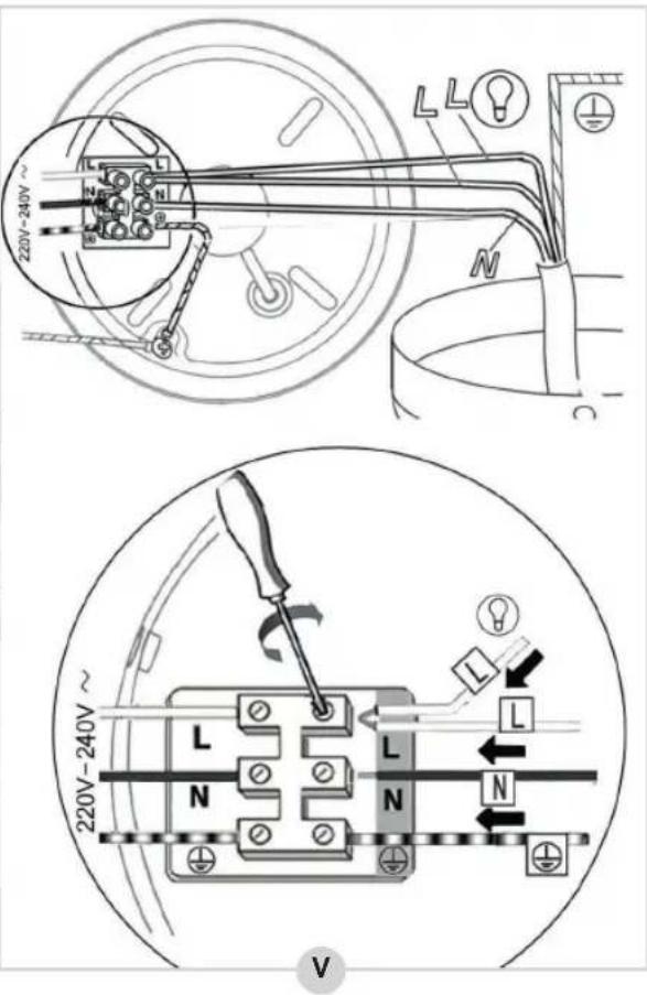
flowchart
graph TD
    A["1: Top panel with internal components"] --> B["2: Top panel with light bulb"]
    B --> C["3: Top panel with light bulb inside top panel"]
    C --> D["4: Top panel with light bulb inside bottom panel"]
    D --> E["5: Top panel with light bulb inside bottom panel"]
    E --> F["6: Top panel with light bulb inside top panel"]
    F --> G["7: Top panel with light bulb inside bottom panel"]
natural_image
Line drawing of a ceiling fan with visible blades, screwdriver, and bulb (no text or symbols)SOLUTIONS AUX PROBLÈMES
flowchart
graph TD
    A["A"] --> B["X_NO"]
    B --> C["Step B: fan rotation with checkmark OK"]
    C --> D["Step C: fan rotation with checkmark OK"]
WAT U MOET WETEN OVER DIT APPARAAT
R. Neyman
Quality control
WERKING - Algemeen
natural_image
Simple line drawing of a mechanical component with no text or symbols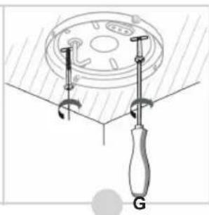
natural_image
Diagram of a screwdriver tool securing a circular component with a handle, labeled 'G' (no text or symbols on the diagram itself)
natural_image
Two technical diagrams showing a mechanical assembly with labeled parts O and P, no readable text or symbols present.natural_image
Technical illustration showing a mechanical assembly before and after disassembly, with no visible text or symbols.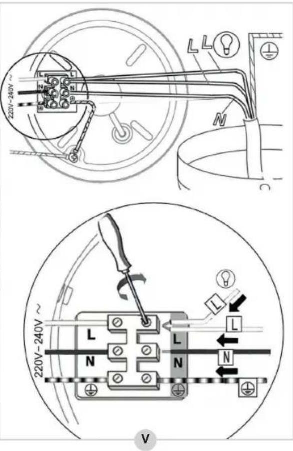
flowchart
graph TD
    A["1: Top panel with internal components"] --> B["2: Left panel with upper control"]
    B --> C["3: Right panel with upper control"]
    C --> D["4: Bottom panel with lower control"]
    D --> E["5: Down panel with upper control"]
    E --> F["6: Left panel with upper control"]
    F --> G["7: Right panel with lower control"]
natural_image
Line drawing of a ceiling fan with a light bulb and hanging blades (no text or symbols)GEBRUIK - Zomer- en winterstand
PROBLEMEN OPLOSSEN
flowchart
graph TD
    A["Step A: Air fan rotation with X_NO"] --> B["Step B: Air fan rotation with ✓ OK"]
    B --> C["Step C: Air fan rotation with ✓ OK"]
Congratulations with the purchase of this Bestron product. These instructions tell you how the product works and how to use it. Read the instructions carefully before you start using the appliance. Only use the appliance in the manner described in the instructions. Keep these instructions in a safe place for future reference.
Defects:
If the appliance is defective, do not try to repair it yourself. Always have a qualified mechanic carry out any repairs.
Children:
- This appliance may be used by children over the age of 8 years old and persons with reduced physical, sensory or mental capabilities or lack of experience and know-how, but only if supervised or if they have been instructed on how to use the appliance safely and are aware of its potential dangers.
• Children are not allowed to clean and maintain the appliance, except if they are over the age of 8 years old and supervised. - Keep the appliance and the cable out of reach of children under the age of 8 years old.
- Keep an eye on children to ensure that they do not play with the appliance.
WHAT YOU SHOULD KNOW ABOUT ELECTRICAL APPLIANCES
- Check that the mains voltage corresponds with that shown on the rating plate of an electrical appliance before you use it.
- Check that the socket to which you connect the electrical appliance is earthed.
• Always install electrical appliances on a stable and level surface where it cannot fall over.
• Certain parts of an electrical appliance may become warm or sometimes hot. Do not touch them as you may burn yourself.
• Make sure your hands are dry when you touch an electrical appliance, a cord or a plug. - Electrical appliances must be able to lose their heat to avoid fire hazards. Therefore, make sure that the appliance has sufficient clearance around it and that it does not come into contact with flammable materials. Electrical appliances must never be covered.
-
Make sure that electrical appliances, cords or plugs do not come into contact with water.
-
Never immerse electrical appliances, cords or plugs in water or any other liquid.
- Do not touch electrical appliances if they have fallen in the water. Immediately pull the plug out of the socket. Stop using the appliance.
• Make sure that electrical appliances, cords and plugs do not come into contact with heat sources, such as a hot hob or open fire. - Never let cords hang over the edge of the sink, a worktop or a table.
• Always remove plug from the socket when you are not using the electrical appliance. - Remove the plug from the socket by pulling the plug itself and not the cord.
- Regularly check if the cord of the electrical appliance is not damaged. Do not use the electrical appliance if the cord shows signs of damage. If the cord is damaged, it should be replaced by the manufacturer, a technical service provider or a person with an equivalent qualification, to avoid any danger.
- The appliance may not be switched on with the aid of an external time switch, or by a separate system with remote control.
WHAT YOU SHOULD KNOW ABOUT THIS APPLIANCE
• Be careful when using the appliance outdoors.
• Never use the appliance in damp or wet locations.
- Thoroughly clean the appliance after use (see Cleaning and Maintenance).
• We recommend the installation be performed by a qualified electrician who can check the strength of the supportive ceiling members and make proper electrical connection.
• To reduce the risk of personal injury, use only the two steel screws (and lock washer) provided for mounting.
- To reduce the risk of personal injury, do not bend the blade holders when installing the holders, balancing the blades or cleaning the fan.
ENVIRONMENT
- Dispose of packaging material such as plastic and cardboard boxes in the designated containers.
Do not dispose of this product as normal domestic waste at the end of its life, but hand it in at a collection point for the reuse of electric and electronic equipment. Look for the symbol on the product, the user instructions or the packaging showing the type of waste.
- The materials can be used as indicated. By helping us reuse and process the materials or otherwise recycle the old equipment, you will be making an important contribution towards the protection of the environment.
- Your municipality can tell you where to find the designated waste collection point in your neighbourhood.
CE DECLARATION OF CONFORMITY
This product conforms to the requirements of the following European Directives on safety:
• EMC Directive 2014/30/EU
• Low Voltage Directive 2014/35/EU
• RoHS Directive 2011/65/EU
R. Neyman
Quality control
OPERATION - General
The appliance is intended only for domestic use, not for professional use.
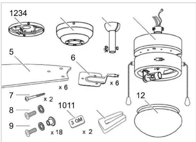
- Mounting plate
- Canopy
- Down rod
- Motor
- Fan blades (6x)
- Fan blade holder (6x)
- Screws mounting plate (2x)
- Screw set canopy (3x)
- Screw set fan blades (18x)
- Balance weight (2x)
- Balance clamp
- Glass lamp cover
MONTAGE - Installing the mouting plate
WARNING:
• ALWAYS SWITCH OFF THE MAINS POWER BEFORE INSTALLING OR CARYING OUT ANY WORK ON THE CEILING FAN.
- Be sure to hang the fan in a place where the distance between the fan blades and the floor will be at least 2.30m.
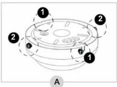
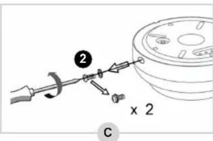
- In the packaging the mounting plate is already assembled to the canopy by four screws (see figure A).
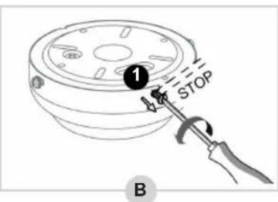
- Loosen the two screws ① halfway (B).
- Unscrew the two screws ② completely and remove them (C).

natural_image
Pure diagram of a mechanical or electrical component with no visible text, numbers, or symbols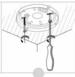
natural_image
Technical diagram of a mechanical clamp or fixture with a circular component and a handle (no text or symbols)
-
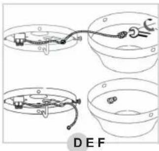
Remove the mounting plate from the canopy and unscrew the yellow-green earth wire from the canopy (D).
-
Lead the wires emerging from your ceiling through the opening in the mounting plate (E).
-
Screw the mounting plate to the ceiling (F). Make sure the mounting plate is mounted firmly enough to hold a minimum weight of 23 kg (51 lb).
-
Now connect the wires to the terminal block on the mounting plate in the following way (G):
-
Blue wire → N
• Brown or black wire → L
• Earth wire (yellow-green) → ⏚
MONTAGE - Installing the down rod onto the motor (option 1)
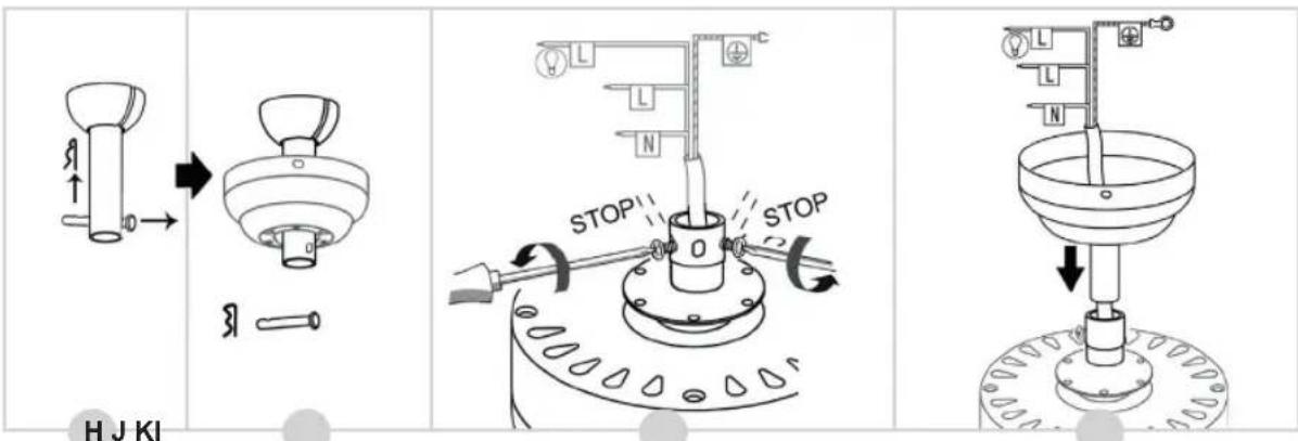
- Remove the cotter pin and metal pin from the down rod (see figure H).
- Lead the down rod through the canopy (I).
- Untighten the two screws on the motor (J).
- Remove the cable binder from around the wiring and lead the wires through the down rod (K). Make sure not to damage the wiring in the process.
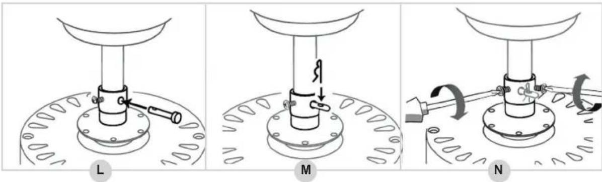
- Reinstall the metal pin into the down rod (L) en secure it by reinsterting the cottor pin (M).
- Tighten the two screws on the motor (N).
The down rod has now been installed correctly.
MONTAGE - Installing the canopy directly onto the motor (option 2)
This ceiling fan type offers the possibility of installing the canopy directly onto the motor housing, without using the down rod. This can be useful, for example, when installing the fan in low ceiling areas. Please note that choosing this option may affect the air circulation.

natural_image
Two technical diagrams showing a mechanical assembly with labeled parts O and P, no readable text or symbols present.- The motor housing is equipped with a mounting ring. Insert the wiring through the canopy and place the canopy on the mounting ring so that the holes in the canopy fit with the screw holes in the mounting ring (see figure O).
- Take the 3 screws and spring rings (No. 8 in the figure under 'OPERATION - General') and firmly tighten the canopy to the motor housing (P).
The canopy has now been installed correctly to the motor house.
natural_image
Technical illustration showing a mechanical assembly before and after disassembly, with no visible text or symbols.The fan blades of this ceiling fan are asymmetrical in shape. Although the blades can be installed both with the white as the wood-colored side pointed downwards, it is recommended to point the wood-colored side downwards. Pointing the white side downwards can affect the air circulation due to the reverse shape of the fan blades.
- Take a fan blade holder and place it onto a fan blade as shown in figure Q.
- Insert a screw with a red ring through the fan blade holder and fan blade.
- Place a cap nut under the fan blade, then tighten the screw into the cup nut.
MONTAGE - Installing the fan blades onto the motor
- The screws for installing the fan blades have already been screwed into the motor housing. Unscrew them and remove them from the motor housing (see figure R).
- Take a fan blade with fan blade holder and screw it to the motor housing using two screws (S).
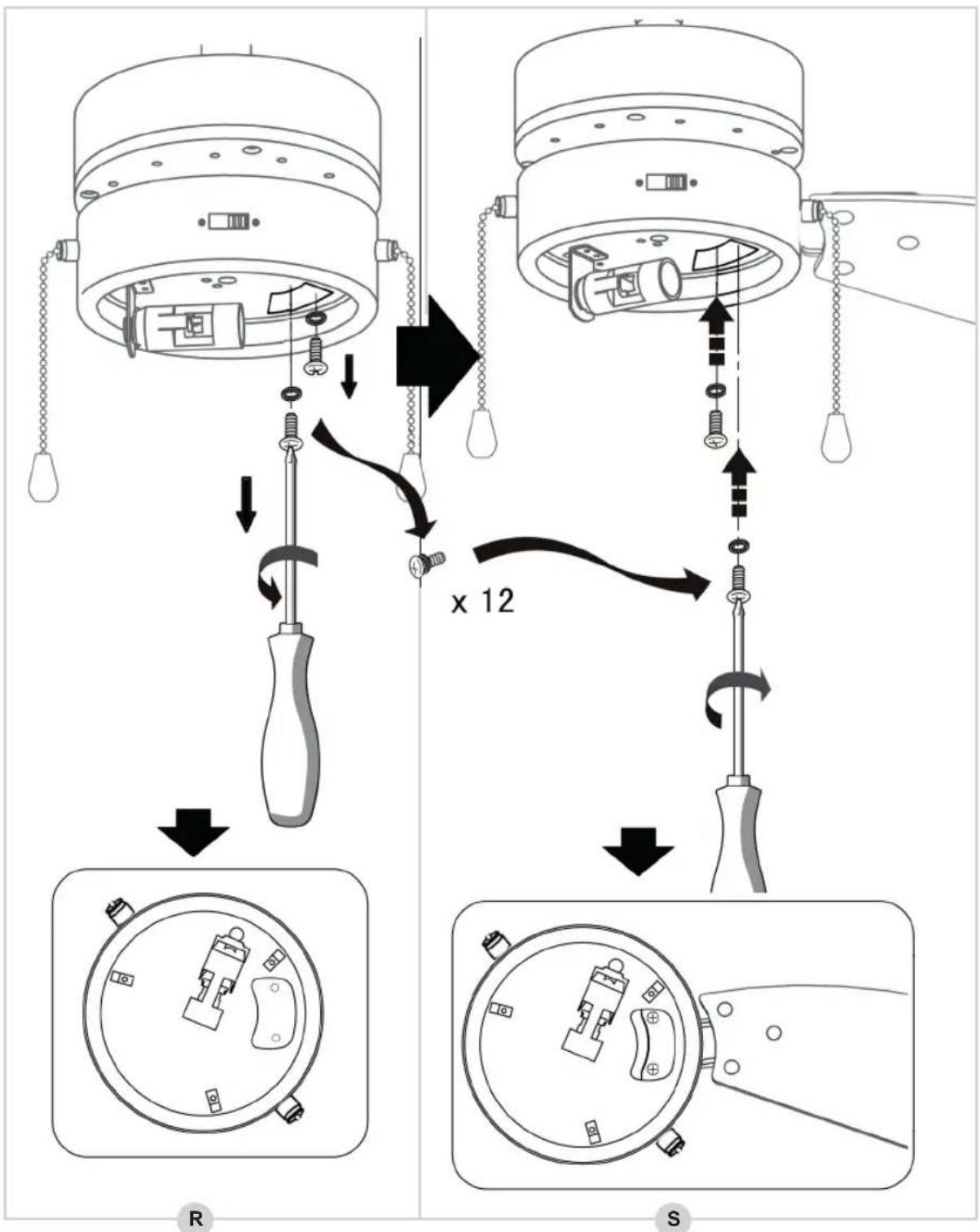
- Repeat the process for the other five fan blades.
The fan blades have now been installed correctly.
MONTAGE - Installing the fan to the mounting plate
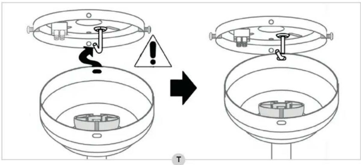
- Lift up the fan and insert the "J-hook" on the mounting plate through one of the openings in the canopy (see figure T). This will leave your hands free for connecting the fan's wiring.
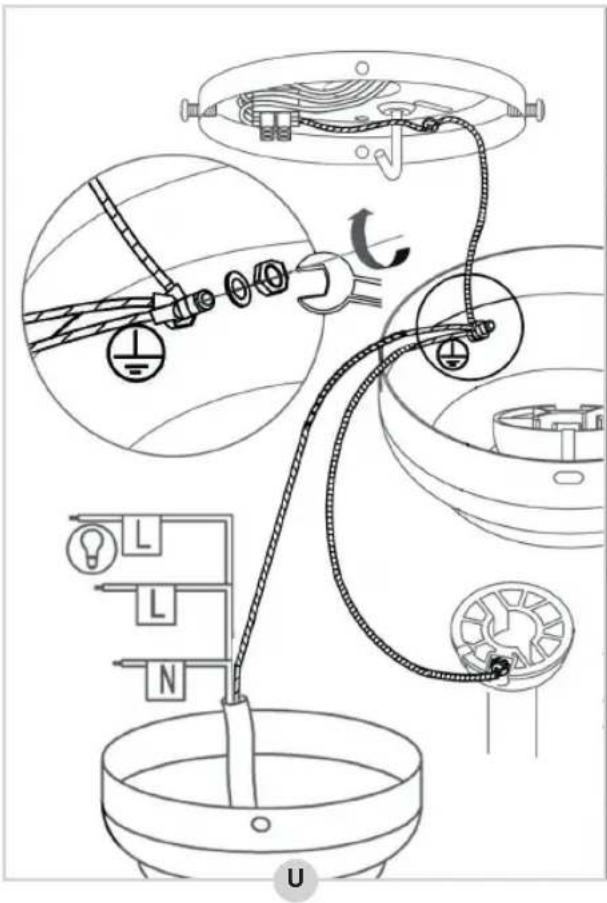
- Connect all earth wires (yellow-green) to the canopy (U).
-
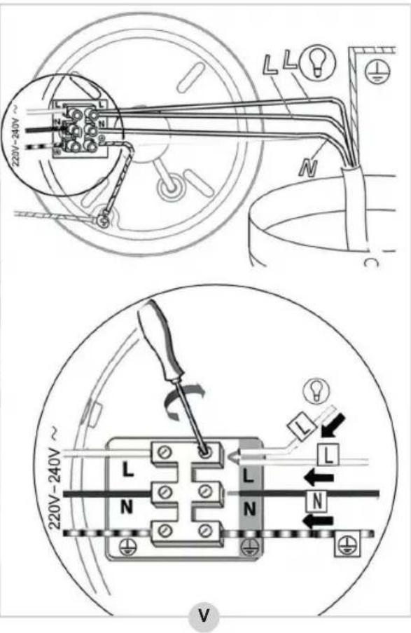
Connect the wiring coming from the down rod to the terminal block on the mounting plate in the following way (V):
-
Blue wire → N
• Brown and black wires → L

flowchart
graph TD
    A["1: Top panel with internal components"] --> B["2: Top panel with light bulb"]
    B --> C["3: Top panel with light bulb inside lamp"]
    C --> D["4: Top panel with light bulb inside lamp"]
    D --> E["5: Top panel with light bulb inside lamp"]
    E --> F["6: Top panel with light bulb inside lamp"]
- Now lift the fan from the "J-hook", place the fan over the two screws ① in the mounting plate and tighten the screws firmly (W).
- Insert the two screws ② into the mounting plate and tighten them firmly as well (W).
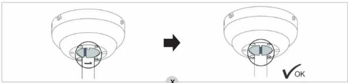
- Secure the down rod as depicted in figure X.
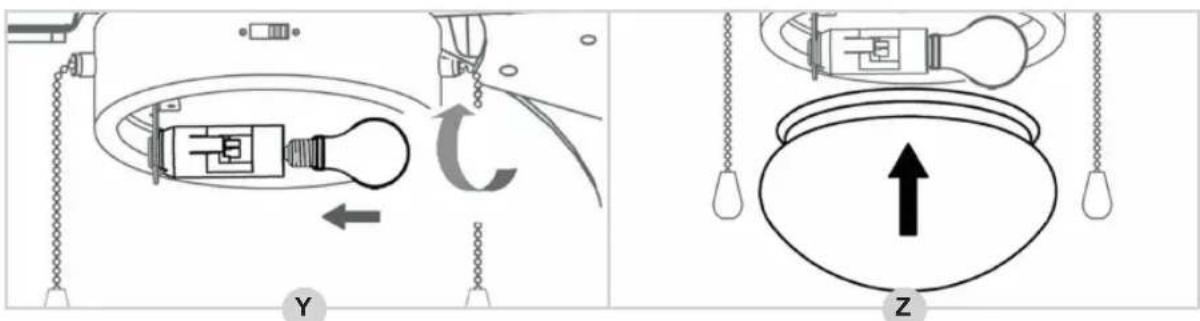
- Now, place a lamp type E14 (60 Watts max.) in the lamp socket (see figure Y).
- Carefully place the glass lamp cover over the three brackets (Z).
The fan has now been installed correctly.
You can now switch the mains power back on.
The ceiling fan has 3 speeds: fast, medium and slow.
- Pull the pull chain.
The fan will start at fast speed. - Pull the pull chain again.
The fan speed will change to medium. - Pull the pull chain again.
The fan speed will change to slow. - Pull the pull chain again.
The fan will shut off.

natural_image
Line drawing of a ceiling fan with a light bulb and three blades, no text or symbols presentOPERATION - Summer/winter mode
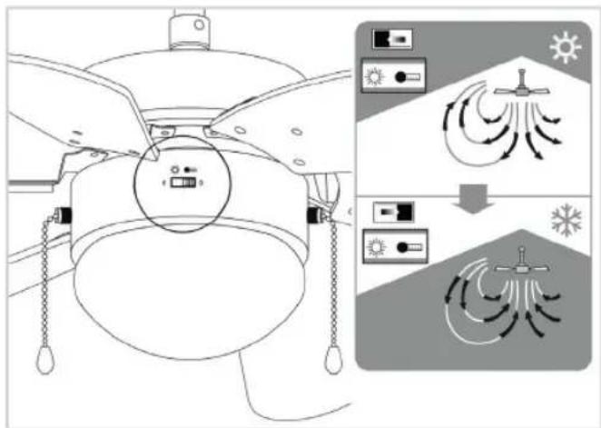
The ceiling fan is equipped with a summer mode and a winter mode: in summer mode the fan will blow air directly down, creating a cool breeze, while in winter mode the fan will circulate the air warmed by your heating system through the room.
- Switch the mode switch to the left to use the summer mode.
- Switch the mode switch to the right to use the winter mode.
TROUBLESHOOTING
| Trouble Probable Cause Suggested Remedy | ||
| Fan will not start | 1. The fan is connected to a light switch which has been turned off.2. Fuse or circuit breaker blown or mains power not switched back on.3. Loose power line connections to the fan. | 1. Check whether the light switch has been turned on.2. Check whether the mains power has been switched on.3. Check line wire connections to fan and switch wire connections in switch housing.CAUTION: Make sure main power is turned off. |
| Fan sounds noisy.Fan wobbles or shakes excessively. | 1. Mounting plate hasn’t been installed correctly.2. The down rod hasn’t been secured properly. | 1. Check to make sure the mounting plate is (still) firmly attached to the ceiling. See ‘Montage - Installing the mouting plate’.2. Check to make sure the down rod has been secured properly. See ‘Montage - Installing the down rod to the motor’. |
TROUBLESHOOTING - Balancing the fan blades
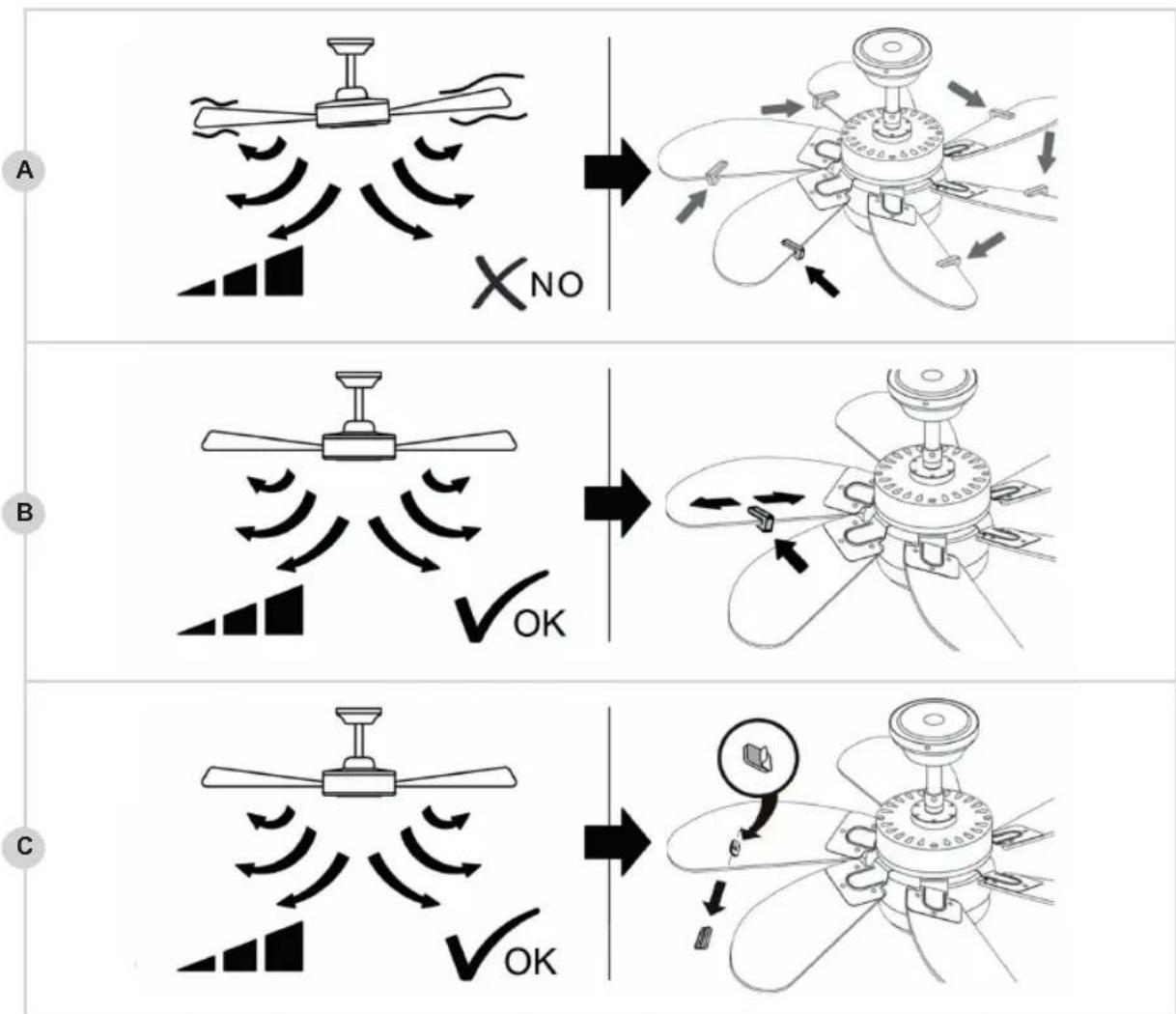
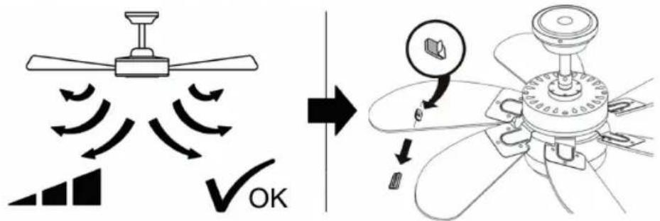
We do our utmost to ensure that your fan is of the highest quality. Nevertheless, it may sometimes be out of balance. If the fan is unstable or shaking excessively, first follow the steps under 'TROUBLESHOOTING'. If the fan persists to shake excessively, try to exchange two opposing fan blades and turn on the fan. If after this operation the fan still persists to shake, please use the balancing set:
flowchart
graph TD
    A["Step A: Air fan rotation with X_NO"] --> B["Step B: Air fan with ✓OK"]
    B --> C["Step C: Air fan with ✓OK"]
- Turn on the fan and find the speed at which the shaking is the worst. Turn off the fan.
- Select one of the fan blades and place the balancing clamp halfway the straight side of the blade (see figure A). Turn the fan back to the speed at which the shaking was the worst. Check whether the shaking has become less. Turn off the fan.
- Repeat this procedure with each remaining blade and check which blade shows the most improvement.
- Place the balancing clamp on the fan blade where you found the most improvement once more and push the clamp inward or outward onto the blade (B). Turn the fan back to the speed at which the shaking was the worst. Check whether the shaking has become less. Turn off the fan.
- Repeat this procedure and check at which position of the balance clamp you see the most improvement.
- Remove the balancing clamp and paste one of the two balance weights on the fan blade where you found most improvement, exactly on the spot where the balancing clamp was located (C).
Please note that all ceiling fans can continue to shake very lightly.
WARRANTY CONDITIONS
Bestron offers a 60-month warranty on this equipment against defects resulting from manufacturing and/or material errors, subject to the following conditions.
-
No labour or material costs will be charged during this warranty period.
-
Any repairs carried out under the warranty will not extend the warranty period.
-
Faulty parts, or in the event of exchange, the faulty equipment itself, will automatically become the property of Bestron.
-
The warranty is valid for the first buyer only and is non-transferable.
-
The warranty is not valid for damage caused by:
-
Accidents
- Improper use
- Wear and tear
- Neglect
- Faulty installation
-
Connection to a different mains voltage than indicated on the type plate
• Unauthorised changes
• Repairs carried out by unqualified third parties
• Use in violation with the applicable statutory, technical or safety standards
• Careless transport without suitable packaging or other protection -
Warranty cannot be claimed:
• For damage during transport
• If the serial number of the appliance is removed or changed
- Items excluded from warranty are:
Cords
- Lamps
- Glass parts
-
The warranty does not entitle the purchaser to compensation for any damage other than replacement or repair of the faulty parts. Bestron cannot in any event be held liable for any indirect or consequential losses caused by or in relation to the equipment it has provided.
-
Claims under a warranty may only be submitted to your (online) retailer or directly to the Bestron Service Department. Never send items without being asked to. We may refuse the parcel and you will be liable for the costs. Contact us first and we tell you how the appliance should be packaged and sent. Each claim under a warranty must be accompanied by the relevant receipt.
SERVICE
If an unexpected problem occurs, please contact the BESTRON service department: www.bestron.com/service
COMPLIMENTI!
R. Neyman
Controllo qualità
natural_image
Diagram showing three stages of a medical procedure: catheter insertion, endoscopic view, and final bowl with tubing (no text or labels)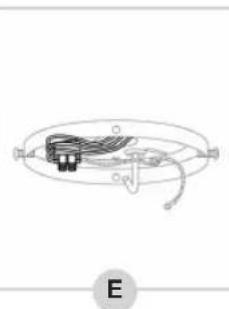
natural_image
Pure electrical circuit lines without any symbols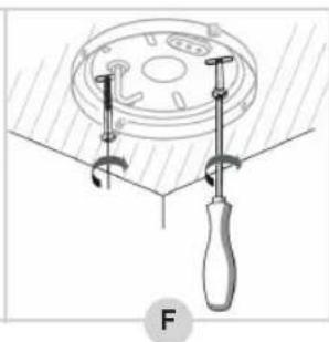
natural_image
Diagram of a mechanical clamp or fixture with a circular component and a tool, no text or symbols present.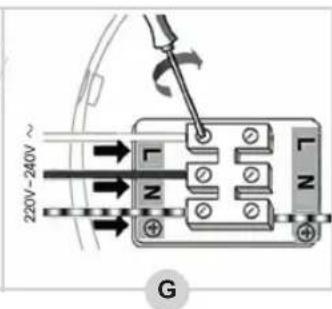
natural_image
Two technical diagrams showing a mechanical assembly with a central component and two views labeled O and P, no text or symbols present.natural_image
Technical illustration showing a mechanical assembly before and after modification, with no visible text or symbols.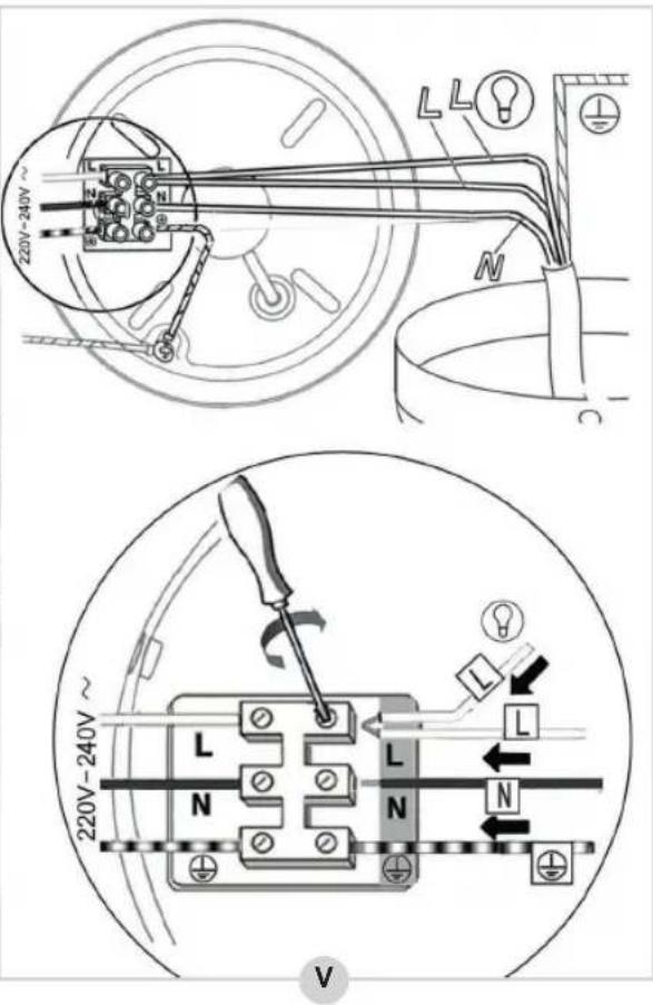
flowchart
graph TD
    A["1: Top panel with internal components"] --> B["2: Top panel with light bulb"]
    B --> C["3: Top panel with light bulb inside lamp"]
    C --> D["4: Top panel with light bulb inside lamp"]
    D --> E["5: Top panel with light bulb inside lamp"]
    E --> F["6: Top panel with light bulb inside lamp"]
natural_image
Line drawing of a ceiling fan with a light bulb and three blades, no text or symbols presentflowchart
graph TD
    A["Step A: Air fan rotation with X_NO"] --> B["Step B: Air fan with ✓OK"]
    B --> C["Step C: Air fan with ✓OK"]
R. Neyman
Control de calidad
USO - General
natural_image
Diagram showing three stages of a medical procedure: catheter insertion, surgical tool placement, and endoscopic view (no text or labels)
natural_image
Pure electrical circuit lines without any symbols
natural_image
Diagram of a mechanical clamp or fixture with a circular component and a handle, no text or symbols present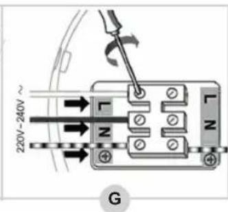
natural_image
Two technical diagrams showing a mechanical assembly with labeled parts O and P, no readable text or symbols present.natural_image
Technical illustration showing a mechanical assembly before and after disassembly, with no visible text or symbols.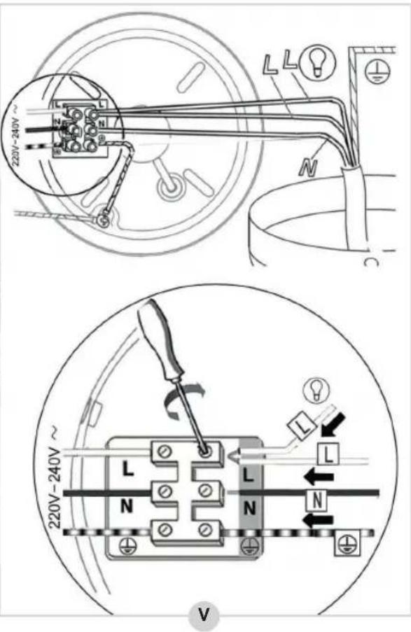
flowchart
graph TD
    A["1: Top panel with internal components"] --> B["2: Left panel with upper control"]
    B --> C["3: Right panel with upper control"]
    C --> D["4: Bottom panel with lower control"]
    D --> E["5: Down panel with upper control"]
    E --> F["6: Left panel with upper control"]
    F --> G["7: Right panel with lower control"]
natural_image
Line drawing of a ceiling fan with visible blades, screw, and indicator lights (no text or symbols)C
NEED HELP? CHAT WITH US! WHATSAPP CUSTOMER SERVICE

BESTRON.COM/WHATSAPP
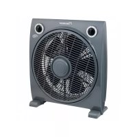
- DC30T INSTRUCTION MANUAL
- FUNKTION - Allgemein
- FEHLERBEHEBUNG
- DÉCLARATION DE CONFORMITÉ CE
- SOLUTIONS AUX PROBLÈMES
- WAT U MOET WETEN OVER DIT APPARAAT
- WERKING - Algemeen
- GEBRUIK - Zomer- en winterstand
- PROBLEMEN OPLOSSEN
- Defects:
- Children:
- WHAT YOU SHOULD KNOW ABOUT ELECTRICAL APPLIANCES
- WHAT YOU SHOULD KNOW ABOUT THIS APPLIANCE
- ENVIRONMENT
- CE DECLARATION OF CONFORMITY
- OPERATION - General
- MONTAGE - Installing the mouting plate
- WARNING:
- MONTAGE - Installing the down rod onto the motor (option 1)
- MONTAGE - Installing the canopy directly onto the motor (option 2)
- MONTAGE - Installing the fan blades onto the motor
- OPERATION - Summer/winter mode
- TROUBLESHOOTING
- TROUBLESHOOTING - Balancing the fan blades
- WARRANTY CONDITIONS
- SERVICE
- COMPLIMENTI!
- USO - General
Brand : BESTRON
Model : DC30T
Category : Fan