Mixage Interface Edition MK2 - Mixer Reloop - Free user manual and instructions
Find the device manual for free Mixage Interface Edition MK2 Reloop in PDF.

| Product type | 4-deck professional MIDI controller with integrated audio interface |
| Dimensions | 370 x 61 x 266 mm |
| Weight | 2.4 kg |
| Power supply | USB (5V, bus-powered) |
| Number of decks managed | 4 (via software) |
| Integrated audio interface | Yes, with ASIO drivers (Windows) and Core Audio (Mac) |
| Inputs | 1 x Microphone (6.3 mm jack) |
| Outputs | 1 x Headphone (6.3 mm jack), 1 x Master (analog, adjustable level) |
| Equalizer per channel | 3-band (High, Mid, Low) |
| Pitch fader | Yes, with LED display at 0% |
| Crossfader | Yes |
| Jog Wheel | Yes, touch-sensitive with Scratch and Search modes |
| Effects | FX Select, FX On, Dry/Wet, Amount (parameter 1) |
| Loop functions | Auto Loop, Loop In/Out, Reloop, Loop Length |
| Transport functions | Play/Pause, Cue, CUP, Sync, Pitch Bend |
| Music navigation | TRAX-Encoder, Search and Track Load buttons |
| MIDI channel selector | 1 or 2 (switchable) |
| LED displays | Power, MIDI, Master Level (VU meter), Pitch 0% |
| Kensington lock | Yes |
| Included software | Traktor LE (full version) |
| Software compatibility | Traktor LE/PRO, other DJ software via MIDI |
| System requirements | Windows XP/Vista/7 or Mac OS X 10.5+, 2 GB RAM, USB port |
| Maintenance | Clean with a slightly damp cloth, no solvents |
| Safety | Do not expose to liquids, do not open the casing |
Frequently Asked Questions - Mixage Interface Edition MK2 Reloop
User questions about Mixage Interface Edition MK2 Reloop
0 question about this device. Answer the ones you know or ask your own.
Ask a new question about this device
Download the instructions for your Mixer in PDF format for free! Find your manual Mixage Interface Edition MK2 - Reloop and take your electronic device back in hand. On this page are published all the documents necessary for the use of your device. Mixage Interface Edition MK2 by Reloop.
USER MANUAL Mixage Interface Edition MK2 Reloop
MIXAGE Interface Edition MK
Professional MIDI Controller with Integrated 4 Channel Soundcard
For your own safety, please read this operation manual carefully before initial operation! All persons involved in the installation, setting-up, operation, maintenance and service of this device must be appropriately qualified and obseve this operation manual in detail. This product complies with the requirements of the applicable European and national regulations. Conformity has been proven. The respective statements and documents are deposited at the manufacturer.
Mode d'emploi
ATTENTION!
To prevent fire or avoid an electric shock do not expose the device to water or fluids! Never open the housing!
ATTENTION!
Keep information for further reference!
- Updates & Support. 14
3.3. AUDIO-SETUP & MAPPING IMPORT
ASIO®, Core Audio, DirectSound®, WASAPI™
Control Change messages are sent with status OxBn, where n is the channel, for the specified CC controller. Thus the controller MIDl ID is indicated with the channel along with the CC number. The value from 0x00 to 0x7F, directly related to the location of the controller.
CC-RELATIVE (ENC)
Control Change messages are status OxBn, where n is the channel, for the specified CC controller. Thus the controller MIDI ID is indicated with the channel along with the CC number. The value from 0x40 to indicate the change in the controller. This is an offset to 0x40 "one's complement" notation. A message with data 0x43 indicates a positive change of 3.
A messages with data 0x31 indicates a negative change of 15.
SWITCH ON/OFF (SW,CENTER,CW,CCW)
These messages are used for switches.
Control Change messages are sent with status 0x9n , SWITCH On and Off value are 0x7F and 0x00 where n is the channel.
LED ON/OFF (LED)
These messages are used for LED.
Control Change messages are sent with status Ox9n, LED On and Off value are Ox7F and Ox00, where n is the channel.
PITCHBEND
Pitchbend messages are status OxEn, where n is the channel, for the specified controller.
Thus the controller ID is indicated only by the channel.
For accurate changes, the 14 bit data in a pitch bend message is reserved for absolute controllers which require more than 7 bits of data.
LEVELLED (LEVEL)
These messages are used for LEVEL.
Control Change messages are sent with status 0x9n , LED Off value is 0x00 and On value is related to LED amount, 0x01 with one LED, 0x02 with two LED..., where n is the channel.
THD + N (EQ Flat, maximum Gain, Mic = off, Load = 100K Ohm):
Line: 0,01% 1KHz/0dB
Rauschabstand (Maximum Gain, EQ Flat, W/20 kHz LPF, A-Weighted, Master = OdBV Output):
Line: 95dB
Mic: 68dB
Kanaltrennung (Maximum Gain, EQ Flat, 1KHz = OdB, Mic Switching = Off)
L/R: 85dB

Reloop Distribution
Global Distribution GmbH, Schuckertstrasse 28,
48153 Munster / Germany
Fax: +49.251.6099368
For your own safety, please read this operation manual carefully before initial operation! All persons involved in the installation, setting-up, operation, maintenance and service of this device must be appropriately qualified and follow this operation manual in detail. This product complies with the requirements of the applicable European and national regulations. Conformity has been proven. The respective statements and documents are deposited at the manufacturer.
INDEX
- Setup 22
1.1. Control Elements & Connections.. 23
-
Initial Operation 24
-
Computer-Configuration 24
3.1. ASIO Driver Installation 24
3.1.1 Windows 24
3.1.2.Mac. 26
3.2. Traktor LE Setup 26
3.2.1.Installation 26
3.2.2. Configuration 27
3.3. Audio Setup & Mapping Import 27
3.3.1. Audio Setup 27
3.3.2. Mapping-Import (only Traktor Pro) 28
-
Operation 29
-
Device Settings and Tests 31
5.1. MIDI Channel Assignment 31
5.2. LED Functional Test.. 31
- Updates & Support 32
6.1.Firmware Check 32
6.2.Firmware Update 32
- Appendix 33
7.1. System Requirements NI Traktor LE. 33
7.2. MIDI Assignment Chart 34
7.3.Troubleshooting 35
7.4. Technical Specifications 36
Congratulations on purchasing the Reloop Mixage Interface Edition MK2. Thank you for placing your trust in our disc jockey technology. Before operating this equipment we ask you to carefully study and follow all instructions.
Please remove the Reloop Mixage Interface Edition MK2 from its packaging. Before initial operation please make sure that the device has not been visibly damaged during transport. If you detect any damage to the casing, do not operate the device and contact your specialised dealer.
SAFETY INSTRUCTIONS

CAUTION!
Any damage caused by the non-observance of this operation manual excludes any warranty claims. The manufacturer is not liable for any damage to property or for personal injury caused by improper handling or non-observance of the safety instructions.
- This device has left the factory in perfect condition. To maintain this condition and to ensure a risk-free operation the user must observe the safety instructions and warnings contained in this operation manual.
-
For reasons of safety and certification (CE) the unauthorised conversion and/or modification of the device is prohibited. Please note that in the event of damage caused by the manual modification to this device any warranty claims are excluded.
-
The inside of the device does not contain any parts which require maintenance, with the exception of wear parts that can be exchanged from the outside. Only qualified staff must carry out maintenance, otherwise warranty does not apply!
- The fuse must exclusively be exchanged against fuses of the same class, with the same trigger features and nominal current rating.
- Only use cables that comply with regulations. Observe that all jacks and bushes are tightened and correctly hooked up. Refer to your dealer if you have any questions.
- Disconnect the device from the computer when not in use and before cleaning!
- Position the device on a horizontal and stable low-flame base.
- Avoid any concussions or violent impacts when installing or operating the device.
- When selecting the location of installation make sure that the device is not exposed to excessive heat, humidity, and dust. Be sure that no cables lie around openly. You will endanger your own safety and that of others!
- Do not rest any containers filled with liquid that could easily spill onto the device or in its immediate vicinity. If, however, fluids should access the inside of the device, immediately disconnect the USB cable. Have the device checked by a qualified service technician before re-use. Damage caused by fluids inside the device is excluded from the warranty.
- Do not operate the device under extremely hot (in excess of 35^ C) or extremely cold (below 5^ C) conditions. Keep the device away from direct exposure to the sun and heat sources such as radiators, ovens, etc. (even during transport in a closed vehicle). Never cover the cooling fan or vents. Always ensure sufficient ventilation.
- The device must not be operated after being taken from a cold environment into a warm environment. The condensation caused hereby may destroy your device. Do not switch on or operate the device until it has reached ambient temperature!
- Controls and switches should never be treated with spray-on cleaning agents and lubricants. This device should only be cleaned with a damp cloth. Never use solvents or cleaning fluids with a petroleum base for cleaning.
- When relocating, the device should be transported in its original packaging.
Devices supplied by voltage should not be left in the hands of children. Please exercise particular care when in the presence of children. - At commercial facilities the regulations for the prevention of accidents as stipulated by the organization of professional associations must be observed.
- At schools, training facilities, hobby and self-help workshops the operation of the device must be monitored with responsibility by trained staff.
- Keep this operation manual in a safe place for later reference in the event of questions or problems.
APPLICATION IN ACCORDANCE WITH REGULATIONS
This device is a professional DJ MIDI controller with integrated 4 channel soundcard that can control software. The device should be connected via USB cable to a computer.
This product is designed exclusively for indoor application.
- If the device is used for any other purposes than those described in the operation manual, damage can be caused to the product, leading to exclusion of warranty rights. Moreover, any other application that does not comply with the specified purpose harbours risks such as short circuit, fire, electrical shock, etc.
- The serial number determined by the manufacturer must never be removed to uphold the warranty rights.
MAINTENANCE
- Check the technical safety of the device regularly for damage to the casing, as well as for wearout of wear parts such as rotary knobs and sliding faders.
- If it is to be assumed that a safe operation is no longer feasible then the device must be disconnected and secured against accidental use. Always disconnect the USB cable.
- It must be assumed that a safe operation is no longer feasible if the device bears visible defects, if the device no longer functions, following longer storage under unfavourable conditions or after major transport stress.
1. SETUP
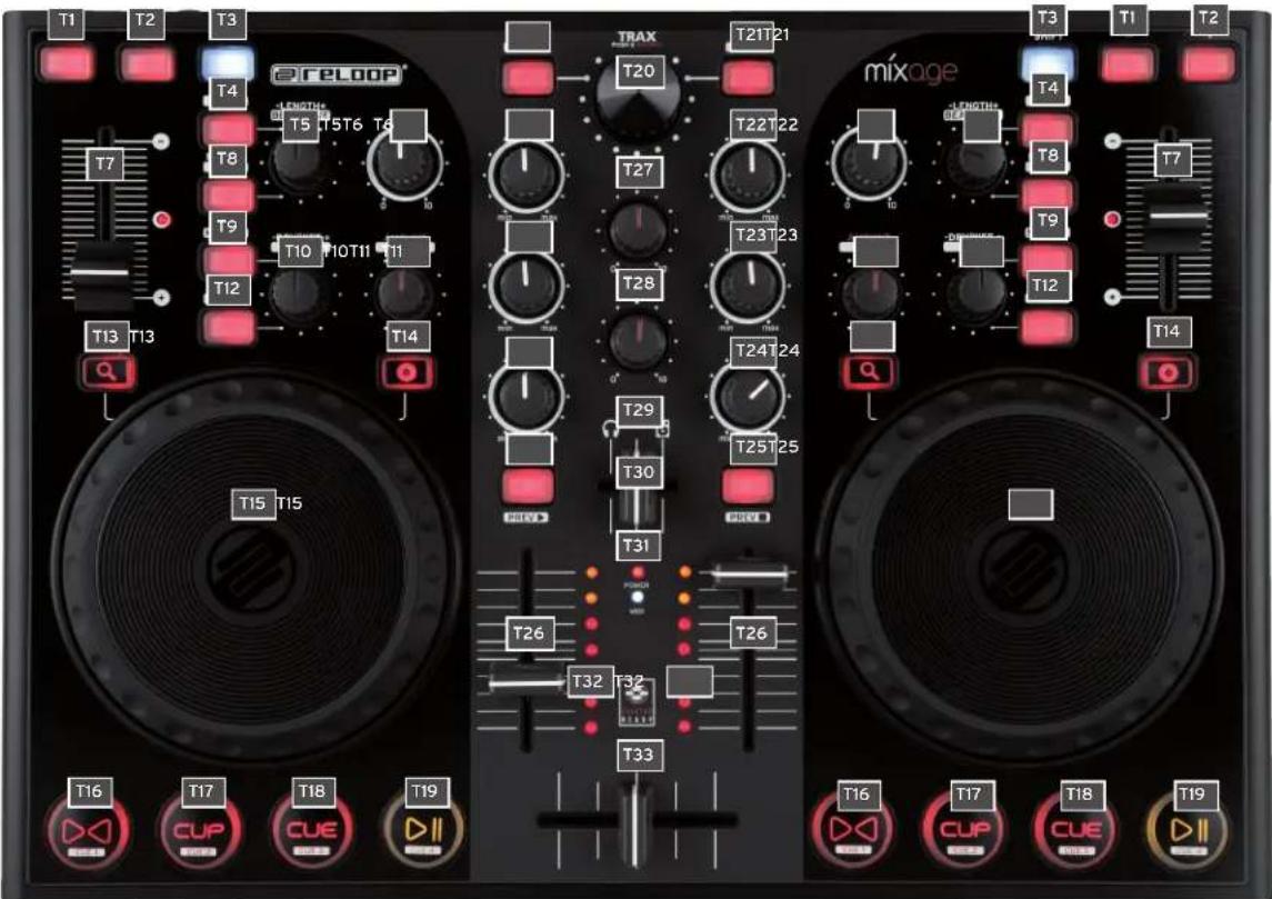


1.1. CONTROL ELEMENTS & CONNECTIONS
SURFACE
T1. Pitch Bend - Button
T2. Pitch Bend + Button
T3.ShiftButton
T4. Autoloop Button (Shift: Loop In)
T5. Loop Length - / + (Shift: Beat Move > only Traktor Pro)
T6. Gain Dial
T7. Pitchfader incl. Status LED Indicator (illuminated at 0%)
T8. Reloop Button (Shift: Loop Out)
T9. FX Select Button (Shift: Master Deck Assignment)
T10. FX Dry/Wet + Dial (Shift: Pan Balance Dial)
T11. Amount (FX Parameter 1) Dial (Shift: Filter)
T12. FX On Button (Shift: Keylock Button)
T13. Search Mode Button
T14. Scratch Mode Button
T15. Jog Wheel
T16. × Sync Button (Shift: Cue 1 > only Traktor Pro)
T17. Cup Button (Shift: Cue 2 > only Traktor Pro)
T18. Cue Button (Shift: Cue 3 > only Traktor Pro)
T19. Play/Pause Button (Shift: Cue 4 > only Traktor Pro)
T20. Trax Encoder (Shift: Folder Navigation)
T21. Track Load Button (Shift: Open Folder [L], Close Folder [R])
T22. High (Highs EQ) Dial
T23. Mid (Mids EQ) Dial
T24. Low (Bass EQ) Dial
T25. Cue Button (Shift: Track Pre-Listen Play [L] / Stop [R])
T26. Linefader
T27. Master Volume Dial (analog, not software)
T28. Phones Volume Dial (analog, not software)
T29. Cue Mix Fader
T30. Power Status LED (illuminated when controller is turned on, if voltage is provided)
T31. MIDI Status LED (illuminated when transferring MIDI signal)
T32. Master Level LED Indicator
T33.Crossfader
REAR PANEL
B39. USB Port
B40. MIDI Channel 1/2 Switch
B41. Shift Lock On/Off Switch
B42. RCA Output (Audio Outputs)
FRONT PANEL
F34. 6.3 mm Jack Microphone Connection
F35. Microphone Level Dial
F36. SW/Thru/Off Switch (switches microphone routing)
F37. 6.3 mm Jack Headphones Connection
RIGHT SIDE
S38. Kensington Lock
The device is automatically supplied with electrical current as soon as a USB connection to a computer has been set up. Connect the included USB cable to the corresponding port -B39- on the device's rear panel and a free USB port of your computer.
3.COMPUTER CONFIGURATION
Before you can use your new device a few basic computer adjustments have to be carried out.

ATTENTION!
Please make sure that your Reloop Mixage is turned off (disconnect the USB cable -B39-). You will be asked during the installation to turn on the device respectively connect the USB cable. Please especially observe the following explanations.
3.1. ASIO DRIVER INSTALLATION
In order for the audio signals to be sent quickly to the device, so called ASIO drivers are necessary. Depending on the operating system in use, different steps are necessary to carry out the installation.
3.1.1. WINDOWS
Insert the included installation CD into your CD drive. In the file „Audio Drivers“ select the driver setup and start the installation with a double click.
TIPI!
Reloop regularly provides updated drivers online. For more information please read the chapter „Updates & Support".

NOTE!
Please make sure to start the driver installation with admin rights. Otherwise the installation will fail with an error message.
If you use Windows Vista or Windows 7 please carry out the installation setup via a click of the right mouse button followed by the selection „Run as admin".
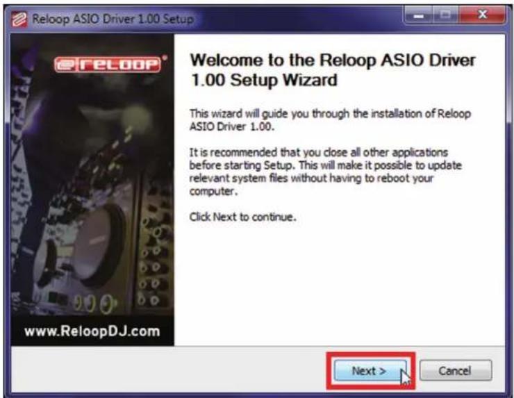
- At first a welcome window will appear. Simply press „Next".
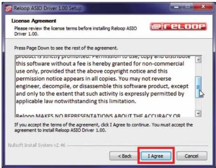
- Carefully read the license agreement. Click on the "I Agree" button if you agree and you wish to install the driver.
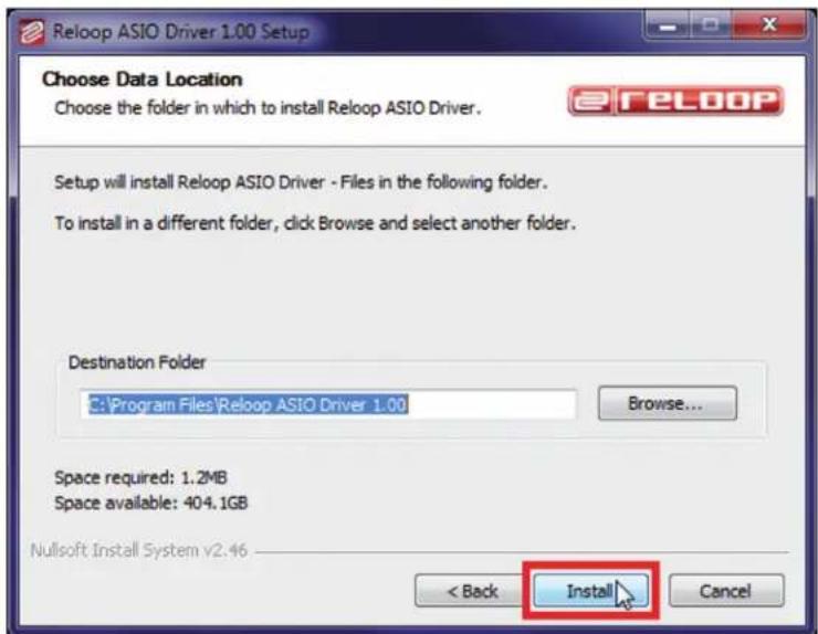
- In the following dialogue simply click „Install". The proposed path does not need to be changed.
- After the installation click "Finish".
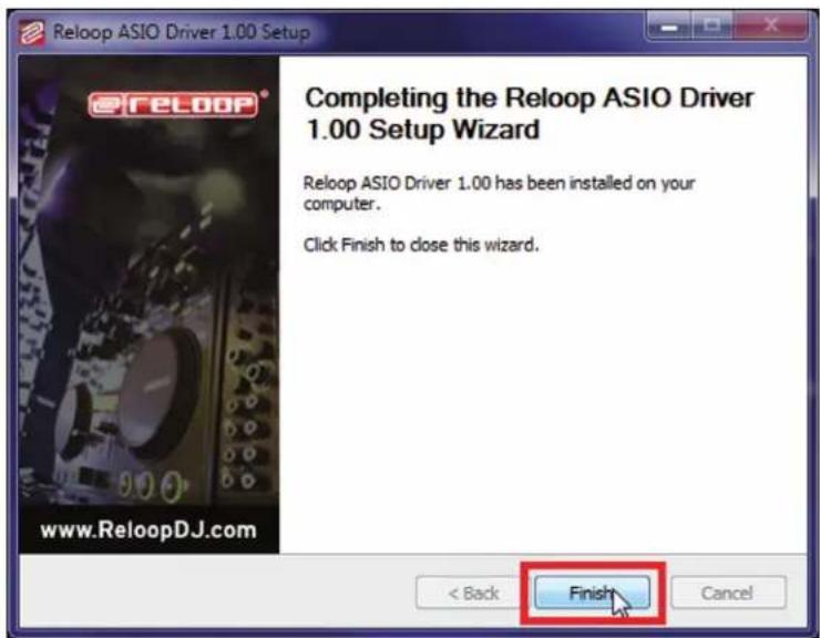
Please restart your PC.
- Now it is time to check the connection between Reloop Mixage and the PC software. To do so connect the included USB cord to the USB port -B39- of Reloop Mixage and a free USB port of your computer. That followed, please wait at least 30 seconds until the computer has fully recognised the device.
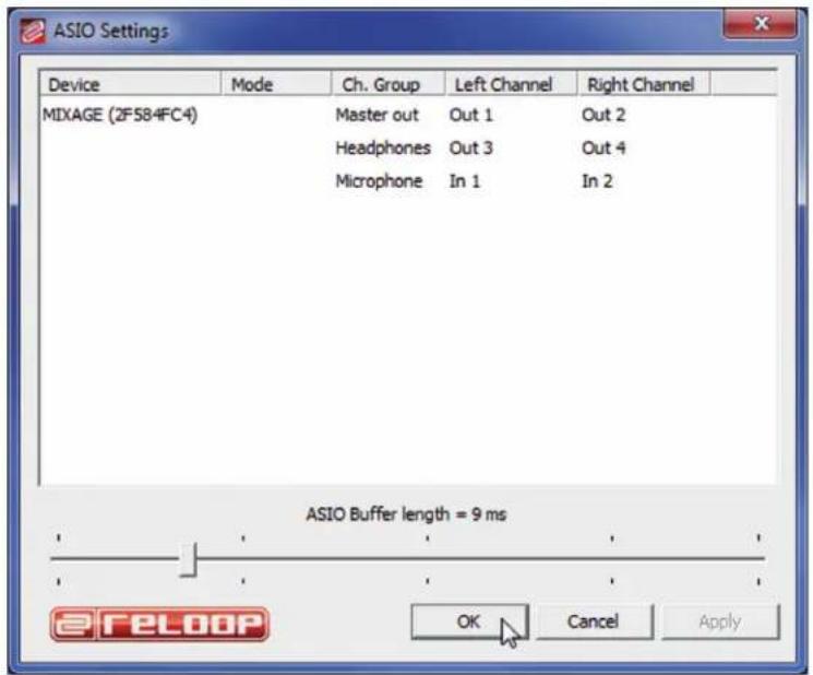
In order to carry out the connection test switch to the program directory „Reloop ASIO Driver [...]” and start the subordinate program „ASIO Settings". After a brief moment „Mixage" should be listed as item.
3.1.2. MAC
If you use the operating system Mac OS you will not need any driver in order to install Reloop Mixage. The integrated audio interface is supported natively by Core Audio®.
Simply connect the included USB cord to the USB port -B39- of Reloop Mixage and a free USB port of your computer.
Upgrade to Traktor PRO (4 deck support):
Via the included Traktor LE version you are able to purchase the extensive Traktor PRO version at a bargain price. Current price conditions can be found under www.nativeinstruments.de
3.2.1. INSTALLATION

Besides the ASIO drivers, on the included installation CD you can also find a directory named „Traktor". Open this directory and select the setup file that best suits your system. Follow the instructions from the installation window.
NOTE!
Details regarding the system requirements can be found in the appendix under item „System Requirements Traktor LE".
3.2.2. CONFIGURATION
If Traktor LE is used for the first time the „Setup Wizard“ should start. If this is not the case please click on „Help“ and select the menu item „Start Setup Wizard“. In the setup wizard select the following items:
- Answer the first question „Are you using a USB/FireWire Controller?“ with „Yes“. Then click on „Next“.
- In the field, "Choose your manufacturer" select the item "Reloop". The following menu item "Choose your model" has to be answered with "Mixage". Again confirm this selection with "Yes".
- The following question regarding connected hardware by manufacturer „Native Instruments" has to be answered with „No".
Your Reloop Mixage should now be configured accordingly for Traktor LE.
3.3. AUDIO SETUP & MAPPING IMPORT
In order to be able to use Traktor with your setup combined with Mixage, please observe the following items in detail.
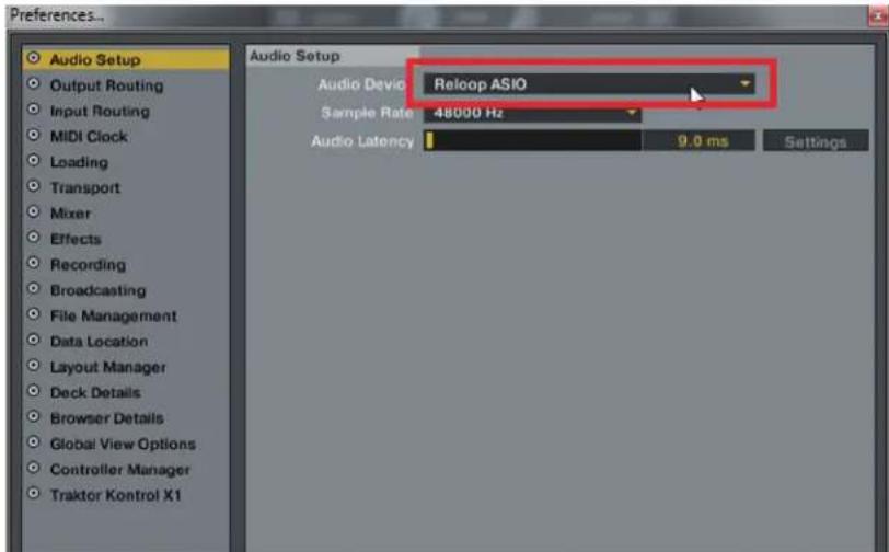
3.3.1.AUDIO SETUP
- In Traktor open the setup dialogue by clicking the small cog wheel on the upper right corner.
- Open the category „Audio Setup" and in the filed „Audio Device" select the item „Reloop ASIO (ASIO)".
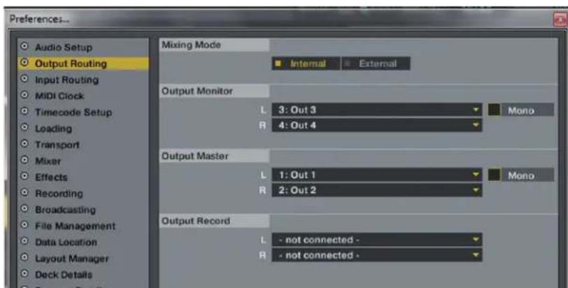
- Open the category „Output Routing" and in the field „Mixing Mode" select the button „Internal". For channel assignment please see the following example.
3.3.2. MAPPING IMPORT [ONLY TRAKTOR PRO]
![Reloop Mixage Interface Edition MK2 - MAPPING IMPORT [ONLY TRAKTOR PRO] - 1](/content/2026/02/379574/images/81015f6cff2201ca6e132ee7958319288aa8580ff951aaa3f9cce417d277ce2f.jpg)
In order for Traktor to be able to assign the MIDI commands that Mixage sends to the correct functions, a special mapping is necessary.
A suitable mapping can be found on the installation CD in the folder „Mappings/Traktor Pro".
NOTE!
You can find updated and extended mappings online. Go to http://www.reloopdj.com/forum and open the category „Mapping files" in the field „Downloads for all Reloop products".
Please proceed as follows in order to import the mapping:
- In Traktor open the adjustment dialogue by clicking the small cog wheel in the upper right corner.
- Open the category „Controller Manager".
- In order to avoid problems it is recommended to delete all existing entries apart from the keyboard mappings from the controller manager: To do so select one entry after the other in the field „Device" and press „EDIT...” followed by „Delete".
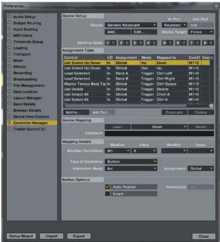
- Now select the button „Add...” followed by „Import“.
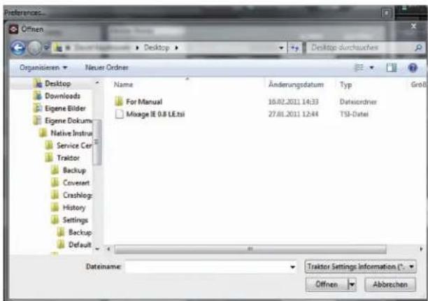
In the selection screen open the mapping file that is found on the CD or that was downloaded from the Reloop support site.
Troubleshooting
Should a problem arise and Mixage's LEDs are not lit correctly, this is probably caused in most cases by installed MIDI software (e.g. MidiYoke, Maple Virtual MIDI Cable, etc.).
In order to solve the problem proceed as follows:
- In Traktor open the adjustment dialogue by clicking the small cog wheel in the upper right corner.
- Open the category „Controller Manager".
- For the following device entries the following port assignments have to be configured:
| Device In-Port Out-Port | ||
| Mixage V* Reloop Mixage Reloop | Mixage |
4. OPERATION
After connecting and configuring Reloop Mixage correctly for the DJ software, Traktor can now be used.

NOTE!
In the following the whole Traktor function assignment will be described. Some features are only available in Traktor Pro and therefore they have been marked grey in the following chart.
| Element Function | Function with activated Shift -T3- | |
| T1 Pitch Bend | - Button Allows the temporary deceleration (counter-clockwise) of a track. | |
| T2 | Pitch Bend + Button Allows the temporary acceleration (clockwise) of a track. | |
| T3 Shift Button | By pressing this button all the device's control elements receive a different function. The current assignment can be viewed on the right side of this chart. | |
| T4 Autoloop | Button Sets an automatic loop with the set loop length (-T15-), without the necessity of setting the loop ending point manually. | Loop In / Set Cue Button Manually sets the starting point of a loop. Simultaneously a cue point will be defined. |
| T5 Loop Length | -/+ Dial By turning the encoder the set loop's length can be varied. By pressing the encoder the loop active function can be activated and deactivated respectively. | Beat Move Dial Carries out a beatjump in or opposed to playback direction |
| T6 Gain Dia | Preamplification of a track/deck. | |
| T7 Pitchfader | er incl. Status LED Herewith it is possible to exactly adjust the pitchfader of the current deck. In 0% position the LED is illuminated. | |
| T8 Reloop Button | Jumps to the last stored loop and reactivates it. | Loop Out Button Manually sets the ending point of a loop. Now the deck is in loop mode; the selected passage will be repeated continuously. Renewed pressing stops the loop mode. |
| T9 FX Select | Button By pressing the button it is possible to scroll through the effects. | Master Deck Assignment The current deck becomes the master deck. |
| T10 FX Dry/ | Wet+ Dial Herewith it is possible to quickly change the effect's intensity. | Pan Dial Herewith it is possible to adjust the volume division between the left and right channel. The zero position corresponds to an equal level on both channels. |
| T11 Amount | (FX Parameter 1) Dial In Effect Mode the parameters can be adjusted herewith. NOTE! In Traktor LE only the 1st parameter works in Chained Effect Mode. | Filter Regulates the filter effect for the activated deck. In zero position the filter will automatically be deactivated. |
| T12 FX On Taste | taste Activates the FX section corresponding to the deck. | Keylock Button (De-)activates Keylock. |
| T13 Search | Mode Button Allows quick scrolling through a loaded track. | |
| T14 Scratch | Mode Button Activates the jog wheel's scratch function and the pitch bend function at the edge of the jog wheel. | |
| T15 Jog Wheel | Herewith various functions can be controlled. | |
| T16 Sync Button | The current deck's pitch will be synchronized to the master deck. | Cue 1 Button Sets and triggers the 1st cue point. |
| T17 Cup Button | As long as this button is being pressed the deck jumps to the last set cue point and stops. When releasing the button playback will start. | Cue 2 Button Sets and triggers the 2nd cue point. |
| T18 Cue Button | Herewith the cue point will be triggered and played for as long as the button is being held. | Cue 3 Button Sets and triggers the 3rd cue point. |
| T19 Play/Pause | Button Starts and pauses the track's playback respec-tively. | Cue 4 Button Sets and triggers the 4th cue point. |
| T20 TRAX Encoder (Tracklist Navigation) | - By turning the encoder it is possible to scroll through the track list. - By pressing the encoder browser view will be maximized. | TRAX Encoder (Folder Navigation) - By turning the encoder it is possible to navigate through the folders. |
| T21 Track Load | Load Button Assigns the selected track to the deck. | Load Button Open folder [L], close folder [R] |
| T22 High Dial | Regulates the high EQ. | |
| T23 Mid Dial | Regulates the mid EQ. | |
| T24 Low Dial | Regulates the bass EQ. | |
| T25 Cue Buttons | By pressing one of the Cue Buttons the mo-nitoring function for the selected deck will be activated. | Cue Button Track Pre-Listen Play [L] / Stop [R] |
| T26 Linefader Regulates the respective channel's volume. | |
| T27 Master | Volume Dial (analog, not software) The dial adjusts the master output's volume. |
| T28 Phones | Dial (analog, not software) The dial adjusts the headphones' volume. |
| T29 Cue Mix | Fader With the Cue Mix Fader it is possible to simulate a pre-mix via the headphones. In the right position the master signal is audible, in the left position the cue signal is audible. |
| T30 Power | Status LED Illuminated when the controller is turned on, if voltage is provided. |
| T31 MIDI Status | Status LED Illuminated when MIDI signals are sent. |
| T32 Master | Level LED Indicator Optically displays the master output level. |
| T33 Crossfader Crossfader between ch.1 and ch.2 |
5. DEVICE SETTINGS AND TESTS
There are a few settings and tests which can be carried out directly with Mixage without the need for a computer. In the following a few points will be explained more thoroughly.
5.1. MIDI CHANNEL ASSIGNMENT

NOTE!
By default Mixage is configured for MIDI channels 1 or 2. The MIDI channel can be selected via the switch on the rear side -B40-.
It is possible to connect a further Mixage controller, i.e. for DJ teams. For this purpose it is important that one Mixage is on MIDI channel 1 and the second Mixage is on MIDI channel 2 (see switch -B40-).
Reloop's official mappings are laid-out according to the standard configuration. Therefore changes are usually unnecessary.

NOTE!
Updated and advanced mappings can also be found online. Go to http://www.reloopdj.com/forum and open the category „Mapping Files" under „Downloads for all Reloop products".
5.2. LED FUNCTIONAL TEST
Herewith it is possible to check whether all of Mixage's LEDs work properly.
To carry out the functional test proceed as follows:
- Make sure that Mixage is turned off (USB cable has to be disconnected -B39-).
- Press and hold the left Sync Button -T16- and turn on Mixage by connecting the USB cable -B39-.
- Now release the Sync Button -T16-.
- Now all LEDs should be illuminated.
- In order to finish the test, simply turn off the device by disconnecting the USB cable -B39-.
6. UPDATES & SUPPORT
For Reloop Mixage it is possible to update its firmware. This way changes can be applied and new features added subsequently. Instructions on how to proceed can be found online under the below mentioned address. Especially updated drivers for the integrated audio interface are offered which can be downloaded.
6.1. FIRMWARE CHECK
- Turn off the device by disconnecting the USB cable -B39-.
- Press and hold the right Shift Button -T3-.
- Re-connect the device via the USB cable -B39-.
- The current firmware version is displayed via a binary system with help from the transport section (Cue Buttons). The following values display the firmware version: Cue4>1, Cue3>2, Cue2>4, Cue1>8; example: firmware version 5 = Cue4 + Cue2
- In order to leave this mode disconnect the USB cable -B39-. A maximum of 15 versions can be displayed.
6.2 FIRMWARE UPDATE
- Make sure that Mixage is turned off (disconnect the USB cable).
- Press and hold the right Cup Button -T17- and the right Cue Button -T18- and simultaneously turn on Mixage by connecting the USB cable -B39-.
- Now release both buttons.
- The Power Status LED -T31- will start to flash. Mixage is now in update mode.
- Now start the firmware update tool from the installation CD and open the firmware file that suits your device.
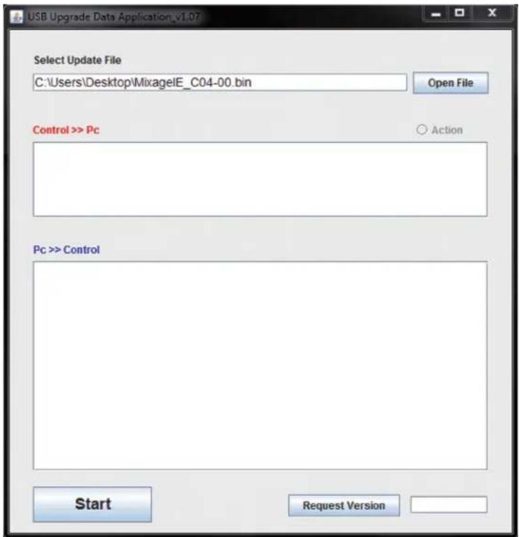
- Carry out the firmware update by clicking the start button.
7. The new firmware will now be assigned to the device.
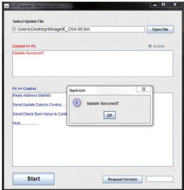
- If the update is successful, the Power Status LEDs -T30- and MIDI Status LEDs -T31- will flash simultaneously. If the update failed the Status LEDs will start flashing alternatingly.
- After having carried out the update successfully close the frimware update tool and disconnect the USB cable -B39-.
- After a successful update you can re-check the firmware. Please refer to item 6.1 „Firmware Check" under 6. „Updates & Support".
In order to be able to utilize Reloop Mixage in the future, updated mappings are offered for Traktor (Pro) follow-up versions and other softwares. Additionally it is possible to purchase special mappings for differing setups, that derive from the user community. Therefore regularly check the following website:
www.reloopdj.com/forum
Besides numerous downloads you can also find a support forum.
7. APPENDIX
7.1. SYSTEM REQUIREMENTS NATIVE INSTRUMENTS TRAKTOR LE
Supported Audio Formats:
MP3, WAV, AIFF, Audio-CD, FLAC, Ogg Vorbis, non-DRM WMA*, non-DRM AAC (WMA playback only for Windows)
System Requirements:
WIN:
Windows® XP (latest Service Pack, 32 bit) or Windows Vista® (latest Service Pack 32/64 bit) or Windows® 7 (latest Service Pack, 32/64 bit), Intel® Pentium 4® 2.4 GHz or Intel® Core Duo™ or AMD Athlon™ 64, 2 GB RAM
Mac:
Mac OS® X 10.5 (latest update) or higher, Intel® Core™ Duo, 2 GB RAM
Driver:
ASIO®, Core Audio, DirectSound®, WASAPI™
7.2. MIDI ASSIGNMENT CHART
| SW name | Type | MIDI | MIDI 2 (Shift) | Remarks |
| TRAX | SW/ENC 1F/1F | 5E/5E | ||
| CD1 LENGTH | SW/ENC 20/20 | 5F/5F | ||
| CD1 DRY/WET | SW/ENC 21/21 | 60/60 | ||
| CD1 JOG | SW/ENC 24/24 63/63 | |||
| CD1 JOG CW | SW/ENC 24/24 63/63 SC RATCH LED = ON & No Touch Inner Wheel | |||
| CD1 JOG CCW | SW/ENC 24/24 63/63 SC RATCH LED = ON & No Touch Inner Wheel | |||
| CD2 LENGTH | SW/ENC 22/22 61/61 | |||
| CD2 DRY/WET SW | SW/ENC 23/23 62/62 | |||
| CD2 JOG SW/ENC | 25/25 64/64 | |||
| CD2 JOG CW SW | ENC 25/25 64/64 SC RATCH LED = ON & No Touch Inner Wheel | |||
| CD2 JOG CCW SW | W/ENC 25/25 64/64 SC RATCH LED = ON & No Touch Inner Wheel | |||
| CD1 SHIFT SW 2A | ||||
| CD2 SHIFT SW 2B | ||||
| CD1 PITCH PitchBend MIDI CH = 1:CH1 MIDI CH = 2:CH5 MIDI CH= 1:CH3 MIDI CH= 2:CH7 | ||||
| CD2 PITCH | PitchBend MIDI CH = 1:CH2 MIDI CH = 2:CH6 MIDI CH= 1:CH4 MIDI CH= 2:CH8 | |||
| CD1 GAIN | VR | 33 | 72 | |
| CD1 FILTER | VR/CENTER 34/34 | 73/73 | ||
| CD1 HIGH | VR | 35 | 74 | |
| CD1 MID | VR | 36 | 75 | |
| CD1 LOW | VR | 37 | 76 | |
| CD1 CH FADER | VR | 38 | 77 | |
| CD2 GAIN | VR | 39 | 78 | |
| CD2 FILTER | VR/CENTER 3A/3A | 79/79 | ||
| CD2 HIGH | VR | 3B | 7A | |
| CD2 MID | VR | 3C | 7B | |
| CD2 LOW | VR | 3D | 7C | |
| CD2 CH FADER | VR | 3E | 7D | |
| CUEMIX | VR | 32 | -- | CH1 Only |
| CROSSFADER | VR | 31 | -- | CH1 Only |
| CD1 - | SW/LED | 01/01 | 40/01 | |
| CD1 + | SW/LED | 02/02 41/02 | ||
| CD1 Search | SW/LED | 03/03 42/03 | ||
| CD1 Scratch | SW/LED | 04/04 | 43/04 | |
| CD1 LOOP | SW/LED | 05/05 | 44/05 | |
| CD1 RELOOP | SW/LED | 06/06 | 45/06 | |
| CD1 FX SEL | SW/LED | 07/07 | 46/07 | |
| CD1 FX ON | SW/LED | 08/08 | 47/08 | |
| CD1 CUE1 | SW/LED | 09/09 48/09 | ||
| CD1 CUE2 SW/LED | OA/OA | 49/OA | ||
| CD1 CUE3 | SW/LED | OB/OB | 4A/OB | |
| CD1 CUE4 | SW/LED | OC/OC | 4B/OC | |
| CD1 LOAD | SW/LED 0D/0D | 4C/0D | ||
| CD1 HP | SW/LED OE/OE | 4D/OE | ||
| CD2 - | SW/LED OF/OF | 4E/OF | ||
| CD2 + SW/LED 10/10 | 4F/10 | |||
| CD2 Search | SW/LED 11/11 | 50/11 | ||
| CD2 Scratch | SW/LED 12/12 | 51/12 | ||
| CD2 LOOP SW/LED 13/13 52/13 | ||||
| CD2 RELOOP | SW/LED 14/14 | 53/14 | ||
| CD2 FX SEL | SW/LED 15/15 | 54/15 | ||
| CD2 FX ON | SW/LED 16/16 | 55/16 | ||
| CD2 CUE1 | SW/LED 17/17 | 56/17 | ||
| CD2 CUE2 SW/LED 18/18 57/18 | ||||
| CD2 CUE3 SW/LED 19/19 58/19 | ||||
| CD2 CUE4 SW/LED 1A/1A 59/1A | ||||
| CD2 LOAD SW/LED 1B/1B 5A/1B | ||||
| CD2 HP SW/LED1C/1C 5B/1C | ||||
| CH1 Level Meter | LEVEL 1D 0~7 | |||
| CH2 Level Meter | LEVEL 1E 0~7 | |||
CC-ABSOLUTE (VR)
Control Change messages are sent with status OxBn, where n is the channel, for the specified CC controller. Thus the controller MIDl ID is indicated with the channel along with the CC number. The value from 0x00 to 0x7F, directly related to the location of the controller.
CC-RELATIVE (ENC)
Control Change messages are status 0xBn , where n is the channel, for the specified CC controller. Thus the controller MIDI ID is indicated with the channel along with the CC number. The value from 0x40 to indicate the change in the controller. This is an offset to 0x40 "one's complement" notation. A message with data 0x43 indicates a positive change of 3.
A messages with data 0x31 indicates a negative change of 15.
SWITCH ON/OFF (SW,CENTER, CW, CCW)
These messages are used for switches.
Control Change messages are sent with status 0x9n , SWITCH On and Off value are 0x7F and 0x00 where n is the channel.
LED ON/OFF (LED)
These messages are used for LED.
Control Change messages are sent with status Ox9n, LED On and Off value are Ox7F and Ox00, where n is the channel.
PITCHBEND
Pitchbend messages are status OxEn, where n is the channel, for the specified controller.
Thus the controller ID is indicated only by the channel.
For accurate changes, the 14 bit data in a pitch bend message is reserved for absolute controllers which require more than 7 bits of data.
LEVELLED (LEVEL)
These messages are used for LEVEL.
Control Change messages are sent with status 0x9n , LED Off value is 0x00 and On value is related to LED amount, 0x01 with one LED, 0x02 with two LED..., where n is the channel.
7.3. TROUBLESHOOTING
If any problem should arise while using Reloop Mixage the following chart is the first drop-in center:
| Symptoms Possible Causes Corrective Measures | ||
| The device does not receive any power. | USB cable is not correctly connected. | Check whether the USB cord is correctly connected to a free USB port of your computer and Mixage's USB port -B39-. |
| The controller's LEDs are only weakly lit and the device does not react. | The power supply is not sufficient. | The USB connection does not generate enough electrical current. Disconnect all other USB devices from your computer. |
| Not all outputs of the integ-rated audio interface can be selected in the DJ software. | The ASIO driver is not installed correctly. | Please install the ASIO driver again. Also please read the paragraph „ASIO Driver Installation" in the chapter „Computer Configuration". |
| The audio interface's sound is distorted. | The ASIO driver is not used. The performance settings of your computer do not correspond to the computer's capacity. | Please make sure that the ASIO driver is installed and is also being used. Please refer to the paragraph „ASIO Driver Installation" in the chapter „Computer Configuration".It is also possible that in the ASIO driver's settings the available computer capacity has to be re-configured. Open the settings in Traktor, select the category „Audio Setup" and click on the „settings" button next to the sound card selection window. Then select „System Performance" -> „Normal". If the problems persist you can also select „Relaxed" in the same menu. |
| The DJ software does not show any reaction to the usage of any of the controller's control elements. | Traktor LE is not configured correctly. Traktor Pro is not installed correctly. MIDI channel is not selected correctly. | If you use the included Traktor LE version, start the Setup Wizard again. Refer to the paragraph „Traktor LE Setup" in the chapter „Computer Configuration". When using Traktor Pro the mapping has to be loaded again. To do so follow the instructions in the paragraph „Traktor Pro Configuration" in the chapter „Computer Configuration". Check the MIDI Channel Switch -B40- and put it in the right position (ch. 1 or ch. 2). Please refer to the paragraph „MIDI Channel Assignment", chapter „Device Settings & Tests". |
| A problem occurs that is not listed in this chart. | Various causes. Visit www.reloop | dj.com/forum, in order to get support regarding your Reloop products. |
7.4 TECHNICAL SPECIFICATIONS
The following specifications are not verified by Global Distribution GmbH in terms of plausibility and accuracy:
Dimensions: 370 x 61 x 266 mm
Weight: 2.4 kg
Input/Output Impedance & Sensitivity: EQ Flat, Maximum Gain, Load = 100 kohm
Frequency Range (EQ Flat, Maximum Gain, Load = 100 kohm):
Line: .17 Hz - 16 kHz +/-0.5 dB
Mic. 20 hz - 20 kHz +/-1,5 dB
THD + N (EQ Flat, Maximum Gain, Mic = Off, Load = 100 kohm, w/20 kHz LPF):
Line: 0.01% 1 kHz/0 dB
S/N Ratio (Maximum Gain, EQ Flat, w/20 kHz LPF, A-Weighted, Master = 0 dBV Outout):
Line: 95 dB
Mic: 68 dB
Channel Separation (Maximum Gain, EQ Flat, 1 kHz = 0 dB, Mic Switching = Off):
L/R: 85 dB

Reloop Distribution
Global Distribution GmbH, Schuckertstrasse 28,
48153 Munster / Germany
Fax: +49.251.6099368
Subject to technical alterations!
Illustrations similar to original product!
Misprints excepted!
MODE D'EMPLOI

ATTENTION!
B39.Port USB
B40. Touche MIDI Channel 1/2
B41. Touche Shift Lock On/Off
B42. Cinch Output (sorties audio)
FACE AVANT DE L'APPAREIL
ASIO®, Core Audio, DirectSound®, WASAPI™
7.2. TABLE D'AFFECTATION MIDI
| SW name | Type | MIDI | MIDI 2 (Shift) | Remarks |
| TRAX | SW/ENC 1F/1F | 5E/5E | ||
| CD1 LENGTH | SW/ENC 20/20 | 5F/5F | ||
| CD1 DRY/WET | SW/ENC 21/21 | 60/60 | ||
| CD1 JOG | SW/ENC 24/24 63/63 | |||
| CD1 JOG CW | SW/ENC 24/24 63/63 SC RATCH LED = | ON & No Touch Inner Wheel | ||
| CD1 JOG CCW | SW/ENC 24/24 63/63 SC RATCH LED = | ON & No Touch Inner Wheel | ||
| CD2 LENGTH | SW/ENC 22/22 61/61 | |||
| CD2 DRY/WET S | W/ENC 23/23 62/62 | |||
| CD2 JOG SW/ENC | 25/25 64/64 | |||
| CD2 JOG CW SW | ENC 25/25 64/64 SC RATCH LED = | ON & No Touch Inner Wheel | ||
| CD2 JOG CCW SW | W/ENC 25/25 64/64 SC RATCH LED = | ON & No Touch Inner Wheel | ||
| CD1 SHIFT SW 2A | ||||
| CD2 SHIFT SW 2B | ||||
| CD1 PITCH | PitchBend | MIDI CH = 1:CH1MIDI CH = 2:CH5 | MIDI CH=1:CH3MIDI CH=2:CH7 | |
| CD2 PITCH | PitchBend | MIDI CH = 1:CH2MIDI CH = 2:CH6 | MIDI CH=1:CH4MIDI CH=2:CH8 | |
| CD1 GAIN | VR | 33 | 72 | |
| CD1 FILTER | VR/CENTER | 34/34 | 73/73 | |
| CD1 HIGH | VR | 35 | 74 | |
| CD1 MID | VR | 36 | 75 | |
| CD1 LOW | VR | 37 | 76 | |
| CD1 CH FADER | VR | 38 | 77 | |
| CD2 GAIN | VR | 39 | 78 | |
| CD2 FILTER | VR/CENTER | 3A/3A | 79/79 | |
| CD2 HIGH | VR | 3B | 7A | |
| CD2 MID | VR | 3C | 7B | |
| CD2 LOW | VR | 3D | 7C | |
| CD2 CH FADER | VR | 3E | 7D | |
| CUEMIX | VR | 32 | -- | CH1 Only |
| CROSSFADER | VR | 31 | -- | CH1 Only |
| CD1 - | SW/LED | 01/01 | 40/01 | |
| CD1 + | SW/LED | 02/02 | 41/02 | |
| CD1 Search | SW/LED | 03/03 42/03 | ||
| CD1 Scratch | SW/LED | 04/04 | 43/04 | |
| CD1 LOOP | SW/LED | 05/05 | 44/05 | |
| CD1 RELOOP | SW/LED | 06/06 | 45/06 | |
| CD1 FX SEL | SW/LED | 07/07 | 46/07 | |
| CD1 FX ON | SW/LED | 08/08 | 47/08 | |
| CD1 CUE1 | SW/LED | 09/09 48/09 | ||
| CD1 CUE2 | SW/LED | 0A/0A | 49/0A | |
| CD1 CUE3 | SW/LED | 0B/0B | 4A/0B | |
| CD1 CUE4 | SW/LED | OC/OC | 4B/OC | |
| CD1 LOAD SW/LED | ED OD/OD | 4C/OD | ||
| CD1 HP | SW/LED OE/OE | 4D/OE | ||
| CD2 - SW/LED 0F/OF | 4E/OF | |||
| CD2 + SW/LED 10/10 4F/10 | ||||
| CD2 Search | SW/LED 11/11 | 50/11 | ||
| CD2 Scratch | SW/LED 12/12 51/12 | |||
| CD2 LOOP SW/LED 13/13 52/13 | ||||
| CD2 RELOOP | SW/LED 14/14 53/14 | |||
| CD2 FX SEL | SW/LED 15/15 54/15 | |||
| CD2 FX ON | SW/LED 16/16 55/16 | |||
| CD2 CUE1 | SW/LED 17/17 | 56/17 | ||
| CD2 CUE2 SW/LED 18/18 57/18 | ||||
| CD2 CUE3 SW/LED 19/19 58/19 | ||||
| CD2 CUE4 SW/LED 1A/1A 59/1A | ||||
| CD2 LOAD SW/LED 1B/1B 5A/1B | ||||
| CD2 HP SW/LED 1C/1C 5B/1C | ||||
| CH1 Level Meter | LEVEL 1D 0~7 | |||
| CH2 Level Meter | LEVEL 1E 0~7 | |||
CC-ABSOLUTE (VR)
Control Change messages are sent with status OxBn, where n is the channel, for the specified CC controller. Thus the controller MIDI ID is indicated with the channel along with the CC number. The value from 0x00 to 0x7F, directly related to the location of the controller.
CC-RELATIVE (ENC)
Control Change messages are status 0xBn where n is the channel, for the specified CC controller. Thus the controller MIDI ID is indicated with the channel along with the CC number. The value from 0x40 to indicate the change in the controller. This is an offset to 0x40 "one's complement" notation. A message with data 0x43 indicates a positive change of 3.
A messages with data 0x31 indicates a negative change of 15.
SWITCH ON/OFF (SW,CENTER,CW,CCW)
These messages are used for switches.
Control Change messages are sent with status 0x9n , SWITCH On and Off value are 0x7F and 0x00 where n is the channel.
LED ON/OFF (LED)
These messages are used for LED.
Control Change messages are sent with status 0x9n LED On and Off value are 0x7F and 0x00 where n is the channel.
PITCHBEND
Pitchbend messages are status OxEn, where n is the channel, for the specified controller.
Thus the controller ID is indicated only by the channel.
For accurate changes, the 14 bit data in a pitch bend message is reserved for absolute controllers which require more than 7 bits of data.
LEVELLED (LEVEL)
These messages are used for LEVEL.
Control Change messages are sent with status 0x9n, LED Off value is 0x00 and On value is related to LED amount, 0x01 with one LED, 0x02 with two LED..., where n is the channel.
7.3. CONSEILS DE DÉPANNAGE
THD + N (EQ Flat, Maximum Gain, Mic = Off, Load = 100 kohm, w/20 kHz LPF):
Line: 0.01% 1 kHz / 0 dB
Rapport signal/bruit (Maximum Gain, EQ Flat, w/20 kHz LPF, A-Weighted, Master = 0 dBV Output):
Line: 95 dB
Mic: 68 dB
Déparation des caneaux (Maximum Gain, EQ Flat, 1 kHz = 0 dB, Mic Switching = Off):
L/R: 85 dB

Reloop Distribution
Global Distribution GmbH, Schuckertstrasse 28,
48153 Munster / Germany
Fax: +49.251.6099368