
DL431 - Mixer Midas - Free user manual and instructions
Find the device manual for free DL431 Midas in PDF.

| Product Type | Micro Splitter for XL8 live system |
| Brand and Model | Midas DL431 |
| Category | Mixing Console / Stage Equipment |
| Dimensions (rack) | 6U, 19 inches |
| Power Supply | Redundant dual power supply with IEC inputs and on/off switches |
| Number of Microphone/Line Inputs | 24 inputs with female XLR connectors |
| Preamps per Channel | Three completely independent preamps (two variable gain, one fixed gain for broadcast) |
| Analog Splits | Two balanced analog outputs (splits) per input + transformer-isolated C outputs |
| Digital Connectivity | AES50 audio via EtherCon® connectors (A and B, X and Y) for audio and control |
| Control and Monitoring | Control panel with LCD screen, mic preamp selection (A/B), gain adjustment, 30 Hz filter, 48V phantom power |
| Built-in Headphone Amplifier | Yes, with jack socket and level control on front panel |
| Main Functions | Microphone signal distribution to FOH and MON consoles, AES50 outputs, Ethernet and USB tunnels, dual power redundancy |
| Material and Construction | Robust metal chassis, rack mount with front and rear supports |
| Maintenance and Cleaning | Clean with a dry, lint-free cloth. LCD screen with mild cleaner. Annual cleaning of internal fans by qualified technician. |
| Safety | Mandatory grounding, do not open the cover, do not expose to moisture, use in tropical or moderate climate (max 45°C) |
| Spare Parts and Repairability | Repair reserved for qualified personnel. Contact Midas support or an authorized service center. Replace fuses with identical models. |
| General Information | Designed and manufactured in the UK. Integral part of the XL8 Live Performance system. Limited warranty available at community.musictribe.com |
Frequently Asked Questions - DL431 Midas
User questions about DL431 Midas
0 question about this device. Answer the ones you know or ask your own.
Ask a new question about this device
Download the instructions for your Mixer in PDF format for free! Find your manual DL431 - Midas and take your electronic device back in hand. On this page are published all the documents necessary for the use of your device. DL431 by Midas.
USER MANUAL DL431 Midas
24 Input, 72 Output Active Microphone Splitter with Independent Midas Microphone Preamplifiers
23DL131 Mic Splitter User Manual DL431 Mic Splitter User Manual
EN
ES

Important Safety Instructions
Terminals marked with this symbol carry electrical current of sufficient magnitude to constitute risk of electric shock. the only high quality professional speaker tables with 15" TS or twist, locking plugs pre installed. All other installation or modification should be performed only by qualified personnel.
This symbol, wherever it appears, alerts you to the presence of uninsulated dangerous voltage inside the enclosure - voltage that may be sufficient to constitute a risk of shock.
This symbol, wherever it appears, alerts you to important operating and maintenance instructions in the accompanying literature. Please read the manual.
Caution To reduce the risk of electric shock, do not remove the top cover (or the rear section). No user serviceable parts include. Refer servicing to qualified personnel.
Caution To reduce the risk of fire or electric shock, do not expose this appliance to rain and moisture. The apparatus shall not be exposed to dripping or splashing liquids and no objects filled with liquids, such as wares, shall be plated on the apparatus.
Caution These service instructions are for use by qualified service personnel only. To reduce the risk of electric shock do not perform any servicing other than that contained in the operation instructions. Repairs have to be performed by qualified service personnel.
- Read these instructions.
- Keep these instructions
- Herd all warnings.
- Follow-all instructions.
- Do not use this apparatus near water.
- Clean only with dry cloth.
- Do not block any ventilation openings install in
accordance with the manufacturer's instructions. -
Do not install near any heat sources such as radiators, heat registers, stores, or other apparatus (including amplifiers) that produce heat.
-
Do not defeat the safety purpose of the polarized or grounding-type plug. A polarized plug has two blades with one wider than the other. A grounding-type plug has two blades and a third grounding prong. The wide blade or the third prong are provided for your safety. If the provided plug does not fit into your outlet, consult an electrician for replacement of the obsoierte outlet.
-
Protect the power card from being walked on or pinched particularly at plugs, convenience receptacles, and the point where they exit from the apparatus.
-
Use only attachments/accessories specified by the manufacturer.

- Use only with the cart, stand, tripod, bracket, or table specified by the manufacturer, or sold with the apparatus. When a cart is used, use caution when moving the cart/apparatus combination to avoid
injury from tip-over.
-
Unplug the apparatus during lightning storms or when unused for long periods of time.
-
Refer all servicing to qualified service personnel. Servicing is required when the apparatus has been damaged in any way, such as power supply cord or plug in damaged, liquid has been spilled or objects have fallen into the apparatus, the apparatus has been exposed to rain or moisture, does not operate normally, or has been dropped.
-
The apparatus shall be connected to a MUNG socket outlet with a protective earthing connection.
-
Where the MAINS plug or an appliance coupler is used as the disconnect device, the disconnect device shall remain nearly operable.

- Correct disposal of this product: This symbol indicates that this product must not be disposed of with household waste, according to the WEE Directive (2012/19/EU) and
should be taken to a collection center licensed for the recycling of waste electrical and electronic equipment. EEL, the misunderstanding of this type of waste could have a possible negative impact on the environment and human health due to potentially hazardous substances that are generally associated with EEL, at the same time your cooperation in the correct disposal of this product will contribute to the efficient use of natural resources. For more information about where you can take your waste equipment for recycling, please contact your local city office, or your households waste collection service. 18. Do not install in a confined space, such as a book case or similar unit.
-
Do not place naked flame sources, such as lighted candles, on the apparatus.
-
Please keep the environmental aspects of battery disposal in mind. Batteries must be disposed-of at a battery collection point.
-
This apparatus may be used in tropical and moderate climates up to 45°C.
LEGAL DISCLAIMER
Music Tribe accepts no liability for any loss which may be suffered by any person who relies either wholly or in part upon any description, photograph, or statement contained herein. Technical specifications, appearances and other information are subject to change without notice. All trademarks are the property of their respective owners. Midas, Mark Tekink, Lab Suggers, Lake, Tammy, Turbosque, TC Electronic, TC Helicon, Behringer, Bugera, Aston Microraphes and Codaudio are trademarks or registered trademarks of Music Tribe Global Brands Ltd. © Music Tribe Global Brands Ltd. 2012 All rights reserved.
LIMITED WARRANTY
For the applicable warranty terms and conditions and additional information regarding Music Tribe's Limited Warranty, please see complete details online at community.musctribe.com/pages/support#warranty.
ES
BESCHRÄNKTE GARANTIE
Important Safety Instructions 2 Chapter 6 Operation 67
Contents 12 Screen display and channel or Adjusting a channel 67
Chapter 1 Introduction.... 14
Features....14
About this manual 14
Intended readers 14
Package contents/unpacking 14
Chapter 2 Front Panel.... 22
Control panel....21
mic amp select panel 23
Ethernet control panel....23
AESSO audio panel....23
psu 1 and psu 2 panels.... 23
channel monitor panel....24
analogue output metering section 24
isolated C outputs section 24
Chapter 3 Rear Panel.... 33
Rear panel connections 34
LED Indicators....34
Chapter 4 Getting Started.... 40
Connecting up....40
Switching on/off 40
Setting up 40
Configuration 40
Chapter 5 Programming Mode.... 45
Menu navigation....45
Menu flowchart (menus 1 to 5) ...... 46
Menu flowchart (menus 6 and 7)....4B
Menus....48
1 MicSplit ID menu 49
2 AES50 Sync menu 49
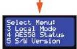
3 Local Mode menu 50
4 48 V Control....50
5 AESSO Status menu .... 51
6 Reset All menu.... S2
Appendix E XL8 Live Performance System.... 81 Appendix F Setting Up An XL8 System .... 128
Features 81
System components (standard supply) 82
System interconnections....83
FOH and MON 84
Mix matrix 85
Processing....85
Input channel processing 85
Mix channel processing 86
Output channel processing 86
Effects processing and GEQs.... 86
Audio physical connections.... 86
Uses of the configurable audio connections....87
Surround capabilities....88
Network 88
Resilience to failure (redundancy) 88
Control software....92
GUI 92
Console linking....92
Integration of third party software 92
DL431 Introduction
EN 1. Introduction
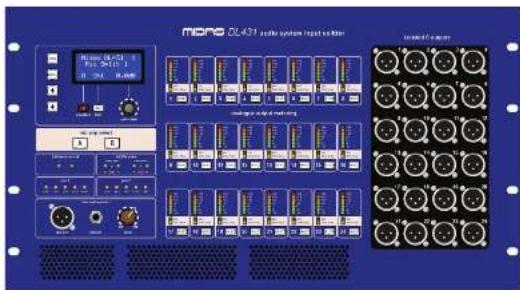
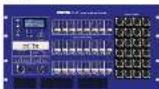
The DL431 Mlc Splitter is a six-unit (5U), high 19" rack unit that provides 24 mlc/ line inputs. Each input feeds three separate pramps, two of which have separate remote and local gain controls, while the third has fixed gain. The two pramps with gain controls feed separate analogue to digital (AVD) converters, which pass digital audio to the network. Four discrete AES50 outputs supply dual redundant digital audio to front of house (FOH) and monitor XL8 systems, and allow for easy routing to any third-party AES50 device, such as a recorder, via DL461 routers.
Two balanced analogue splits — sourced from post-each mic amp — are provided on the rear panel. The third preamp (fixed gain) feeds a transformer isolated split on the front panel for recording or broadcast applications.
Front panel control and local monitoring, including integral headphone amplifier, enhance the DL431's features, and dual redundant internal power supplies ensure worry-free operation. Four DL431s are supplied with each XL8 system to provide 96 input channels.
Your DL431 Mic Splitter was conceived by Mildas to offer audio professionals high-performance audio equipment, designed to provide no-compromise sonic quality with a feature set that offers all essential facilities and functions. It represents the very best of British design and engineering combined with contemporary, efficient manufacturing methods, and will give you many years of reliable service.
So, to obtain the best results with a minimum of effort, please read this operator manual and, finally, enjoy your Midas 01.431 Mic Splitter
Features
The DL431 Mic Splitter comprises:
- 24 micriline inputs.
- Three totally independent preamps per channel.
• Analogue spits.
• Full metering on every channel. - Hi pass 30 Hz filter option on every channel.
-
48 V phantom voltage option on every channel.
-
Control panel, with LCD screen, for easy unit configuration and channel set up.
- Two power supply units (PSUs) for dual redundancy.
• Easy routing to third-party AES50 devices. - Integral headphone amplifier.
About this manual
This is the operation manual for the DL431 Mic Splitter. It is intended to help get your DL431 Mic Splitter installed and in operation as quickly as possible by giving you unpacking, installation, connection, programming, setting up and operating instructions. To help familiarise you with the DL431 Mic Splitter there is a description of the front and rear panels.
The DL431 Mic Splitter forms an integral part of the XL8 Live Performance System. The appendices in this manual contain a brief overview of the XL8 Live Performance System and include system interconnection details. However, if you want to learn more about the XL8 Live Performance System, see the Owner's Manual (part number DOC02-91.B), which provides a full and comprehensive guide.
Intended readers
This manual is aimed at professionals, such as front of house (FCH) and monitor (MON) engineers who will be using this equipment in a live performance environment. It is assumed that the reader has prior experience of using professional audio equipment and has, most likely, undergone training on this system.
However, if you have limited experience on using this type of equipment, perhaps it might be useful to read through the pertinent sections in the user documentation for the XL8 Live Performance System before using this equipment. This will provide you with valuable background information.
Package contents/unpacking
Please retain the original packing for use should you need to transport or ship this unit.
After unpacking, please inspect the unit carefully for any signs of damage that may have occurred in transit and notify the courier immediately if you feel that any damage has occurred.
The following items are included in the DL431 Mic Splitter package:
• 1-off DL431 Mic Splitter Safety Sheet (part number D0C04-DL431).
- 1-off Warranty Card (part number DOOD-WARRANTY).
- 2-off mains leads (part number PWR21-MAINSLEADV).
ES 1. Introducción
EN DL431 Front Panel
EN 2. Front Panel
The front panel comprises the following:
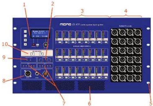
Control panel (see "Control panel" on page 4).
2 AESO audio panel monitors (see "MESO audio panel" on page 5).
① analogue output metering section (see "analogue output metering section" on page 6).
4 isolated C outputs section (see "isolated C outputs section" on page 6).
⑤ Eight cut-outs for rack mounting fixings.
Air intakes for fan cooling. Do not obstruct.
Power supply unit monitoring panels psu 1 and psu 2 (see "psu 1 and psu 2 panels" on page 5).
③ channel monitor panel (see "channel monitor panel" on page 5).
☐ Ethernet control panel (see "Ethernet control panel" on page 4).
⑪ mic amp select panel (see "mic amp select panel" on page 4).
23 DL451 Mic Splitter User Manual
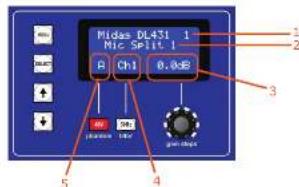
Control panel
The control panel has an LCD screen that is used with the three controls underneath (two buttons and a control knob) for controlling the input channel. In
programming mode the LCD screen shows the menus, which are navigated and selected using the tour. The controls in the control panel are backlit and illuminate to show when they are on or when pressed.

① LCD screen, comprising 64 characters (4 x 16). The default screen (shown typically above) is displayed during normal operation.
② gain steps control knob, for continuous gain adjustment within the range -2.5 dB to +45 dB.
(1) 30 Hz switch, switches the 30 Hz analogue high pass filter (HPF) on/off.
48V switch for switching the 48V phantom voltage on/off.
1 Programming buttons (see "Menu navigation" on page 13).
mic amp select panel

The mic amp select panel has two buttons, A and B, for selecting mic amp A or mic amp B. Both buttons have a blue backlight that illuminates to show that its mic amp is selected.
Ethernet control panel
The Ethernet control panel has two green LEDs, X and Y, which indicate network communication status, where:

- Flashing - active master.
- Illuminated - connected.
- Extinguished - not connected.
AES50 audio panel
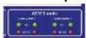
In the AESO panel, each X and Y channel — on both the A and B mic amp sections — has a green ok LED and red error LED, which illuminate when communications to these channels is ok or that there is an error, respectively.
psu 1 and psu 2 panels
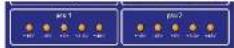
These panels monitor the DI-4TI Mic Splitter's internal supply voltages for each network. Theyellow LEDs illuminate to show that their respective voltage rails are active. The voltages are +38 V, -18 V, +5 V, +3.3 V and +48 V.
24 DL/3 Mic Splitter User Manual
EN
DL431 Front Panel
channel monitor panel
The channel monitor panel lets you connect headphones and listen to the audio of the selected input channel.
ES
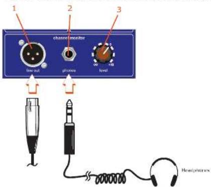
1 Female XLR line out socket. This monitor line output operates at unity gain in relation to any input signal applied and has a nominal operating level of 0 dBu. (Unlike the headphone jack this output does not have an independent level control.)
☐ phones socket for connection of a set of headphones.
[3] level control knob for adjustment of the headphones in the range = (Infinity) to +10 dB.
analogue output metering section
The analogue output metering section has 24 panels each of which monitors a specific analogue output channel.
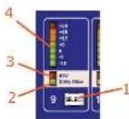
① SELECT switch for selecting the channel; illuminates green to show when channel is selected.
① 30 Hz filter on a:IF LED indicator; illuminates green to show that it is on for that channel.
① 48 V phantom voltage on/off LED indicator: illuminates red to show that it is on for that channel.
☐ Seven-segment LED meter displays the output level in the range -18 dB to +24 dB in 6 dB steps.
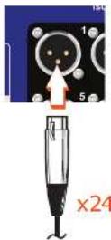
Isolated C outputs section
This section contains 24 isolated output sockets for connection of female XLR connectors, typically used for broadcast leads.
25 DL451 Mic Splitter User Manual
ES 2. Panel frontal
DL431 Front Panel DL431 Rear Panel
PL 2. Przedni panel
Panele psu 1 i psu 2
The rear panel comprises the following:
- Two banks of 24 output (A and B) XLR connectors (female).
• Bank of input XLR connectors (male). - Two sets (for dual redundancy) of mains IEC sockets and on/off switches.
Two USB connectors (host and slave).
- Three pairs of EtherCon® XLR connectors:
- One pair of connectors for 'tunnelling Ethernet'.
Two pairs of connectors (AESSO A and B) for audio and control data to/from the router.
34 DL/5 Mic Splitter User Manual
EN
DL431 Rear Panel
ES
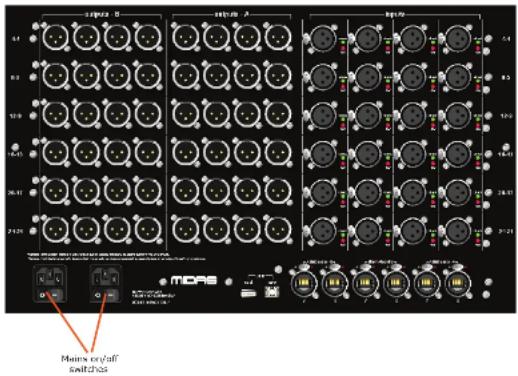
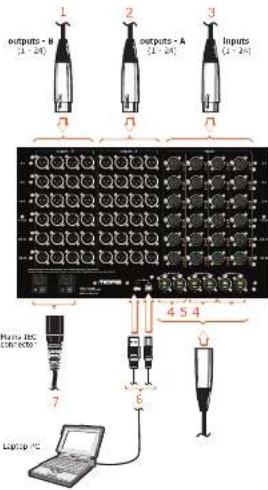
Rear panel connections
(7) outputs B section contains 24 sockets (6 x 4) for connection of XL R female connectors. Each row is numbered right to left in ascending order. Rows are in ascending order from top down.
② outputs A section contains 24 sockets (6 x 4) for connection of XLR female connectors. Each row is numbered right to left in ascending order. Rows are in ascending order from top down.
inputs section contains 24 sockets (6 x 4) for connection of XLR female connectors. Each row is numbered right to left in ascending order. Rows are in ascending order from top down.
Y and X AES50 audio - A and B EtherCon® XLRs for passing audio and control data to/from router. For a description of the LEDs, see "LED indicators" on page 9
[5] Y and X Ethernet control EtherCon® XLRs for connection of 'tunneling' Ethernet. For a description of the LEDs, see "LED Indicators" on page 9.
USB slave (type B) and host (type A) sockets for connection of a laptop PC.
☐ Two mains IEC sockets with on/off switches. Although both are connected to the mains, one is a dual redundant spare that can automatically switch in if the other fails.
FR
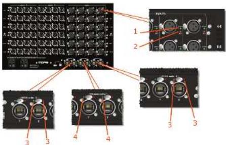
LED indicators
☐ Green check LED illuminates to show when a channel is selected on a console.
☐ Red 48 V LED illuminates to show that 48 V phantom voltage is on.
5 Green and red LEDs on both the X and Y AES50 audio - A and B sockets, indicate the following:
- Pulsating green with red extinguished = valid audio and valid aux data; active link.
- Constantly illuminated green with red extinguished = valid audio and valid audio data; standby ink.
- Green extinguished with red illuminated = no audio; link has failed.
4 Green LEDs on both the Ethernet control X and Y sockets have the same function as those in the Ethernet control panel on the front of the unit (see "Ethernet control panel" on page 4).
35 DL451 Mic Splitter User Manual
ES 3. Panel trasero
① Green check LED illuminates to show when a channel is selected on a console.
2 Red 48 V LED illuminates to show that 48 V phantom voltage is on.
(3) Green and red LEDs on both the X and Y AES50 audio - A and B sockets, indicate the following:
- Pulsating green with red extinguished = valid audio and valid aux data; active link.
- Constantly illuminated green with red extinguished = valid audio and valid aux data; standby link.
- Green extinguished with red illuminated – no audio; link has failed.
(4) Green LEDs on both the Ethernet control X and Y sockets have the same function as those in the Ethernet control panel on the front of the unit (see "Ethernet control panel" on page 4).
DL431 Getting Started
EN 4. Getting Started
This section shows you how to connect up, switch on, set up and configure the BL431 Mix Splitter. For operating instructions, see Chapter 6 "Operation".
Connecting up
Connect up your DL 431 Mic Splitter as follows:
- Inputs - connect the inputs to the rear of the unit.
- Outputs - connect the A and B outputs to the rear of the unit.
- AES50 - connect the Ethernet cables from the routers to the AES50 audio - A and AES50 audio - B X and Y sockets on rear of the unit.
- Ethernet - connect the Ethernet control cables to the rear of the unit.
- USB - connect a laptop/PC, if required, to the rear of the unit.
• Isolated C outputs - connect the isolated C outputs to the front of the unit. - Mains power supply - insert the IEC connectors of the two mains cables into the rear of the unit and then plug them both into mains power outlets.
Switching on/off

Caution!
itching the unit on/off, press the two mains on/off switches one after the other. Do not press them simultaneously.
After you have connected up your 01.417 Mic Splittee it is ready to be switched on. To do this, switch on both mains on/off switches on the rear of the unit, one after the other. At the front of the unit, check that the LEDs in panels psu 1 and psu 2 are all illuminated, see "psu 1 and psu 2 panels" on page 5.
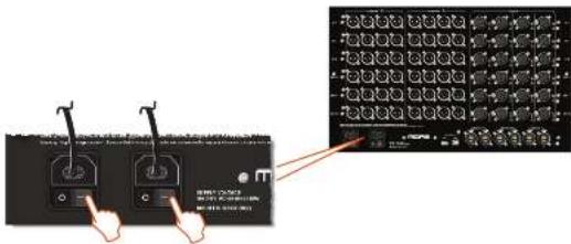
To switch off the DL431 Mic Splitter, switch off the two mains on/off switches on the rear of the unit, one after the other.
Setting up
Initial setting up of the DL4B1 Mic Splitter involves allocating an ID for it within the XL8 network system environment (see "To set up the unit's ID" on page 17).
Configuration
See Chapter 5 "Programming Mode" for configuration details.
41 DL-151 Mic Splitter User Manual
ES 4. Empezando
DL431 Getting Started
DE 4. Einstieg
EN DL431 Getting Started
SE 4. Komma igång
DL431 Programming Mode
EN 5. Programming Mode
This chapter describes the programming mode of the DL431 Mic Splitter.
In programming mode the four programming buttons in the control panel are used to navigate and select options from a number of menus (see "Menus" on page 16), which let you set up the unit and view information.
Menu navigation
The four programming buttons in the control panel have the following functions.
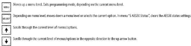
Moves up a menu level. Exits programming mode, depending on the current menu level.
Depending on menu level, moves down a menu level or selects the current option. In menu "S AES50 Status", clears the AES50 status settings.
Scrolls through the current level of menus/options.
+ Scrolls through the current level of menus/options in the opposite direction to the up arrow button.
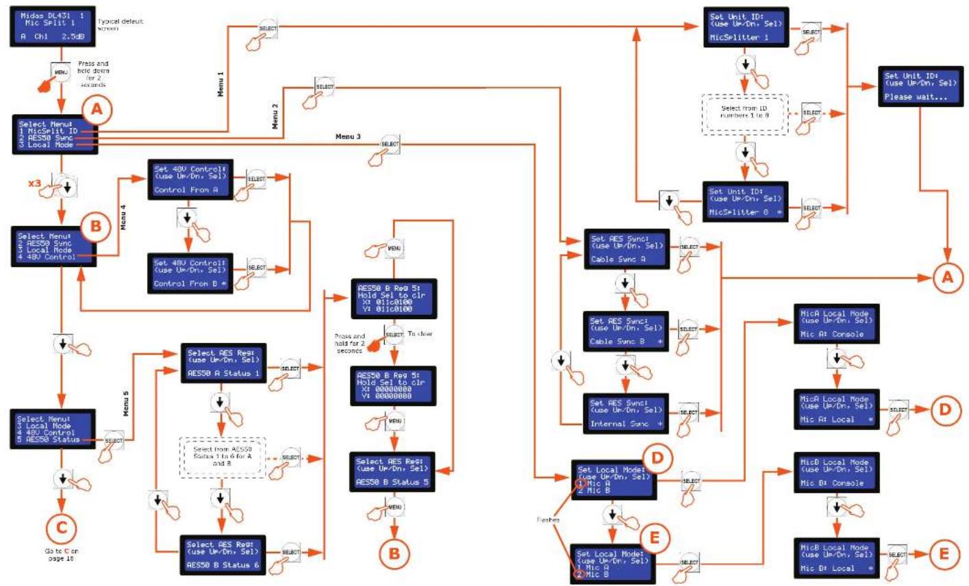
The menu flowchart (see "Menu flowchart (menus 1 to 5)", on page 14 and "Menu flowchart (menus 6 and 7)", on page 15) gives an overview of all the menus and their options, and shows you how to navigate your way around them. When navigating the menus, notes that menus are shown on the left, and each subsequent lower level of each menu is to the right; an asterisk (*lower-right corner) means that the option is not the currently selected one; and flashing options (far left character) are currently selected.
>> To enter/exit programming mode
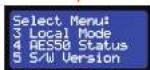
To enter programming mode from any menu display screen, press the MENU button and hold down for approximately two seconds; the default display will change to the "Select Menu" display (see display A on page 14).
To exit programming mode, press MENU repeatedly until you reach the default screen. The DL431 Mic Splitter will exit programming mode automatically after about 20 seconds of inactivity, that is, if none of the programming buttons are pressed within that time.
>> To select a menu
In the "Select Menu" display, scroll to the menu you want by using the up/down arrow buttons; its number will flash to show that it is currently selected. Then, press SELECT.
EN
SE
PL
46 DL/3 Mic Splitter User Manual
47 DL/51 Mic Splitter User Manual
EN DL431 Programming Mode
Menu flowchart (menus 1 to 5)
flowchart
graph TD
    A["Select Menu 1\nMicSplit ID\n2 RES50 Sync\n3 Local Mode"] --> B["A"]
    B --> C["Menu 1"]
    C --> D["Select Menu 4\nRES50 Sync\nLocal Node 48V Control"]
    D --> E["B"]
    E --> F["Menu 4"]
    F --> G["Set 48V Control\n(use Up/Dr, Sel)\nControl From A"]
    G --> H["Menu 5"]
    H --> I["Select Res Rst\n(use Up/Dr, Sel)\nRES50 A Status 1"]
    I --> J["Menu 6"]
    J --> K["Go to C on page 10"]
    K --> L["C"]
    L --> M["Select Menu\nLocal Node 48V Control\nRES50 Status"]
    M --> N["Menu 5"]
    N --> O["Select Res Rst\n(use Up/Dr, Sel)\nRES50 B Status 6"]
    O --> P["Menu 6"]
    P --> Q["Select Res Rst\n(use Up/Dr, Sel)\nRES50 B Status 5"]
    Q --> R["Menu 6"]
    R --> S["Select Res Rst\n(use Up/Dr, Sel)\nRES50 B Status 4"]
    S --> T["Menu 6"]
    T --> U["Select Res Rst\n(use Up/Dr, Sel)\nRES50 B Status 3"]
    U --> V["Menu 6"]
    V --> W["Select Res Rst\n(use Up/Dr, Sel)\nRES50 B Status 2"]
    W --> X["Menu 6"]
    X --> Y["Select Res Rst\n(use Up/Dr, Sel)\nRES50 B Status 1"]
    Y --> Z["Menu 6"]
    Z --> AA["Select Res Rst\n(use Up/Dr, Sel)\nRES50 B Status 0"]
    AA --> AB["Menu 6"]
    AB --> AC["Select Res Rst\n(use Up/Dr, Sel)\nRES50 B Status 0.1"]
    AC --> AD["Menu 6"]
    AD --> AE["Select Res Rst\n(use Up/Dr, Sel)\nRES50 B Status 0.2"]
    AE --> AF["Menu 6"]
    AF --> AG["Select Res Rst\n(use Up/Dr, Sel)\nRES50 B Status 0.3"]
    AG --> AH["Menu 6"]
    AH --> AI["Select Res Rst\n(use Up/Dr, Sel)\nRES50 B Status 0.4"]
    AI --> AJ["Menu 6"]
    AJ --> AK["Select Res Rst\n(use Up/Dr, Sel)\nRES50 B Status 0.5"]
    AK --> AL["Menu 6"]
    AL --> AM["Select Res Rst\n(use Up/Dr, Sel)\nRES50 B Status 0.6"]
    AM --> AN["Menu 6"]
    AN --> AO["Select Res Rst\n(use Up/Dr, Sel)\nRES50 B Status 0.7"]
    AO --> AP["Menu 6"]
    AP --> AQ["Select Res Rst\n(use Up/Dr, Sel)\nRES50 B Status 0.8"]
    AQ --> AR["Menu 6"]
    AR --> AS["Select Res Rst\n(use Up/Dr, Sel)\nRES50 B Status 0.9"]
    AS --> AT["Menu 6"]
    AT --> AU["Select Res Rst\n(use Up/Dr, Sel)\nRES50 B Status 1.0"]
    AU --> AV["Menu 6"]
    AV --> AW["Select Res Rst\n(use Up/Dr, Sel)\nRES50 B Status 1.1"]
    AW --> AX["Menu 6"]
    AX --> AY["Select Res Rst\n(use Up/Dr, Sel)\nRES50 B Status 1.2"]
    AY --> AZ["Menu 6"]
    AZ --> BA["Select Res Rst\n(use Up/Dr, Sel)\nRES50 B Status 1.3"]
    BA --> BB["Menu 6"]
    BB --> BC["Select Res Rst\n(use Up/Dr, Sel)\nRES50 B Status 1.4"]
    BC --> BD["Menu 6"]
    BD --> BE["Select Res Rst\n(use Up/Dr, Sel)\nRES50 B Status 1.5"]
    BE --> BF["Menu 6"]
    BF --> BG["Select Res Rst\n(use Up/Dr, Sel)\nRES50 B Status 1.6"]
    BG --> BH["Menu 6"]
    BH --> BI["Select Res Rst\n(use Up/Dr, Sel)\nRES50 B Status 1.7"]
    BI --> BJ["Menu 6"]
    BJ --> BK["Select Res Rst\n(use Up/Dr, Sel)\nRES50 B Status 1.8"]
    BK --> BL["Menu 6"]
    BL --> BM["Select Res Rst\n(use Up/Dr, Sel)\nRES50 B Status 1.9"]
    BM --> BN["Menu 6"]
    BN --> BO["Select Res Rst\n(use Up/Dr, Sel)\nRES50 B Status 2.0"]
    BO --> BP["Menu 6"]
    BP --> BQ["Select Res Rst\n(use Up/Dr, Sel)\nRES50 B Status 2.1"]
    BQ --> BR["Menu 6"]
    BR --> BS["Select Res Rst\n(use Up/Dr, Sel)\nRES50 B Status 2.2"]
    BS --> BT["Menu 6"]
    BT --> BU["Select Res Rst\n(use Up/Dr, Sel)\nRES50 B Status 2.3"]
    BU --> BV["Menu 6"]
    BV --> BW["Select Res Rst\n(use Up/Dr, Sel)\nRES50 B Status 2.4"]
    BW --> BX["Menu 6"]
    BX --> BY["Select Res Rst\n(use Up/Dr, Sel)\nRES50 B Status 2.5"]
    AX --> BZ["Set Unit ID\n(use Up/Dr, Sel)\nMicSplitter 1"]
    YZ --> AB["Set Unit ID\n(use Up/Dr, Sel)\nMicSplitter 1.1 to 3"]
    AB --> AC["Set Unit ID\n(use Up/Dr, Sel)\nMicSplitter 1.2 to 4"]
    AC --> AD["Set Unit ID\n(use Up/Dr, Sel)\nMicSplitter 1.3 to 5"]
    AD --> AE["Set Unit ID\n(use Up/Dr, Sel)\nMicSplitter 1.4 to 6"]
    AE --> AF["A"]
    AF --> AG["A"]
    AG --> AH["Set Unit ID\n(use Up/Dr, Sel)\nPlease wait..."]
    AH --> AI["D"]
    AI --> AJ["NicA Local Mode\n(use Up/Dr, Sel)\nNic At Console"]
    AI --> AK["NicA Local Mode\n(use Up/Dr, Sel)\nNic At Local*"]
    AK --> AL["NicB Local Mode\n(use Up/Dr, Sel)\nNic By Console"]
    AL --> AM["NicB Local Mode\n(use Up/Dr, Sel)\nNic By Local*"]
    AM --> AN["NicB Local Mode\n(use Up/Dr, Sel)\nNic By Local*"]
EN
48 DL/5 Mic Splitter User Manual
EN DL431 Programming Mode
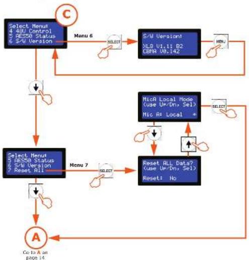
Menu flowchart (menus 6 and 7)
flowchart
graph TD
    A["Select Menu 4.420 Control 5.658 Status 6.540 Version"] --> B["Menu 6"]
    B --> C["S/U Version: NLD U1.t1 B2 DBR U0.i42"]
    C --> D["Menu"]
    D --> E["Select Menu 5.420 Status 6.540 Version 7 Reset RII"]
    E --> F["Menu 7"]
    F --> G["Reset ALL Data? (use Up/Down, Sel) Reset: No"]
    G --> H["Co to A on page 14"]
    H --> I["A"]
    I --> J["Select Menu 4.420 Control 5.658 Status 6.540 Version"]
    J --> K["Menu 7"]
    K --> L["Reset ALL Data? (use Up/Down, Sel) Reset: No"]
    L --> M["Co to A on page 14"]
Menus
Programming mode has the following menus:
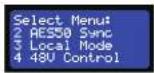
- 1 MicSplit ID - for setting up the DL431 Mic Splitter's network unit ID (see "1 MicSplit ID menu" below).
- 2 AES50 Sync – for selecting the method of synchronising the AES50 (see "2 AES50 Sync menu" on page 17).
- 3 Local Mode – for setting up mode type (see "3 Local Mode menu" on page 18).
- 4.48 V Control - for selecting the 40 V phantom voltage source (see "4.48 V Control" on page 19).
- S AESO Status – for viewing clearing the AESO values (see "S AESO Status menu" on page 19).
- 6 S/W Version – for displaying the host software and CBMA versions that the unit is currently running.
- 7 Reset All – resets all settings to default (see "7 Reset All menu" on page 20).
49 DL-161 Mic Splitter User Manual
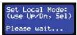
1. MicSplit ID menu
This menu lets you setup the network ID of the DL431 Mix Splitter. There are eight ID numbers available.
To set up the unit's ID
-
In programming mode, select menu 1 (see "To select a menu" on page 13).
-
Use the up/down arrow buttons to choose the ID number you want, for example, mic splitter ID 2.
-
Press SELECT
-
In exit programming mode, press MENU. The default display will now show the newly configured ID.
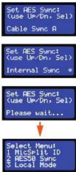
2. AES50 Sync menu
>> To set up the unit's AES50 synchronisation
This menu lets you set up the clock source for AESO synchronisation of the DL-131 Mic Splitter, and has the following options:
- Cable Sync A - if using the FOH console's clock as the AES50 master
• Cable Sync B – if using the MON console's clock as the AES50 master.
- Internal Sync – for stand alone operation and test purposes.
1. In programming mode, select menu 2 (see "To select a menu" on page 13).
2. Use the up/down arrow buttons to choose the source of AES50 synchronisation for the unit, for example, internal synchronisation.
3. Press SELECT
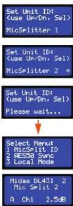
flowchart
graph TD
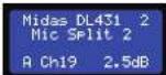
A["Set Unit ID: (use Up/Dn, Sel) MicSplitter 1"] --> B["Set Unit ID: (use Up/Dn, Sel) MicSplitter 2 *"]
B --> C["Set Unit ID: (use Up/Dn, Sel) Please wait..."]
C --> D["Select Menu\n1 MicSplit ID\n2 RE50 Sync\n3 Local Mode"]
D --> E["Midas DL431 2 Mic Split 2\nA Ch1 2.5dB"]
50 DL/3 Mic Splitter User Manual
EN DL431 Programming Mode
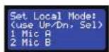
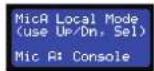
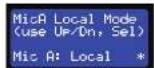
3. Local Mode menu
This menu has the following options for setting up the DL431 Mic Splitter for local/console operation:
- Local – allows gain and function changes from the unit's control panel (see "Control panel" on page 4). Both mic amps, A and B, can be operated locally.
- Console — locks out the gain and pushbuttons on the control panel, and only allows changes from the connected console. Only mix amp A can be operated from the connected console.
>> To set up the unit for local or console operation
-
In programming mode, select menu 3 (see "To select a menu" on page 13).
-
Press the up/down arrow button to select the mic amp (A or B), for example, mic amp A. The number on the left will flash to show which mic amp is currently selected.
-
Press the up/down arrow button to choose the option you want, for example, local.
4. Press SELECT.
If you didn't change selection, the display shown right will be missed out.
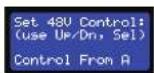
4.48 V Control
This menu lets you set the 48 V phantom voltage source.
To select the 48 V phantom voltage source for the unit
-
In programming mode, select menu 4 (see "To select a menu" on page 13).
-
Press the up/down arrow buttons choose the source of the 48 V phantom voltage, for example, mic amp B.
-
Press SELECT.

51 DL451 Mic Splitter User Manual
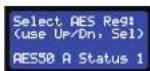
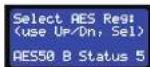
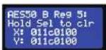
5. AES50 Status menu
This menu lets you view/clear the ACS50 status of the DL431 Mic Splitter.
To view/clear the AES50 status
-
In programming mode, select menu 5 (see "To select a menu" on page 13).
-
Press the up/down arrow buttons to choose the AESO display you want, for example, "AESO B Status S".
3. Do one of the following
• To clear the values, press SELECT.
Note: You can only clear the X and Y values for AES50 Reqs when you see the message "Hold Sel to dir" on line 2 of the display. This message typically does not appear on Status 3 and 4 displays.
• If you don't want to dear the values, press MENU.

52 DL/3 Mic Splitter User Manual
EN DL431 Programming Mode
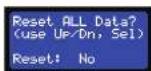
- Reset All menu
This menu lets you set all of the DL431 Mix Splitter's settings to default. For example, it will set the ID number to 1, 48 V control from A, all gains to 0 dB etc.
Important:
Use this menu with caution. Make sure you really want to reset all settings to default before proceeding.
To reset all settings to default
-
In programming mode, select menu 7 (see "To select a menu" on page 13).
-
Press the up arrow button. (Pressing the down arrow will display the "No" option.)
-
Do one of the following:
• To reset all settings to default, press SELECT.
- If you don't want to clear the values, press MENU.


53 DL451 Mic Splitter User Manual
DL431 Programming Mode
DL431 Programming Mode
DL431 Programming Mode
DL431 Programming Mode
DL431 Programming Mode
1. MicSplit ID-menu
This menu lets you set all of the DL431 Mic Splitter's settings to default. For example, it will set the ID number to 1, 48 V control from A, all gains to 0 dB etc.
Belangriik:
DL431 Programming Mode
4.48 V kontroll
5. AES50 Status-meny
DL431 Programming Mode
This chapter shows you how to operate the D431 Mic Splitter.
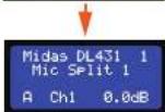
Default display
The default display appears after the unit has been switched on and has powered up. The following diagram shows a typical default display. The first line of text displays the company name, model of the unit and the user-configured ID number.
(1) The second line of text displays the unit name followed by the
② user configured ID number (see "To set up the unit's ID" on page 18).
③ Current gain value of the selected channel [see "To adjust the gain" on page 26].
4 Number of the currently selected channel (see "To select a channel" on page 24).
5 Mic amp source identifier (see "To select a mic amp" on page 24).
Adjusting a channel
The following instructions show you how to adjust a channel on the DL431 Mic Spitter, and are in the recommended order of operation, as follows:
- Select mic amp (A or B).
- Select a channel
- Switch 48 V phantom voltage on/off.
- Switch 30 Hz filter on/off.
- Adjust the gain.
>> To select a mic amp
In the mic amp select panel (see "mic amp select panel" on page 4), press A or B to select the mic amp you want. The button will illuminate to indicate selection.
>> To select a channel
In the analogue output metering section (see "analogue output metering section" on page 6), select the channel you want by pressing its SELECT button. The button will illuminate to indicate selection.
>> To switch on the 48 V phantom voltage
With your channel selected, as shown on the LCD screen, press 48 V in the control panel to switch the 48 V phantom voltage on/off. The red 48 V LED in the channel's panel of the analogue output metering section (see "analogue output metering section" on page 6) will illuminate when the 48 V phantom voltage is on.
>> To switch on the 30 Hz filter
With your channel selected, as shown on the LED screen, press 30 Hz in the control panel to switch the 30 Hz filter on/off. The green 30 Hz LED in the channel's panel of the analogue output metering section (see "analogue output metering section" on page 6) will illuminate when the 30 Hz filter is on.
>> To adjust the gain
With your channel selected, as shown on the LCD screen, adjust the gain steps control knob on the control panel to achieve the desired gain. The current value will be shown on the LCD screen.
Monitoring a channel
You can listen to a channel on a pair of headphones. To do this, plug the headphones into the phones socket of the channel monitor panel (see "channel monitor panel" on page 5). Adjust the signal level to suit, using the level control knob.
ES 6. Operación
EN Using the 30 Hz filter
The DL431 Mic Splitter's 30 Hz filter is an analogue high pass filter (IIFF). It is a very low frequency signal filter with a 30 Hz corner frequency and 12 dB per octave Butterworth roll off. This filter can be switched into circuit following the mic amp to make better use of the analogue-to-digital (A/D) conversion headroom by removing the very low frequency audio content.
High pass filters are used to remove unwanted subsonic frequencies, which are traditionally about 30 Hz. A typical use for this filter is to reduce rumble.
Appendix C: Technical Specification
This appendix contains the technical specifications specific to the DL431 Mic Splinter. For full technical specifications for the XL8 Live Performance System, see the owner's manual (part number DOC02-XLB).
Due to a policy of continual improvement, Midas reserves the right to alter the function or specification at any time without notice.
General specifications
| Dimensions 50 x 410 mm deep |
| Net weight 21.5 kg |
| Power requirements 100 V to 240 °C, 30 to 50 Hz |
| Operating temperature range +5°C to -40°C |
| Storage temperature range -20°C to +50°C |
Inputs and outputs
Analogue Inputs
| Connector 3-pin ALB balanced | |
| Phantom power 18-watt with local switch and remote control 5 am ALB control centre | |
| Gain control A 2.5 dB to -45 dB multiple gain in 2.5 dB steps with local and remote control pass a further ±20 dB offi resolution interpolated DSP trim | |
| Gain control B Independent second channel identical to above | |
| Filter A | 30 dB high pass with local defeat switch and remote control from ALB control centre |
| Filter B | Independent second channel identical to above |
| Meter (24-off) 7 segments, 18 dB to +24 dB | |
| Meter A/B | Meters can be switched to resonance A or B pre amplifiers |
| A/D converter A | 24-bit, 96x and 128 times over sampling |
| A/D converter B | Independent second channel identical to above |
Analogue outputs
| Connector A | 3-pin XLR balanced |
| Connector B | Independent second channel identical to above |
| Connector C | Independent third channel on front-mounted 3-pin XLR, balanced and transformer isolated width (used gain of -6 ds) |
| Headphone connector | 5" jack |
| Audio monitor | 3-pin XLR balanced |
Digital (system) outputs
| System connector A | AES50 124 channels of digital audio on Ethercon XLR |
| System connector B | Independent second channel identical in above |
| Duplicate connector A | AES50 124 channels of digital audio on Ethercon XLR providing dual redundant back up of a channels |
| Duplicate connector B | AES50 124 channels of digital audio on Ethercon XLR providing dual redundant back up of B channels |
EN
EN
Appendix D: Service Information
ES
This appendix gives you servicing information for your unit.
If you are in any doubt or have queries about any of the procedures in this appendix, contact Midas Technical Support. Contact details can be found at the front of this manual.
Routine maintenance
To help keep your unit in good working order and to make sure it gives you optimum performance, we recommend that you carry out the following:
Monthly
- Clean the unit, as detailed in "Cleaning" below.
• Check all controls, such as pushbuttons, for freedom of operation. - Check the functionality of all controls and indicators, such as LEDs.
- Check the functionality of the equipment.
Yearly
- Clean the internal fans, see "Cleaning the internal fans" below.
Cleaning
Switch off the unit and electrically isolate it from the mains before cleaning.
Clean the unit using a dry, lint-free cloth. Don't use harsh abrasives or solvents. When cleaning the unit, take great care not to damage the controls or LCD screen.
Cleaning the LCD screen
Carefully wipe the surface of the LCD screen with a soft, lint-free cloth using ethanolic liquid, such as a screen cleaner for LCDs, or by using a screen wipe specially designed for the purpose. When cleaning the LCD screen, please take the following precautions:
- Don't use harsh abrasives, such as paper towels.
- Don't apply liquids directly to the screen.
• Don't use ammonia-based cleaners and solvents, such as acetone.
Cleaning the internal fans
The unit's internal fans need to cleaned regularly to remove the build of dust, dirt etc. We recommend that they are cleaned at least once a year, provided the unit has been operated under normal conditions. However, if the operating conditions are more adverse or extreme, for example, if the unit is operated in the vicinity of smoke machines, new carpets etc., this frequency should be increased accordingly.
This procedure must be carried out by a fully qualified service engineer.
Appendix D: Service Information
(1) The XL8 Live Performance System is a very powerful and flexible audio processing system that provides a complete solution for any audio mixing and signal distribution application in a live sound environment.
The standard XL8 system offers 96 channel inputs, 51 outputs, 51 buses (32 auxes/groups, 16 matrices and three masters), 16 on-board effects processors, PEOs (four-band on inputs and six band on outputs), up to 48 assignable GEOs (of all stereo effects units are being used), 16 configurable stereo effects (from eight options), surround panning (5.1, LCRS and quad) and comprehensive, easy-to-use routing. XL8 automation provides up to 1,000 scenes with snapshot save/recall capability and global edit, presets and show file archiving.
The XL8 Control Centre forms the core of the XL8 Live Performance System, which also includes a number of 19" rack modules that are interconnected by a networked data system. The network carries both proprietary control data and open architecture AT550 digital audio, and uses readily available standard cabling and connectors. The XL8 uses the proven stable Linux operating system. Third party hardware and software (and plug-ins) can be easily integrated into the system.
Included with the XL8 Control Centre are four mic splitters, five I/O units, 10 DSP units, two routers and a Klark Teknik DN9331 RAPIDE that, collectively, form the standard XL8 Live Performance System configuration.
The XL8 Live Performance System is tolerant of any single failure of hardware or software. To achieve this the system employs dual redundancy, where a key component has an identical redundant spare that is ready to take over should it fail. Other failure scenarios are managed by the N4-1 principle, where redundant components form an acceptable fraction of the system, for example, one of the DSP units in the rack is a redundant spare.
Features
Please remember, the XL8 is not just a console, it's a LIVE PERFORMANCE SYSTEM!
Concert sound
The standard XL8 system, which provides the full 96 inputs and
51 outputs, comprises:
• 1-off XL8-5 BCC (flight-cased, five-bay control centre).
4-off XL8 stage box (DL431).
5-off XL8 (I/O box (DL451).
• 10-off XL8 DSP units (DL471).
2-off XL8 router units (DL461).
- All interconnecting cables (Cat 5e and Cat 6).
install
The XL8 is flexible and the system can be customised with the needs of the install.
Configuration
• All outputs have six-band parametric EQ and five-mode compressor styles.
- Up to 16 stereo FX units.
• Up to 48 assignable GEQs (16 if all 16 stereo FX units are being used).
• Control from RAPIDE.
Showfiles
-
- USB connectors for show archiving.
• Showfiles are both forward and backward compatible
- USB connectors for show archiving.
Audio quality
- Three mic pre amps per input FOH, monitor and broadcast.
- Midas EQ (sound quality and 'feel').
• Four filters.
v • Midas dynamics.
• Four styles (five on outputs).
- + Midas quality input and output.
- Midas and Klark Teknik FX processing.
User interface - speed and feel
- + VCA groups.
- Console comes to you!
c + POP groups.
- Console comes to you!
- Muscle memory.
• E-zone on channel strip.
- D-zone on channel strip.
- Paged controls do not change function.
← Fast zone.
Electronic colour coding.
- Dedicated motorised output faders.
- + Klark Teknik RAPIDE.
User Interface - status visibility
- Daylight-visible screens.
- Metering
- 63 discrete 20-segment LED meters.
• Discrete metering for dynamics and direct outputs.
… “All the meters all of the time”.
- "ST" assign switch.
• Eight channels of key data plus single channel strip per input screen.
Dual operators - perfect for festival situations
- Modular control centre with multiple input areas.
- Area A and Area B assignment.
- Discrete dual solo systems.
Automation - developed in conjunction with Broadway
sound designers and engineers
- Cross-the global hit caprumbly.
• Showifies on earlier and later versions of firmware.
System design and network - ground-breaking
• Integrated analogue mic splits with local control and monitoring.
- Integrated open architecture AES50 digital audio distribution.
- Fully duplicated networks for redundancy.
- Up to 100 metres of dual redundant connectivity between hardware
elements (copper); up to 500 metres using optical fibre.
• Automatic integral delay management system - audio outputs time and phase coherent.
- Flexible, expandible hardware system.
- Ethernet TCP-IP and USB tunneling for third parties.
- KVM (keyboard, video and mouse) switching on control centre.
Reliability
- Failure-tolerant of any single failure of hardware or software.
- Proven, stable Linux operating system.
• Duplicated master controllers.
• Control centre has five multiple-redundant power supplies.
• Stage box has integral dual power supplies.
Service and support
• 24/7 global telephone support.
• Service/support centres in US, UK and Singapore.
System components (standard supply)
The standard XL8 Live Performance System comprises the following equipment:
- XL8 Control Centre (1-off): Comprises five discrete, independent bays, each with its own power supply, surface modules, surface processor, GUI processor and GUI screen. The standard five-bay control centre has three bay types, input (3-off), mix (1-off) and output (1-off).
- DL431 Mic Splitter (4-off): 6U 19^ rack unit that provides 24 mic/line inputs.
- DL451 Modular I/O (5-off): 30 19" rack unit that provides a maximum of 24 audio inputs and 24 audio outputs.

- DL471 DSP (10-off): 1U '19" rack unit that forms part of the modular DSP engine.

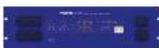
- DL461 Router (2-off): 3U 1V rack unit that provides the on-stage Cat Se interconnectivity and the stage-to-FOH link via a single 'snake', which can be copper cable or a fibre optic link.
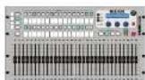
- Klark Teknik DN9331 RAPIDE (1-off): 6U 19" rack unit that is a motorised faster remote control for the onboard graphic EQs of the XL8.
• Snakes and main cables etc.
To provide a complete audio system, the only other equipment required are mics, amplifiers and loudspeakers.
83 DL451 Mic Splitter User Manual
System interconnections
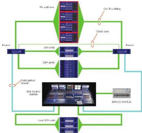
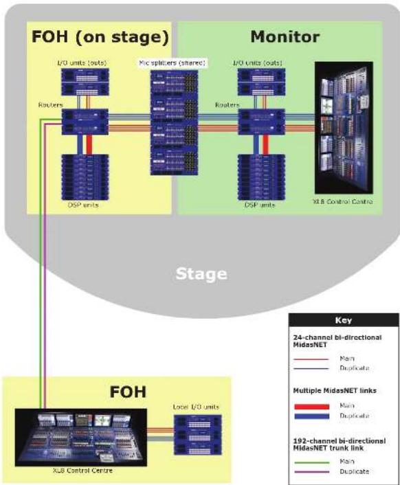
Figure 1 shows basic system interconnectivity and indicates where the XL8 Control Centre (highlighted in red) sits within the system. This figure also illustrates redundancy by showing that the two halves of the system - left and right - are identical (ignoring the DM9331 RAPIDE).
The XL8 Control Centre, which forms the core of the XL8 Live Performance System, is directly connected to the local I/O units, DN9331 RAP/DE and routers (via the "snake"). Each router acts as a hub and is connected to the mic splitters I/O units and DSPs, which are common to both halves of system. The network carries both proprietary control data and open architecture AES50 digital audio, and uses readily available standard Cat 5c, Cat6/fibre optic cabling and connectors.
flowchart
graph TD
    A["Router"] --> B["1/0 units"]
    B --> C["DSP units"]
    C --> D["XLB Control Centre"]
    D --> E["DR9J31 RAPDC"]
    E --> F["Local I/O units"]
    F --> G["Clock sync"]
    G --> H["No spulators"]
    H --> I["Cut 5x cabling"]
    I --> J["Router"]
    style A fill:#f9f,stroke:#333
    style D fill:#ccf,stroke:#333
    style E fill:#cfc,stroke:#333
Figure 1: Basic interconnectivity of a standard XL8 Live Performance System
EN
84 DL/5 Mic Splitter User Manual
EN Appendix E: XL8 Live Performance System
FOH and MON
The XL8 Live Performance System can be used as a front of house (FOI) or stage monitor (NOK) system. Also, by sharing the four mix splitters, these two types of system can be used in tandem, as shown in Figure 2 on page 36.
Figure 4 on page 43 shows in more detail the interconnections between each unit in a typical XL8 Live Performance System FOH and MON set up. In particular, it shows the how the FOH and MON sections are connected up: notice that the mic splitters are shared between them.
flowchart
graph TD
    subgraph FOH (on stage)
        A["L/O units (outs)"] --> B["Routers"]
        B --> C["DSP units"]
        D["Mic splitters (shared)"] --> E["Routers"]
        E --> F["DSP units"]
        G["L/O units (outs)"] --> H["Routers"]
        H --> I["DSP units"]
        J["XLB Control Centre"] --> K["Local L/O units"]
    end

    subgraph Monitor
        L["L/O units (outs)"] --> M["Routers"]
        M --> N["DSP units"]
        O["XLB Control Centre"] --> P["Local L/O units"]
    end

    style FOH (on stage) fill:#f9f9f9,stroke:#333
    style Monitor fill:#e6f7ff,stroke:#333
Figure 2: Typical XL8 Live Performance System FOH and MON set-up
85 DL451 Mic Splitter User Manual
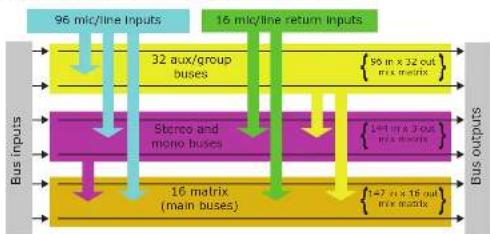
Mix matrix
Ultimately, the mix matrix defines the XL8 Control Centre's capability. Probably the best way to imagine the mix matrix is to think of an analogue console layout, where inputs run vertically and buses run horizontally. A mix matrix is usually defined as the number of buses and the quantity of simultaneously mixable inputs there are per bus. The following diagram illustrates the capability within the control centre.
flowchart
graph TD
    A["Bus inputs"] --> B["96 mic/line inputs"]
    B --> C["32 aux/group buses"]
    C --> D["16 matrix (main buses)"]
    D --> E["16 mic/line return inputs"]
    E --> F["Bus outputs"]
    subgraph Bus inputs
        G["Stonce and mono buses"]
        H["16 matrix (main buses)"]
    end
    subgraph Bus outputs
        I["96 in x 32 out flux matrix"]
        J["147 in x 18 out flux matrix"]
    end
Processing
Although the control centre system allows for considerable insertion of external processing it also embodies more than enough internal high quality processing to eliminate the need for this.
Input channel processing
Each of the 96 full-function input channels has:
- Analogue and digital gain.
- Phase reverse switch.
• Input delay.
- Swept high pass filter with choice of two filter slopes.
- Swept low pass filter with choice of two filter slopes.
• Frequency-conscious compressor with choice of four compression styles.
• Frequency-conscious noise gate with external side chain.
- Insert point.
- Treble EQ filter with choice of four filter types.
- Parametric hi-mid EO filter.
- Parametric lo-mid EQ filter.
- Bass EQ filter with choice of four filter types.
- Routing via level controls to 48 m/s buses.
- Riouting via pan control to left and right master buses.
- Routing to mono master bus.
- Panper (SIS ^TM ).
- Direct output.
86 DL/5 Mic Splitter User Manual
EN Appendix E: XL8 Live Performance System
Each of the 16 auxiliary inputs has:
• Input gain.
- Source from internal FX or external pool input.
Fader.
• Panpot (SIS).
- Routing via level controls to the 15 matrix buses.
- Routing via pan control to the left, right and mono master buses.
Mix channel processing
Each of the 32 auxiliary mix buses has:
- Subgroup, auxiliary or mix minus modes.
- Dual mono or stereo pair modes.
- Six-band PEQ.
• Optional 31-band GEO (replaces PEO). - Frequency-conscious compressor with soft clip limiter and choice of five compression styles.
• Insert point - Routing via level controls to the 15 matrix buses.
- Routing via pan control to the left, right and mono master buses.
- Direct Input.
Each of the 16 matrix buses has:
Six-band PEQ.
• Optional 31-band GEQ [replaces PEQ]. - Five-mode frequency-conscious compressor with soft clip limiter and external side chain.
- Insert point
- Direct input.
Output channel processing
Each of the 16 matrix buses has:
Six-band PEO.
- Optional 31 band GEO (replaces PEO).
- Five-mode frequency-conscious compressor with soft clip limiter and external side chain.
- Insert point.
- Direct input.
Each of the three master output buses has:
- Six-hand PEQ.
- Optional 31-band CEQ (replaces PEQ).
- Fire-mode frequency-conscious compressor with soft clip limiter and external side chain.
• Insert point. - Direct input.
Effects processing and GEQs
The XL8 contains 16 mono Klark Teknik (KT) GEOs and 16 effects processors as standard.
The 16 effects processors can be freely chosen from:
- Delay.
• KTON780 reverb. - Flanger.
• Phaser.
• Stereo-Graphic EQ. - Pitch shifter.
• Square ONE Dynamics. - 3-band compressor.
The 16 mono KT GEOs can be patched into any output. There are many patching options for the effects processors:
- Assign to any insert send/return.
- Assign to any pool, in or out.
- Assign FX out to auto return.
- Assign FX in to aux send (post-fade).
- Assign FX out to bus direct in.
- Assign FX in to channel direct out.
Every XL8 comes supplied with a KT DN9331 RAPIDE motorised fader GEO controller. This unit provides rapid adjustments of the graphics with real hardware, and not a mouse and screen. The graphic channel is selected either by the control centre's SOLO button (solo tracking system [STS]) or by buttons on the RAPIDE itself.
Audio physical connections
The total number of audio connections, that is, the XLR count, for a standard XL8 Live Performance System is 504. This comprises of both dedicated and configurable XLR connections.
The dedicated XL-R connections are on the DL431 mic splitter and comprise:
- 96-off micrline inputs.
- 2 x 96 off analogue mic splits with variable gain
- 95-off transformer isolated analogue 'broadcast' mic splits (fixed gain).
All of the configurable connections are on the five DL451 I/O units, which can be freely located at the FOH or on stage. Three banks of sockets (eight XLRs each) are available for: - 8-off analogue micr-line inputs.
- 8-off analogue outputs.
- 8-off AES/EBU XLRs providing eight digital inputs and eight digital outputs per module.
87 DL451 Mic Splitter User Manual
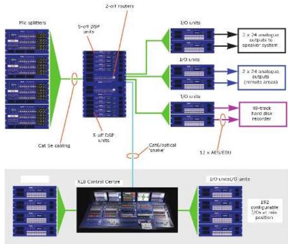
Uses of the configurable audio connections
The standard XL8 Live Performance System has a total configurable audio channel count (on the DL451 I/O units) of between 120 and 240, depending on the mix of analogue and digital I/O (excluding the non-configurable 9% mic inputs on the DL431 mic splitter).
Typically, the allocation would be:
• 16-off mic/line auxiliary inputs (giving a total of 112 mic inputs as standard).
• 32-off axx/group bus outputs.
- 16-off matrix (main) outputs.
1-off stereo main output.
- 1-off mono main output.
- 2-off stereo local monitor outputs.
This gives a total of 71 audio connections, leading a further 169 (with everything digital) or 49 (with everything analogue) audio connections. These can be used for insert sends, insert returns, direct outputs, bus direct inputs and side chain connections.
flowchart
graph TD
    A["Mix splitters"] --> B["Cat 5e cooling"]
    B --> C["5-off DSP units"]
    C --> D["2-off routers"]
    D --> E["I/O units"]
    E --> F["2 x 24 analogue outputs to speaker system"]
    D --> G["I/O units"]
    G --> H["2 x 24 analogue outputs (remote areas)"]
    D --> I["I/O units"]
    I --> J["18-track hard disk recorder"]
    C --> K["Cath/optical 'snake'"]
    K --> L["XLB Control Centre"]
    L --> M["I/O units/I/O units"]
    M --> N["192 configurable (I/Os at mix position)"]
Figure 3: XL8 maximum system capacity (112 mic inputs)
88 DL/3 Mic Splitter User Manual
EN Appendix E: XL8 Live Performance System
The maximum count of any one type of connection is:
- % off input insert sends.
- 96-off input insert returns.
-
- %-off input compressor external side chain connections.
- 96-off input noise gate external side chain connections.
- 96-off input direct outputs.
-
- .51-off mix bus insert sends.
- 51-off mix bus insert returns.
- 51-off mix bus direct inputs.
• 1-off talk mic input.
However, the XL8 can have much more than the standard connectivity by adding DL451 I/O units. As there are nine AES30 connections ^1 (fully redundant) available, potentially, another 432 audio connections can be achieved (subject to other system limits). This gives a maximum XLR count of 720. Figure 3 shows a system configuration containing the extra nine DL451 I/O units, but does not show the redundant duplicated network.
All connectivity is controlled via the GUI.
Surround capabilities
Theatres and broadcast have differing requirements for surround, and both are catered for in the XL8.
Conventional stereo and SIS ^™ panning is assignable on a channel by channel basis (channel one can be in stereo while channel two can be in SIS ^™ ), as follows:
- Stereo left-right routing to master buses.
- SIS™ left-right-centre routing to master buses.
Three additional surround modes operate as follows: - Quad felt, right, LS and RS].
- Surround (left, right, centre, surround).
- 5.1 surround (left, right, centre, subwoofer, LS and RS).
Network
The XL8's digital audio network utilises the physical connectivity of Ethernet (EtherCon® connectors and Cat Se/Cat6 cable), but replaces its data protocol with AES50 protocol (Implemented as SuperMAC) and the HyperMAC high capacity system, which are more suited to high quality, low latency audio distribution. The use of the AES standard allows straightforward interfacing with any third party hardware that also utilizes this connection.
AESSO and HyperMAC connections carry digital audio, control data and standard Ethernet traffic by directionally down a single cable. Cat 5c cable is used for the local (24-channel) connections and the single digital "smoke" — between control centre and router — is either Cat 5e/Cats or fibre optic. The combination of audio, control, clock and third party Ethernet data in a single network means that the hardware interfaces on a single R45 connection.
-
These spare AESSD ports can also be used to directly connect any AESSD equipped units, such as a hard disk recorder.
-
The digital snake is equivalent to a 384-channel analogue multi-core cable (192 channels in each direction).
All system connections are duplicated for full dual redundancy.
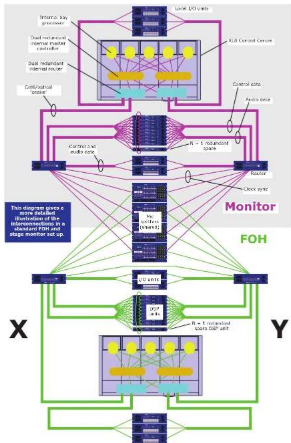
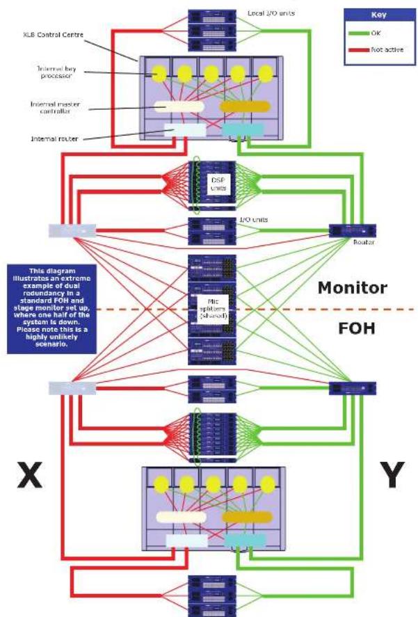
Resilience to failure (redundancy)
The XL8 Live Performance System is tolerant of any single failure of hardware or software. To achieve this the system employs dual-redundancy, where a key component has an identical redundant spare that is ready to take over should it fail. Other failure scenarios are managed by the K+1 principle, where redundant components form an acceptable fraction of the system; for example, one of the DSP units in the rack is a redundant spare (see Figure 4 on page 43).
The control surface can tolerate multiple hardware failures without the operator losing control of the audio. Any of the live GII screens can be used to operate the whole control centre, even if no control surface hardware is working.
The system includes diagnostic tools that give advance warning of any poor connectivity (high error rates), internal temperatures and voltages etc. The system instantly alerts the operator in the event of any hardware, software or connection failures, and indicates the location of the fault. The system asks the operator what action to take, but doesn't automatically reconfigure. This is so that it, for example, the band is near the end of a song and the audio is still alright, the mir engineer carry out corrective action at a more opportune time.
Figure 5 on page 44 shows that even when all of one half of the system is down (the greyed out portion) it will still function as normal. Although, in practice, it is highly unlikely that this will ever happen.
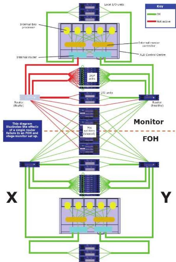
Figure 6 on page 90 illustrates what happens when a router fails. Once again, the system functions perfectly normally.
89 DL451 Mic Splitter User Manual
flowchart
graph TD
    subgraph FX8 Control Centre
        A["Local I/O units"] --> B["Control data"]
        B --> C["Audio data"]
        C --> D["Control and audio data"]
        D --> E["Monitor"]
        E --> F["FOH"]
        F --> G["I/O units"]
        G --> H["DSP units"]
        H --> I["N = 1 redundant spare DSP unit"]
    end
    subgraph FOH
        J["Micro SPUTS (ensed)"] --> K["Clock sync"]
    end
    subgraph Monitor
        L["Control data"] --> M["Control and audio data"]
        M --> N["Control and audio data"]
        N --> O["Control and audio data"]
        O --> P["Control and audio data"]
        P --> Q["Control and audio data"]
        Q --> R["Control and audio data"]
        R --> S["Control and audio data"]
        S --> T["Control and audio data"]
        T --> U["Control and audio data"]
        U --> V["Control and audio data"]
        V --> W["Control and audio data"]
        W --> X["Control and audio data"]
        X --> Y["Control and audio data"]
        Y --> Z["Control and audio data"]
        Z --> AA["Control and audio data"]
        AA --> AB["Control and audio data"]
        AB --> AC["Control and audio data"]
        AC --> AD["Control and audio data"]
        AD --> AE["Control and audio data"]
        AE --> AF["Control and audio data"]
        AF --> AG["Control and audio data"]
        AG --> AH["Control and audio data"]
        AH --> AI["Control and audio data"]
        AI --> AJ["Control and audio data"]
        AJ --> AK["Control and audio data"]
        AK --> AL["Control and audio data"]
        AL --> AM["Control and audio data"]
        AM --> AN["Control and audio data"]
        AN --> AO["Control and audio data"]
        AO --> AP["Control and audio data"]
        AP --> AQ["Control and audio data"]
        AQ --> AR["Control and audio data"]
        AR --> AS["Control and audio data"]
        AS --> AT["Control and audio data"]
        AT --> AU["Control and audio data"]
        AU --> AV["Control and audio data"]
        AV --> AW["Control and audio data"]
        AW --> AX["Control and audio data"]
        AX --> AY["Control and audio data"]
    end
    subgraph FOH
        AZ["V/O units"] --> BA["Clock sync"]
    end
    subgraph Monitor
        BB["X"] --> BC["This diagram gives a more detailed illustration of the interconnections in a standard FDH and stage monitor set up."]
    end
    subgraph FOH
        BD["X"] --> BE["N = 1 redundant spare DSP unit"]
    end
    subgraph Monitor
        BF["Y"] --> BG["N = 1 redundant spare DSP unit"]
    end
Figure 4: System interconnections
90 DL/5 Mic Splitter User Manual
EN Appendix E: XL8 Live Performance System
flowchart
graph TD
    subgraph Local I/O Units
        A["Local I/O units"] --> B["Local I/O units"]
        C["Local I/O units"] --> D["DSP Units"]
        E["Local I/O units"] --> F["I/O Units"]
        G["Local I/O units"] --> H["Router"]
    end

    subgraph DSP Units
        I["DSP Units"] --> J["I/O Units"]
        K["I/O Units"] --> L["Router"]
    end

    subgraph I/O Units
        M["I/O Units"] --> N["Router"]
    end

    subgraph Monitor FOH
        O["Monitor FOH"] --> P["Marker FOH"]
    end

    style Local I/O Units fill:#f9f,stroke:#333
    style DSP Units fill:#ccf,stroke:#333
    style I/O Units fill:#cfc,stroke:#333
    style Router fill:#fcc,stroke:#333
    style Monitor FOH fill:#ffc,stroke:#333
    style X fill:#fff,stroke:#333
    style Y fill:#fff,stroke:#333
Figure S: System showing 50% redundancy
91 DL451 Mic Splitter User Manual
flowchart
graph TD
    subgraph Key
        A["Local I/O units"] --> B["Internal bay processor"]
        A --> C["Internal router"]
        B --> D["Internal master controller"]
        C --> D
        D --> E["XLB Control Centre"]
        E --> F["DCP units"]
        F --> G["L/O units"]
        G --> H["Router (healthy)"]
        H --> I["Monitor FOH"]
        I --> J["Micro circuitors (shared)"]
    end

    subgraph X
        K["Router (Realty)"] --> L["Local I/O units"]
        K --> M["Local I/O units"]
        L --> N["Local I/O units"]
        M --> O["Local I/O units"]
        N --> P["Local I/O units"]
        O --> Q["Local I/O units"]
    end

    style Key fill:#90EE90,stroke:#333
    style X fill:#0066CC,stroke:#333
    style Y fill:#0066CC,stroke:#333
    style Monitor fill:#FFD700,stroke:#333
    style FOH fill:#FFD700,stroke:#333
Figure 6: System with a redundant router
EN
EN
Appendix E: XL8 Live Performance System
Control software
The XLR's operating system is Linux, which is an open source, stable, proven operating system (OS). Linux is used in many mission critical applications worldwide and has allowed Mides' software engineers to write a ground-up system that contains no 'hidden' or unused code. This has resulted in an efficient, compact application, which is quick in operation, quick booting and comparatively easy to debug.
Two copies of the master control software run on separate processors to provide resilience to failure.
GUI
The XL8 has five, daylight-viewable, TFT screens that provide overview and detail status indication. Any screen can display any information but, in the standard configuration, screen information relates to module location. So, the input module screens display their module's input status, the mix module screen displays the overview status screen (all the motors all the time) and the output module screen display is used for general use, such as automation, effects, GEOs, third party screens etc. This is dependent on the current application (concerts will probably be different to theatre), and also operator preference.
The screens are controlled via the navigation zones at the front of the modules. In the output module's primary navigation zone, two trackballs control the output module (right trackball) and the mix module (left trackball). The equivalent on each input module is a dedicated flickpad. A keyboard slides out from underneath the output module to provide further control, such inserting text. USB keyboard input sockets at the front of the control centre (under the left and right modules) allow the input and mix screens to be controlled via an external keyboard should the output module screen fail.
Console linking
Two XL8 Control Centres can be linked together, as you can with Heritage consoles. The bus outputs from one control centre feeds the bus inputs of the other, which is done using AES50 links.
Integration of third party software
The XL8 network includes the capability to interface any third party hardware that uses AES/EBU or AESSO digital audio, or a standard analogue audio interface.
Each XL8 AES/EBU input and output has a sample rate converter. Synchronisation to external AES3 interfaces can be:
- Global - via Inputs on the routers.
- Local to each input.
- Local to each output (synchronisation to adjacent local output).
Multiple local connections can be at different sample rates.
The use of the A1550 protocol for the transmission of digital audio means that any third party digital audio hardware that features this connection can be connected to the Midas network, and will transfer audio to and from the Midas hardware without any additional interfaces or converters (provided it runs in TDA 96 kHz mode). This will be particularly useful as the protocol gains acceptance with recording and playback devices, loudspeaker controllers, audio networking systems, digital amplifiers etc.
PC or MAC computers can use the Ethernet tunnel in the MidasNET system, and can communicate with other computers on the network.
Integration of third party software 47
The XL8 Control Centre features a four-way KVM switch on the output module screen, as well as external video IN and OUT for each of the five screens. Control centre views can be routed to external monitors, and external video sources can be displayed on the control centre's screens.
The KVM switch facilitates the control of three external computers from the screen, trackball and keyboard of the control centre. This is hugely important and means that third party systems can be controlled from within the XL8 without having to move your head to look at screens placed off to one side. It also means that there is no need to find somewhere to put multiple keyboards and mice. Examples are:
• ProTools. Right in the middle of the XL8! Link ProTools and XLS audio digitally and use any ProTools plug-in as an insert to the XL8!
- Netmax (AES/EBU audio link initially and Cobranet when the 48 kHz I/O module is available on XL8).
- IRIS (for example, for RL amps).
• KT Elgar (via Ethernet tunnel from FOII to stage).
- * Wireless mic controllers.
- Your email.
• DVD movies.
Service et assistance
- 96-off-input-insert-Sends.
- 4-off XL8 stage box (DL431).
- 5-off XL8 [O box (D,457).
Assegna FX in a aux send (post-fade).
- + Surround (sinistra, destra, centro, surround).
- Surround 5.1 (sinistro, desiro, centrale, subwoofer, LS e RS).
Rete
- Tot 16 stereo FX-units.
- 63 discrete 20-segments LED-meters.
- 51-off mix bus insert sends.
- + 51-off mix bus insert retourneert.
- + 51-off mixbus directe ingangen.
- 1-off talk microfooningang.
- • Surround (links, rechts, midden, surround).
- 5.1 surround (links, rechts, midden, subwoofer, LS en RS).
Netwerk
- Event is on acc filter mod 10.24
- That the investment is the first investor.
The following table is in Chinese:
• Part of Schools.
- * Panpot (SIS ^® ).
samplingstrekwelster.
This chapter shows you how to set up an XL8 Live Performance System to its default configuration.
Note: if you want to set up the XL8 Live Performance System using a configuration other than the default, please contact Midas Technical Support for details.
Initial set-up procedure
Initial system set-up basically comprises:
- Unpacking and checking the equipment — see "Unpacking the equipment" below.
• Making up the racks — see "Making up the racks" below. - Connecting up the equipment — see "Wiring instructions" on page 51 and "XLS system interconnections" on page 54.
- Powering the equipment — see "Powering the XLS system" on page 57.
- Initial patching:
- Configure the type of snake — see "Configuring the XL8 with the snake type" on page 30. It is important to configure the XL8 with the correct type of snake connected in the system.
- Setting up the I/O rack devices — see "Configuring the devices" on page 29.
- Configuring the DL4n1 units — see "Setting up the ID of the DL4n1 units" on page 59.
Unpacking the equipment
After carefully unpacking the equipment, check it against the packing list shown in "System components (standard supply)" on page 34.
Save all packing materials, as they will prove useful if you need to transport the equipment later.
Inspect the equipment carefully for any sign of damage incurred during transportation. It has undergone stringent quality control inspection and tests prior to packing and was in perfect condition when it left the factory. However, if the equipment shows any signs of damage, notify the transportation company without delay. Only you, the consignee, may institute a claim against the carrier for damage during transportation.
Making up the racks
After you have unpacked the XL8 Live Performance System and made sure everything is there, make up the racks. In the default set up there are three stage rack units and one FOH rack unit, which should be set up as shown in "XL8 system interconnections" on page 54.
Although rack unit set-up is fairly straightforward, there are careful considerations to be addressed beforehand, which are outlined in the following subsections.
Outboard equipment racks
To ensure the correct installation and function of the outboard equipment, such as the DL4n1 units and DK9696 recorder, the racks must meet the following general requirements.
- Shock mounting (for non-installation environments): The racks must provide adequate shock protection of the units they house by incorporating appropriately-designed shock protection methods, for example, a foam-suspended rack or a frame suspended on anti-vibration mounts etc.
- Ventilation: The XL8 rack units have been designed such that their internal ventilation airflow is drawn in through the front of the unit and expelled through the rear. To facilitate this, rack design must ensure that orol air can flow freely through the rack in the same direction, that is. In through the front of the rack and out through the rear. Situations where the air flows in a circular direction around and through an XL8 unit must be prevented. Midas recommends that racks with fully opening front and rear doors are used.
Note: Never combine units in the same rack that have been designed for a ventilation air flow direction other than that for the XL8 units. To avoid this, we recommend that any non-XL8 units are housed separately. - Rack mount supports: Always secure the rear of the XL8 units to the rack via their rear rack mount support brackets. These brackets are fitted to every XL8 unit and are recommended for use in touring applications. The rack mount support fixing hole centres are at a depth of approximately 395 mm from the front panel [this dimension may differ slightly on the CNP956].
- Handles on rack case: You must ensure that there are sufficient external handles fitted to the rack casing to enable the rack to be manoeuvred easily and safely, and by the amount of personnel suitable for the task. Also, these handles must be fit for purpose.
- DSP rack only: Midas strongly recommends that the DSPs and routers are housed in a single rack, that is, stage rack 2 (see "Stage rack 2" on page 51). This rack can be either a 16U high (minimum) rack or configured as an 8II double rack.
- Clearance at rear of units: To ensure an adequate clearance at the rear of the units, we recommend that the rack depth, that is, the distance from the front rack strip to the rear of the rack, is a minimum of 700 mm. This is to provide sufficient free space to enable the DSP link cables to achieve their minimum bend radius.
- Securing the cables: We recommend that the cables at the rear of the units be ticked using facing bars and cable ties. This should provide optimum access to the rear of the units for connecting other cables, switching the units on/off etc., and give maximum visibility of the units' LEDs for determining communication status, link status, condition of audio etc. The picture (right) shows a good example of how this can be done. For more information on cabling, refer to "Stage rack 2" on page 51.
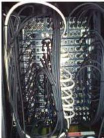
natural_image
Interior view of an electronic equipment rack with exposed wiring and circuitry (no visible text or labels)Stage rack 2
Stage rack 2, also known as the "DL461/DL471 engine rack", contains the two routers and 10 DSP units.
Important:
In general, the physical location of the hardware units within each rack is not critical, and alternative configurations are acceptable for different packaging preferences. However, best practice is to mount the DL471 units in numerical order, which will aid quick identification and fault finding.
DL471 unit ID numbers are located on stickers on the top cover of each device and also on the carton. These must be noted prior to build-up and connected, as shown, in numerical sequence. Please note that once initially configured, the ID numbers are displayed on the top row of the DL471 screen and role numbers are on the bottom row. The role numbers are dynamic and, therefore, may change during system operation.
Wiring instructions
This section gives the system cabling details for the 30.8-specific equipment and, although it is laid out in recommended order, this order is not critical.
When making the connections, please make sure they match those in "XL8 system interconnections" on page 54. Further details are shown in "Cable type and function" on page 56.
>> To connect both routers together
Important:
Without this connection system snake redundancy will be compromised.
Connect the routers via their Ethernet socket of the control expansion section on each router's rear panel (see "System interconnection panel" on page 253).
>> To connect the XL8 to the routers
Connect the 'snake' [optical or copper] from the X snake socket on the rear of the XL8 Control Centre to the appropriate snake socket on the X Router. Repeat for the Y Router using the Y socket on the XL8 Control Centre.
>> To connect the routers to the DSPs (Stage rack 2)
>> To connect the routers to the Stage rack 1 units
- In AES50 audio - bank 0 on the X router, connect the 10 sockets to the AES50 audio X socket on the DSP units. Repeat for the Y router, using the equivalent Y sockets.
- In Ethernet control bank on the X router, connect the 10 sockets to the Ethernet control X socket on the DSP units. Repeat for the Y router, using the equivalent Y sockets.
- Mic splitters: In AES50 audio - bank 1 on the X router, connect sockets 1 and 2 to the AES50 audio - A X sockets on the Mic Splitters. Repeat for Y router, using the mic splitters' Y sockets.
- Line I/O units: In AES50 audio - bank 1 on the X router, connect sockets S and S to the AES50 audio X sockets on the line I/O units. Repeat for Y router, using the line I/O units' equivalent Y sockets.
EN
>> To connect the routers to the Stage rack 3 units
- Mic splitters: In AES50 audio - bank 1 on the X router, connect sockets 3 and 4 to the AES50 audio - A X sockets on the mic splitters. Repeat for the Y router, using the mic splitters' Y sockets.
- Line I/O unit: in AES50 audio - bank 1 on the X router, connect socket 6 to the AES50 audio X socket on the line I/O unit. Repeat for the Y router, using the line I/O units' equivalent Y socket.
>> To connect the XLS to the line I/O units (FOH rack)
Connect the AES50 audio X sockets on the rear of the XL8 Control Centre to the AES50 audio X socket on both of the line I/O units in the FOH rack. Repeat for the Y sockets.
>> To connect the XL8 to the RAPIDE
Connect one of the eight ETHERNET (EtherCon" XLR) sockets on the rear of the RAPIDE unit to the Ethernet control 1 socket of the active network (X or Y) on the rear of the XL8 Control Centre (see "XLR system interconnections" on page 54).
130 131DL121 Mic Splitter User Manual DL/31 Mic Splitter User Manual
EN Appendix F: Setting Up An XL8 System
To daisy chain the DSP units
Important Note:
Do not connect a cable to like numbered sockets, that is, "0" to "0" or "1" to "1", as the DSPs will not work; socket numbers are printed to the right of each socket.
There are two default configurations available, depending on the lengths of the interconnecting DSP cables supplied, that is, 0.25 m cables or 0.5 m cables. Both options contain a long cable for connecting the top and bottom units, and the 0.25 m option has an additional long cable for connecting units ANU 2 and ANU 9.
A cable's length (cm) can be determined from a three-digit number contained within its part number (printed on a label attached to the cable). For example, in a part number of "14150-5788-050-01C 060425 7D" the "050" indicates a length of 50 cm.
Connect the DSPs together as shown in the following diagram, according to the cables supplied with your system. (In the diagram, the cables are coloured and the sockets numbered to help distinguish them.)
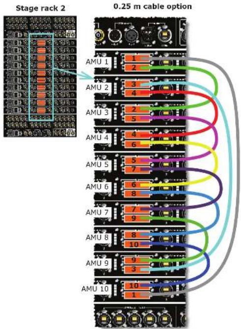
Figure 7: Stage rack 2 - DSP wiring options
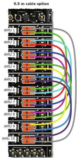
132 133DL131 Mic Splitter User Manual DL-31 Mic Splitter User Manual
EN
Appendix F: Setting Up An XL8 System
XL8 system interconnections
This diagram shows the network interconnections for a typical FOII XL8 system.
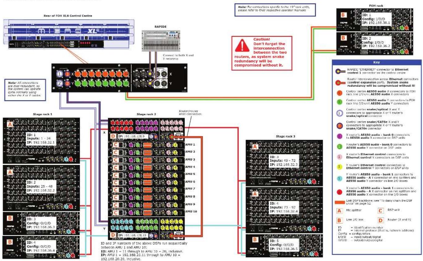
flowchart
graph TD
    A["FOH XL8 Control Centre"] --> B["Stage rack 1"]
    A --> C["Stage rack 2"]
    A --> D["Stage rack 3"]
    B --> E["AMU 1"]
    B --> F["AMU 2"]
    B --> G["AMU 3"]
    B --> H["AMU 4"]
    B --> I["AMU 5"]
    B --> J["AMU 6"]
    B --> K["AMU 7"]
    B --> L["AMU 8"]
    B --> M["AMU 9"]
    B --> N["AMU 10"]
    C --> O["AMU 1"]
    C --> P["AMU 2"]
    C --> Q["AMU 3"]
    C --> R["AMU 4"]
    C --> S["AMU 5"]
    C --> T["AMU 6"]
    C --> U["AMU 7"]
    C --> V["AMU 8"]
    C --> W["AMU 9"]
    C --> X["AMU 10"]
    D --> Y["AMU 1"]
    D --> Z["AMU 2"]
    D --> AA["AMU 3"]
    D --> AB["AMU 4"]
    D --> AC["AMU 5"]
    D --> AD["AMU 6"]
    D --> AE["AMU 7"]
    D --> AF["AMU 8"]
    D --> AG["AMU 9"]
    D --> AH["AMU 10"]
    E --> AI["FOH rack"]
    F --> AI
    G --> AI
    H --> AI
    I --> AI
    J --> AI
    K --> AI
    L --> AI
    M --> AI
    N --> AI
    O --> AJ["FOH rack"]
    P --> AJ
    Q --> AJ
    R --> AJ
    S --> AJ
    T --> AJ
    U --> AJ
    V --> AJ
    W --> AJ
    X --> AJ
    Y --> AJ
    Z --> AJ
    AA --> AJ
    AB --> AJ
    AC --> AJ
    AD --> AJ
    AE --> AJ
    AF --> AJ
    AG --> AJ
    AH --> AJ
    AI --> AK["Key"]
    AJ --> AL["RAPIDE "ETHERNET" connector to Ethernet control 1 connector on the control centre"]
    AK --> AM["Router interconnection across Ethernet connectors (control expansion port). System snake redundancy will be compromised without it!"]
    AK --> AN["Control centre AES50 audio X connectors to FOH rack line I/O unit AES50 audio X connectors"]
    AK --> AO["Control centre AES50 audio Y connectors to FOH rack line I/O unit AES50 audio Y connectors"]
    AK --> AP["Control centre snake/optical X and Y connectors to appropriate X or Y router's snake/optical connector"]
    AK --> AQ["Control centre snake/CAT6e X and Y connectors to appropriate X or Y router's snake/CAT6e connector"]
    AK --> AR["X router's AES50 audio - bank O connectors to AES50 audio X connector on DSP units"]
    AK --> AS["Y router's AES50 audio - bank O connectors to AES50 audio Y connector on DSP units"]
    AK --> AT["X router's Ethernet control connectors to Ethernet control X connectors on DSP units"]
    AK --> AU["Y router's Ethernet control connectors to Ethernet control Y connectors on DSP units"]
    AK --> AV["Y router's AES50 audio - bank I connectors to AES50 audio - A Y connector on mic splitters and AES50 audio Y connectors on line I/O boxes"]
    AK --> AW["X router's AES50 audio - bank I connectors to AES50 audio - A X connector on mic splitters and AES50 audio X connector on the I/O boxes"]
    AK --> AX["Link DSP backbone: see "To dairy chain the DSP units" on page 52"]
    AK --> AY["Mic splitter"]
    AK --> AZ["Line I/O box"]
    AK --> BA["D Router (X end Y)"]

    style A fill:#f9f,stroke:#333
    style B fill:#ccf,stroke:#333
    style C fill:#cfc,stroke:#333
    style D fill:#fcc,stroke:#333
    style E fill:#ffc,stroke:#333
    style F fill:#fcc,stroke:#333
    style G fill:#fcc,stroke:#333
    style H fill:#fcc,stroke:#333
    style I fill:#fcc,stroke:#333
    style J fill:#fcc,stroke:#333
    style K fill:#fcc,stroke:#333
    style L fill:#fcc,stroke:#333
    style M fill:#fcc,stroke:#333
    style N fill:#fcc,stroke:#333
    style O fill:#fcc,stroke:#333
    style P fill:#fcc,stroke:#333
    style Q fill:#fcc,stroke:#333
    style R fill:#fcc,stroke:#333
    style S fill:#fcc,stroke:#333
    style T fill:#fcc,stroke:#333
    style U fill:#fcc,stroke:#333
    style V fill:#fcc,stroke:#333
    style W fill:#fcc,stroke:#333
    style X fill:#fcc,stroke:#333
    style Y fill:#fcc,stroke:#333
EN
134 135DL121 Mic Splitter User Manual DL-31 Mic Splitter User Manual
EN Appendix F: Setting Up An XL8 System
Cable type and function
The following table shows the type, terminations and function of the XL8 system's interconnecting cables. Please read the table in conjunction with the network interconnections diagram on page 54.
| KEY | CABLE | FROM | TO | DESCRIPTION |
| Cat Se with Ethernet® XLRs | X Router (Ethernet connector in expansion port) | Y Router (Ethernet connector in expansion port) | Carries redundancy information for the digital video. | |
| Cat Se with Ethernet® XLRs | RAPOL (ETHERNET n connector) | Control centre (Ethernet control 1 connector) | Carries information on later positions. | |
| Cat Se with Ethernet® XLRs | Control centre (AESSO audio X connector) | (10 unit) (AESSO audio X connector) | Carries a b-directional combination of 24 channels of 36 MHz audio plus 5 bits of control data. | |
| Cat Se with Ethernet® XLRs | Control centre (AESSO audio Y connector) | (10 unit) (AESSO audio Y connector) | Carries a b-directional combination of 24 channels of 36 MHz audio plus 5 bits of control data. | |
| Optical smoke with Neural OpticalCon® connections | Control centre X/Y Router | Carries a bit-directional combination of 192 channels of 36 MHz audio plus 200 bits of control data. | ||
| Cat Se smoke with Ethernet® XLRs | Control centre Router Carries a bit-directional combination of 192 channels of 36 MHz audio plus 200 bits of control data. | |||
| Cat Se with Ethernet® XLRs | X Router (AESSO audio bank 1) | DSP (3): Carries a b-directional combination of 24 channels of 36 MHz audio plus 5 bits of control data. | ||
| Cat Se with Ethernet® XLRs | Y Router (AESSO audio bank 1) | DSP (3): Carries a bit-directional combination of 24 channels of 36 MHz audio plus 5 bits of control data. | ||
| Cat Se with Ethernet® XLRs | X Router (Ethernet control X) | DSP (3): Carries standard: 100 bus Fast Ethernet data. | ||
| Cat Se with Ethernet® XLRs | Y Router (Ethernet control X) | DSP (3): Carries standard: 100 bus Fast Ethernet data. | ||
| Cat Se with Ethernet® XLRs | Y Router (AESSO audio bank 0) | Mix splitter (7): | Carries a bit-directional combination of 24 channels of 36 MHz audio plus 5 bits of control data. | |
| Cat Se with Ethernet® XLRs | X Router (AESSO audio bank 0) | Mix splitter (3): | Carries a bit-directional combination of 24 channels of 36 MHz audio plus 5 bits of control data. | |
| 3M cable with 92-way connections | DSP (link 0) | DSP (link 0) | Carries a proprietary data format for connecting the DSP units together to form the DSP loop. | |
EN
Powering the XL8 system
The following details the recommended power up and power down procedures for the XLB system.
>> To power up the XLS system
Important Note:
DO NOT switch on the speaker sub-system until after the start-up of the XL8 system has been completed.
After all XL8 system interconnections have been made [see Chapter 30 "Panel Connections"], start up the XL8 system.
-
Make sure that all of the XL8 system equipment is switched off, that is, the XL8 Control Centre, speaker sub-system, DL-431 mic splitters, DL-451 modular line I/O units, DL-451 routers and DL-471 DSP units.
-
Switch on the XL8 Control Centre (see "To switch on the XL8 Control Centre" on page 58).
-
On the XLB Control Centre, move all of the monitor and master channel faders to the minimum position and mute all of the master channels. The master channels can be found in the mix and output fast zones (see "XLB control surface" on page 7).
-
Switch on the DL431 Mix Splitters.
-
Switch on the DL4S1 Modular I/O units.
-
Switch on the DL471 DSP units.
-
Switch on the DL461 Routers.
-
After the status LEDs (top of each GUI screen on the XL8 Control Centre) turn green, switch on the speaker sub-system.
-
Switch on the audio source and start playing the audio.
-
On the XL8 Control Centre, check that the audio inputs are routed to the master channels. Then, unmute the master channels and gradually increase their faders, while listening to the sound levels from the speakers.
If there are no sounds at all from the speakers when the leaders are at maximum, move the leaders to below the 0 dB level and check if the audio is muted somewhere along the input paths and also check that the individual speakers are switched on. If there is still no sound from the speakers, contact Midas Technical Support.
>> To power down the XL8 system
Important Note:
BEFORE switching off any of the XL8 system components, make sure to mute the audio from the speakers and switch off the speaker sub-system.
-
Mute the audio from the speakers and switch off the speaker sub-system.
-
Switch off the DL431 Mic Splitters.
-
Switch off the D1451 Modular I/D units.
-
Switch off the DL471 DSP units.
-
Switch off the DL461 Reuters.
-
Switch off the XL8 Control Centre (see "To switch off the XL8 Control Centre" on page 59).
136 137DL121 Mic Splitter User Manual DL-31 Mic Splitter User Manual
EN
Appendix F: Setting Up An XL8 System
Switching the XL8 Control Centre on/off
Carry out the following to switch the XL8 Control Centre on/off in a safe manner, observing all WARNINGS and Cautions.
To switch on the XL8 Control Centre
WARNING! DO NOT INSERT OR REMOVE A POWERCON® CONNECTOR INTO/FROM REAR OF CONTROL CENTRE WITH MAINS POWER AND ANY OF THE MAINS BAY SWITCHES ON. YOU MUST MAKE SURE ALL MAINS BAY SWITCHES ARE OFF AND MAINS IS SWITCHED OFF AT THE POWER OUTLET(S) FIRST.
Caution! Before switching on, check that all monitor loudspeaker power amplifiers are turned off or muted. After connecting up the audio cables, carry out the following:
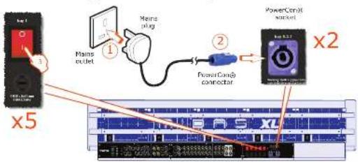
Rear of XL8 Control Centre
-
Plug the two control centre's mains PowerCon® cables into the mains power outlets.
-
Insert the two mains PowerCon® connectors into the PowerCon® sockets on rear of control centre, observing the WARNING! above. Then, lock each one by twisting the PowerCon® connector about 90° [1/4 turn] clockwise; you should hear a click when it has locked in place. Check that both PowerCon® connectors are securely fitted.
- Observing the Caution! above, switch on all five bay mains on/off switches, one after the other. It is important that you don't switch on two or more switches simultaneously.
- The control centre will power up; the GUI will display the default screens and all the controls will be set to default. You are now ready to start using the XL8 control centre.
To switch off the XL8 Control Centre
- Make sure you have saved any shows, scenes or settings you require (see "Saving your show files to a USB memory stick" on page 56).
- At the GUI, choose home ▶ Preferences ▶ Shutdown System
- At the Shutdown ENTIRE system? prompt, click OK. This initiates the shutdown down sequence.
During the shutdown sequence the GUI screens will shutdown and all of the LCD select buttons on the control surface will turn red. To inform you of the shutdown status, the LCD select buttons in the input bay's VCA/POP group sections will also display individual and contiguous text messages, respectively.
When the shutdown sequence has finished the LCD select buttons on the control surface will turn green, and the appropriate ones will also display text messages, accordingly.
Important:
During the shutdown sequence, when the LCD select buttons on the control surface are red, do not switch off the mains power supply, and when they are green, it is OK to switch off the mains power supply.
- Make sure that the shutdown sequence has finished, and then switch off the five bay mains on/off isolator switches (rear of control centre), one at a time.
- Disconnect the two mains PowerCon® connectors from the PowerCon® sockets on rear of XL8 Control Centre. To unlock them, twist by about 90° (1/4 turn) anti-clockwise.
Setting up the ID of the DL4n1 units
After connecting up your XL8 network system, you will need to set up the ID of the DL431 Mk Splitter, DL451 Modular I/O and DL471 DSP units (if they don't already have the ID you want). This is done via the control panel of the unit.
Appendix F: Setting Up An XL8 System
m = 311
PT
146 147DL131 Mic Splitter User Manual DL-31 Mic Splitter User Manual
Appendix F: Setting Up An XL8 System
home ▶ Preferences ▶ Shutdown System.
>> Per collegare i router ai DSP (Stage rack 2)
home ▶ Preferences ▶ Shutdown System.
EN Other important information
ES
EN Important information
-
Register online. Please register your new Music Tribe equipment right after you purchase it by visiting musctribe.com. Registering your purchase using our simple online form helps us to process your repair claims more quickly and efficiently. Also, read the terms and conditions of our warranty, if applicable.
-
Malfunction. Should your Music Tribe Author and Reveller not be located in your vicinity, you may contact the Music Tribe Authorized Fulfill for your country listed under "Support" at musicitibe.com. Should your country not be listed, please check if your problem can be dealt with by our "Online Support" which may also be found under "Support" at musicitibe.com. Alternatively, please submit an online warranty claim at musicitibe.com BEFORE returning the product.
DE
- Power Connections. Before plugging the unit into a power socket, please make sure you me using the correct mains voltage for your particular model. Family lines must be replaced with fuses of the same type and rating without exception.
IT
NL
Responsible Party Name: Music Tribe Commercial NV Inc.
Address: 122 E. 42nd St.1,
8th Floor NY, NY 10168,
United States
Email Address: legal@musictribe.com
DL431 Mic Splitter
This equipment has been tested and found to comply with the limits for a Class A digital device, pursuant to part 15 of the FCC Rules. These limits are designed to provide reasonable protection against harmful interference when the equipment is operated in a commercial environment. This equipment generates, uses, and can radiate radio frequency energy and, if not installed and used in accordance with the instruction manual, may cause harmful interference to radio communications. Operation of this equipment in a residential area is likely to cause harmful interference in which case the user will be required to correct the interference at his own expense.
This equipment complies with Part 15 of the FCC rules. Operation is subject to the following two conditions:
(1) this device may not cause harmful interference, and (2) this device must accept any interference received. Including interference that may cause undesired operation.
Warning: Operation of this equipment in a residential environment could cause radio interference.
Important Information: Changes or modifications to the equipment not expressly approved by Music Tribe can void the user's authority to use the equipment.
CE
Hereby, Music Tribe declares that this product is in compliance with Directive 2014/35/EU, Directive 2014/30/EU, Directive 2011/65/EU and Amendment 2015/863/EU, Directive 2012/19/EU, Regulation S19/2012 REACH SVHC and Directive 1907/2006IEC.
Full text of EU DoC is available at https://community.musictribe.com/
EU Representative: MusicTribe Brands DK A/S
Address: Gammel Strand 44, DK-1202 København K, Denmark
UK Representative: Music Tribe Brands UK Ltd. Address: 6 Lloyds Avenue, Unit 4CL London EC3N 3AX, United Kingdom
EN