
ICFSW7600GR - Radio SONY - Free user manual and instructions
Find the device manual for free ICFSW7600GR SONY in PDF.
| Product Type | World band AM/FM stereo radio with PLL synthesizer |
| Brand | Sony |
| Model | ICF-SW7600GR |
| Frequency ranges | FM: 76–108 MHz, SW: 1621–29999 kHz, MW: 530–1620 kHz, LW: 150–529 kHz |
| Tuning methods | Direct, manual, automatic, preset (100 stations), preset scan |
| Special features | Alarm timer (2 alarms), sleep timer (15/30/45/60 min), synchronous AM detection, SSB/CW reception, world time display, HOLD function |
| Power supply | 4 R6 (AA) batteries or AC adapter AC-E60HG (6 V DC) |
| Battery life (approximate) | FM: 47 h (alkaline), SW: 34 h, MW/LW: 34 h |
| Speaker | Approx. 77 mm diameter, 8 Ω |
| Maximum output power | 380 mW (at 10% distortion) |
| Dimensions (W × H × D) | Approx. 190 × 118.8 × 35.3 mm (including projections) |
| Weight | Approx. 536 g (without batteries), 608 g (with batteries) |
| Outputs | LINE OUT jack (stereo mini-jack), headphone jack (stereo mini-jack, 16 Ω) |
| Antennas | Telescopic antenna (FM/SW), built-in ferrite antenna (MW/LW), external AM antenna terminal |
| Supplied accessories | Carrying case, compact antenna AN-71, wave guide |
| Maintenance and cleaning | Clean with a soft cloth moistened with a mild detergent solution; do not use solvents or abrasives |
| Safety | Do not expose to rain or moisture; do not open the casing; use only the recommended AC adapter |
| Repairability | Refer servicing to qualified personnel; presets may be erased during repairs |
Frequently Asked Questions - ICFSW7600GR SONY
User questions about ICFSW7600GR SONY
0 question about this device. Answer the ones you know or ask your own.
Ask a new question about this device
Download the instructions for your Radio in PDF format for free! Find your manual ICFSW7600GR - SONY and take your electronic device back in hand. On this page are published all the documents necessary for the use of your device. ICFSW7600GR by SONY.
USER MANUAL ICFSW7600GR SONY
FM Stereo/SW/MW/LW PLL Synthesized Receiver
Operating instructions
GB
Mode d'emploi
FR
Bedienungsanleitung
DE
The model and serial numbers are located at the rear of the unit. Record the serial number in the space provided below. Refer to them whenever you call your Sony dealer regarding this product.
Model No. ICF-SW7600GR
Serial No.
Warning
To prevent fire or shock hazard, do not expose the unit to rain or moisture.
To avoid electrical shock, do not open the cabinet.
Refer servicing to qualified personnel only.
For the customers in the U.S.A.
You are cautioned that any changes or modifications not expressly approved in this manual could void your authority to operate this equipment.
INFORMATION
This equipment has been tested and found to comply with the limits for a Class B digital device, pursuant to Part 15 of the FCC Rules. These limits are designed to provide reasonable protection against harmful interference in a residential installation. This equipment generates, uses, and can radiate radio frequency energy and, if not installed and used in accordance with the instructions, may cause harmful interference to radio communications. However, there is no guarantee that interference will not occur in a particular installation. If this equipment does cause harmful interference to radio or television reception, which can be determined by turning the equipment off and on, the user is encouraged to try to correct the interference by one or more of the following measures:
— Reorient or relocate the receiving antenna.
— Increase the separation between the equipment and receiver.
— Connect the equipment into an outlet on a circuit different from that to which the receiver is connected.
— Consult the dealer or an experienced radio/TV technician for help.
Features
• Worldwide coverage with FM stereo/SW/MW/LW reception
Simple and precise tuning with the quartz controlled PLL (Phase Locked Loop) synthesizer system.
FM: 76–108 MHz
SW: 1 621–29 999 kHz
MW: 530–1 620 kHz*
LW: 150–529 kHz
Refer to the supplied "Wave
Handbook" for more information.
*About channel steps for MW (medium wave) broadcasts
The MW channel step differs depending on areas. The channel step of this unit is factory-set to 9 kHz or 10 kHz. Changing the settings to be able to listen to the radio (see page 15).
Area MW
channel step
North and South 10 kHz
American countries
Other countries 9 kHz
- Five types tuning methods to suit your needs
– Direct tuning for tuning in to a station by directly specifying the frequency.
- Manual tuning for adjusting the frequency little by little manually.
– Auto scan tuning for searching stations automatically.
- Preset tuning for storing stations beforehand and selecting with a touch of a button.
– Memory scan tuning for automatically searching available stations from stations stored in a specified page.
• Built-in timer operation
With the 2 built-in timers, you can tune into the station of your choice at the time of your choice.
- Sleep timer
The sleep timer will automatically turn off the radio so that you can fall asleep listening to the radio without worry.
You can select the time for the sleep timer to activate from 60 min., 45 min., 30 min., and 15 min.
- Stereo FM reception
You can enjoy FM broadcasts in stereo using the optional stereo headphones.
Table of contents
Introduction
Location of parts and controls.... 4
Power sources
Operating on batteries 8
Operating on external power sources .... 10
Operating on AC power adaptor.... 10
Setting the clock
Setting the Current Time.... 11
Finding out the time in other areas of the world... 13
Listening to the radio
Changing MW Channel Step.... 15
Directly entering the frequency — Direct tuning.. 16
To improve reception 17
Manually selecting the frequency
— Manual tuning .... 18
Searching the station automatically
— Auto scan tuning .... 20
Presetting stations — Preset tuning .... 22
Searching available stations from presets
— Memory scan tuning .... 24
Receiving SSB and CW transmissions.... 26
Adjusting for optimum AM reception
— Synchronous detection .... 27
Using the timer
Waking up to the radio or alarm
— Standby function 28
Falling asleep listening to the radio
— Sleep timer function.... 31
Other convenient uses
Preventing operation errors — Hold function...... 32
Recording broadcasts 33
Using the supplied SW external antenna 34
Using the optional external antenna 35
Additional information
Precautions and maintenance 36
Troubleshooting 38
Specifications 40
Tips on radio waves.... 41
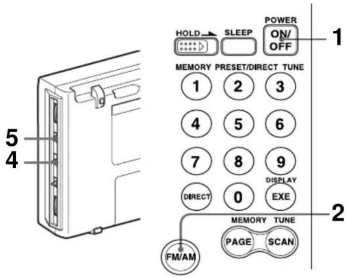
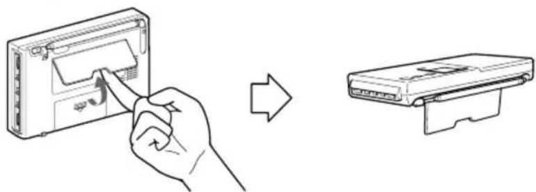
Location of parts and controls
Refer to the pages in the parentheses for details.
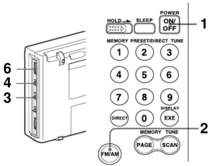
Front
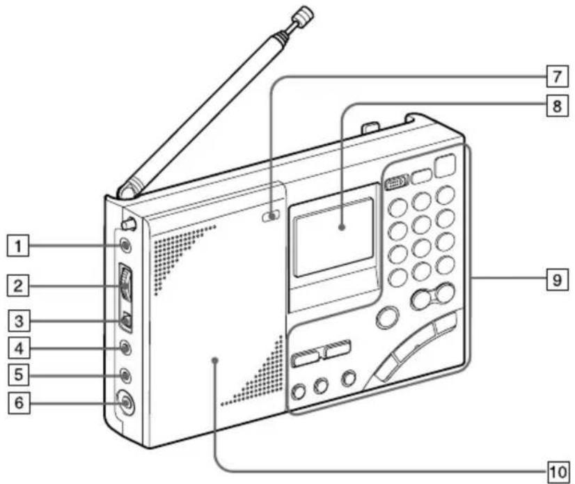
1 AM EXT ANT (AM external antenna) jack (35)
2 ATT (attenuator) control (21)
3 ATT (attenuator) ON/OFF switch (21)
4 LINE OUT (recording output) jack (33)
5 Ⓞ (headphones) jack (17, 33)
You can enjoy FM stereo broadcasting by connecting the optional stereo headphones to the unit. When using headphones, sound from the speaker will be muted.
6 DC IN 6V ◇G◆ (external power input) jack (10)
7 LIGHT button When the display is difficult to see, press this button to light up the display for approximately 10 seconds. Pressing the button again while the light is on will turn off the light. Performing button operations while the light is on will extend the lighting time.
8 Display (7)
9 Controls (6)
10 Speaker
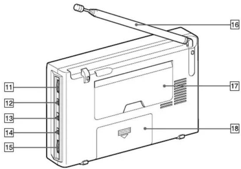
Rear
Location of parts and controls
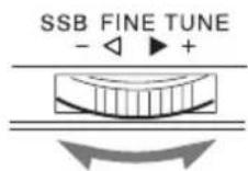
11 SSB FINE TUNE control (26)
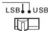
12 LSB/USB selector (26, 27)
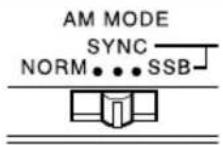
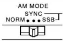
13 AM MODE selector (26, 27)
14 TONE selector (33)
15 VOLUME control
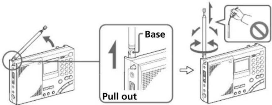
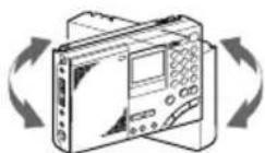
16 Telescopic antenna
Always pull out the base of the antenna before use.
Furthermore, do not use unnecessary force when storing the antenna. At this time, be sure to push in the base as well.
17 Stand

natural_image
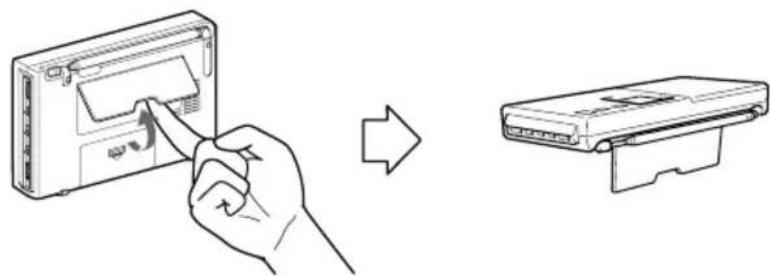
Line drawing showing a hand inserting a device into a device casing, then to insert a separate device (no text or symbols present)18 Battery compartment
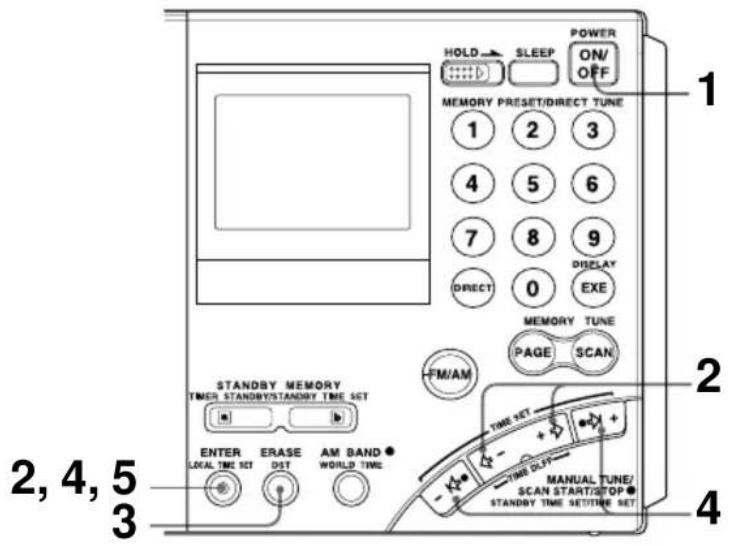
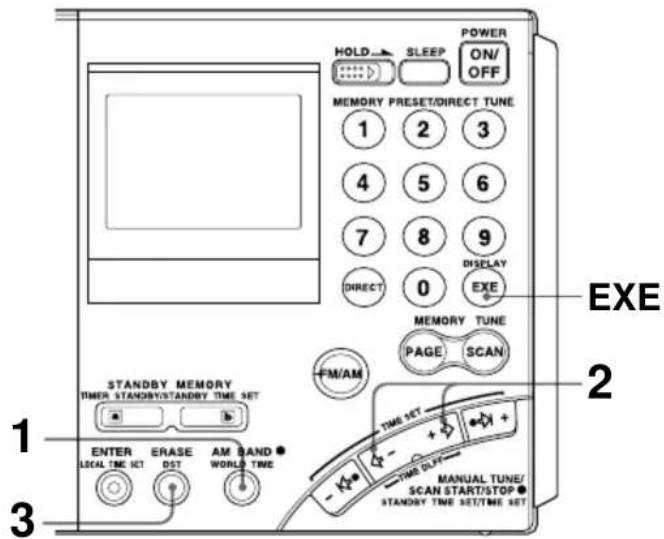
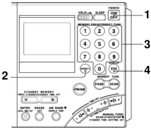
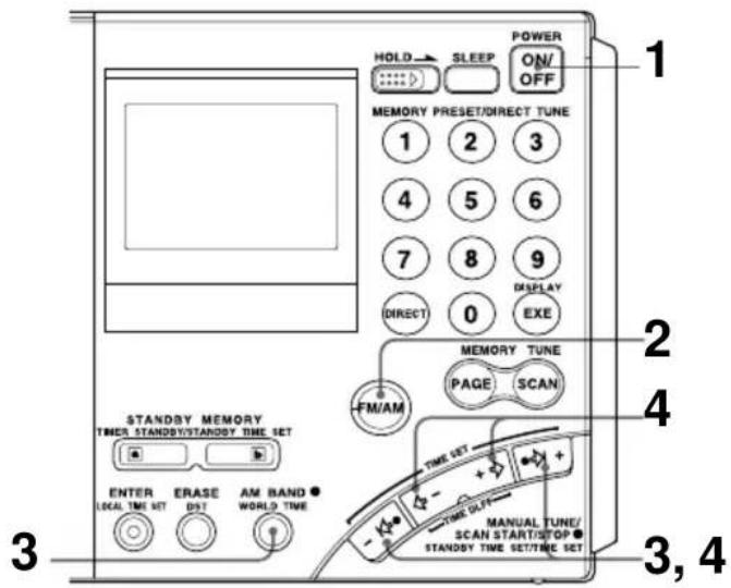
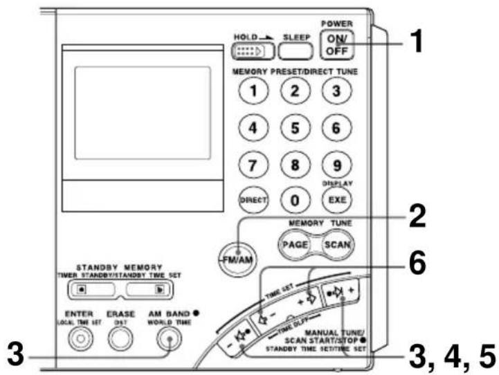
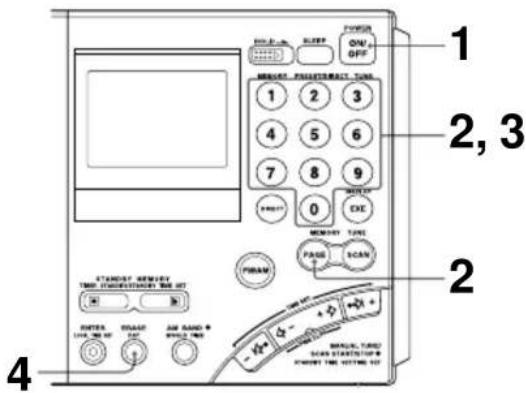
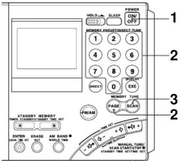
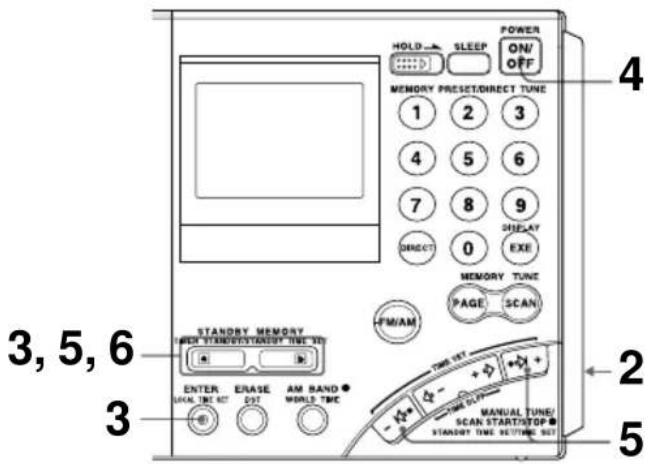
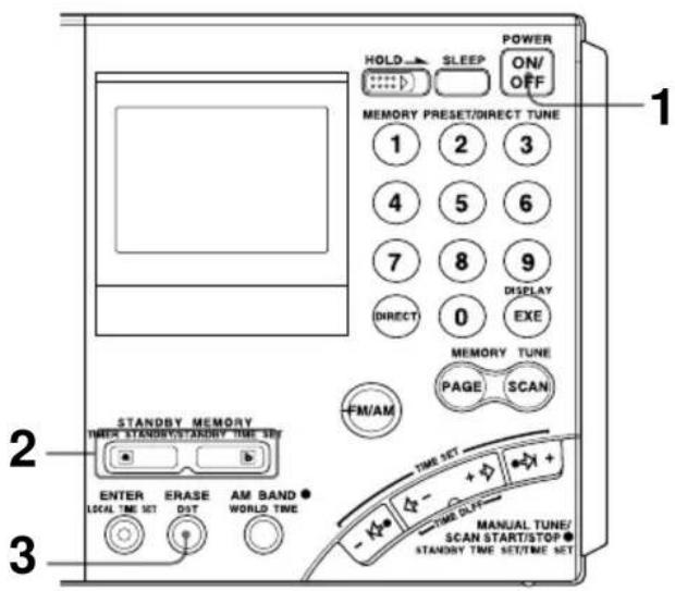
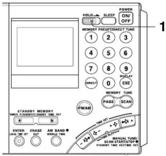
Controls

1 SLEEP button (31)
2 HOLD switch (32)
3 DIRECT button (15, 16)
4 FM/AM button (16, 18, 20)
5 STANDBY MEMORY, TIMER STANDBY/STANDBY TIME SET buttons (28, 30)
6 ENTER, LOCAL TIME SET button (11, 22, 28)
⑦ ERASE, DST (Daylight Saving Time) button (11, 13, 30)
8 AM BAND, WORLD TIME button (13, 18, 20)
9 POWER ON/OFF button
10 Number buttons (15, 16, 22, 23, 24)
11 DISPLAY, EXE button (13, 15, 16)
Press to switch to clock display while operating the radio. Press again to return to the previous display. If you do not press the button, the display will return to the previous condition in about 10 seconds.
12 SCAN button (24)
13 PAGE button (22, 24)
14 MANUAL TUNE/SCAN START/STOP, STANDBY TIME SET/TIME SET buttons (11, 13, 18, 20, 28)
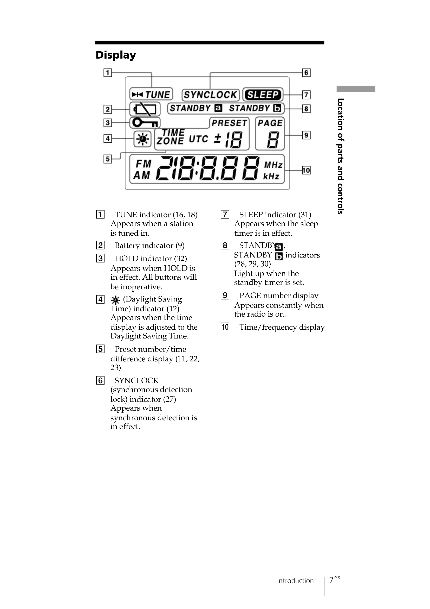
Display
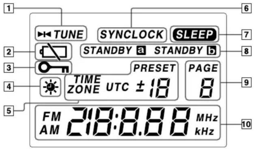
1 TUNE indicator (16, 18) Appears when a station is tuned in.
2 Battery indicator (9)
3 HOLD indicator (32) Appears when HOLD is in effect. All buttons will be inoperative.
4 (Daylight Saving Time) indicator (12) Appears when the time display is adjusted to the Daylight Saving Time.
5 Preset number/time difference display (11, 22, 23)
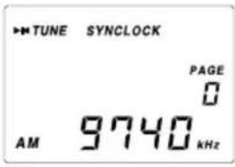
6 SYNCLOCK
(synchronous detection lock) indicator (27)
Appears when synchronous detection is in effect.
7 SLEEP indicator (31) Appears when the sleep timer is in effect.
8 STANDBY a,
STANDBY b indicators
(28, 29, 30)
Light up when the
standby timer is set.
9 PAGE number display Appears constantly when the radio is on.
10 Time/frequency display
Operating on batteries
To operate the unit on external power sources, see "Operating on AC power adaptor" (page 10).
1 Slide and open the battery compartment lid.
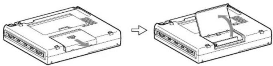
natural_image
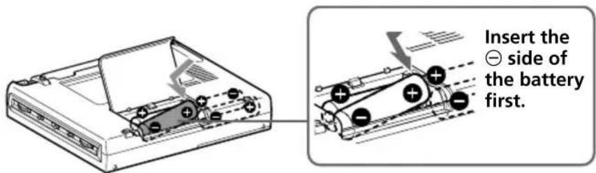
Diagram showing a device casing before and after assembly, with no visible text or symbols2 Insert four R6 (size AA) batteries in the battery compartment.
Insert with correct polarity as shown.
3 Close the battery compartment lid.
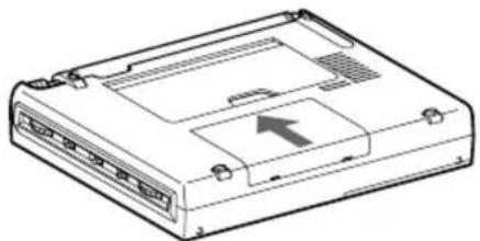
natural_image
Line drawing of a computer internal unit with ports and an arrow indicating a component (no text or symbols present)When inserting batteries for the first time, "0:00" will flash in the display. The flashing can be stopped by setting the time.
Note
It takes about 3 seconds for characters to appear in the display after inserting batteries.
Replacing the batteries
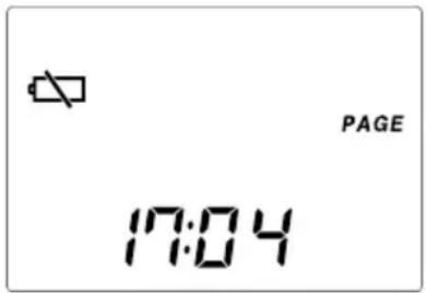
The sound will become small and distorted, and “☐” will flash in the display when the batteries become weak.
When the batteries are completely exhausted, “☐” will stop flashing (constant display), the power will turn off and all buttons will become inoperable. Replace all four batteries with new ones.
After replacing the batteries and turning on the power again, "☐" will disappear and the unit will become operable.
Note on replacing the batteries
Replace the batteries within 60 seconds while the power is turned off. Otherwise, the clock setting will be cleared. In this case, set the time again. Preset stations, the time set by standby function and the time difference between your local time and the UTC are not erased.
Battery life (JEITA*)
| Sony LR6 alkaline (size AA) Sony R6 (size AA) |
| FM approx. 47 hours approx. 15 hours |
| SW approx. 34 hours approx. 10 hours |
| MW/LW approx. 34 hours approx. 10 hours |
* Measured by JEITA (Japan Electronics and Information Technology Industries Association) standards. The actual battery life may vary depending on the circumstance of the unit.
Notes on dry batteries
Mishandling may result in leakage or damage. Be sure to follow the items below.
- Insert the batteries with correct polarity.
- Do not mix new and used batteries. Do not mix different types of batteries.
- Do not try to charge dry batteries, as they cannot be charged.
- Remove the batteries when the unit is not to be used for a long time.
- Do not carry the dry batteries with coins or other metallic objects. It can generate heat if the positive and negative terminals of the batteries are accidentally contacted by a metallic object.
Should any battery leakage occur, wipe the battery compartment thoroughly before installing new batteries.
Operating on external power sources
The unit can also be operated by connecting the AC power adaptor to the DC IN 6V (external power input) jack.
Tip
When an external power source is connected, the unit automatically switches to the external power source, regardless of whether the batteries are installed.
Notes
- Keep the batteries installed even when operating on external power sources as backup for the unit's microcomputer. Replace the batteries about once a year.
- Turn off the unit when connecting or disconnecting external power sources. Otherwise, the power may go off and “☐” may appear. In this case, turn on the power again to clear the “☐” display.
- When operating the unit on batteries, first disconnect the AC power adaptor from the wall outlet, then disconnect the AC power adaptor from the DC IN 6V jack of the unit. The unit will not operate on
batteries as long as the DC IN 6V jack is plugged in. - Use only the recommended AC power adaptor manufactured by Sony. Using AC power adaptors with different specifications (polarity of the plug, etc.) will result in malfunction and damage to the unit.
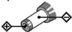
Polarity of the plug
Operating on AC power adaptor
Connect the optional AC power adaptor AC-E60HG to the DC IN 6V jack.
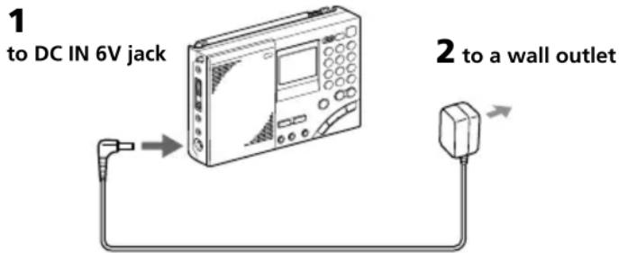
1 Connect the AC power adaptor securely to the DC IN 6V jack.
2 Connect the AC power adaptor securely to a wall outlet.
Notes
- Do not bend or twist the power cord forcibly. Do not place heavy objects on the power cord.
- Always hold the plug when disconnecting the power cord. Do not pull the cord itself.
- Disconnect the AC power adaptor from the wall outlet and radio when the unit is not to be used for a long period of time.
Setting the Current Time
"0:00" flashes in the display when installing the batteries for the first time or when the unit has been reset. Set the clock to the current time.
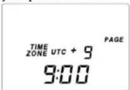
This unit can display local time, which is the time for your time zone, as well as world time, which is the time for any other area in the world. For the calculation of the time in other areas of the world, the time difference* between the local time and the UTC (Universal Time Coordinated) is used (see page 14, "Time difference with UTC for each area"). To find out the correct time, set the correct time and time difference of the area you are in.
* This unit uses time zones to pinpoint specific areas.
1 If the radio is turned on, press POWER ON/OFF to turn it off.
Note
You cannot set the clock when the radio is turned on.
2 Hold down LOCAL TIME SET and press or + to choose the time difference between your local time and the UTC.
TIME ZONE indicator will appear. Each time you press ⇔ - or
+ ⇌, the time difference (UTC + or −) and the “hour” of the clock will increase or decrease accordingly.
Two short beeps will be heard when adjusting the time difference to ±0 .
When you release LOCAL TIME SET, the
TIME ZONE indicator will disappear and the time difference with UTC will be determined.
Setting the Current time (continued)
3 To set the daylight saving time, press DST to display the ✿ indicator.
If daylight saving time is not used in your area, daylight saving time is not currently in effect, or ✦ already displayed, proceed to Step 4.
4 Hold down LOCAL TIME SET and press or I+ to set the local time.
Each time you press I or I^+ , the current time will decrease or increase by a minute. To change the digits rapidly, hold down I or I^+ .
Two short beeps will be heard when adjusting the time to "0:00".
“:” starts flashing and the clock starts running.
To switch to clock display while the radio is turned on
Press EXE. The display returns to the previous condition automatically after about 10 seconds or when EXE is pressed again. The time display period is extended when the WORLD TIME button is pressed during clock display, or when or + is pressed during world time display. During clock display, radio operations such as changing frequencies are not possible. The clock will not be displayed during auto scan (page 20) or memory scan (page 24).
For areas adopting the daylight saving time (summer time)
Press DST to display the ✿ indicator if you are now in the summer time period. When the summer time period has ended, press DST to clear the ✿ indicator. The time display will be adjusted automatically.
Tips
- The clock is displayed in the 24 hour system.
- Press LOCAL TIME SET to stop the flashing of "0:00".
- To adjust the time to the second, release LOCAL TIME SET at the time of the tone.
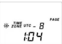
Finding out the time in other areas of the world
You can display the time for any other area in the world (WORLD time).
1 Press WORLD TIME.
If the radio is turned on, press EXE to display the clock before pressing WORLD TIME.
2 Press ⇔ -or + ⇒ to display the time difference with the UTC for the city (area) you want to see.
Two short beeps will be heard when adjusting the time difference to ±0 .
3 Press DST to display the indicator if the specified area is now under daylight saving time.
The current time of the area you want to see will be displayed.
To switch back to the LOCAL time display
Press WORLD TIME again.
Finding out the time in other areas of the world (continued)
Time difference between local time and UTC
The table shows the time difference with the UTC for each area. “+1:00” indicates one hour ahead of UTC and “-1:00” indicates one hour behind UTC.
The relationship of the UTC, LOCAL time and the time difference is as follows:
Time difference = LOCAL time* - UTC
* Local time prior to DST (daylight saving time) adjustment. The DST setting does not affect the time difference display.
Time difference with UTC for each area
| Time difference | Major city or area |
| ±0 London | |
| +1 Central Europe | Amsterdam, Stockholm, Zurich,Paris, Vienna, Brussels, Berlin, Madrid, Lisbon, Rome |
| +2 Cairo, Athens, Istanbul | |
| +3 Jeddah, Riyadh, Nairobi, Moscow | |
| +4 Dubai | |
| +5 Karachi | |
| +6 Dhaka (Dacca) | |
| +7 Bangkok, Jakarta | |
| +8 Singapore, Beijing, Hong Kong | |
| +9 Tokyo, Seoul | |
| +10 Sydney, Guam | |
| +11 Solomon, Noumea | |
| +12 Auckland, Fiji | |
| -11 Samoa | |
| -10 Hawaii, Honolulu, Tahiti | |
| -9 Anchorage | |
| -8 Los Angeles, San Francisco, Vancouver | |
| -7 Denver, Calgary | |
| -6 Chicago, Dallas, Mexico City | |
| -5 New York, Toronto, Panama, Lima | |
| -4 Caracas, Santiago | |
| -3 Rio de Janeiro, San Paulo, Buenos Aires | |
| -2 Fernando Island | |
| -1 Azores Island | |
Changing MW Channel Step
The MW channel step differs depending on the area as shown in the table below. Select the channel step according to your area.
Channel step according to area
Area Channel step
North and South American countries 10 kHz
Other countries 9 kHz
1 Press POWER ON/OFF to turn off the radio.
2 Press DIRECT.
Perform Step 3 within 10 seconds. Otherwise, the unit will return to the condition prior to Step 2. In this case, repeat from Step 2. In addition, perform steps after Step 3 within 10 seconds as well.
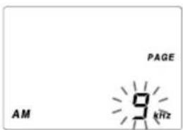
3 Enter the channel step using the number buttons.
To enter 9 kHz, press 9 and to enter 10 kHz, press 1 and 0.
4 Press EXE to finish operation.
The entered channel step will flash for about 3 seconds and the unit will return to the clock display.
Two short beeps will be heard when entering numbers other than "9" and "10". In this case, repeat from Step 2 after returning to the clock display.
Directly entering the frequency
— Direct tuning
If you know the frequency of the station you want to listen to, you can use the number buttons for quick and accurate tuning.
1 Press POWER ON/OFF to turn on the radio.
2 Press FM/AM to select either band.
To listen to SW (short wave), MW (medium wave) or LW (long wave) broadcasts, select AM.
3 Press DIRECT.
The frequency disappears from the display. Perform Step 4 within 10 seconds.
Otherwise, the unit will return to the condition prior to Step 3. In this case, repeat from Step 3. In addition, perform steps after Step 4 within 10 seconds as well.
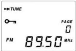
4 Press the number buttons and input the frequency of the desired station.
FM band: You can ignore the decimal point.
Example: To enter 89.5 MHz, press 8, 9 and 5.
AM band: You can ignore the last 3 digits if they are all zero.
Examples: To enter 810 kHz, press 8, 1 and 0.
To enter 10 000 kHz, enter 1 and 0.
To enter 12 095 kHz, enter 1, 2, 0, 9 and 5.
The minimum frequency step for direct input is 0.05 MHz (50 kHz) for FM and 1 kHz for AM.
5 Press EXE.
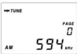
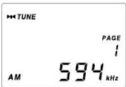
The unit will tune in to the entered frequency. "▶◀ TUNE" will appear in the display when the station is tuned in.
To correct input
Press DIRECT and repeat from Step 3.
If you enter an invalid frequency
You will hear two short beeps and the display will return to the frequency you are currently listening. Check the frequency and repeat from Step 3.
To turn off the radio
Press POWER ON/OFF.
Tips
- You can use the optional stereo headphones to enjoy FM stereo broadcasts.
- When listening to news broadcasts, set the TONE selector to NEWS for voice enhancement. When listening to music, set the selector to MUSIC.
- Reception of frequencies around 3.64 MHz may be difficult due to internal spurious signals generated by the built-in oscillators.
To improve reception
FM reception
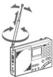
Extend the telescopic antenna, and adjust the direction and angle.
(See "telescopic antenna", page 5)
natural_image
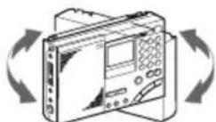
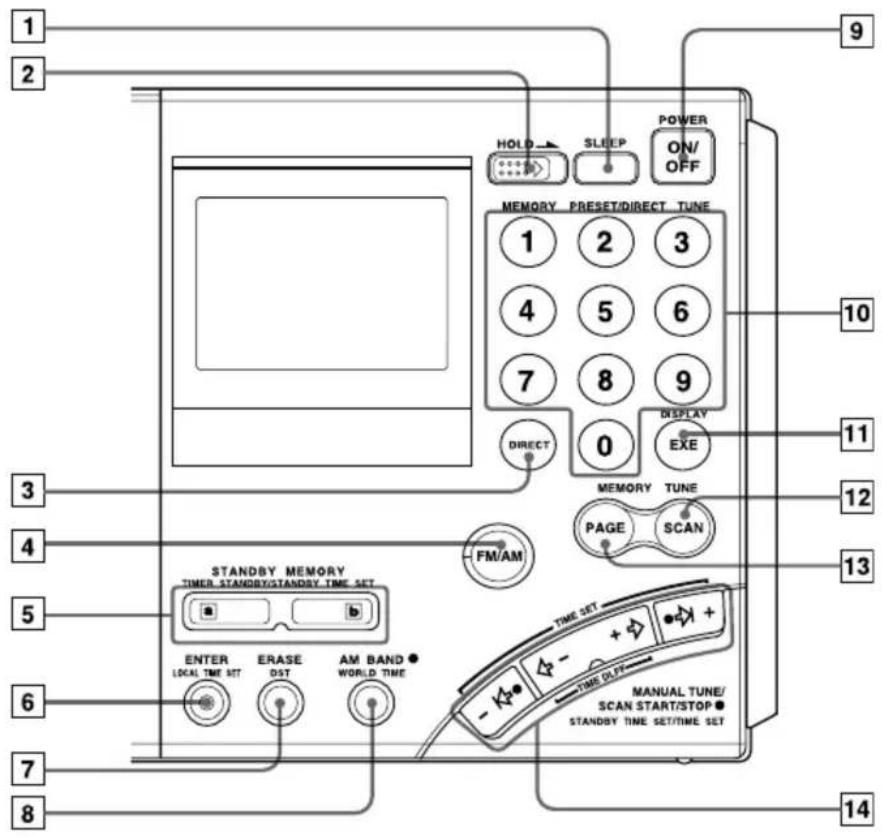
Illustration of a radio device with a pointer and circular arrows indicating signal or rotation (no text or symbols)MW/LW reception
Retract the telescopic antenna and rotate the unit to reorient the built-in ferrite bar antenna.
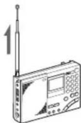
SW reception
Fully extend the telescopic antenna vertically. For SW reception, you can enjoy even better reception by using the supplied external antenna (page 34)
natural_image
Line drawing of a radio device with antenna and control panel (no text or symbols)When there is interference
Turn the ATT switch on the side of the unit to ON, and adjust the ATT control (page 21).
Bad reception
Connect the optional external antenna (page 35).
Manually selecting the frequency
— Manual tuning
Use ,+or-,+ to change the frequency.
1 Press POWER ON/OFF to turn on the radio.
2 Press FM/AM to select either band.
To listen to SW, MW or LW broadcasts, select AM.
3 For AM bands, hold down AM BAND and press -I or I+ to select MW (medium wave), LW (long wave) or meter band (short wave).
The lowest frequency of the band (meter band) will appear in the display each time the button is pressed.
For FM, skip this step.
4 Press -I , I+ or -, + repeatedly to tune in to the desired station.
The frequency changes in the channel steps shown below each time the button is pressed, and the “▶◀ TUNE” appears when a station is tuned in.
| Band When outer is pressed is pressed | -I↔ or ⇌ I+ | When inner ⇌ -or +→ |
| FM 0.05 MHz 0.05 MHz | ||
| SW 5 kHz 1 kHz | ||
| MW 9 kHz or 10 kHz 1 kHz | ||
| LW 9 kHz 1 kHz | ||
Tips
- The unit will perform auto scan when -I or I+ is held down (see "Searching the station automatically - Auto scan tuning", page 20).
- The frequency changes rapidly when - or + is held down and stops when the button is released. In the AM bands (MW, SW and LW), the unit scans continuously in the range of 150 to 29 999 kHz.
What is a meter band?
Meter bands refer to frequency bands which short wave broadcasts are divided into wavelengths. Normally, international broadcast frequencies are assigned. With this unit, there are 14 meter bands.
Frequency range of bands/meter bands
Unit: kHz for AM, MHz for FM
| Band | Frequency Range | Scan Frequency Range | Meter band | |
| AM | LW | 150–529 153–522 — | ||
| MW | 530–1 620 | 530–1 620 * — | ||
| 531–1 620 ** — | ||||
| SW 1 | 621–29 999 | 2 250–2 550 120 meter band | ||
| 3 150–3 450 90 meter band | ||||
| 3 850–4 050 75 meter band | ||||
| 4 700–5 100 60 meter band | ||||
| 5 900–6 250 49 meter band | ||||
| 7 100–7 400 41 meter band | ||||
| 9 400–10 000 31 meter band | ||||
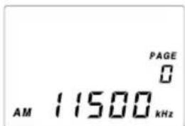
| 11 500–12 150 25 meter band | ||||
| 13 500–13 900 22 meter band | ||||
| 15 000–15 900 19 meter band | ||||
| 17 450–18 000 16 meter band | ||||
| 18 850–19 100 15 meter band | ||||
| 21 450–21 950 13 meter band | ||||
| 25 600–26 100 11 meter band | ||||
| FM | 76.00–108.00 76.00–108.00 — | |||
* 10 kHz channel step (see page 15).
** 9 kHz channel step (see page 15).
Note
The actual frequency range of short wave broadcasts and the range of the meter bands for this unit may differ. Refer to the supplied "Wave Handbook" for more information.
Searching the station automatically
— Auto scan tuning
1 Press POWER ON/OFF to turn on the radio.
2 Press FM/AM to select either band.
To listen to SW, MW or LW broadcasts, select AM.
3 For AM bands, hold down AM BAND and press I or I+ to select MW (medium wave), LW (long wave) or meter band (short wave).
The lowest frequency of the band (meter band) will appear in the display each time the button is pressed.
For FM, skip this step.
4 Hold down I or I+ for about 2 seconds. Release when the unit starts scanning.
Stations will be searched automatically. The unit will stop at each reception and will resume scanning after about 3 seconds (auto scan tuning).
The unit will scan within the frequency range of the chosen band or meter band (see "Frequency range of bands/meter bands", page 19).
5 When the unit tunes in to the desired broadcast, press the outer -I ⇔ or I+.
Auto scan will stop at that broadcast station.
6 Press the inner - or + to adjust to the optimum frequency.
Tips
- The unit scans the frequencies in descending order when holding down I , and in ascending order when holding down I^+ .
- To change the scanning direction, hold down either -I or I+ opposite to the current direction for 3 seconds. This is convenient when you want to return to the previous reception after the unit has resumed scanning.
To adjust the reception sensitivity for scanning
— Using the ATT switch and ATT control
When scanning for MW broadcasts at night when reception is intense or when scanning under prevalent interference, the unit may stop scanning to null broadcasts frequently.
If the unit stops scanning frequently, adjust the reception sensitivity.
Under normal conditions, set the ATT switch to OFF (maximum reception sensitivity).
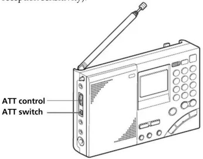
1 Set the ATT switch to ON.
The ATT control is enabled.
2 Turn the ATT control and adjust the reception sensitivity.
Turn the ATT control toward MAX to reduce sensitivity. The unit will skip weaker signals and stop at only stronger ones.
Note
If the ATT control is turned too much toward MAX, the unit will not stop at any weaker signals at all. Set the ATT switch to OFF if you do not need to use the attenuator.
Presetting stations
— Preset tuning
There are a total of 10 pages available for presets (page 0 to page 9) and you can preset up to 10 stations per page for a maximum of 100 preset stations. By presetting, you can tune in to stations simply by using the number buttons (0 to 9).
Convenient way using preset tuning
For short wave (SW) broadcasts, frequencies available for reception differ depending on the time and period even for the same station. Presetting different frequencies for the same station on a page will allow you to tune in to that station easily by using the memory scan tuning (page 24).
(For frequencies of each station, see the supplied Wave Handbook.)
Presetting and changing the stations
Frequencies may already be preset in the memory at the time of purchase. In this case, erase or change the unnecessary stations.
1 Press POWER ON/OFF to turn on the radio.
2 Tune in to the station you want to preset.
For details concerning tuning, see Direct tuning (page 16), Manual tuning (page 18) or Auto scan tuning (page 20).
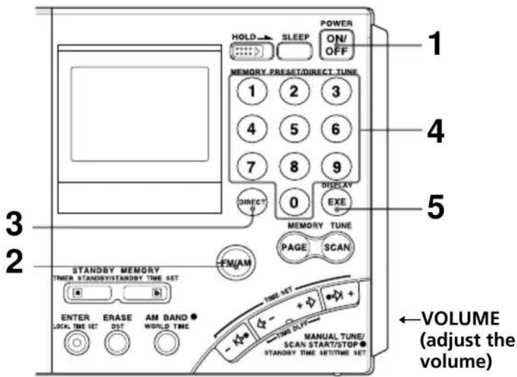
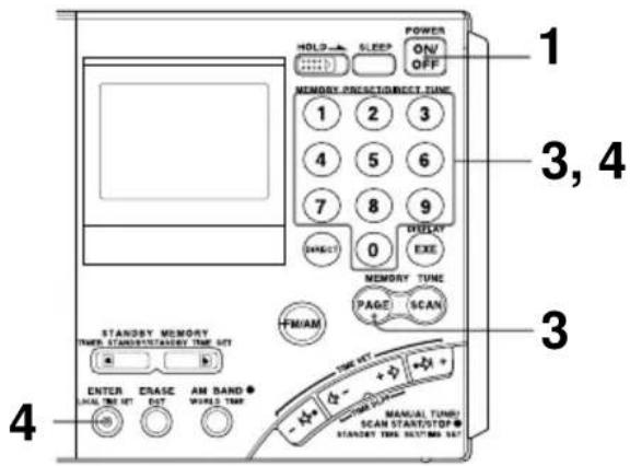
3 Press PAGE and press a number button between 0 and 9 to select a page number.
The number will change from a flashing display to a constant display and the page number will be determined.
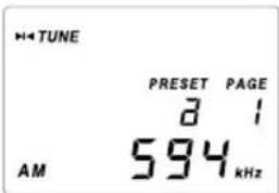
4 Hold down ENTER and press a number button between 0 and 9 to select a preset number.
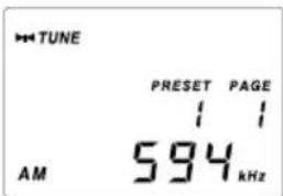
Two short beeps will be heard and the PRESET indicator will change from a flashing display to a constant display. The frequency will be stored in the selected preset number.
The example shows AM 594 kHz is stored in preset number 1 of page number 1.
Note
If a station has already been stored to the button you chose, it will be overwritten by the new preset.
Tuning in to a preset station
1 Press POWER ON/OFF to turn on the radio.
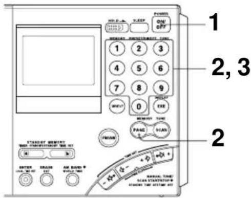
2 Press PAGE and press the page number (0 to 9) where the desired preset station is stored.
3 Press the number button (0 to 9) of the desired preset station.
The radio will tune in to the station assigned to the button.
If no station is preset
Two short beeps are sounded when the button is pressed (0 to 9) and after “- - - -” is displayed momentarily, the unit will return to the previous display.
Erasing a preset station
1 Press POWER ON/OFF to turn on the radio.
2 Press PAGE and press the page number (0 to 9) where the desired station to erase is stored.
3 Press the number button (0 to 9) of the desired station to erase.
4 Hold down ERASE.
The preset number flashes while you hold down ERASE.
Two short beeps sound after about 3 seconds and the stored station is erased. The preset number display will disappear.
Searching available stations from presets
— Memory scan tuning
You can scan stations stored on a page.
Convenient way using memory scan tuning
When performing memory scan tuning, scanning will stop at the available stations. By storing frequencies of a short wave (SW) broadcast station that differ depending on the time and period on a page, the available frequency can be received by scanning that page.
1 Press POWER ON/OFF to turn on the radio.
2 Press PAGE and press the number button (0 to 9) of the page to scan.
3 Press SCAN.
The unit will scan all stations preset to the selected page in ascending order and stop when there is reception. Press SCAN again to select the next station. After the highest preset number has been scanned, the unit will return to the smallest preset number and scan again.
To stop memory scan during operation
Press SCAN while memory scan is in operation.
When there are no stations available
If no stations are received after scanning, the unit will return to the preset number where the scan was started and two short beeps will be heard.
When you press SCAN for a page with no presets
Two short beeps sound, “----” is displayed and the unit will return to the previous state.
Tips
- Scanning works faster if you preset frequencies in descending or ascending order in preset number orders.
- When scanning at night when reception is intense or when scanning under prevalent interference, the unit may stop scanning to null broadcasts frequently. In this case, set the ATT switch to ON, and adjust the ATT control (see “To adjust the reception sensitivity for scanning”, page 21). Under normal conditions, set the ATT switch to OFF.
Note
Many international broadcasts for short wave have limited broadcast hours. Due to this, the unit may not be able to tune in to the station outside the broadcast hours, or the unit may tune in to another station such as the local station of your area, etc.
Receiving SSB and CW transmissions
You can receive SSB (Single Side Band) and CW (Continuous Wave) transmissions with this unit.
1 Press POWER ON/OFF to turn on the radio.
2 Press FM/AM to select AM.
3 Set the AM MODE selector to SSB.
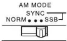
4 Set the LSB/USB selector to either LSB or USB.
To receive CW transmission, select LSB.
5 Adjust the frequency.
For tuning, see Direct tuning (page 16), Manual tuning (page 18), or Auto scan tuning (page 20).
6 Use SSB FINE TUNE control to fine tune in to a frequency where you have the best reception.
You can fine tune the received frequency in a range of about ±1.5 kHz. During this time, the frequency display will not change.
Tip
For more information on SSB and CW, refer to "Tips on radio waves", page 41.
Adjusting for optimum AM reception
— Synchronous detection
With synchronous detection, you can adjust AM reception (especially SW reception) to optimum conditions.
1 Press POWER ON/OFF to turn on the radio.
2 Press FM/AM to select AM.
3 Adjust the frequency.
For tuning, see Direct tuning (page 16), Manual tuning (page 18), Auto scan tuning (page 20), or Memory scan tuning (page 24).
4 Set the AM MODE selector to SYNC.
5 Set the LSB/USB selector to either LSB or USB, whichever has the best reception.
SYNCLOCK indicator will appear when the synchronous detection circuit is locked.
Tip
For more information on synchronous detection, see "Tips on radio waves", page 41.
Note
SYNCLOCK indicator may not appear when the received signal is weak and synchronous detection does not take effect.
Waking up to the radio or alarm — Standby function
Waking up to the radio
You can wake up to your favorite radio program using the standby function. You can preset different frequencies and standby times to STANDBY MEMORY a and b
To wake up to the alarm, see "Waking up to the alarm", page 30.
Make sure the clock is set correctly before using the standby function (page 11).
The standby timer takes effect when the set time and the displayed time match. You do not need to take into consideration the LOCAL time and WORLD time. If you want to wake up at 8:00, set 8:00. After setting the standby time, simply select the displayed time to LOCAL time or the time of the desired area you want to use (WORLD time), and the standby function will operate at 8:00 am for the specified area.
1 Tune in to the station you want to listen.
For tuning, see the various tuning methods (pages 16–27).
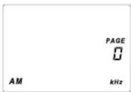
2 Adjust the volume using the VOLUME control.
3 Hold down ENTER and press STANDBY MEMORY or b
When ENTER is held down, the PRESET indicator will flash. Two short beeps sound when STANDBY MEMORY is pressed and the selected station will be stored to the standby memory button. The standby memory number of "a" or "b" will appear in the display.

4 Press POWER ON/OFF to turn off the radio.
Note
Always turn off the power when setting the standby time. The time cannot be set when the radio is on.
5
Hold down STANDBY MEMORY a or b selected in Step 3 and press -l ⇔ or ⇔ l+ repeatedly to set the standby time.
The time changes by a minute each time -I or I+ is pressed. Hold down the button to rapidly change the digits.
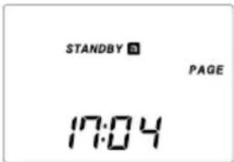
When a is held down, STANDBY or SANDBY will flash in the display.
6
Release STANDBY MEMORY of a
"STANDBY a or "STANDBY " lights up and the standby setting is complete. The clock indication returns to the current time.
b
7
Display the time of the area you want the standby function to take effect (LOCAL time or WORLD time).
When the time is reached and the standby function activates
The radio turns on, SLEEP indicator appears and the preset station is received. The power will automatically turn off after about 60 minutes.
To check the standby time
Hold down STANDBY MEMORY a or b with the radio turned off. The preset standby time is displayed while the button is pressed.
To change the standby time
Perform Step 4 and after and set the new time.
To cancel the standby function
Press STANDBY MEMORY a or b with the radio turned off so that STANDBY a or STANDBY b is cleared from the display. At this time, release button ar within a second. Otherwise, the unit goes to Step 5 for setting the standby time again.
Tips
- To temporarily cancel the standby function, turn off the radio and slide HOLD in the direction of the arrow so that “○—” is displayed. The timer goes back to effect when “○—” is cleared from the display (see “Preventing operation errors – Hold function”, page 32).
- Once the standby presets are set, the radio turns on at the preset time everyday unless the standby function is canceled by clearing STANDBY a r STANDBY . Even when the standby function is canceled, the station and time stored in STANDBY MEMORY a r b are not erased until new settings are overwritten.
- If the standby memory is in standby status, it takes effect even when you are listening to the radio. The radio switches to the preset standby frequency at the standby time.
- You can set both STANDBY and to be standby status at the same time. The radio turns on at the first standby time to receive the first standby frequency, then switches to the second standby frequency at the second standby time.
- If both STANDBY and are set to the same standby time, only STANDBY will operate.
Waking up to the radio or alarm — Standby function (continued)
Waking up to the alarm
If STANDBY MEMORY ☐ without a frequency preset is activated, the alarm sounds at the standby time. Erase if a frequency is preset.
1 Press POWER ON/OFF to turn on the radio.
2 Press STANDBY MEMORY or a b
The preset station is received.
If no frequency is stored, two short beeps sound, “----” appears in the display and the unit will return to the previous condition.
Proceed to Step 4.
3 Hold down ERASE.
The preset number display flashes while ERASE is held down.
Two short beeps sound after about 3 seconds and the stored station is erased. The "a" or "b" indicator will be cleared from the display.
4 Follow Step 4 and after of "Waking up to the radio", page 28 to set the standby time.
The alarm sounds at the standby time and stops after about 3 minutes.
To stop the alarm
Press any button on the front.
Notes
- The alarm volume cannot be adjusted with the VOLUME control.
- If the standby time is reached when listening to the radio, the radio is turned off and switched to the clock display, and the alarm is sounded.
Falling asleep listening to the radio
— Sleep timer function
You can go to sleep while listening to the radio. The radio will automatically turn off after the set time (60 minutes, 45 minutes, 30 minutes or 15 minutes) has passed.
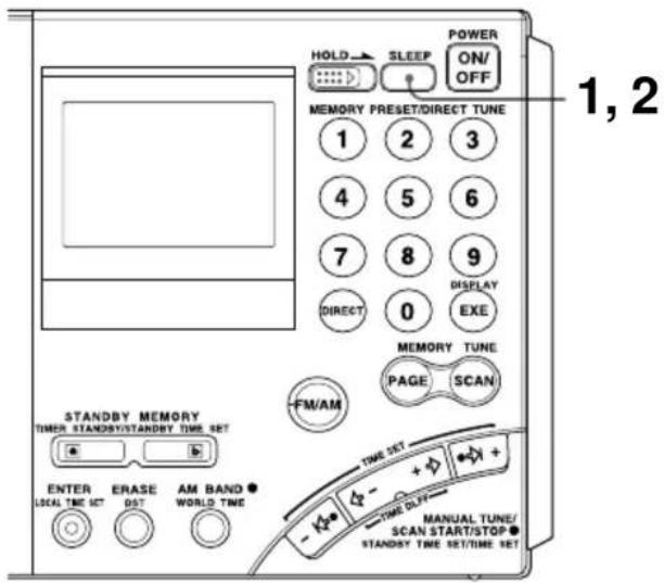
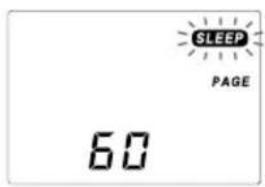
1 Press SLEEP.
"60" for the activation time of the sleep timer appears and "SLEEP" flashes. If the radio is off when pressing SLEEP, the radio will turn on.
2 Press SLEEP repeatedly until the desired time is displayed while "SLEEP" is flashing.
The display changes as shown below each time the button is pressed.
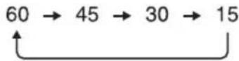
Two short beeps sound when returning to 60. The SLEEP indicator will change to a constant display about 3 seconds after the time has been set. The activation time display will change to the frequency display and the sleep timer will start.
3 Select the station you want to listen to and adjust the volume.
When the set time passes, the radio will automatically turn off.
To turn off the radio before the sleep timer setting is reached Press POWER ON/OFF.
To extend the activation time of the sleep timer
Press SLEEP again and set the time.
Preventing operation errors — Hold function
When the hold function is activated, all buttons become inoperative, preventing accidental operation when the radio is being carried or used. The hold function can also be used to temporarily cancel the standby timer function.
1 Slide HOLD switch in the direction of the arrow.
“○—” indicator will appear and all buttons become inoperative.
To cancel the hold function
Slide HOLD switch in the direction opposite the arrow so that "o-n" disappears from the display.
Tips
When the hold function is activated while the radio is turned off, the standby timer function is temporarily canceled (see "Waking up to the radio or alarm – Standby function", page 28). The standby timer can only be temporarily canceled when the radio is off.
Recording broadcasts
You can record radio broadcasts by connecting the radio to a cassette recorder with a connecting cable.
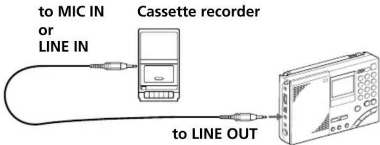
1 Connect the radio to a cassette recorder with the optional connecting cable.
Use the appropriate cable for the type of cassette recorder.
| Cassette recorder | Connecting cable (optional) | |
| Type Jack | ||
| Monaural MIC | IN (minijack) RK-G135 | |
| Stereo | MIC IN (minijack) RK- | G134 |
| LINE IN (minijack) RK- | G136 | |
| LINE IN (pinjack) RK- | G129 | |
2 Tune in to the station you want to record.
Set the TONE selector to NEWS or MUSIC as necessary.
3 Record on the cassette recorder.
When recording on a stereo cassette recorder
Both channels will be recorded in monaural. To record FM broadcasts in stereo, be sure to insert headphones into the jack. Otherwise, both channels will be recorded in monaural.
Tip
Adjusting the VOLUME control on the radio has no effect on the recording.
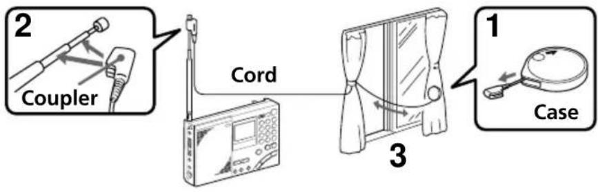
Using the supplied SW external antenna
Although you can normally enjoy SW (short wave) broadcasts with the telescopic antenna, use the supplied SW antenna when the reception is bad such as when inside a steel building, etc., or when you want more stable reception.
flowchart
graph TD
    A["1 Coupler"] --> B["3 Cord"]
    B --> C["Case"]
1 Completely pull out the cord from the case.
2 Mount the coupler on the telescopic antenna.
3 Place the antenna cord.
If the window can be opened: Check for any danger and place the cord outside the window along with the case.
If the window cannot be opened: Extend the cord fully to the width of the window.
Note
When placing the compact antenna outside, make sure it causes no inconvenience to others. In addition, securely fix the antenna so that it does not drop.
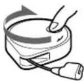
After using
Turn the reel in the direction of the arrow to retract the cord.
Using the optional external antennas
For better reception of SW (short wave), MW (medium wave) and LW (long wave) broadcasts, use the optional wide range antenna AN-1, AN-102 or SW active antenna AN-LP1.
Installation
- Do not place the radio or antenna near fluorescent lighting, televisions, telephones, computers, etc., as this may cause noises to be heard.
• Install the external antenna as far away as possible from roads. - For details concerning the external antenna, see the instruction manual supplied with the antenna.
- When using the external antenna, make sure that the telescopic antenna is fully retracted.
Notes
- Since it is necessary to select the frequency using the antenna controller for SW active antenna AN-LP1, you may not obtain the best performance when operating the memory scan function of the radio with AN-LP1 connected.
- Do not connect external antennas other than those recommended to the AM EXT ANT jack. This jack outputs DC voltage for antenna power supply.
- Never touch the wire of the external antenna during a thunderstorm. Furthermore, immediately disconnect the AC power adaptor from the radio when operating on house current.
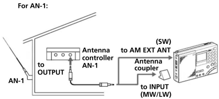
Tuning in with AN-1/AN-102
When tuning in to SW broadcasts
Connect the antenna controller output jack and the AM EXT ANT (AM external antenna input) jack of the unit with the connecting cord (supplied with AN-1/AN-102).
When tuning in to MW/LW broadcasts
1 Connect the OUTPUT jack of the antenna controller and the INPUT jack of the antenna coupler with the connecting cord (connecting cord and antenna coupler is supplied with AN-1/AN-102).
2 Place the antenna coupler near the radio and where there is good reception.
Retract the telescopic antenna of the radio.
flowchart
graph TD
    A["AN-1"] -->|to OUTPUT| B["Antenna controller AN-1"]
    B --> C["Antenna coupler"]
    C --> D["(SW) to AM EXT ANT"]
    D --> E["to INPUT (MW/LW)"]
Precautions and maintenance
On placement
- Do not leave the unit near heat sources, such as radiators or air ducts, or in a place subject to direct sunlight, excessive dust, humidity, rain, mechanical vibration or shock.
- Use the unit within a temperature range of 0^ to 40^ (32°F to 104^ ). If it is used in temperatures outside this range, an irregular display (i.e., 88.88) may appear. If it is used in temperatures below this range, the display may change very slowly. The unit will return to its normal condition when the unit is used in its recommended temperature range once again.
- Reception may be difficult or noisy in vehicles or buildings. Try listening near a window.
On safety
- Operate the unit only on 6 V DC with four R6 (size AA) batteries.
For AC operation, use the optional AC power adaptor recommended for this unit. Do not use any other type of AC power adaptor.
- The unit is not disconnected from the AC power source (mains) as long as it is connected to the wall outlet, even if the unit itself has been turned off.
- Disconnect the AC power adaptor from the wall outlet when the unit is not to be used for a long period of time.
- The name plate indicating operating voltage, etc., is located at the rear of the unit.
- Should any solid object or liquid fall into the unit, unplug the unit, and have it checked by qualified personnel before operating it any further. Make sure that no liquid or foreign material enters the DC IN 6V jack of the unit. This may lead to malfunction of the unit.
- When the casing becomes soiled, clean it with a soft dry cloth dampened with mild detergent solution. Never use abrasive cleansers or chemical solvents, as they may mar the casing.
- Since a strong magnet is used for the speaker, keep personal credit cards using magnetic coding or spring-wound watches away from the unit to prevent them from possible damage caused by the magnet.
- If there is lightning and when using the external antenna, disconnect the AC power adaptor immediately from the wall outlet, if connected. Never touch the antenna wire when there is a lightning storm.
- Never connect a ground wire to a gas pipe.
- Do not drop or apply excessive force to the unit. Malfunction may occur as a result.
Service and repair
When taking your unit for service or repair, take note of important preset settings. They may be deleted depending on the type of necessary repair.
If you have any questions or problems concerning your unit, please consult your nearest Sony dealer.
Troubleshooting
If you have any trouble with the unit, read the instruction manual once more and check the following before requesting for repair.
| Symptom | Cause and remedies |
| The radio does not accept button operations. | The HOLD function is activated.→Slide HOLD switch in the direction opposite the arrow (to disappear “○—”) (page 32) |
| The power does not turn on when POWER ON/OFF is pressed. | Improper installation of batteries. Weak batteries.→Insert the batteries with correct polarity. Replace with new batteries.The AC power adaptor is disconnected.→Properly connect the AC power adaptor. |
| The display is not operating. | Improper installation of batteries.→Insert the batteries with correct polarity. |
| The display is dim. | Weak batteries.→Replace with new batteries. |
| The display is slow. | The unit is being used in extremely low temperature or in high humidity.→Use the unit under appropriate conditions. |
| There is no sound output. | The volume is turned down completely.→Adjust the volume.The headphones are plugged in.→Unplug the headphones.Improper installation of batteries.→Insert the batteries with correct polarity. |
| There is noise, bad reception or weak sensitivity. | Weak batteries.→Replace with new batteries.Improper tuning or antenna adjustment.→Adjust tuning and antenna properly.Weak radio signal.→Listen to the radio near a window when in a vehicle or building.ATT switch is set to ON.→Set ATT switch to OFF (page 21). |
| Cannot complete direct tuning. | You took more than 10 seconds between button operations.→Complete each button operation within 10 seconds. |
| Cannot preset a station. | Incorrect procedure.→Hold down ENTER and press a number button (0–9) (page 22). |
| Cannot recall a preset station. | You pressed an incorrect number button for the desired station.→Press the correct number.The preset setting was accidentally erased.→Preset the station again (page 22). |
| The radio does not turn on at the standby time. | You forgot to press STANDBY MEMORYar .b→ Press STANDBY MEMORYar (page 29).The HOLD function is activated.→ Slide HOLD switch in the direction opposite the arrow (to disappear “○—n”) (page 32).You took more than 60 seconds to replace the batteries.→ Set the correct time.The volume is turned down completely.→ Adjust the volume.No frequencies are stored in the STANDBY MEMORY.→ Store a frequency in the STANDBY MEMORY (page 28). |
| Cannot perform memory scan. | There are not station presets in the page to scan, or there is only one preset.→ Preset 2 or more stations in the page to scan. |
| Auto scan will not stop. | ATT switch is set to ON.→ Set ATT switch to OFF, or adjust the ATT control. |
Specifications
Circuit system FM: Super heterodyne
AM: Dual conversion super heterodyne
Frequency range FM: 76–108 MHz
SW: 1 621–29 999 kHz
MW: 530–1 620 kHz
LW: 150–529 kHz
Output LINE OUT jack (stereo minijack) · 1
Recording output level approx. 245 mV, output impedance less than 10 kΩ
(headphones) jack (stereo minijack) · 1 16 Ω
Speaker Approx. 77 mm diameter, 8 Ω · 1
Maximum output 380 mW (at 10 % harmonic distortion)
Power requirements DC 6 V, four R6 (size AA) batteries
External power source DC IN 6V
Dimensions Approx. 190 · 118.8 · 35.3 mm incl. projecting parts (w/h/d)
Mass Approx. 536 g Approx. 608 g (incl. four R6 (size AA) batteries)
Supplied accessories
Carrying case (1)
Compact antenna AN-71 (1)
Wave Handbook (1)
Optional accessories
LW/MW/SW wide range antenna AN-1, AN-102
SW active antenna AN-LP1
AC power adopter AC-E60HG
Connecting cable RK-G135 (Stereo miniplug ↔ miniplug)
RK-G134 (Stereo miniplug ↔ stereo miniplug)
RK-G136 (Stereo miniplug ↔ stereo miniplug)
RK-G129 (Stereo miniplug pin plug·2)
The AC power adopter's operating voltage varies depending upon the country in which it is sold. Buy the AC power adopter in the country you intend to use it.
Your dealer may not handle some of the above listed optional accessories. Please ask your dealer for detailed information on the optional accessories available in your country.
Design and specifications are subject to change without notice.
Tips on radio waves
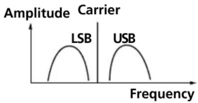
What is SSB (Single Side Band)?
SSB is very popular among ham and business radio transmissions, and is commonly used in many amateur bands because of its superiority in signal intelligibility. Its impressive signal intelligibility is achieved with minimum interferences when compared to DSB (Double Side Band) owing to its half bandwidth structure.
In general, SSB transmissions employ the USB (Upper Side Band) modulation, while amateur band transmissions below 10 MHz employ the LSB (Lower Side Band) modulation.
Conventional radios without a BFO (Beat Frequency Oscillator) circuit cannot receive SSB transmissions successfully. This unit can receive SSB transmissions successfully with the built-in BFO (Beat Frequency Oscillator) circuit.
line
| Carrier | Frequency | | ------- | --------- | | LSB | Low | | USB | High |What is CW (Continuous Wave)?
CW is also popular among ham and business radio transmissions. Unlike other signals, the amplitude of a carrier is not modulated for CW transmissions. CW transmissions convey information by interrupting the carrier and use Morse code as a means of communication.
This unit can receive CW transmissions successfully with the built-in BFO (Beat Frequency Oscillator) circuit as beat sound only. To fully comprehend the information transmitted by CW transmissions, an understanding of the Morse code is prerequisite.
What is synchronous detection?
There are two underlying obstacles in optimum AM reception: distortions due to fading and interferences from adjacent broadcast stations.
Synchronous detection is effective in solving these obstacles.
Distortions due to fading are generally caused by over-modulation which occurs when a carrier component of the received signal is attenuated along the way. The synchronous detection circuit of this unit generates a pure carrier frequency with no level variation which is ideally synchronized with the original carrier to compensate for the attenuated carrier component, thus dramatically reducing distortion.
Likewise, AM (LW, MW, and SW) broadcast generally employs DSB (Double Side Band) signals for transmissions in which the modulated signals are transmitted using both the upper and lower side bands (USB and LSB). In most cases, one of the side bands is affected by interferences from adjacent broadcast stations (i.e., beats). The synchronous detection circuit of this unit extracts one of the two sides (USB or LSB) of the DSB
(Double Side Band) signal which is free from interferences. This allows clear reception without the interferences from adjacent broadcast stations.
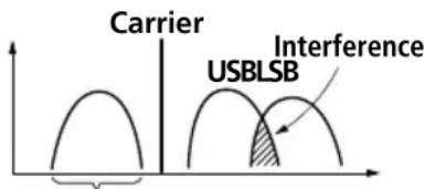
Only this side is received.
Avertissement
— Accord direct.... 16
Nomenciaure
17 Support
natural_image
Illustration showing a hand inserting a device into a device panel, then adding a separate card to a folder (no text or symbols present)natural_image
Diagram showing a device casing before and after assembly, with no visible text or symbolsnatural_image
Line drawing of a computer internal component with ports and an arrow indicating a specific area (no text or symbols present)natural_image
Illustration of a radio device with a rotating pointer and signal waves (no text or symbols)Réception MW/LW
natural_image
Line drawing of a portable electronic device with antenna and control panel (no text or symbols)Accord de stations SW
Accord de stations MW/LW
GO (LW): 150-529 kHz
Antenne longue portée GO (LW)/PO (MW)/OC (SW) AN-1, AN-102
Antenne active OC (SW) AN-LP1
line
| Frequency | Label | | --------- | ----- | | 100 | LSB | | 100 | USB |1 AM EXT ANT-Buchse (35)
2 ATT-Regler (21)
3 ATT ON/OFF-Schalter (21)
4 LINE OUT-Buchse (33)
natural_image
Line drawing showing a hand inserting a device into a device casing, then to insert a separate device (no text or symbols present)18 Batteriefach
Bedienungselemente

1 SLEEP-Taste (31)
2 HOLD-Schalter (32)
3 DIRECT-Taste (15, 16)
4 FM/AM-Taste (16, 18, 20)
5 STANDBY MEMORY-, TIMER STANDBY/STANDBY TIME SET-Taste (28, 30)
6 ENTER-, LOCAL TIME SET-Taste (11, 22, 28)
7 ERASE-, DST-Taste (11, 13, 30)
Zum Löschen und Umschalten auf Sommerzeit.
8 AM BAND-, WORLD TIME-Taste (13, 18, 20)
9 POWER ON/OFF-Taste
natural_image
Diagram showing a device casing before and after assembly, with no visible text or symbolsnatural_image
Line drawing of a computer drive chassis with an arrow indicating a component (no text or symbols present)natural_image
Illustration of a radio device with a pointer and circular motion arrows (no text or symbols)MW/LW
natural_image
Line drawing of a portable electronic device with antenna and control panel (no text or symbols)Bei Interferenzen
KW (SW): 1 621–29 999 kHz
MW (AM): 530–1 620 kHz
LW: 150–529 kHz
line
| Frequency | Label | | --------- | ------ | | Low | LSB | | High | USB |Was ist CW?
Additional information
1 Toma para antena de AM exterior (AM EXT ANT) (35)
2 Control atenuador (ATT) (21)
3 Interruptor del atenuador (ATT ON/OFF) (21)
17 Soporte
natural_image
Illustration showing a hand inserting a device into a device casing, then to insert a separate device (no text or symbols present)natural_image
Diagram showing a device casing before and after assembly, with no visible text or symbolsnatural_image
Line drawing of a computer chassis with an arrow indicating a component (no text or symbols present)natural_image
Illustration of a radio device with a pointer and circular motion arrows (no text or symbols)Recepción de MW/LW
natural_image
Illustration of a portable electronic device with antenna and control panel (no text or symbols)4 Presione repetidamente I , I + o -, + hasta seleccionar la emisora deseada.
MW 9 kHz o 10 kHz 1 kHz
LW 9 kHz 1 kHz
Sugerencias
SW: 1 621–29 999 kHz
MW: 530–1 620 kHz
LW: 150–529 kHz
Salida Toma LINE OUT (minitoma estéreo) · 1
line
| Frequency | Amplitude | | --------- | --------- | | Low | Low | | Low | High | | High | Low |natural_image
Illustration showing a hand inserting a device into a device panel, then adding a separate card to a physical package (no text or symbols present)18 Batterijhouder
Bedieningstoetsen
natural_image
Diagram showing a device casing before and after assembly, with no visible text or symbolsnatural_image
Line drawing of a computer internal component with ports and an arrow indicating a specific area (no text or symbols present)natural_image
Illustration of a radio device with a pointer and circular arrows indicating signal or rotation (no text or symbols)MW/LW-ontvangst
natural_image
Illustration of a radio device with antenna and control panel (no text or symbols)4 Druk nu de I, I+ of ,-,+ herhaaldelijk in om af te stemmen op de gewenste zender.
KG(SW): 1 621–29 999 kHz
MG(MW): 530–1 620 kHz
LG(LW): 150–529 kHz
line
| Frequency | Amplitude | | --------- | --------- | | Low | Low | | High | Low |Wat is CW (Continuous Wave)?
SW: 1 621–29 999 kHz
MW: 530–1 620 kHz*
LW: 150–529 kHz
11 Controlo SSB FINE TUNE (sintonia fina da banda de lado único) (26)
12 Selector LSB/USB (banda de lado inferior/banda de lado superior) (26, 27)
13 Selector AM MODE (modo AM) (26, 27)
14 Selector TONE (tonalidade) (33)
15 Controlo VOLUME
16 Antena telescópica
natural_image
Diagram showing a device casing before and after assembly, with no visible text or symbolsnatural_image
Line drawing of a computer drive chassis with an arrow indicating a component (no text or symbols present)natural_image
Illustration of a radio device with a pointer and circular motion arrows indicating signal or vibration (no text or symbols present)Recepção de MW/LW
Retraia a antena telescópica e rode o aparelho para reorientar a antena de barra de ferrite incorporada.
Recepção de SW
natural_image
Illustration of a portable electronic device with antenna and control panel (no text or symbols)4 Regule o selector AM MODE a SYNC.
SW: 1 621–29 999 kHz
MW: 530–1 620 kHz
LW: 150–529 kHz
Saída Tomada LINE OUT (minitomada estéreo) · 1
Antena activa SW AN-LP1
Adaptador CA AC-E60HG
- FM Stereo/SW/MW/LW PLL Synthesized Receiver
- Warning
- INFORMATION
- Features
- Area MW
- channel step
- Table of contents
- Introduction
- Power sources
- Setting the clock
- Listening to the radio
- Using the timer
- Other convenient uses
- Additional information
- Location of parts and controls
- Rear
- Display
- Operating on batteries
- Note
- Replacing the batteries
- Note on replacing the batteries
- Notes on dry batteries
- Operating on external power sources
- Tip
- Notes
- Operating on AC power adaptor
- Setting the Current Time
- Setting the Current time (continued)
- To switch to clock display while the radio is turned on
- For areas adopting the daylight saving time (summer time)
- Tips
- Finding out the time in other areas of the world
- Finding out the time in other areas of the world (continued)
- Time difference between local time and UTC
- Changing MW Channel Step
- Channel step according to area
- Area Channel step
- Directly entering the frequency
- — Direct tuning
- To correct input
- If you enter an invalid frequency
- To turn off the radio
- To improve reception
- FM reception
- MW/LW reception
- SW reception
- When there is interference
- Bad reception
- Manually selecting the frequency
- — Manual tuning
- What is a meter band?
- Frequency range of bands/meter bands
- Searching the station automatically
- To adjust the reception sensitivity for scanning
- Presetting stations
- — Preset tuning
- Convenient way using preset tuning
- Presetting and changing the stations
- Tuning in to a preset station
- If no station is preset
- Erasing a preset station
- Searching available stations from presets
- — Memory scan tuning
- Convenient way using memory scan tuning
- To stop memory scan during operation
- When there are no stations available
- When you press SCAN for a page with no presets
- Receiving SSB and CW transmissions
- Adjusting for optimum AM reception
- — Synchronous detection
- Waking up to the radio or alarm — Standby function
- Waking up to the radio
- 5
- 6
- Release STANDBY MEMORY of a
- b
- 7
- When the time is reached and the standby function activates
- To check the standby time
- To change the standby time
- To cancel the standby function
- Waking up to the radio or alarm — Standby function (continued)
- Waking up to the alarm
- To stop the alarm
- Falling asleep listening to the radio
- — Sleep timer function
- Press SLEEP.
- Press SLEEP repeatedly until the desired time is displayed while "SLEEP" is flashing.
- Select the station you want to listen to and adjust the volume.
- Preventing operation errors — Hold function
- To cancel the hold function
- Recording broadcasts
- When recording on a stereo cassette recorder
- Using the supplied SW external antenna
- After using
- Using the optional external antennas
- Installation
- Tuning in with AN-1/AN-102
- When tuning in to SW broadcasts
- When tuning in to MW/LW broadcasts
- Precautions and maintenance
- On placement
- On safety
- Service and repair
- Troubleshooting
- Specifications
- Supplied accessories
- Optional accessories
- Tips on radio waves
- What is SSB (Single Side Band)?
- What is CW (Continuous Wave)?
- What is synchronous detection?
- Avertissement
- Réception MW/LW
- Accord de stations SW
- Accord de stations MW/LW
- MW/LW
- Bei Interferenzen
- Was ist CW?
- Recepción de MW/LW
- Sugerencias
- MW/LW-ontvangst
- Wat is CW (Continuous Wave)?
- Recepção de MW/LW
- Recepção de SW
Brand : SONY
Model : ICFSW7600GR
Category : Radio