HTY7030 - Speakers YAMAHA - Free user manual and instructions
Find the device manual for free HTY7030 YAMAHA in PDF.

User questions about HTY7030 YAMAHA
0 question about this device. Answer the ones you know or ask your own.
Ask a new question about this device
Download the instructions for your Speakers in PDF format for free! Find your manual HTY7030 - YAMAHA and take your electronic device back in hand. On this page are published all the documents necessary for the use of your device. HTY7030 by YAMAHA.
USER MANUAL HTY7030 YAMAHA
Caution: Read this before operating this unit.
1 To assure the finest performance, please read this manual carefully. Keep it in a safe place for future reference.
2 Install this sound system in a well ventilated, cool, dry, clean place with at least 5 cm (2 in) of space above (or below) this unit – away from direct sunlight, heat sources, vibration, dust, moisture, and/or cold.
3 Locate this unit away from other electrical appliances, motors, or transformers to avoid humming sounds.
4 Do not expose this unit to sudden temperature changes from cold to hot, and do not locate this unit in an environment with high humidity (i.e. a room with a humidifier) to prevent condensation inside this unit, which may cause an electrical shock, fire, damage to this unit, and/or personal injury.
5 Avoid installing this unit where foreign object may fall onto this unit and/or this unit may be exposed to liquid dripping or splashing. On the top of this unit, do not place:
- Other components, as they may cause damage and/or discoloration on the surface of this unit.
– Burning objects (i.e. candles), as they may cause fire, damage to this unit, and/or personal injury. - Containers with liquid in them, as they may fall and liquid may cause electrical shock to the user and/or damage to this unit.
6 Do not cover this unit with a newspaper, tablecloth, curtain, etc. in order not to obstruct heat radiation. If the temperature inside this unit rises, it may cause fire, damage to this unit, and/or personal injury.
7 Do not plug in this unit to a wall outlet until all connections are complete.
8 Do not operate this unit upside-down. It may overheat, possibly causing damage.
9 Do not use force on switches, knobs and/or cords.
10 When disconnecting the power supply cable from the wall outlet, grasp the plug; do not pull the cable.
11 Do not clean this unit with chemical solvents; this might damage the finish. Use a clean, dry cloth.
12 Only voltage specified on this unit must be used. Using this unit with a higher voltage than specified is dangerous and may cause fire, damage to this unit, and/or personal injury. Yamaha will not be held responsible for any damage resulting from use of this unit with a voltage other than specified.
13 To prevent damage by lightning, keep the power supply cable disconnected from a wall outlet or this unit during a lightning storm.
14 Do not attempt to modify or fix this unit. Contact qualified Yamaha service personnel when any service is needed. The cabinet should never be opened for any reasons.
15 When not planning to use this unit for long periods of time (i.e. vacation), disconnect the power supply cable from the wall outlet.
16 Be sure to read the "Troubleshooting" section on common operating errors before concluding that this unit is faulty.
17 Before moving this unit, press STANDBY/ON to set this unit in standby mode, and disconnect the power supply cable from the wall outlet.
18 Condensation will form when the surrounding temperature changes suddenly. Disconnect the power supply cable from the outlet, then leave the unit alone.
19 When using the unit for a long time, the unit may become warm. Turn the power off, then leave the unit alone for cooling.
20 Install this unit near the AC outlet and where the AC power plug can be reached easily.
21 The batteries shall not be exposed to excessive heat such as sunshine, fire or the like.
WARNING
TO REDUCE THE RISK OF FIRE OR ELECTRIC SHOCK, DO NOT EXPOSE THIS UNIT TO RAIN OR MOISTURE.
WARNING
THE POWER SUPPLY CABLE OF THIS UNIT MUST BE CONNECTED TO THE MAIN SOCKET OUTLET VIA A PROTECTIVE EARTHING CONNECTION.
This unit is not disconnected from the AC power source as long as it is connected to the AC wall outlet, even if this unit itself is turned off by STANDBY/ON. This state is called the standby mode. In this state, this unit is designed to consume a very small quantity of power.
FOR U.K. CUSTOMERS
If the socket outlets in the home are not suitable for the plug supplied with this appliance, it should be cut off and an appropriate 3 pin plug fitted. For details, refer to the instructions described below. Note that the plug severed from the mains lead must be destroyed, as a plug with bared flexible cord is hazardous if engaged in a live socket outlet.
IMPORTANT
THE WIRES IN MAINS LEAD ARE COLOURED IN ACCORDANCE WITH THE FOLLOWING CODE:
Blue: NEUTRAL
Brown: LIVE
As the colours of the wires in the mains lead of this apparatus may not correspond with the coloured markings identifying the terminals in your plug, proceed as follows:
The wire which is coloured BLUE must be connected to the terminal which is marked with the letter N or coloured BLACK.
The wire which is coloured BROWN must be connected to the terminal which is marked with the letter L or coloured RED. Make sure that neither core is connected to the earth terminal of the three pin plug.
CAUTION
Danger of explosion if battery is incorrectly replaced. Replace only with the same or equivalent type.
CAUTION
Use of controls or adjustments or performance of procedures other than those specified herein may result in hazardous radiation exposure.

This symbol mark is according to the EU directive 2002/96/EC.
This symbol mark means that electrical and electronic equipment, at their end-of-life, should be disposed of separately from your household waste.
Please act according to your local rules and do not dispose of your old products with your normal household waste.
Contents
INTRODUCTION
Overview 2
Features 3
Using this manual 5
Supplied accessories 6
Controls and functions 7
Front panel 7
Front panel display 8
Rear panel 9
Remote control (Europe, Australia, Asia, and Korea models) 10
Remote control (U.S.A. and Canada models) ..... 13
PREPARATION
Installation 16
Before installing this unit 16
Installing this unit 16
Connections 19
Before connecting components 20
Connections using HDMI cables 21
Connecting a TV 22
Connecting a DVD player/recorder 23
Connecting a digital satellite tuner or a cable TV tuner 24
Connecting a digital airwave tuner 25
Connecting a portable audio player 26
Connecting other external components 27
Connecting a subwoofer 28
Connecting the FM antenna 29
About the IR IN terminal (U.S.A. and Canada models only) 29
Connecting the AC power supply cable 29
SETUP
Getting started 30
Installing batteries in the remote control 30
Operation range of the remote control 30
Turning on this unit or setting it to the standby mode .... 31
Using SET MENU 32
Displaying the OSD (on-screen display) 32
The flow chart of SET MENU 33
Changing OSD language 34
AUTO SETUP (IntelliBeam) 35
The flow chart of AUTO SETUP 35
Installing the IntelliBeam microphone 36
Using AUTO SETUP (IntelliBeam) 37
Using the system memory 42
Convenient usage of the system memory 42
Saving settings 42
Loading settings 43
BASIC OPERATION
Playback 45
Selecting the input source 45
Playing back sources 46
Adjusting the volume 47
FM tuning 48
FM controls and functions 48
Automatic tuning 49
Manual tuning 49
Automatic preset tuning 50
Manual preset tuning 51
Selecting a preset station 52
Displaying the Radio Data System information (Europe model only) 52
Enjoying surround sound ....54
5 Beam 54
Stereo plus 3 Beam 55
3 Beam 55
My Surround 55
Enjoying 2-channel sources in surround sound ..... 57
Enjoying TV in surround sound 58
Adjusting surround mode parameters 59
Enjoying stereo sound ....60
2-channel stereo playback 60
5-channel stereo playback 60
Playing back sound clearly (My Beam) ......61
Using auto-adjust function 61
Using manual-adjust function 62
Using sound field programs ....63
CINEMA DSP programs 64
Using the music enhancer 66
Using the volume mode
(Night listening enhancer/TV volume equal mode) 67
Using the sleep timer ....68
Displaying the input source information .....70
Using the HDMI control feature ....71
ADVANCED OPERATION
MANUAL SETUP 72
Using MANUAL SETUP 73
BEAM MENU 74
SOUND MENU 78
INPUT MENU 80
DISPLAY MENU 83
Adjusting the audio balance ....84
Using the test tone 84
Using the audio output being played back 85
Selecting the input mode 87
Adjusting the system parameters ....88
Using the system parameters 88
Setting the MEMORY PROTECT 89
Setting the MAX VOLUME 90
Setting the TURN ON VOLUME 90
Setting the DEMO MODE 91
Setting the PANEL INPUT KEY 92
Disabling the front panel keys 93
Setting the FACTORY PRESET 94
Remote control features .....96
Setting remote control codes 96
Controlling other components 97
Using the TV macro 100
ADDITIONAL INFORMATION
Troubleshooting ....102
Glossary ....105
Index 107
Specifications ....108
List of remote control codes......i
Overview
It is generally accepted that in order to fully enjoy the benefits of surround sound at home, you must endure the agony of wiring and installing a great number of speakers in the hope that your listening room will give you the same kind of surround sound experience as your local movie theater.
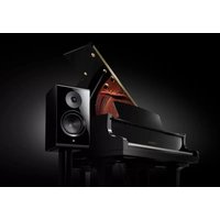
Yamaha HTY-7030 Digital Sound Projector challenges this preconception that complicated speaker setup and troublesome wiring go hand-in-hand with the enjoyment of multi-channel surround sound.
This slimline unit does away with the need for complicated wiring and installation worries, leaving you with a unit that is not only easy to set up, but is also capable of reproducing the kind of powerful surround sound you have been waiting for from its built-in 2 woofers and 21 full-range small speakers.
You can fine-tune the parameters of this unit to adjust the delay time for separate sound beams, resulting in highly directional sound that comes in on the listening position from all directions.
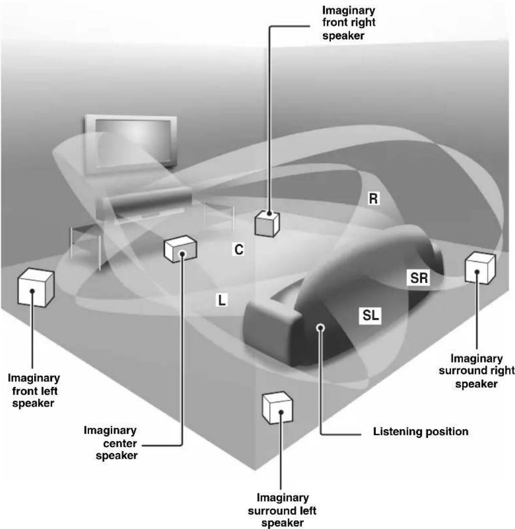
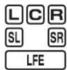
The HTY-7030 projects sound beams containing surround sound information for the front right (R), front left (L), surround right (SR), and surround left (SL) speaker positions, which are reflected off the walls of your listening room before reaching the actual listening position. With the addition of center (C) sound beams, this Digital Sound Projector creates true-to-life 5.1-channel surround sound that makes you feel as if there are actual speakers around the room.
Sit back and enjoy the real sound experience of this simple, yet stylish Digital Sound Projector.
Features
Digital Sound Projector™
The Digital Sound Projector technology allows one slim unit to control and steer multiple channels of sound to generate multi-channel surround sound, thus eliminates the need for satellite loudspeakers and cabling normally associated with conventional surround sound systems. This unit also employs the beam modes that let you enjoy the surround sound (5 Beam, Stereo plus 3 Beam, 3 Beam, and My Surround), 2-channel and 5-channel stereo playback, and My Beam.
My Surround
In addition to the above mentioned beam modes, this unit is equipped with My Surround beam mode that allows you to enjoy surround system even in a small listening area.
My Beam
This unit employs My Beam that ensures a clear sound in a noisy environment. You can adjust the beam angle manually or automatically using the supplied remote control to the maximum of 45^ , rightward and leftward.
Cinema DSP
This unit employs the Cinema DSP technology developed by Yamaha Electronics Corp. that lets you experience movies at home with all the original dramatic sound impact.
HDMI™ (High-Definition Multimedia Interface)
◆ HDMI interface for standard, enhanced, or high-definition video (including 1080p video signal transmission) as well as multi-channel digital audio based on HDCP
◆ Simple and easy connections with HDMI supported external components
◆ Functional link with an HDMI control-compatible TV
Versatile Remote Control
The supplied remote control comes with preset remote control codes used to control the DVD player, VCR, cable TV tuner, and digital satellite tuner connected to this unit. In addition, the remote control is equipped with the macro capability that enables a series of operations with the press of a single button.
AUTO SETUP (IntelliBeam)
This unit employs the automatic sound beam and acoustic optimization technology with the aid of the supplied IntelliBeam microphone. You can avoid troublesome listening-based speaker setup and achieve highly accurate sound beam adjustments that best match your listening environment.
Compatibility with the Newest Technologies
This unit employs decoders compatible with Dolby Digital, DTS, Dolby Pro Logic, Dolby Pro Logic II, DTS Neo:6, Music Enhancer, and Neural Surround.
◆ Dolby Digital
This is the standard audio signal format used on various digital media such as DVD, Blu-Ray, and HD DVD. This surround technology delivers high-quality digital audio for up to 5.1 discrete channels to produce a directional and more realistic effect.
◆ DTS
This is the standard audio signal format used on various digital media such as DVD, Blu-Ray, and HD DVD. This surround technology delivers high-quality digital audio for up to 5.1 discrete channels to produce a directional and more realistic effect.
♦ Dolby Pro Logic
This sophisticated, matrix decoding technology up-converts any 2-channel source audio to a 5.1-channel full bandwidth playback, resulting in a surround sound experience.
♦ Dolby Pro Logic II
This is a redesigned version of Dolby Pro Logic that employs 2 stereo surround channels, a subwoofer, and a greatly enhanced steering logic. This improved technology provides an exceptionally stable sound field that simulates 5.1 to a much greater degree than the original Dolby Pro Logic.
◆ DTS Neo:6
This technology decodes the conventional 2-channel sources for 6-channel playback, enabling playback with the full-range channels with higher separation. Music mode and Cinema mode are available to play back music and movie sources respectively.
◆ Music Enhancer to restore the original depth and width of compression artifacts such as the MP3 format.
◆ Neural Surround decoder (U.S.A and Canada models only)
Sophisticated FM tuner
◆ 40-station random and direct preset tuning
◆ Automatic preset tuning
◆ Radio Data System capability (Europe model only)
XM™ Satellite Radio
(U.S.A. and Canada models only)
◆ XM Satellite Radio tuning capability (using the XM Mini-Tuner Dock, and Antenna sold separately by XM Satellite Radio)
◆ Neural Surround decoder to play back the XM HD content of XM Satellite Radio broadcasts in multi-channels, resulting in a full surround sound experience
◆ XM Satellite Radio information displaying capability
iPod™ Controlling Capability
(U.S.A., Canada, and Australia models only)
♦ DOCK terminal to connect a Yamaha iPod universal dock (such as the YDS-10, sold separately), which supports iPod (Click and Wheel), iPod nano, and iPod mini
◆ Playback information displaying capability
◆ Battery charging capability
Features
IntelliBeam
The "Intelligeand IntelliBeam" are trademarks of YAMAHA Corporation.
CINEMADSP
The “Logo” and “Cinema DSP” are registered trademarks of YAMAHA Corporation.

Manufactured under license from Dolby Laboratories. "Dolby", "Pro Logic", and the double-D symbol are trademarks of Dolby Laboratories.

“DTS” and “Neo:6” are registered trademarks of DTS, Inc.
HDMI
"HDMI", the "HDMI" logo and "High-Definition Multimedia Interface" are trademarks or registered trademarks of HDMI Licensing LLC.

Manufactured under license from 1 Ltd. Worldwide patents applied for.
The “ ”Logo and “Digital Sound Projector TM” are trademarks of 1 Ltd.

TruBass, SRS and the “symbol” are registered trademarks of SRS Labs, Inc. TruBass technology is incorporated under license from SRS Labs, Inc.
EUPHONY
EUPHONY™ is a trademark of DiMAGIC Co., Ltd.
Using this manual
Notes
- This manual describes how to connect and operate this unit. For details regarding the operation of external components, refer to the supplied owner's manual for each component.
- Operations in this manual use keys on the supplied remote control of this unit unless otherwise specified.
• indicates a tip for your operation. - This manual is printed prior to production. Designs and specifications are subject to change in part as a result of improvements, etc. In case of differences between the manual and the product, the product has priority.
1 Install this unit in your listening room.
See "Installation" on page 16.

2 Connect this unit to your TV and other external components.
See "Connections" on page 19.

3 Prepare the remote control and turn on the power of this unit.
See "Getting started" on page 30.

4 Run AUTO SETUP.
See "AUTO SETUP (IntelliBeam)" on page 35.

5 Play back a source.
See "Playback" on page 45.

6 Change the beam modes and/or CINEMA DSP settings.
See “Enjoying surround sound” on page 54.

If you want to make additional settings and adjustments
7 Run MANUAL SETUP to fine-tune settings and/or set remote control codes.
See “MANUAL SETUP” on page 72 and “Remote control features” on page 96.
Supplied accessories
Check that you have received all of the following parts.
Remote control (×1)
(U.S.A. and Canada models)
Batteries (×2) (AA, R6, UM-3)

Demonstration DVD
(×1)

Fasteners (×4)
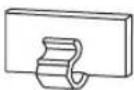
Cable clamp (×1)
IntelliBeam microphone (×1)

Cardboard microphone stand (×1)

natural_image
Simple line drawing of a metal profile with a circular hole and two parallel slots (no text or symbols)Indoor FM antenna (×1)

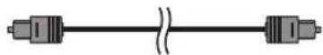
Optical cable (×1)

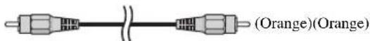
Digital audio pin cable (×1)

natural_image
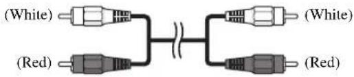
Illustration of a coiled cable with two connectors, labeled (Orange) at the end (no other text or symbols)Audio pin cable (×1)

natural_image
Coiled cable with three connectors, labeled (White/Red) at the end (no other text or symbols)OSD* video pin cable (×1)

natural_image
Illustration of a coiled cable with two connectors, labeled (Yellow) at the bottom (no other text or symbols)*OSD: On-Screen Display
QUICK REFERENCE GUIDE
* The number of provided languages varies depending on the model.
Controls and functions
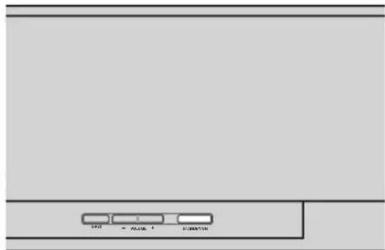
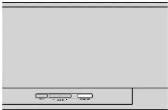
Front panel
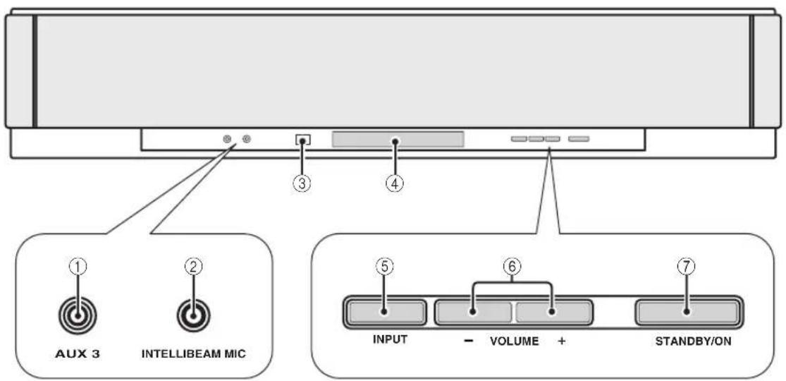
①AUX 3 input jack
Connect your portable audio player (see page 26).
②INTELLIBEAM MIC jack
Connect the supplied IntelliBeam microphone for AUTO SETUP (see page 36).
③Remote control sensor
Receives infrared signals from the remote control.
④Front panel display
Shows information about the operational status of this unit.
⑤INPUT
Press repeatedly to switch between input sources (see page 45).
Outputs a test tone to experience the sound beam (see page 91).
⑥VOLUME +/-
Controls the volume level of all audio channels (see page 47).
⑦STANDBY/ON
Turns on the power of this unit or sets it to the standby mode (see page 31).
Notes
- When you turn on this unit, you will hear a click sound followed by the 4 to 5-second interval before sound reproducing.
- In the standby mode, this unit consumes a small amount of power in order to receive infrared signals from the remote control or to search for HDMI signals.
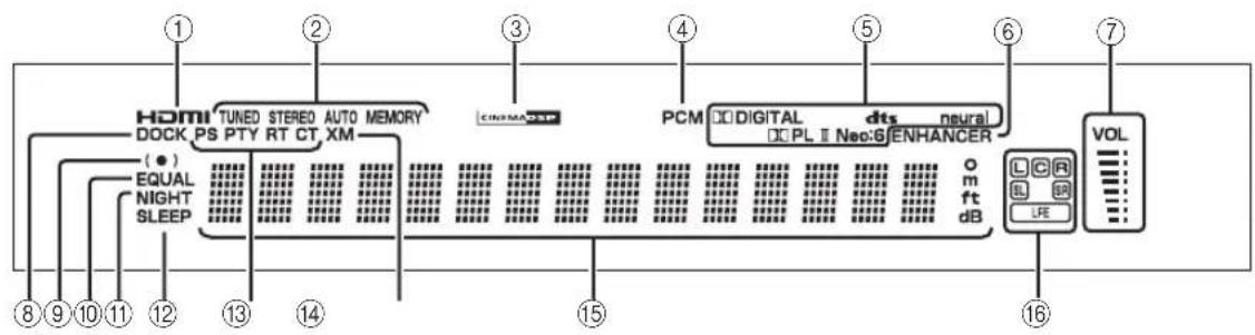
Front panel display
flowchart
graph LR
    A["①"] --> B["HDMI"]
    B --> C["DOCK PS PTY RT CT XM"]
    C --> D["②"]
    D --> E["TUNED STEREO AUTO MEMORY"]
    E --> F["③"]
    F --> G["④"]
    G --> H["PCM"]
    H --> I["⑤"]
    I --> J["⑥"]
    J --> K["VOL"]
    K --> L["⑦"]
    L --> M["⑧"]
    M --> N["⑨"]
    N --> O["⑩"]
    O --> P["⑪"]
    P --> Q["⑫"]
    Q --> R["⑬"]
    R --> S["⑭"]
    S --> T["⑮"]
    T --> U["⑯"]
    U --> V["⑰"]
    V --> W["⑱"]
    W --> X["⑲"]
    X --> Y["⑳"]
    Y --> Z["㉑"]
    Z --> AA["㉒"]
    AA --> AB["㉓"]
    AB --> AC["㉔"]
    AC --> AD["㉕"]
    AD --> AE["㉖"]
    AE --> AF["㉗"]
    AF --> AG["㉘"]
    AG --> AH["㉙"]
    AH --> AI["㉚"]
    AI --> AJ["㉛"]
    AJ --> AK["㉜"]
    AK --> AL["㉝"]
①HDMI indicator
Lights up when the signal of the selected input source is input at the HDMI IN jack(s).
②TUNER indicators
FM: Light up when this unit is receiving an FM broadcast. XM: MEMORY flashes during the XM preset operation (U.S.A. and Canada models only).
③CINEMA DSP indicator
Lights up when a sound field program is selected (see page 64).
④PCM indicator
Lights up when this unit is reproducing PCM (Pulse Code Modulation) digital audio signals.
⑤Decoder indicators
Light up when the corresponding decoder operates (see page 56).
Note
The neural decoder is available for the U.S.A. and Canada models only.
⑥ENHANCER indicator
Lights up when the Music Enhancer is selected (see page 66).
⑦Volume level indicator
Displays the current volume level.
⑧DOCK indicator
(U.S.A., Canada, and Australia models only)
Lights up when your iPod (Click and Wheel), iPod nano, or iPod mini is connected to this unit via the DOCK terminal on this unit.
⑨SRS TruBass indicator
Lights up when TruBass is turned on (see page 79).
⑩EQUAL indicator
Lights up when the TV volume equal mode is selected (see page 67).
⑪NIGHT indicator
Lights up when one of the night listening enhancers is selected (see page 67).
⑫SLEEP indicator
Lights up when the sleep timer is set (see page 68).
⑬ Radio Data System indicators (Europe model only)
Show the current Radio Data System status.
⑭XM indicator
(U.S.A. and Canada models only)
Lights up when XM is selected as the input source.
⑮Multi-information display
Shows information with alphanumeric characters when you adjust the parameters of this unit.
⑯Input channel indicators
Show information when you adjust the parameters of this unit. The channel component of the current digital input signal is displayed (see page 56).
The image contains a graphical symbol: a light bulb with radiating lines and a lightning bolt inside, accompanied by the text '1' at the bottom left. There is no textual content to extract or process according to the OCR guidelines.
You can adjust the brightness and display setting of the front panel display using the F.DISPLAY SET parameter in MANUAL SETUP (see page 83).
Rear panel
The illustration below shows the rear panel of the U.S.A. and Canada models.
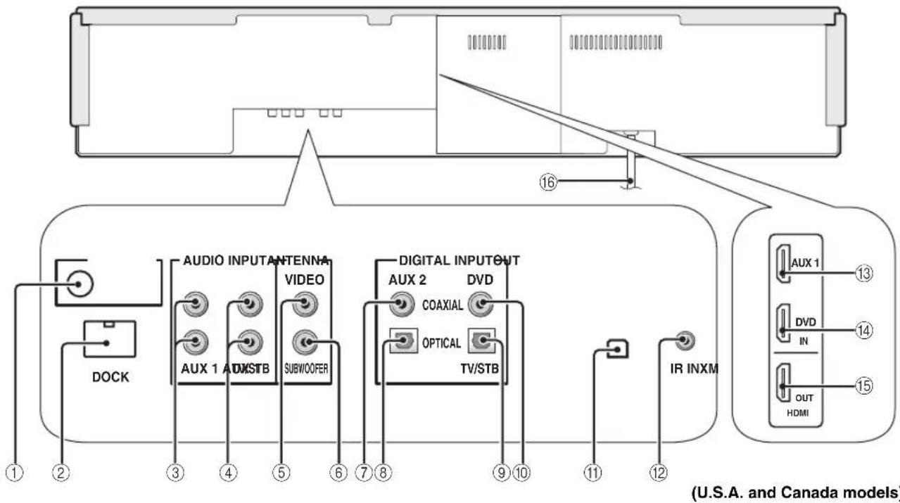
①ANTENNA jack
Connect the FM antenna (see page 29).
②DOCK terminal
(U.S.A., Canada, and Australia models only)
Connect the Yamaha iPod universal dock (such as YDS-10, sold separately) (see page 2 in the Reference Guide).
③AUX 1 AUDIO INPUT jacks
Connect an external component via an analog connection (see page 23).
④TV/STB AUDIO INPUT jacks
Connect your TV, digital satellite tuner, or cable TV tuner via an analog connection (see pages 22 and 24).
⑤VIDEO OUT jack
Connect to the video input jack of your TV to display the OSD of this unit (see page 22).
⑥SUBWOOFER OUT jack
Connect your subwoofer (see page 28).
⑦AUX 2 COAXIAL DIGITAL INPUT jack
Connect an external component via a coaxial digital connection (see page 27).
⑧AUX 1 OPTICAL DIGITAL INPUT jack
Connect an external component via an optical digital connection (see page 27).
⑨TV/STB OPTICAL DIGITAL INPUT jack
Connect your TV, digital satellite tuner, or cable TV tuner via an optical digital connection (see pages 22 and 24).
⑩DVD COAXIAL DIGITAL INPUT jack
Connect your DVD player via a coaxial digital connection (see page 23).
⑪XM antenna jack
(U.S.A and Canada models only)
Connect your XM Mini-Tuner Dock (sold separately) (see page 5 in the Reference Guide).
⑫IR IN terminal
(U.S.A and Canada models only)
This is a control expansion terminal for commercial use only (see page 29).
⑬AUX 1 HDMI IN jack
Connect your digital satellite tuner, cable TV tuner, digital air wave tuner, or game console via an HDMI connection (see page 21).
⑭DVD HDMI IN jack
Connect your DVD player via an HDMI connection (see page 21).
⑮HDMI OUT jack
Connect to the HDMI IN jack on your HDMI component such as a TV or a projector connected to this unit (see page 21).
⑯AC power supply cable
Connect to the AC wall outlet (see page 29).
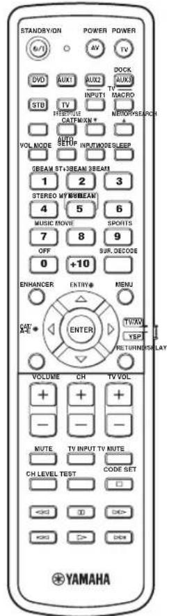
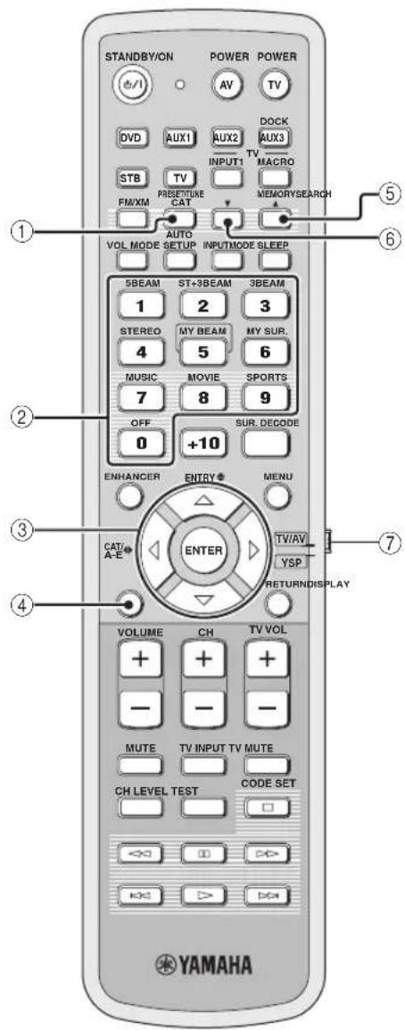
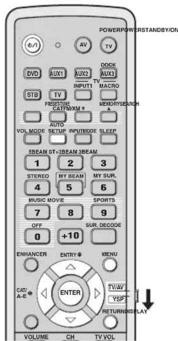
Remote control (Europe, Australia, Asia, and Korea models)
This section describes the functions of the remote control used to control this unit. Some buttons marked with an asterisk (*) share the common functions between the YSP and TV/AV operation modes (29).

You can also control other components using the remote control once you set the appropriate remote control codes. See "Controlling other components" on page 97 for details.
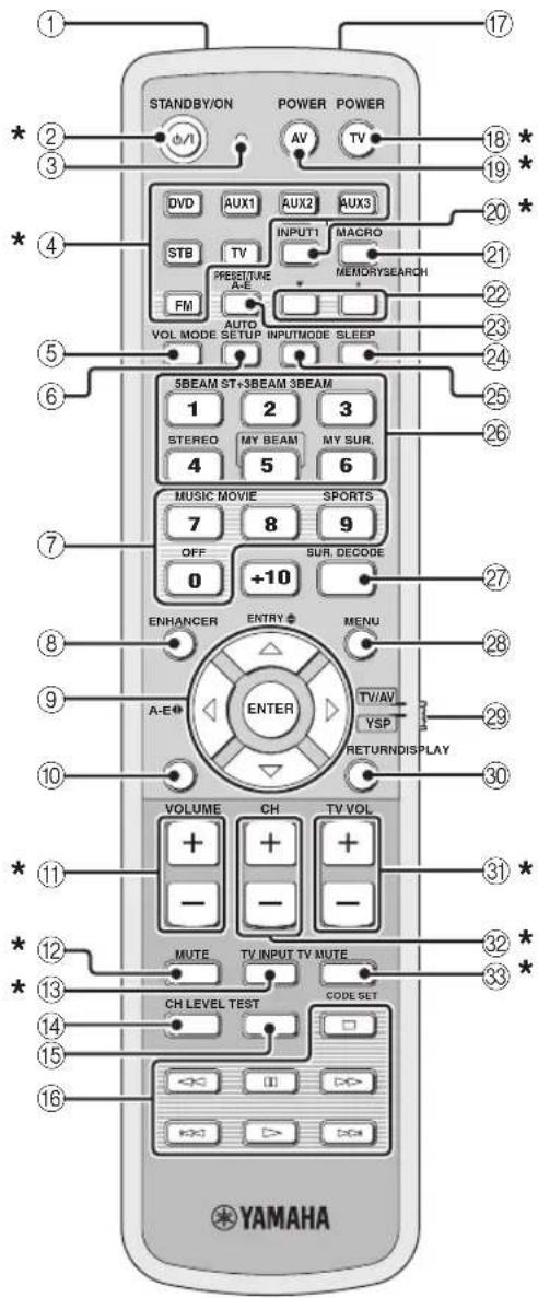
①Infrared window
Outputs infrared control signals. Aim this window at the component you want to operate.
②STANDBY/ON
Sets this system to the standby mode (see page 31).
③Transmission indicator
Lights up when infrared control signals are being output.
④Input selector buttons
Use to select an input source (DVD, AUX1, AUX2, AUX3, STB, TV, or FM).
⑤VOL MODE
Turns on or off the volume modes (see page 67).
⑥AUTO SETUP
Enters the AUTO SETUP menu (see page 35).
⑦CINEMA DSP program buttons
Select the CINEMA DSP programs (see page 63).
⑧ENHANCER
Turns on or off the Music Enhancer (see page 66).
⑨ Cursor buttons ↗, ENTER
Select and adjust SET MENU items.
⑩DISPLAY
Displays information on the selected input signal.
⑪VOLUME +/-
Increases or decreases the volume level of this unit (see page 47).
⑫MUTE
Mutes the sound. Press again to restore the audio output to the previous volume level (see page 47).
⑬TV INPUT
Toggles between the input sources on the TV (see page 97).
⑭CH LEVEL
Adjusts the volume level of each channel (see page 85).
⑮TEST
Outputs a test tone when adjusting the output level of each channel (see page 84).
⑯DVD player/VCR control buttons
Control your DVD player or VCR (see pages 98 and 99).
⑰My Beam microphone
Collects the test tones from this unit when using the My Beam auto-adjust function (see page 61).
⑱TV POWER
Turns on the power of your TV or sets it to the standby mode (see page 97).
⑲AV POWER
Turns on the power of the selected component or sets it to the standby mode (see pages 98 and 99).
⑳INPUT1
Switches the input source on your TV (see page 97).
②1MACRO
Use to set the TV macro (see page 100).
⑳/▲
Switches the preset station number (1 to 8) when this unit is receiving an FM broadcast (see page 52).
②3A-E
Switches the preset station group (A to E) when this unit is receiving an FM broadcast (see page 52).
⑳SLEEP
Sets the sleep timer (see page 68).
⑲INPUTMODE
Toggles between input modes (AUTO, DTS, and ANALOG) (see page 87).
②6Beam mode buttons
Change the beam mode settings (see pages 54, 60, and 61).
⑳SUR. DECODE
Selects the surround mode for playback (see page 57).
⑳MENU
Displays the setup menu on your TV monitor (see pages 37 and 73).
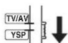
⑲Operation mode selector
Selects the operation mode of this unit. Select YSP when operating this unit and select TV/AV when operating your TV or other AV components.
③0RETURN
Selects sleep timer settings or returns to the previous SET MENU screen.
③1 TV VOL +/-
Adjusts the volume level of your TV (see page 97).
③2CH+/-
Changes the channels of your TV, digital satellite tuner, cable TV tuner, or VCR (see pages 97 and 99).
③3TV MUTE, CODE SET
Mutes the audio output of your TV (see page 97). Sets up remote control codes (see page 96).
Note
The functions ② and ③ are available only when the FM stations are preset.
Controls and functions
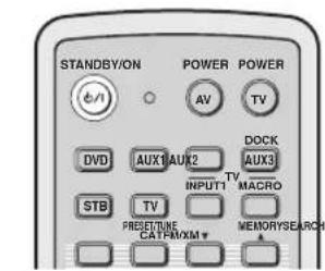
This section describes the functions of the remote control used to control FM, Radio Data System, or iPod when the TV/AV mode is selected with the operation mode selector (⑦). Note that the Radio Data System controls are available for Europe model only, and the iPod controls are available for Australia model only.
![STANDBY/ON POWER POWER AV TV DVD AUX1 AUX2 AUX3 STB TV INPUT1 MACRO PRESET/TURE A-E MEMORYSEARCH FM AUTO INPUTMODE SLEEP VOL MODE SETUP INPUTMODE SLEEP 5BEAM ST+3BEAM 3BEAM 1 2 3 STEREO MY BEAM MY SUR. 4 5 6 MUSIC MOVIE SPORTS 7 8 9 OFF SUR. DECODE 0 +10 ENHANCER ENTRY MENU A-E ENTER TV/AV YSP RETURNDISPLAY VOLUME CH TV VOL + + + - - - MUTE TV INPUT TV MUTE CH LEVEL TEST CODE SET < > [ ] [ > ] [ > ] [ > ] [ > ] [ > ] [ > ] [ > ] [ > ] [ > ] [ > ] [ > ] [ > ] [ > ] [ > ] [ > ] [ > ] [ > ] [ > ] [ > ] [ > ] [ > ] [ > ] [ > ] [ > ] [ > ] [ > ] [ > ] [ > ] [ > ] [ > ] [ > ] [ > ] [ > ] [ > ] [ > ] [ <] [ ] [ ] [ ] [ ] [ ] [ ] [ ] [ ] [ ] [ ] [ ] [ ] [ ] [ ] [ ] [ ] [ ] [ ] [ ] [ ] [ ] [ ] [ ] [ ] [ ] [ ] [ ] [ ] [ ] [ ] [ ] [ ] [ ] [ ] [ ] [ ] [ ] [ ] [ ] [ ] [ ] [ ] [ ] [ ] [ ] [ ] [ ] [ ] [ ] [ ] [ ] YAMAHA](/content/2026/02/375754/images/9fa0ccd64cd8f1c14c556cb935645e1b5d1067f3232cbf219a2dc5c49ababd06.jpg)
①PRESET/TUNE
FM: Switches between the preset search mode and the frequency search mode (see pages 49 to 52).
②Numeric buttons
FM: Enter numbers.
③Cursor buttons ↗/ ENTER
FM: Use ENTRY ♦(/) to change the preset station number (1 to 8) or frequency level (see pages 49 to 52). Use A-E ♦(/) to change the preset station group (A to E) (see pages 51 and 52). Use ENTER to confirm the input above.

These functions are also available when this unit is receiving the Radio Data System (see page 52) or playing back your iPod (see page 3 in the Reference Guide).
④DISPLAY
Radio Data System and iPod: Displays information when this unit is receiving the Radio Data System (see page 52) or playing back your iPod (see page 3 in the Reference Guide).
⑤MEMORY
FM: Stores the preset stations (see pages 50 and 51).

This function is also available when this unit is receiving the Radio Data System (see page 52).
⑥SEARCH
FM: Switches between automatic and manual tuning (see page 49).
⑦Operation mode selector
Selects the operation mode of this unit. Select YSP when operating this unit and select TV/AV when operating your TV or other AV components.
Remote control (U.S.A. and Canada models)
This section describes the functions of the remote control used to control this unit. Some buttons marked with an asterisk (*) share the common functions between the YSP and TV/AV operation modes (29).

You can also control other components using the remote control once you set the appropriate remote control codes. See "Controlling other components" on page 97 for details.
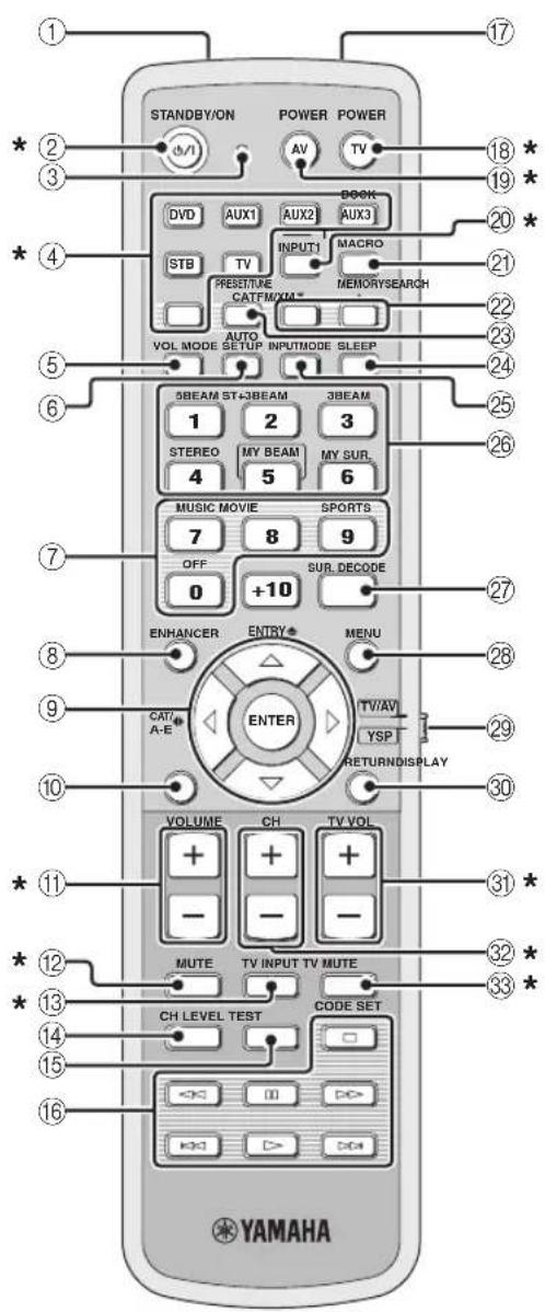
①Infrared window
Outputs infrared control signals. Aim this window at the component you want to operate.
②STANDBY/ON
Sets this system to the standby mode (see page 31).
③Transmission indicator
Lights up when infrared control signals are being output.
④Input selector buttons
Use to select an input source (DVD, AUX1, AUX2, AUX3/DOCK, STB, TV, or FM/XM).
⑤VOL MODE
Turns on or off the volume modes (see page 67).
⑥AUTO SETUP
Enters the AUTO SETUP menu (see page 35).
⑦Sound field program buttons
Select the sound field programs (see page 63).
⑧ENHANCER
Turns on or off the Music Enhancer (see page 66).
⑨Cursor buttons ↗, ENTER
Select and adjust SET MENU items.
⑩DISPLAY
Displays information on the selected input signal.
⑪VOLUME +/-
Increases or decreases the volume level of this unit (see page 47).
⑫MUTE
Mutes the sound. Press again to restore the audio output to the previous volume level (see page 47).
⑬TV INPUT
Toggles between the input source on your TV (see page 97).
⑭CH LEVEL
Adjusts the volume level of each channel (see page 85).
⑮TEST
Outputs a test tone when adjusting the output level of each channel (see page 84).
Controls and functions
⑯DVD player/VCR control buttons
Control your DVD player or VCR (see pages 98 and 99).
⑰My Beam microphone
Collects the test tones from this unit when using the My Beam auto-adjust function (see page 61).
⑱TV POWER
Turns on the power of your TV or sets it to the standby mode (see page 97).
⑲AV POWER
Turns on the power of the selected component or sets it to the standby mode (see pages 98 and 99).
⑳INPUT1
Switches the input source on your TV (see page 97).
②1MACRO
Use to set the TV macro (see page 100).
⑳/▲
Switches the preset station number (1 to 8) when this unit is receiving an FM broadcast or XM channel (see page 52).
②3CAT
Switches the preset station group (A to E) when this unit is receiving an FM broadcast or XM channel (see page 52).
⑳SLEEP
Sets the sleep timer (see page 68).
⑲INPUTMODE
Toggles between input modes (AUTO, DTS, and ANALOG) (see page 87).
⑳Beam mode buttons
Change the beam mode settings (see pages 54, 60, and 61).
⑳SUR. DECODE
Selects the surround mode for playback (see page 57).
⑳MENU
Displays the setup menu on your TV monitor (see pages 37 and 73).
⑲Operation mode selector
Selects the operation mode of this unit. Select YSP when operating this unit and select TV/AV when operating your TV or other AV components.
③0RETURN
Selects sleep timer settings or returns to the previous SET MENU screen.
③1TV VOL +/-
Adjusts the volume level of your TV (see page 97).
③2CH+/-
Changes the channels of your TV, digital satellite tuner, cable TV tuner, or VCR (see pages 97 and 99).
③3TV MUTE, CODE SET
Mutes the audio output of your TV (see page 97). Sets up remote control codes (see page 96).
Note
The functions ② and ③ are available only when the FM/XM stations are preset.
This section describes the functions of the remote control used to control FM, XM Satellite Radio, or iPod when the TV/AV mode is selected with the operation mode selector (⑦).
①PRESET/TUNE
FM: Switches between the preset search mode and the frequency search mode (see pages 49 to 52).
②Numeric buttons
FM, XM: Enter numbers.
③Cursor buttons ▽ / ◀ ▷ /
FM: Use ENTRY ♦( / ) to change the preset station number (1 to 8) or frequency level (see pages 49 to 52). Use CAT/A-E ⬆/ (to change the preset station group (A to E) (see pages 51 and 52). Use ENTER to confirm the input above.
XM: Use ENTRY /ʌto select XM channels in All Channel Search mode/Category Search mode, and to select the preset channel number (1 to 8) in Preset Search mode. Use CAT/A-E /ʌto select XM categories in All Channel Search mode/Category Search mode, and to select the preset channel group (A to E) in Preset Search mode. Use ENTER to confirm the input above (see pages 7 and 8 in the Reference Guide).
[Non-Text]
These functions are also available when this unit is playing back your iPod (see page 3 in the Reference Guide).
④DISPLAY
XM and iPod: Displays information when this unit is receiving an XM channel (see page 10 in the Reference Guide) or playing back your iPod (see page 3 in the Reference Guide).
⑤MEMORY
FM: Stores the preset stations (see pages 50 and 51). XM: Use to store the preset stations (see page 9 in the Reference Guide).
⑥SEARCH
FM: Switches between automatic and manual tuning (see page 49).
XM: Switches between search modes (All Channel Search, Category Search, and Preset Search) (see pages 7 and 8 in the Reference Guide).
⑦Operation mode selector
Selects the operation mode of this unit. Select YSP when operating this unit and select TV/AV when operating your TV or other AV components.
Installation
This section describes a suitable installation location to install this unit using a metal wall bracket, a rack or a stand. Depending on your installation environment, connections with external components can be done before installing this unit. We recommend that you temporarily place and arrange all components, including this unit, in order to decide which procedure should come first. Especially when you make a connection over HDMI, we recommend that you make a connection first before installation (see page 21).
Before installing this unit
This unit creates surround sound by reflecting projected sound beams off the walls of your listening room. The surround sound effects produced by this unit may not be sufficient when this unit is installed in the following locations.
• Rooms with walls inadequate for reflecting sound beams
• Rooms with acoustically absorbent walls
- Rooms with measurements outside the following range: W (3 to 7 m (10 to 23 ft)) x H (2 to 3.5 m (7 to 11.5 ft)) x D (3 to 7 m (10 to 23 ft))
• Rooms with less than 1.8 m (6 ft) from the listening position to this unit
• Rooms where objects such as furniture are likely to obstruct the path of sound beams
• Rooms where the listening position is close to the walls
- Rooms where the listening position is not in front of this unit

- You can enjoy surround sound by selecting My Surround (see page 55) as the beam mode even if your listening room may not fulfill the above conditions (except when the listening position is not directly facing toward the front of this unit).
- You can also enjoy surround sound by selecting 2-channel or 5-channel stereo playback (see page 60) or My Beam (see page 61) as the beam mode even if your listening room may not fulfill the above conditions.
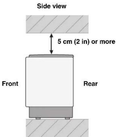
Make sure you leave an adequate amount of ventilation space so that heat can escape. Make at least 5 cm (2 in) of space above or below this unit.
Notes
- We do not recommend putting this unit directly on the floor of your listening room. Please install this unit using a metal wall bracket, a rack, or a stand.
- This unit weighs 11.5 kg (25 lbs 6 oz). Be sure to install this unit where it will not fall subject to vibrations, such as from an earthquake, and where it is out of the reach of children.
- When using a cathode-ray tube (CRT) TV, do not install this unit directly above your TV.
- This unit is shielded against magnetic rays. However, if the picture on your TV screen becomes blurred or distorted, we recommend moving this unit away from your TV.
Installing this unit
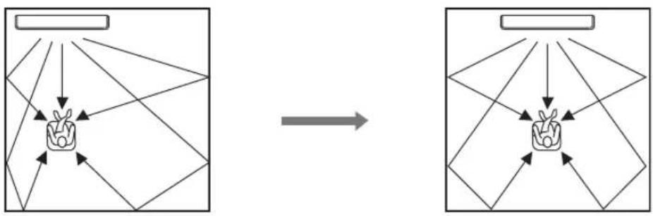
Install this unit where there are no obstacles such as furniture obstructing the path of sound beams. Otherwise, the desired surround sound effects may not be achieved. You may install this unit in parallel with the wall or in the corner.
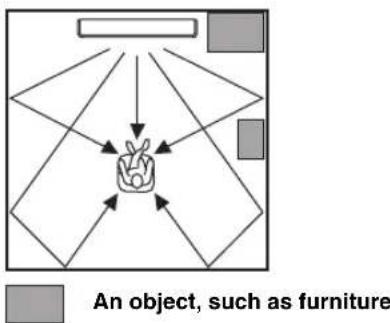
Parallel installation
Install this unit in the exact center of the wall when it is measured from the left and right corners.
flowchart
graph TD
    A["Hand holding a bag"] --> B["Geometric shapes"]
    B --> C["Arrow to top of hand"]
    C --> D["Arrow to bottom of hand"]
    D --> E["Arrow to bottom of hand"]
    E --> F["Arrow to bottom of hand"]
    F --> G["Arrow to bottom of hand"]
    G --> H["Arrow to bottom of hand"]
    H --> I["Arrow to bottom of hand"]
    I --> J["Arrow to bottom of hand"]
    J --> K["Arrow to bottom of hand"]
    K --> L["Arrow to bottom of hand"]
    L --> M["Arrow to bottom of hand"]
    M --> N["Arrow to bottom of hand"]
    N --> O["Arrow to bottom of hand"]
    O --> P["Arrow to bottom of hand"]
    P --> Q["Arrow to bottom of hand"]
    Q --> R["Arrow to bottom of hand"]
    R --> S["Arrow to bottom of hand"]
    S --> T["Arrow to bottom of hand"]
    T --> U["Arrow to bottom of hand"]
    U --> V["Arrow to bottom of hand"]
    V --> W["Arrow to bottom of hand"]
    W --> X["Arrow to bottom of hand"]
    X --> Y["Arrow to bottom of hand"]
    Y --> Z["Arrow to bottom of hand"]
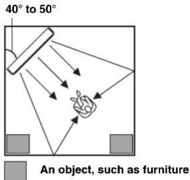
Corner installation
Install this unit in the corner at a 40^ to 50^ angle from the adjacent walls.
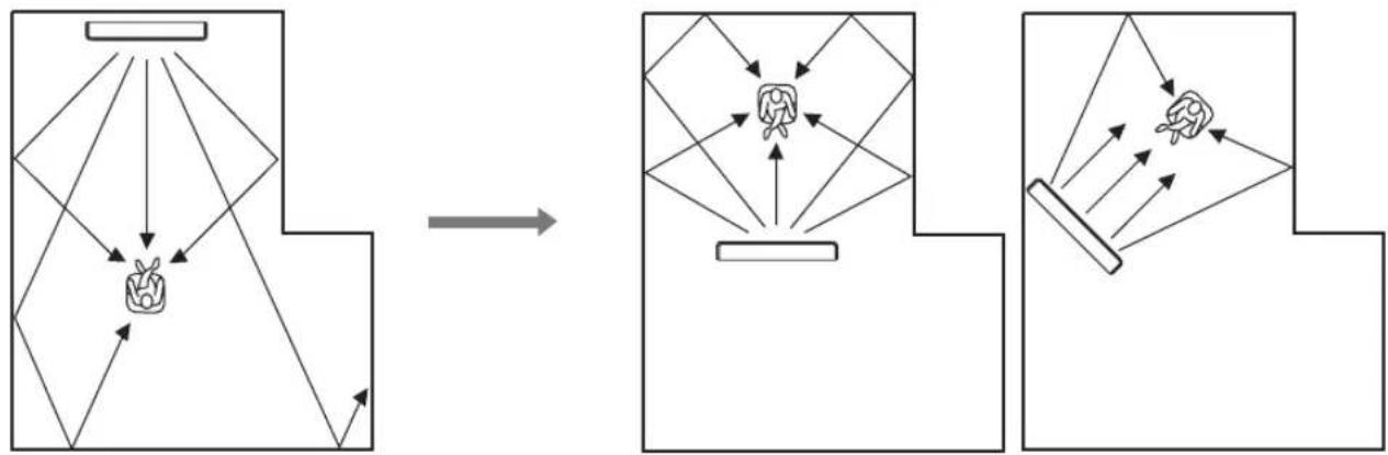
■ Installation examples
Example 1
Install this unit as close to the exact center of the wall as possible.
flowchart
graph TD
    A["Rectangular Object"] --> B["Object with Arrow"]
    B --> C["Arrow Right"]
    C --> D["Object with Arrow"]
    D --> E["Arrow Left"]
    E --> F["Object with Arrow"]
    F --> G["Arrow Up"]
    G --> H["Object with Arrow"]
    H --> I["Arrow Down"]
    I --> J["Object with Arrow"]
    J --> K["Arrow Left"]
    K --> L["Object with Arrow"]
    L --> M["Arrow Up"]
    M --> N["Object with Arrow"]
    N --> O["Arrow Down"]
    O --> P["Object with Arrow"]
    P --> Q["Arrow Up"]
    Q --> R["Object with Arrow"]
    R --> S["Arrow Down"]
    S --> T["Object with Arrow"]
Example 2
Install this unit so that the sound beams can be reflected off the walls.
flowchart
graph TD
    A["Object Tracking"] --> B["Object Detection"]
    B --> C["Object Tracking with Object Recognition"]
    C --> D["Object Detection with Object Recognition"]
    D --> E["Object Tracking with Object Recognition"]
    E --> F["Object Detection with Object Recognition"]
    F --> G["Object Tracking with Object Recognition"]
    G --> H["Object Detection with Object Recognition"]
    H --> I["Object Tracking with Object Recognition"]
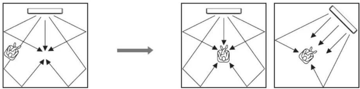
Example 3
Install this unit as close to the exact front of your normal listening position as possible.
flowchart
graph TD
    A["Hand gestures"] --> B["Arrow to central node"]
    B --> C["Arrow to right"]
    C --> D["Arrow to left"]
    D --> E["Arrow to right"]
    E --> F["Arrow to right"]
    F --> G["Arrow to right"]
    G --> H["Arrow to right"]
    H --> I["Arrow to right"]
    I --> J["Arrow to right"]
    J --> K["Arrow to right"]
    K --> L["Arrow to right"]
    L --> M["Arrow to right"]
    M --> N["Arrow to right"]
    N --> O["Arrow to right"]
    O --> P["Arrow to right"]
    P --> Q["Arrow to right"]
    Q --> R["Arrow to right"]
    R --> S["Arrow to right"]
    S --> T["Arrow to right"]
    T --> U["Arrow to right"]
Installation
■ Using a metal wall bracket
You can use the optional metal wall bracket to mount this unit on the wall in your listening room.
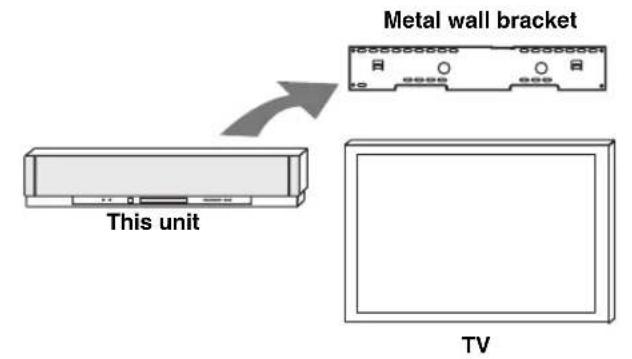
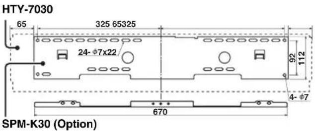

Refer to the instructions supplied with the metal bracket for details on how to attach the metal bracket to the wall or how to attach this unit to the metal bracket.
■ Using a stand
You can mount your TV on a stand placed on a commercially available rack and install this unit under your TV.
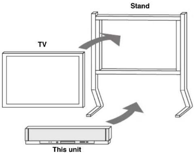

Refer to the instructions supplied with the stand for details on how to install the stand or how to mount and the TV on the stand.
■ Using a rack
You can install this unit either above or under your TV in a commercially available rack.
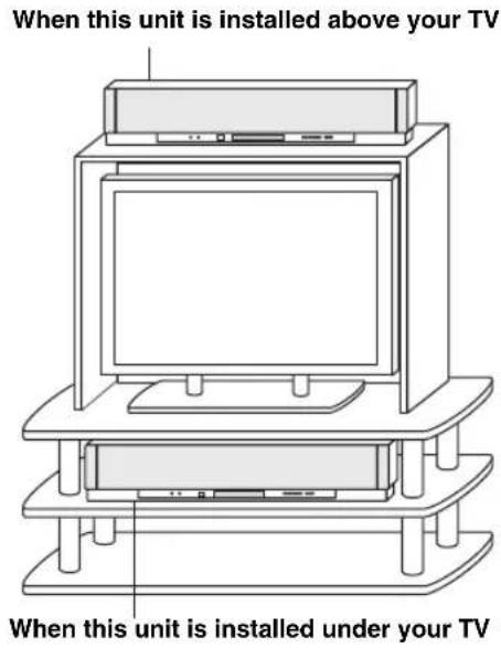
Note
Make sure that the rack is large enough to allow adequate ventilation space around this unit (see page 16) and that it is strong enough to support the weight of both this unit and your TV.
■ Affixing this unit
Peel off the film from each of the four supplied fasteners and then secure them to the bottom four corners of this unit and the top of the rack, etc.
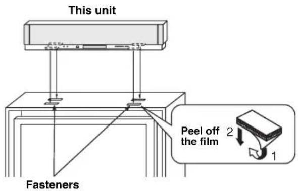
Notes
- Do not install this unit on top of a slanted surface. This unit may fall over and cause injury.
- Make sure you wipe the surface of the rack, etc. before securing the fasteners. Applying the tape to a dirty or wet surface will weaken the sticking power of the tape, and this unit may fall as a result.
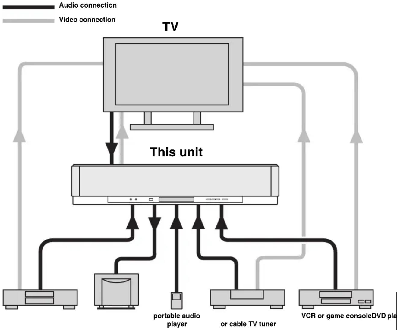
Connections
This unit is equipped with the following types of audio/video input/output jacks/terminal:
For audio input
• 2 optical digital input jacks
• 2 coaxial digital input jacks
• 2 sets of analog input jacks
- 1 universal dock terminal (U.S.A., Canada, and Australia models only)
For audio/video input
- 2 HDMI input jacks
For audio output
- 1 subwoofer output jack
• 1 HDMI output jack
For audio/video output
For video output
- 1 analog output jack
Use these jacks/terminal to connect external components such as your TV, DVD player, VCR, digital satellite tuner, cable TV tuner, digital air wave tuner, portable audio player, game console, and iPod. Further, by connecting a subwoofer to this unit, you can enjoy reinforced low-bass sounds. For details on how to connect various types of external components to this unit, see pages 21 to 28.
CAUTION
- Do not connect this unit or other components to the mains power until all connections between components are complete.
- Unplug the AC power supply cable before changing connections, moving or cleaning this unit.
flowchart
graph TD
    TV["TV"] -->|Audio connection| PC1["PC"]
    TV -->|Video connection| PC2["PC"]
    PC1 -->|This unit| PC3["PC"]
    PC2 -->|This unit| PC4["PC"]
    PC3 -->|Portable audio player| PC5["PC"]
    PC3 -->|or cable TV tuner| PC6["PC"]
    PC4 -->|VCR or game console DVD play| PC7["PC"]
    PC5 -->|VCR or game console DVD play| PC8["PC"]
    PC6 -->|VCR or game console DVD play| PC9["PC"]
    PC7 -->|VCR or game console DVD play| PC10["PC"]
    PC8 -->|VCR or game console DVD play| PC11["PC"]
    PC9 -->|VCR or game console DVD play| PC12["PC"]
    PC10 -->|VCR or game console DVD play| PC13["PC"]
    PC11 -->|VCR or game console DVD play| PC14["PC"]
    PC12 -->|VCR or game console DVD play| PC15["PC"]
    PC13 -->|VCR or game console DVD play| PC16["PC"]
    PC14 -->|VCR or game console DVD play| PC17["PC"]
    PC15 -->|VCR or game console DVD play| PC18["PC"]
    PC16 -->|VCR or game console DVD play| PC19["PC"]
    PC17 -->|VCR or game console DVD play| PC20["PC"]
    PC18 -->|VCR or game console DVD play| PC21["PC"]
    PC19 -->|VCR or game console DVD play| PC22["PC"]
    PC20 -->|VCR or game console DVD play| PC23["PC"]
    PC21 -->|VCR or game console DVD play| PC24["PC"]
    PC22 -->|VCR or game console DVD play| PC25["PC"]
    PC23 -->|VCR or game console DVD play| PC26["PC"]
    PC24 -->|VCR or game console DVD play| PC27["PC"]
    PC25 -->|VCR or game console DVD play| PC28["PC"]
    PC26 -->|VCR or game console DVD play| PC29["PC"]
    PC27 -->|VCR or game console DVD play| PC30["PC"]
    PC28 -->|VCR or game console DVD play| PC31["PC"]
    PC29 -->|VCR or game console DVD play| PC32["PC"]
    PC30 -->|VCR or game console DVD play| PC33["PC"]
    PC31 -->|VCR or game console DVD play| PC34["PC"]
    PC32 -->|VCR or game console DVD play| PC35["PC"]
    PC33 -->|VCR or game console DVD play| PC36["PC"]
    PC34 -->|VCR or game console DVD play| PC37["PC"]
    PC35 -->|VCR or game console DVD play| PC38["PC"]
    PC36 -->|VCR or game console DVD play| PC39["PC"]
    PC37 -->|VCR or game console DVD play| PC40["PC"]
    PC38 -->|VCR or game console DVD play| PC41["PC"]
    PC39 -->|VCR or game console DVD play| PC42["PC"]
    PC40 -->|VCR or game console DVD play| PC43["PC"]
    PC41 -->|VCR or game console DVD play| PC44["PC"]
    PC42 -->|VCR or game console DVD play| PC45["PC"]
    PC43 -->|VCR or game console DVD play| PC46["PC"]
    PC44 -->|VCR or game console DVD play| PC47["PC"]
    PC45 -->|VCR or game console DVD play| PC48["PC"]
    PC46 -->|VCR or game console DVD play| PC49["PC"]
    PC47 -->|VCR or game console DVD play| PC50["PC"]
    PC48 -->|VCR or game console DVD play| PC51["PC"]
    PC49 -->|VCR or game console DVD play| PC52["PC"]
    PC50 -->|VCR or game console DVD play| PC53["PC"]
    PC51 -->|VCR or game console DVD play| PC54["PC"]
    PC52 -->|VCR or game console DVD play| PC55["PC"]
    PC53 -->|VCR or game console DVD play| PC56["PC"]
    PC54 -->|VCR or game console DVD play| PC57["PC"]
    PC55 -->|VCR or game console DVD play| PC58["PC"]
    PC56 -->|VCR or game console DVD play| PC59["PC"]
    PC57 -->|VCR or game console DVD play| PC60["PC"]
    PC58 -->|VCR or game console DVD play| PC61["PC"]
    PC59 -->|VCR or game console DVD play| PC62["PC"]
    PC60 -->|VCR or game console DVD play| PC63["PC"]
    PC61 -->|VCR or game console DVD play| PC64["PC"]
    PC62 -->|VCR or game console DVD play| PC65["PC"]
    PC63 -->|VCR or game console DVD play| PC66["PC"]
    PC64 -->|VCR or game console DVD play| PC67["PC"]
    PC65 -->|VCR or game console DVD play| PC68["PC"]
    PC66 -->|VCR or game console DVD play| PC69["PC"]
    PC67 -->|VCR or game console DVD play| PC70["PC"]
    PC68 -->|VCR or game console DVD play| PC71["PC"]
    PC69 -->|VCR or game console DVD play| PC72["PC"]
    PC70 -->|VCR or game console DVD play| PC73["PC"]
    PC71 -->|VCR or game console DVD play| PC74["PC"]
    PC72 -->|VCR or game console DVD play| PC75["PC"]
    PC73 -->|VCR or game console DVD play| PC76["PC"]
    PC74 -->|VCR or game console DVD play| PC77["PC"]
    PC75 -->|VCR or game console DVD play| PC78["PC"]
    PC76 -->|VCR or game console DVD play| PC79["PC"]
    PC77 -->|VCR or game console DVD play| PC80["PC"]
Before connecting components
■ Cables used for connections
Audio/Video
A HDMI cable

Audio
1 Audio pin cable (supplied)
2 Optical cable (supplied)
3 Digital audio pin cable (supplied)
1 OSD video pin cable (supplied)

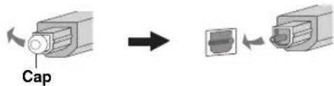
■ Notes on connecting the optical cable
- Pull out the cap before connecting the optical cable.
When you are not using the optical cable, be sure to put the cap back in place.
- When inserting the cable into the optical digital jack, make sure the direction is correct.
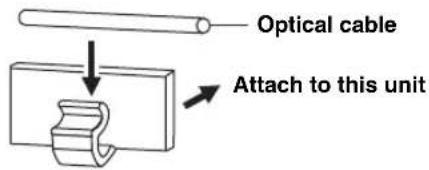
■ Affixing cables
To prevent cables from becoming unplugged, place the supplied cable clamp with the open side facing upward, attach it to the rear panel of this unit in a suitable position, and then affix cables in the cable clamp.
■ Information on HDMI™
Audio Signals
| Input source Audio signal type | |
| DVD video Dolby Digital, DTS, PCM | |
| DVD audio | 2-channel stereo(up to 96 kHz/24 bit) |
| Blu-ray DiscHD DVD | Dolby Digital, DTS, PCM |
Notes
- When CPPM copy-protected DVD audio is played back, video and audio signals may not be output depending on the type of DVD player.
- This unit is not compatible with HDCP-incompatible HDMI or DVI components.

- We recommend that you use an HDMI cable shorter than 5 m (16 ft) with the HDMI logo printed on it.
- Use a conversion cable (HDMI jack DVI-D jack) to connect this unit to other DVI components.
■ Priority order for audio input signals
When multiple types of audio signals are simultaneously being input from a single source component, this unit plays back the audio signals in the following priority order: HDMI → Digital → Analog
As default settings, the following input jacks are assigned to the corresponding input sources:
| Input jack Input source | HDMI Digital Analog | ||
| TV/STB | √ | √ | |
| DVD | √ | √ | |
| AUX 1 | √ | √ | √ |
| AUX 2 | √ | ||
| AUX 3 | √ | ||
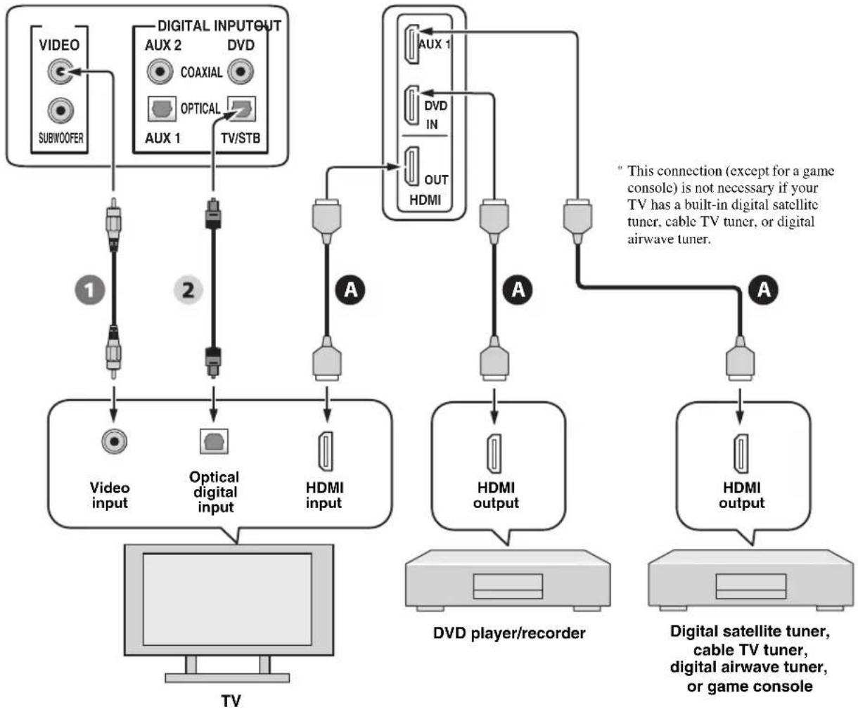
Connections using HDMI cables
This unit is equipped with 2 HDMI input jacks and 1 HDMI output jack. If your TV and other components have HDMI jacks, use HDMI cables for simpler and easier connections, and you can skip the connection procedures from page 22 to 25. If your TV has a built-in digital satellite tuner and an optical digital output jack, connect the optical digital output jack on your TV to the TV/STB OPTICAL DIGITAL INPUT jack on this unit.
Notes
- Even if you connect your TV and this unit via the HDMI jack, you need to connect the video input jack on your TV to the VIDEO OUT jack on this unit in order to display the OSD of this unit.
- When HDMI CONTROL is set to OFF (see page 82) and this unit is in the standby mode, the signals input at the HDMI IN jacks are not output at the HDMI OUT jack.

We recommend that you secure the HDMI cable(s) with adhesive tape, etc. once you have connected the HDMI cable(s) to the HDMI jack(s) of this unit.
Rear panel of this unit
flowchart
graph TD
    A["VIDEO"] --> B["SUBWOOFER"]
    C["DIGITAL INPUT OUT"] --> D["AUX 2"]
    C --> E["DVD"]
    C --> F["AUX 1"]
    C --> G["TV/STB"]
    H["Video input"] --> I["Optical digital input"]
    J["HDMI input"] --> K["Out HDMI"]
    L["DVd player/recorder"] --> M["HDMI output"]
    N["HDMI output"] --> O["HDMI"]
    P["Digital satellite tuner, cable TV tuner, digital airwave tuner, or game console"] --> Q["HDMI output"]
    R["TV"] --> S["TV"]
    T["AUX 1"] --> U["AUX 1"]
    V["DVD IN"] --> W["DVD IN"]
    X["OUT HDMI"] --> Y["OUT HDMI"]
    style A fill:#f9f,stroke:#333
    style C fill:#f9f,stroke:#333
    style H fill:#ccf,stroke:#333
    style N fill:#ccf,stroke:#333
    style L fill:#cfc,stroke:#333
    style P fill:#fcc,stroke:#333
Audio/Video

HDMI cable OSD video pin cable
Video

Audio

Optical cable
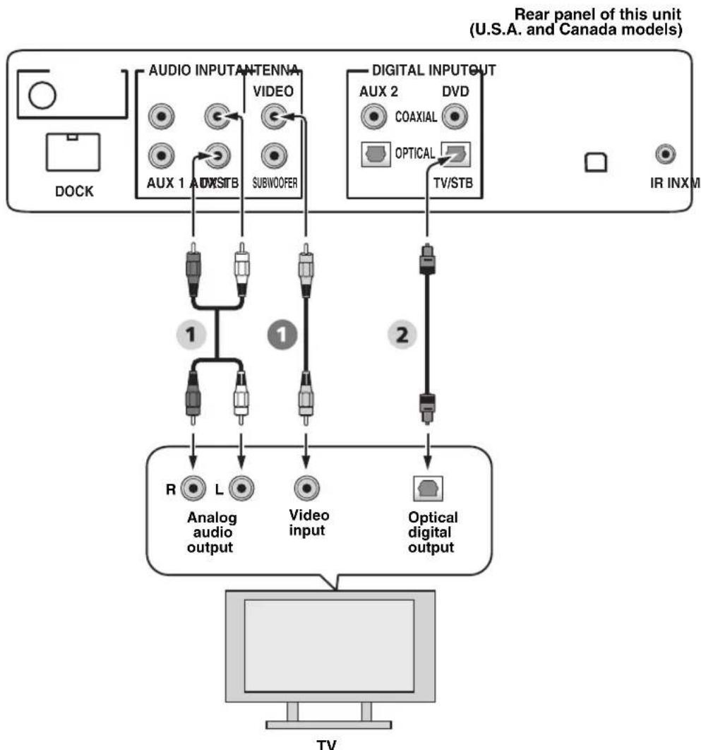
Connecting a TV
For audio connection, connect the analog audio output jacks on your TV to the TV/STB AUDIO INPUT jacks on this unit. If your TV has an optical digital output jack, connect the optical digital output jack on your TV to the TV/STB OPTICAL DIGITAL INPUT jack on this unit.
For video connection, connect the video input jack on your TV to the VIDEO OUT jack on this unit to display the OSD for easy viewing when you adjust the system parameters in SET MENU.

To prevent the optical cable from being unplugged, affix the optical cable in the supplied cable clamp (see page 20).
Notes
- If you make analog and optical digital audio connections at the same time as shown in the illustration below, the digital audio signals input at the TV/STB OPTICAL DIGITAL INPUT jack take priority over the analog audio signals input at the TV/STB AUDIO INPUT jacks.
- Even if you connect your TV and this unit via the HDMI jack, you need to connect the video input jack on your TV to the VIDEO OUT jack on this unit in order to display the OSD of this unit.
flowchart
graph TD
    A["DOCK"] --> B["AUDIO INPUT ANTENNA"]
    B --> C["AUX 1"]
    B --> D["AUX STB"]
    B --> E["VIDEO"]
    B --> F["SUBWOOFER"]
    G["DIGITAL INPUT OUT"] --> H["AUX 2"]
    G --> I["DVD"]
    G --> J["COAXIAL"]
    G --> K["OPTICAL"]
    G --> L["TV/STB"]
    M["IR INXM"] --> N["TV"]
    B --> O["1"]
    O --> P["R Analog audio output"]
    O --> Q["L Video input"]
    O --> R["Optical digital output"]
    P --> S["2"]
    Q --> S
    R --> S
Video Audio

OSD video pin cable Audio pin cable

Optical cable
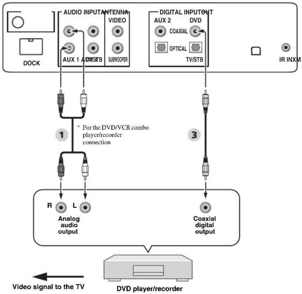
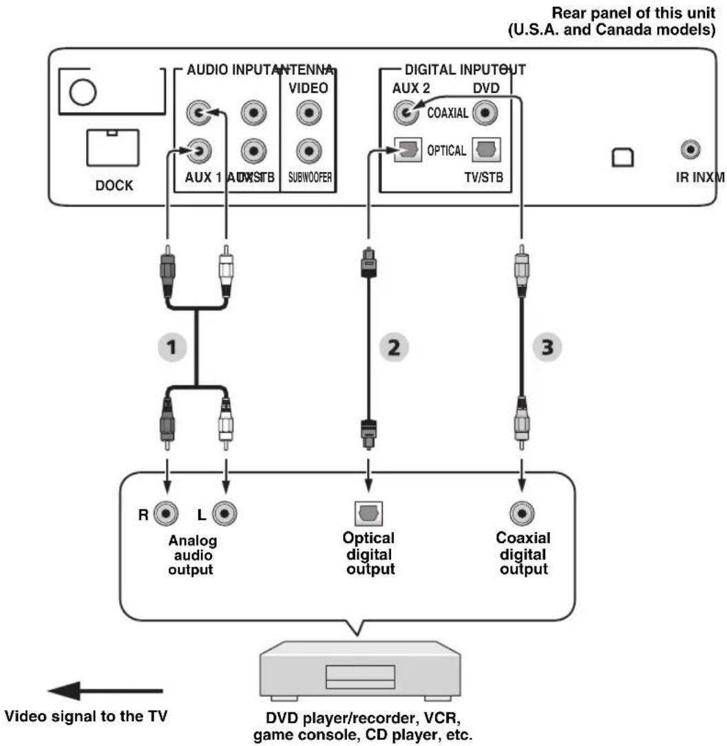
Connecting a DVD player/recorder
Connect the coaxial digital output jack on your DVD player/recorder to the DVD COAXIAL DIGITAL INPUT jack on this unit. When you connect this unit to your DVD/VCR combo player/recorder, connect the analog audio output jacks on your DVD/VCR combo player/recorder to the AUX 1 AUDIO INPUT jacks on this unit in addition to the coaxial digital audio connection.

To prevent the optical cable from being unplugged, affix the optical cable in the supplied cable clamp (see page 20).
Notes
- Check that your DVD player/recorder is properly set to output Dolby Digital and DTS digital audio signals. If not, adjust the system settings of your DVD player/recorder. For details, refer to the operation manual supplied with your DVD player/recorder.
- If your DVD player/recorder does not have a coaxial digital output jack, make an optical digital audio connection instead (see page 27).
Rear panel of this unit (U.S.A. and Canada models)
flowchart
graph TD
    A["DOCK"] --> B["AUX 1 AUXSTB"]
    B --> C["VIDEO SUBWOOFER"]
    D["AR INXM"] --> E["TV/STB"]
    E --> F["DVD player/recorder"]
    G["1"] --> H["R Analog audio output"]
    I["2"] --> J["L Analog audio output"]
    K["3"] --> L["Coaxial digital output"]
    M["1"] --> N["For the DVD/VCR combo player/recorder connection"]
    O["3"] --> P["Coaxial digital output"]
    Q["Video signal to the TV"] --> R["DVD player/recorder"]
Audio
1 Audio pin cable
3 Digital audio pin cable
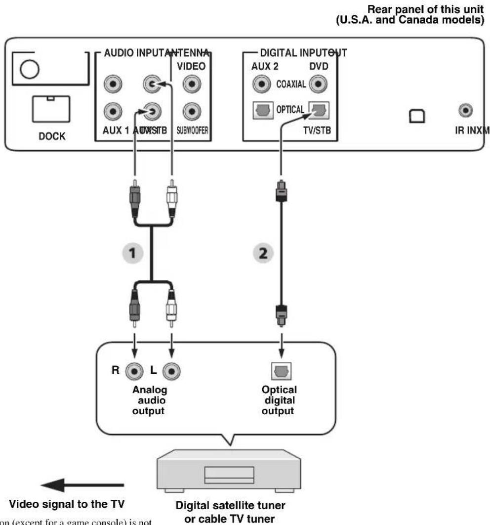
Connecting a digital satellite tuner or a cable TV tuner
Connect the optical digital output jack on your digital satellite tuner or cable TV tuner to the TV/STB OPTICAL DIGITAL INPUT jack on this unit. Connect the analog audio output jacks on your digital satellite tuner or cable TV tuner to the TV/STB AUDIO INPUT jacks on this unit.

To prevent the optical cable from being unplugged, affix the optical cable in the supplied cable clamp (see page 20).
flowchart
graph TD
    A["DOCK"] --> B["AUDIO INPUT ANTENNA VIDEO AUX 1 AUTO STB SUBWOOFER"]
    C["IR INXM"] --> D["DIGITAL INPUT OUT AUX 2 DVD COAXIAL OPTICAL TV/STB"]
    B --> E["1"]
    D --> F["2"]
    E --> G["R Analog audio output"]
    F --> H["Optical digital output"]
    G --> I["Video signal to the TV"]
    H --> J["Digital satellite tuner or cable TV tuner"]
    style A fill:#f9f,stroke:#333
    style C fill:#f9f,stroke:#333
    style I fill:#ccf,stroke:#333
    style J fill:#ccf,stroke:#333
* This connection (except for a game console) is not necessary if your TV has a built-in digital satellite tuner, cable TV tuner, or digital airwave tuner.
Audio
1 Audio pin cable
2 Optical cable
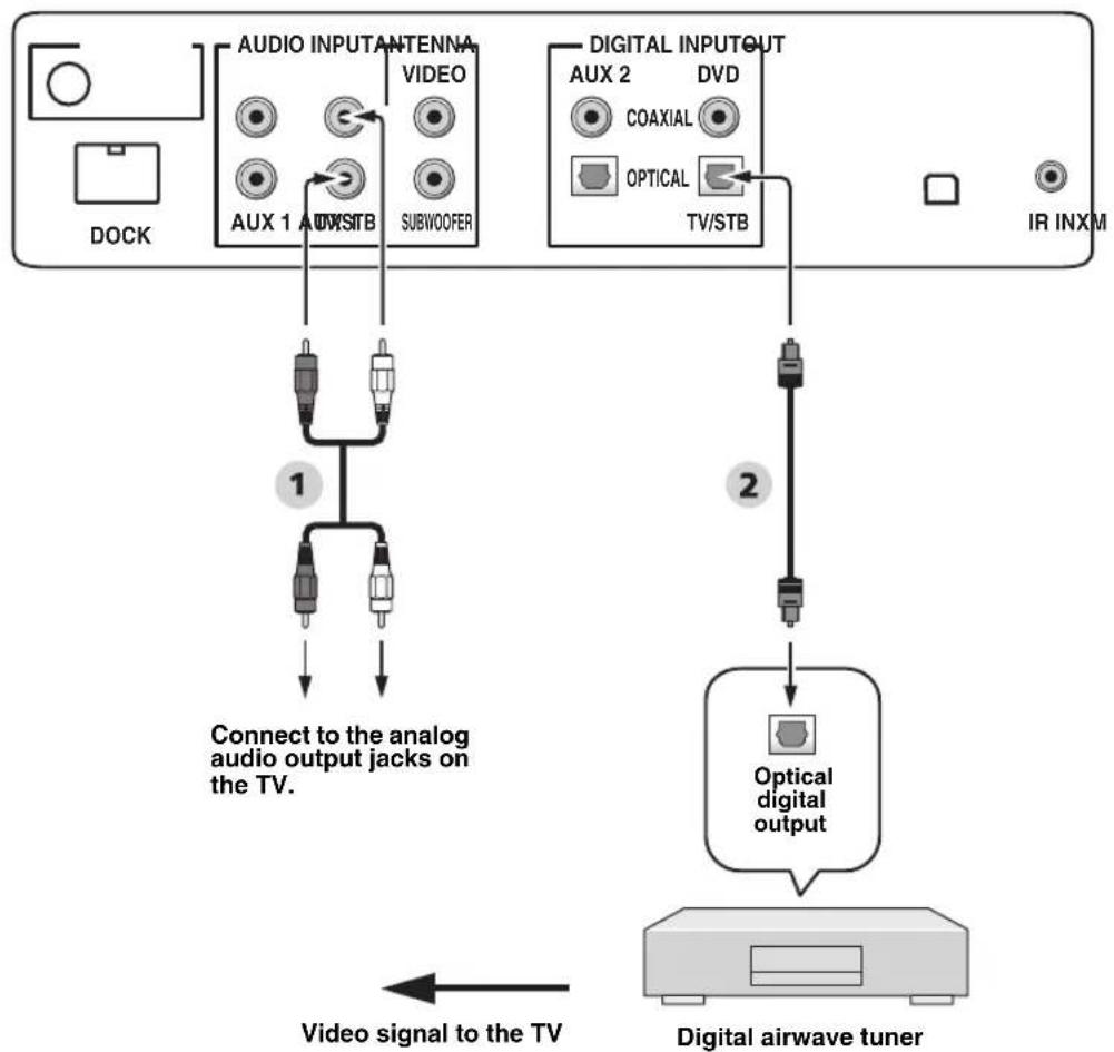
Connecting a digital airwave tuner
Connect the TV/STB AUDIO INPUT jacks on this unit to the analog audio output jacks on your TV. Connect the optical digital output jack on your digital airwave tuner to the TV/STB OPTICAL DIGITAL INPUT jack on this unit in addition to the analog audio connection. By doing so, you can enjoy both analog and digital broadcasts.

To prevent the optical cable from being unplugged, affix the optical cable in the supplied cable clamp (see page 20).
Rear panel of this unit (U.S.A. and Canada models)
flowchart
graph TD
    A["DOCK"] --> B["AUDIO INPUT ANTENNA VIDEO AUX 1 AUX STB SUBWOOFER"]
    B --> C["Connect to the analog audio output jacks on the TV."]
    D["IR INXM"] --> E["DIGITAL INPUT OUT AUX 2 DVD COAXIAL OPTICAL TV/STB"]
    E --> F["Optical digital output"]
    F --> G["Video signal to the TV"]
    G --> H["Digital airwave tuner"]
* This connection (except for a game console) is not necessary if your TV has a built-in digital satellite tuner, cable TV tuner, or digital airwave tuner.
Audio
1 Audio pin cable
2 Optical cable
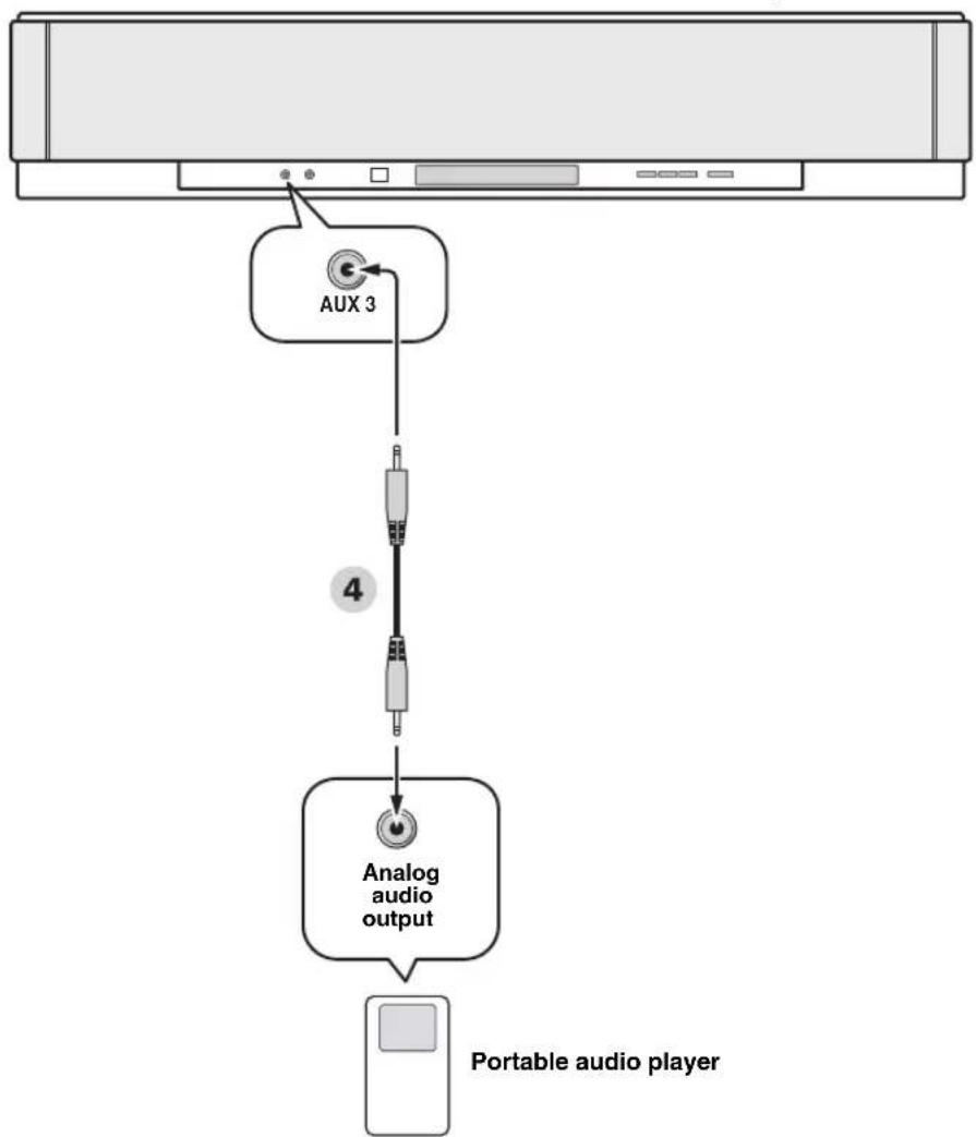
Connecting a portable audio player
Connect the analog audio output jack on your portable audio player to the AUX 3 input jack on the front panel of this unit.
Front panel of this unit
flowchart
graph TD
    A["Portable audio player"] --> B["Analog audio output"]
    B --> C["AUX 3"]
    C --> D["4"]
Audio
Connecting other external components
If your component supports optical digital connections, connect the optical digital output jack on your component (e.g., DVD player/recorder) to the AUX 1 OPTICAL DIGITAL INPUT jack on this unit. If your component does not support optical digital connections, connect the coaxial digital output jack on your component to the AUX 2 COAXIAL DIGITAL INPUT jack on this unit.
If your component does not support any digital connections, connect the analog audio output jacks on your component (e.g., VCR) to the AUX 1 AUDIO INPUT jacks on this unit.
#
To prevent the optical cable from being unplugged, affix the optical cable in the supplied cable clamp (see page 20).
Note
If you make analog and digital audio connections at the same time as shown in the illustration below, the digital audio signals input at the AUX 1 OPTICAL DIGITAL INPUT or AUX 2 COAXIAL DIGITAL INPUT jack take priority over the analog audio signals input at the AUX 1 AUDIO INPUT jacks.
flowchart
graph TD
    A["David player/recorder, VCR, game console, CD player, etc."] --> B["Video signal to the TV"]
    B --> C["Analog audio output"]
    B --> D["Optical digital output"]
    B --> E["Coaxial digital output"]
    C --> F["1"]
    D --> G["2"]
    E --> H["3"]
    F --> I["AUX 1"]
    F --> J["AUX STB"]
    F --> K["SUBWOOFER"]
    G --> L["DIV"]
    H --> M["DVD"]
    N["AR INXM"] --> O["IR INXM"]
    P["DOCK"] --> Q["AUDIO INPUT ANTENNA VIDEO"]
    R["TV/STB"] --> S["DIGITAL INPUT OUT AUX 2"]
    T["COAXIAL"] --> U["OPTICAL"]
    V["1"] --> W["R Analog audio output"]
    V --> X["L Optical digital output"]
    V --> Y["3"]
Audio
1 Audio pin cable
2 Optical cable
3 Digital audio pin cable
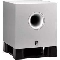
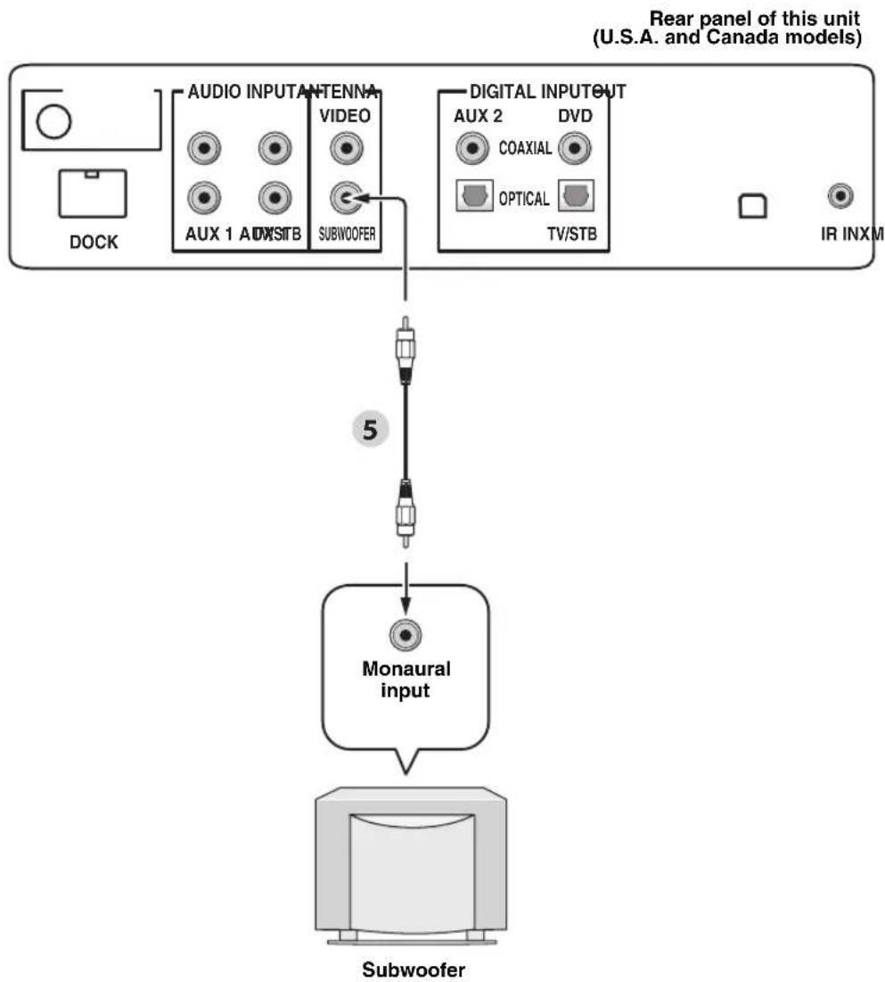
Connecting a subwoofer
Connect the monaural input jack on your subwoofer to the SUBWOOFER OUT jack on this unit.
This connection alone does not output sound from the connected subwoofer. To output sound from the connected subwoofer, turn on the power of your subwoofer and then run AUTO SETUP (see page 35) or select SWFR for BASS OUT in SUBWOOFER SET (see page 78).
flowchart
graph TD
    A["DOCK"] --> B["AUDIO INPUT ANTENNA VIDEO"]
    B --> C["SUBWOOFER"]
    D["ARX 1 ADWSTB"] --> E["VIDEO"]
    F["IR INXM"] --> G["TV/STB"]
    H["Monaural input"] --> I["Subwoofer"]
    style A fill:#f9f,stroke:#333
    style D fill:#f9f,stroke:#333
    style F fill:#f9f,stroke:#333
    style H fill:#ccf,stroke:#333
    style I fill:#cfc,stroke:#333
Audio
5 Subwoofer pin cable
Connecting the FM antenna
Connect the supplied FM antenna to the FM ANTENNA jack on this unit.

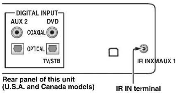
About the IR IN terminal (U.S.A. and Canada models only)
The IR IN terminal does not support normal external component connection. This is a control expansion terminal for commercial use only.
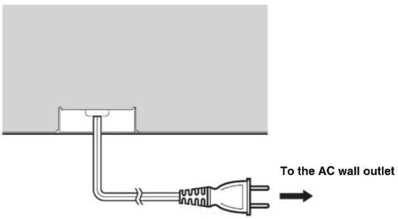
Connecting the AC power supply cable
Once all other connections are complete, plug the AC power supply cable into the AC wall outlet.
Getting started
Installing batteries in the remote control
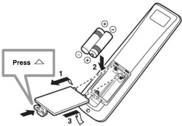
1 Press and hold the mark on the battery cover and then open the cover.
2 Insert the two supplied batteries (AA, R6, UM-3) into the battery compartment.
Make sure you insert the batteries according to the polarity markings (+/-).
3 Close the battery cover.
Notes
- Change all of the batteries if you notice the following conditions: the operation range of the remote control decreases or the transmission indicator does not light up or becomes dim.
- Do not use old batteries together with new ones.
- Do not use different types of batteries (such as alkaline and manganese batteries) together. Read the packaging carefully as these different types of batteries may have the same shape and color.
- Exhausted batteries may leak. If the batteries have leaked, dispose of them immediately. Avoid touching the leaked material or letting it come into contact with clothing, etc. Clean the battery compartment thoroughly before installing new batteries.
- Do not throw away batteries with general house waste. Dispose of them correctly in accordance with your local regulations.
- The memory stored in the remote control may be erased in the following cases:
- The remote control is left without batteries for more than two minutes.
- Exhausted batteries remain in the remote control.
- The buttons on the remote control are accidentally pressed when you change batteries.
- If the memory stored in the remote control is unwantedly erased, insert new batteries and set the remote control codes again.

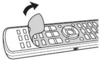
Remove the transparent sheet before using the remote control.
natural_image
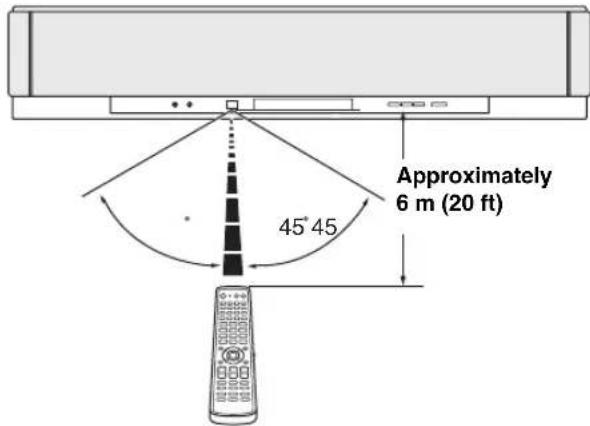
Illustration of a remote control with a mouse and scroll, showing no text or symbolsOperation range of the remote control
The remote control transmits a directional infrared beam. Use the remote control within 6 m (20 ft) of this unit and point it toward the remote control sensor of this unit during operation.
Notes
- Do not spill water or other liquids on the remote control.
- Do not drop the remote control.
- Do not leave or store the remote control in the following places: – places of high humidity, such as near a bath
- places of high temperatures, such as near a heater or a stove
- places of extremely low temperatures
- dusty places
- Do not expose the remote control sensor of this unit to direct sunlight or lighting such as inverted fluorescent lamps.
- If the batteries grow old, the effective operation range of the remote control decreases considerably. If this happens, replace the batteries with two new ones as soon as possible.
Turning on this unit or setting it to the standby mode
(U.S.A. and Canada models)
1 Press STANDBY/ON to turn on the power of this unit.
The volume level appears in the front panel display, and the current input source and beam mode are displayed.
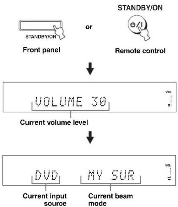
flowchart
graph TD
    A["STANDBY/ON"] --> B["Front panel"]
    C["Remote control"] --> D["VOLUME 30"]
    B --> E["Current volume level"]
    D --> F["VOL"]
    E --> G["DVD"]
    E --> H["MY SUR"]
    G --> I["Current input source"]
    H --> J["Current beam mode"]
2 Press STANDBY/ON again to set this unit to the standby mode.
Note
When this unit is in the standby mode, only STANDBY/ON on the front panel or on the remote control is operational, and the other control buttons on the front panel or on the remote control are not operational until the power of this unit is turned on.
Using SET MENU
Displaying the OSD (on-screen display)
This section describes how to display the OSD (on-screen display) of this unit on your TV screen and to set the parameters for your listening room. Once this is complete, you can enjoy real surround sound while watching TV in the comfort of your own home.
1 Check that the video input jack on your TV is connected to the VIDEO OUT jack on this unit to display the OSD of this unit.
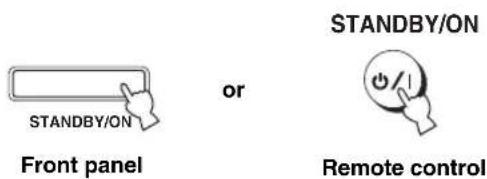
2 Press STANDBY/ON to turn on the power of this unit.

Front panel
or
STANDBY/ON

Remote control
3 Turn on the power of your TV.
The following screen appears on your TV.
HTY-7938
Push [MENU] to begin set-up
OSD screen example
If the OSD does not appear, use the remote control supplied with your TV to switch the video input until the OSD appears.
The flow chart of SET MENU
The following diagram illustrates the overall flow of the setup procedure.
Run LANGUAGE SETUP.
See “Changing OSD language” on page 34.

Run AUTO SETUP (IntelliBeam).
See “AUTO SETUP (IntelliBeam)” on page 35.

natural_image
Simple gray downward arrow symbol on white background (no text or labels)

If an error occurs
Look for a remedy.
See “Error messages for AUTO SETUP” on page 41 for a complete list of error messages and possible remedies.
Play back audio signals or adjust the settings for the beam mode and the CINEMA DSP.
See “Playback” on page 45, “Enjoying surround sound” on page 54, and “Using sound field programs” on page 63.


If you want to make additional settings and adjustments
Run MANUAL SETUP.
See "MANUAL SETUP" on page 72.
#
- If you cannot clearly hear a sound beam from a specific channel, adjust settings for SETTING PARAMETERS (see page 74) or for BEAM ADJUSTMENT (see page 75) in BEAM MENU.
- If there are acoustically absorbent objects such as curtains in the path of the sound beams, adjust settings for TREBLE GAIN in BEAM MENU (see page 77).
Changing OSD language
This feature allows you to select the language of your choice that appears in SET MENU of this unit.
1 Set the operation mode selector to YSP.
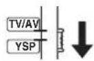
2 Press MENU.
The SET MENU screen appears on your TV.
flowchart
graph LR
    A["MENU"] --> B["SET MENU"]
    B --> C["• MEMORY\n• AUTO SETUP\n• MANUAL SETUP\n• LANGUAGE SETUP\n[▲"]/[▼]:UP/Down\n["ENTER"]:Enter]
-
- The control buttons used for SET MENU are displayed at the bottom of the screen.
- To return to the previous screen while using SET MENU, press RETURN.
• To exit from SET MENU, press MENU once more. - You can also perform the following operations while viewing information in the front panel display.
3 Press /△to select LANGUAGE SETUP, and press ENTER.
The following screen appears on your TV.
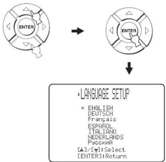
flowchart
graph TD
    A["ENTER"] --> B["ENTER"]
    B --> C["LANGUAGE SETUP"]
    C --> D["• ENGLISH DEUTSCH FRANÇAIS ESPAÑOL ITALIANO NEDERLANDS РУСКИЙ [▲"]/[▼]:Select["ENTER"]:Return]
4 Press / to select the desired language, and press ENTER.
flowchart
graph TD
    A["ENTER"] --> B["→"]
    B --> C["ENTER"]
Choices: ENGLISH (English), DEUTSCH (German), Français (French), ESPAÑOL (Spanish), ITALIANO (Italian), NEDERLANDS (Dutch), Русский (Russian)
AUTO SETUP (IntelliBeam)
This unit creates a sound field by reflecting sound beams on the walls of your listening room and by broadening the cohesion of all the channels. Just as you would arrange the speaker position of other audio systems, you need to set the beam angle to enjoy the best possible sound from this unit.
This unit employs the beam optimization and sound optimization features with the aid of the supplied IntelliBeam microphone, allowing you to avoid troublesome listening-based setup and achieving highly accurate sound adjustments that best match your listening environment. We call these two features “IntelliBeam” generically.
Beam optimization:
This feature optimizes the beam angle so that the parameter best matches your listening environment.
Sound optimization:
This feature optimizes the beam delay, volume, and quality so that the parameters best match your listening environment.
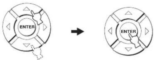
The flow chart of AUTO SETUP
This unit performs a series of checks to optimize the beam angle, delay, volume, and quality. You can choose to optimize all or part of the parameters.
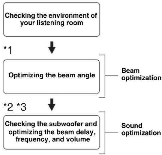
flowchart
graph TD
    A["Checking the environment of your listening room"] -->|*1| B["Optimizing the beam angle"]
    B --> C["Beam optimization"]
    B -->|*2 *3| D["Checking the subwoofer and optimizing the beam delay, frequency, and volume"]
    D --> E["Sound optimization"]
Notes
*1 The beam angle checking procedure is skipped if SOUND OPTIMZ only is selected.
*2 The sound optimization procedure is skipped if BEAM OPTIMZ only is selected.
*3 The subwoofer checking procedure is skipped if BEAM OPTIMZ only is selected.
Installing the IntelliBeam microphone
The supplied IntelliBeam microphone collects and analyzes the sound that this unit produces in your actual listening environment. Follow the procedure below to connect the IntelliBeam microphone to this unit and make sure that the IntelliBeam microphone is placed in a proper location and that there are no large obstacles between the IntelliBeam microphone and the walls in your listening room.
Notes
- After you have completed the AUTO SETUP procedure, be sure to disconnect the IntelliBeam microphone.
- The IntelliBeam microphone is sensitive to heat.
- Keep it away from direct sunlight.
Do not place it on top of this unit.
- Do not connect the IntelliBeam microphone to an extension cable as doing so may result in an inaccurate sound optimization.
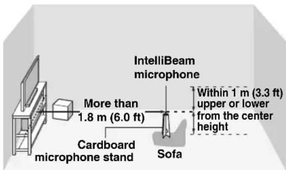
- An error may occur during the AUTO SETUP procedure if the IntelliBeam microphone is not properly placed in your listening room. To avoid the possibility of an error:
- Do not place the IntelliBeam microphone to the extreme right or left from the center of this unit.
- Do not place the IntelliBeam microphone within 1.8m (6.0 ft) from the front of this unit.
-
Do not place the IntelliBeam microphone more than 1m (3.3 ft) upper or lower from the center height of this unit.
-
Make sure that there are no obstacles between the IntelliBeam microphone and the walls in your listening room as these objects obstruct the path of sound beams. However, any objects that are in contact with the walls will be regarded as a protruding part of the walls.
- The best possible results are achieved if the IntelliBeam microphone is placed at the same height as your ears would be when you are seated in your listening position. However, if this is not possible, you can manually fine-tune the sound beam angle and balance the sound beam output levels using MANUAL SETUP (see page 72) once the AUTO SETUP procedure is completed.
- If a subwoofer with adjustable volume and crossover/high-cut frequency controls is connected to this unit, set the volume between 10 and 12 o'clock as viewed on a conventional clockface and set the crossover/high-cut frequency to the maximum.


Subwoofer
1 Press STANDBY/ON to turn off the power of this unit.

Front panel
or
STANDBY/ON

Remote control
2 Connect the supplied IntelliBeam microphone to the INTELLIBEAM MIC jack on the front panel.
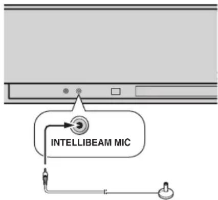
3 Place the IntelliBeam microphone on a flat level surface more than 1.8 m (6.0 ft) from the front of the unit and within 1 m (3.3 ft) upper or lower from the center height of the unit with the IntelliBeam microphone facing upward at your normal listening position.
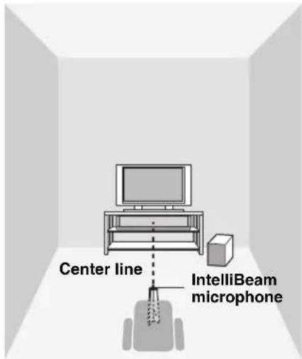
Note
Be sure to place the IntelliBeam microphone on an imaginary center line drawn from this unit.
#
You may want to use the supplied cardboard microphone stand to affix the IntelliBeam microphone at the same height as your ears would be when you are seated in your listening position.
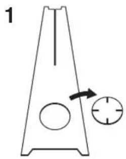
■ Assembling the supplied cardboard microphone stand
You will find three separate parts (one circular part and two longitudinal parts) of the cardboard microphone stand originally put together.
natural_image
Simple line drawing of a triangular container with a circular opening and an arrow pointing to a circular cross-section (no text or symbols)
natural_image
Technical line drawing of a mechanical part with an arrow indicating direction (no text or symbols)
1 Disassemble the three parts of the cardboard microphone stand originally put together.
2 Insert one of the longitudinal part into the crevice of the other longitudinal part.
3 Place the circular part on top of the two combined longitudinal parts.
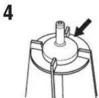
4 Place the supplied IntelliBeam microphone on top of the circular part.
Using AUTO SETUP (IntelliBeam)
Once the IntelliBeam microphone is firmly connected to this unit and properly placed in your listening room, follow the procedure below to start the AUTO SETUP procedure.
You can also enter the AUTO SETUP procedure simply by pressing and holding AUTO SETUP for more than two seconds. In this case, this unit performs both of the beam optimization and sound optimization procedures.
(U.S.A. and Canada models)
Notes
- Make sure that your listening room is as quiet as possible while this unit is performing the AUTO SETUP procedure.
- To achieve the best results possible, evacuate yourself from your listening room until the AUTO SETUP procedure is completed so that you may not obstruct the path of sound beams.
- Be advised that it is normal for loud test tones to be output during the AUTO SETUP procedure.
- The AUTO SETUP procedure may not be run successfully if this unit is installed in one of the rooms described in "Before installing this unit" on page 16. In such cases, run MANUAL SETUP (see page 72) to manually adjust the corresponding parameters.
- If an error occurs, an error buzzer is played, the AUTO SETUP procedure stops, and an error message appears on the screen. See “Error messages for AUTO SETUP” on page 41 for appropriate remedies.

- The AUTO SETUP procedure takes about three minutes maximum. A chime is played when the AUTO SETUP procedure is run successfully.
-
If there are curtains in your listening room, we recommend following the procedure below.
-
Open the curtains to improve sound reflection.
- Run BEAM OPTIMZ only.
- Close the curtains.
- Run SOUND OPTIMZ only.
- You can save the settings optimized by the AUTO SETUP procedure (see page 42). A set of settings optimized according to the specific conditions of your listening environment can be recalled later depending on the varying conditions of your listening environment (see page 43).
1 Press STANDBY/ON to turn on the power of this unit.
If a subwoofer is connected to this unit, turn on the power of the subwoofer.
2 Set the operation mode selector to YSP.
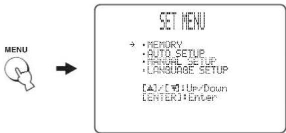
3 Press MENU.
The SET MENU screen appears on your TV.
![MENU SET MENU →: MEMORY • AUTO SETUP • MANUAL SETUP • LANGUAGE SETUP [▲]/[▼]:Up/Down [ENTER]:Enter](/content/2026/02/375754/images/da0163af2de80b7081f36262d201d6d94d9adb9782dd046f7e3f1a26ae25e4b0.jpg)
[Non-Text]
- The control buttons used for SET MENU are displayed at the bottom of the screen.
- To return to the previous screen while using SET MENU, press RETURN.
- To exit from the SET MENU screen, press MENU again.
- You can start the BEAM+SOUND OPTIMZ procedure simply by pressing and holding AUTO SETUP for more than two seconds. Steps 4 and 5 are skipped and then the screen shown in step 5 is displayed on your TV. Start the AUTO SETUP procedure from step 6.
- You can also perform the following operations in the front panel display.
4 Press / △ to select AUTO SETUP and press ENTER.
The following screen appears on your TV.
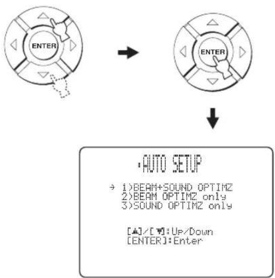
flowchart
graph TD
    A["ENTER"] --> B["ENTER"]
    B --> C["• AUTO SETUP\n→ 1)BEAM+ SOUND OPTIMZ\n2)BEAM OPTIMZ only\n3)SOUND OPTIMZ only\n[▲"]/[▼]:Up/Down\n["ENTER"]:Enter]
5 Press / to select BEAM+SOUND OPTIMZ, BEAM OPTIMZ only, or SOUND OPTIMZ only and then press ENTER.
The following screen appears on your TV.
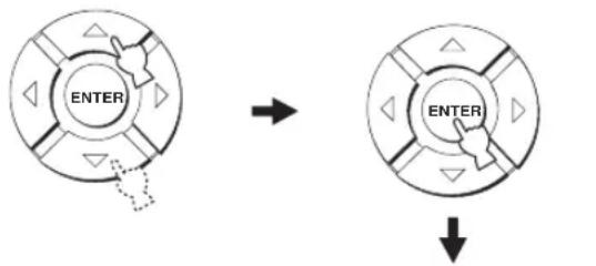
flowchart
graph TD
    A["ENTER"] --> B["Arrow"]
    B --> C["ENTER"]
    C --> D["Arrow"]

PREPARATION & CHECK Please connect the MIC. Please place the MIC at least 1.8m/6ft away from the YSP unit. The MIC should be set at ear level when seated. Measurement takes about 3min. After ENTERJ is pressed, please leave the room. ENTER:Start RETURN:Cancel
BEAM+SOUND OPTIMZ
(Beam optimization and sound optimization)
Use to optimize the beam angle, delay, volume, and quality so that the parameters best match your listening environment.
It is recommended that you should select this optimization feature in the following cases:
- If you make settings for the first time.
- If the unit has been relocated.
- If your listening room has been restructured.
- If the objects in your listening room (furniture, etc.) have been rearranged.
This menu takes about three minutes.
BEAM OPTIMZ only
(Beam optimization only)
Use to optimize the beam angle so that the parameter best matches your listening environment.
This menu takes about one minute.
SOUND OPTIMZ only
(Sound optimization only)
Use to optimize the beam delay, volume, and quality so that the parameters best match your listening environment. It is recommended that you should select this optimization feature in the following cases:
- If you have opened or closed the curtains in your listening room before using this unit.
- If you have manually set the beam angle.
This menu takes about two minutes.
Note
You must optimize the beam angle in the BEAM OPTIMZ only procedure before starting the SOUND OPTIMZ only procedure.
6 Check the following points once again before starting the AUTO SETUP procedure.
- Is the IntelliBeam microphone firmly connected to this unit?
- Is the IntelliBeam microphone placed in a proper location?
- Are there any large obstacles in between the IntelliBeam microphone and the walls in your listening room?
7 Press ENTER to start the AUTO SETUP procedure.
The following screen appears on your TV and the AUTO SETUP procedure starts in 10 seconds.
Leave the room quietly before starting the AUTO SETUP procedure.


AUTO SETUP START
Will begin in 10sec Please leave the room
Flashes
If an error occurs, an error buzzer is played and an error message is displayed. See “Error messages for AUTO SETUP” on page 41 for a complete list of error messages and their proper remedies. Follow the instructions and perform the AUTO SETUP procedure again.
8 Check that the following screen is displayed on your TV.
The results of the AUTO SETUP procedure are displayed on your TV.
Example 1
![SHORESULT MEASUREMENTCOMPLETE BEOMMODE:5BEAM SUBWOOPER:NOTAPPLICABLE [ENTER]:Saveset-up. [RETURN]:Donotsaveset-up.](/content/2026/02/375754/images/d3b56c02947bcfadd0db04018ef7d2c68b39dd4efb40e68b08ef260c1c846d9a.jpg)
Example 2
![SHAREULT MEASUREMENTCOMPLETE ENVIRONMENTCHECK[FAILED] BEAMMODE:SBEAM SUBWOOFER:YES [ENTER]:Saveset-up. [RETURN]:Donotsaveset-up.](/content/2026/02/375754/images/63201ca02a94ee0dbda68680a11605597c775026b50efa0b7a4eddff3bcf16cc.jpg)
[Non-Text]
- If "ENVIRONMENT CHECK [FAILED]" is displayed, we recommend running the AUTO SETUP procedure again. For details, see step 9.
- If "SUBWOOFER: NOT APPLICABLE" is displayed even though a subwoofer is connected to this unit, increase the volume level of the subwoofer and run the AUTO SETUP procedure again.
- Depending on the environment of your listening room, the beam angle of front left and right, and surround left and right may be set to the same value even if "5 BEAM" is displayed as a result.
9 Press ENTER to confirm the results or press RETURN to cancel the results.
The following screen is displayed for two seconds and then disappears from your TV.
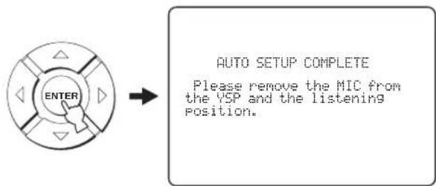
If "ENVIRONMENT CHECK [FAILED]" is displayed in step 8, the following screen is displayed after pressing ENTER. In this case, see ERROR E-1 in "Error messages for AUTO SETUP" on page 41. Press ENTER to exit AUTO SETUP and then run the procedure again from step 3.
![AUTO SETUP COMPLETE Your YSP unit may not be set up correctly. We recommend you try again. Please press [ENTER] key to exit.](/content/2026/02/375754/images/966093211ecde237f1e971eec46d78f337e46be5370925a19cf48783ae221535.jpg)
10 Disconnect the IntelliBeam microphone from the INTELLIBEAM MIC jack on the front panel.
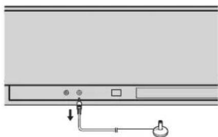
natural_image
Diagram of a device panel with ports and a hanging knob (no text or symbols)
If you want to save and load settings, see "Using the system memory" on page 42.
■ Error messages for AUTO SETUP
Before the AUTO SETUP procedure starts
| Error message Cause Remedy | See page | ||
| ERROR E-2No MIC detected. Please checkMIC connection and re-try. | The IntelliBeam microphone is not connected to this unit. | Connect the IntelliBeam microphone to this unit. | 36 |
While the AUTO SETUP procedure is in progress
If one of the errors listed below except E-1 is displayed, press RETURN. In case you have started the AUTO SETUP procedure by pressing AUTO SETUP in step 3, run the procedure again from step 3 after the screen disappears. In case you have started the AUTO SETUP procedure by pressing MENU in step 3, run the procedure again from step 4 after the screen in step 3 is displayed. Run MANUAL SETUP if the problem is difficult to be saved.
| Error message Cause Remedy | See page | ||
| ERROR E-1Please test in quieter environment. | There is too much unwanted noise in your listening room. | Make sure that your listening room is as quiet as possible. You may want to choose certain hours during the day when there is not much noise coming from outside. | — |
| ERROR E-2No MIC detected. Please check MIC connection and re-try. | The IntelliBeam microphone was disconnected while the AUTO SETUP procedure was in progress. | Make sure that the IntelliBeam microphone is firmly connected to this unit. | 36 |
| ERROR E-3Unexpected control is detected.Please re-try. | Some other operations were performed on this unit while the AUTO SETUP procedure was in progress. | Do not perform any other operations while the AUTO SETUP procedure is in progress. | — |
| ERROR E-4Please check MIC position. MIC should be set in front of YSP. | The IntelliBeam microphone is not placed in front of this unit. | Make sure that the IntelliBeam microphone is installed in front of this unit. | 36 |
| ERROR E-5Please check MIC position. MIC should be set above 1.8m/6.0ft. | The IntelliBeam microphone is not placed in the right distance from this unit. | Make sure that the IntelliBeam microphone is installed more than 1.8 m (6.0 ft) from the front of this unit and within 1 m (3.3 ft) from the center height of this unit. | 36 |
| ERROR E-6Volume level is lower than expected. Please check MIC position/connection and re-try. | The IntelliBeam microphone cannot collect the sound produced by this unit because the sound output level is too low. | Make sure that the IntelliBeam microphone is firmly connected to this unit and placed in a proper location. If the problem persists, contact the nearest authorized Yamaha service center for assistance. | 36 |
| ERROR E-7Unexpected error happened.Please re-try. | An internal system error occurred. Repeat the AUTO SETUP procedure. | — | |
Using the system memory
Convenient usage of the system memory
You can save the current settings adjusted in SET MENU in the system memory of this unit. It is handy to save certain settings according to the varying conditions of your listening environment. For example, if there are curtains in the path of sound beams, the effectiveness of the sound beams will vary depending on whether the curtains are open or closed.
When the curtains are open
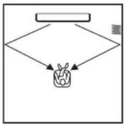
flowchart
graph TD
    A[" "] --> B{ }
    B --> C["F"]
    C --> D["M"]
When the curtains are closed
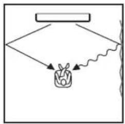
flowchart
graph TD
    A["Rectangular Box"] --> B{Wavy Line}
    B --> C["Plant"]
    C --> D["Arrow 1"]
    C --> E["Arrow 2"]
Saving settings
1 Set the operation mode selector to YSP.
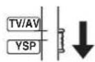
2 Press MENU.
The SET MENU screen appears on your TV.
![MENU SET MENU → · MEMORY · AUTO SETUP · MANUAL SETUP · LANGUAGE SETUP [+]/[+] : Up / Down [ENTER] : Enter](/content/2026/02/375754/images/34e4ccd19f513e996a7f241c4d29f4645155b8bf133144bf872f4759b42cf232.jpg)
[Non-Text]
- The control buttons used for SET MENU are displayed at the bottom of the screen.
- To return to the previous screen while using SET MENU, press RETURN.
- To exit from the SET MENU screen, press MENU once more.
- You can also perform the following operations in the front panel display.
3 Press / to select MEMORY and press ENTER.
The following screen appears on your TV.
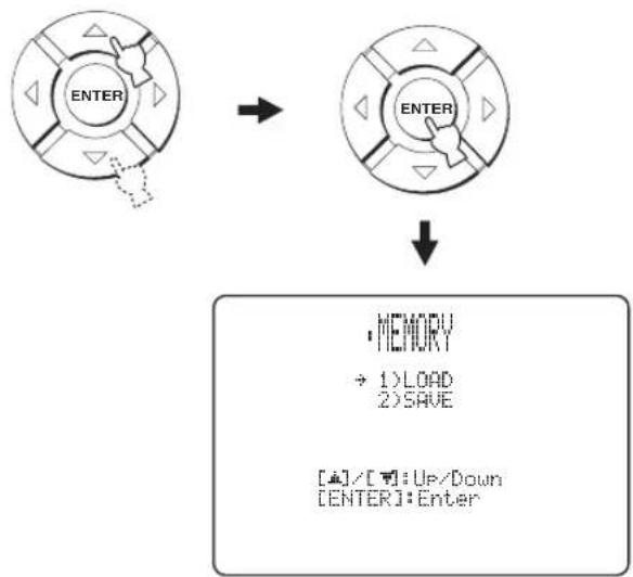
flowchart
graph TD
    A["ENTER"] --> B["ENTER"]
    B --> C["MEMORY<br>→ 1)LOAD<br>2)SAVE<br>[▲"]/[▼]:Up/Down
[ENTER]:Enter]
4 Press / △ to select SAVE and press ENTER.
The following screen appears on your TV.
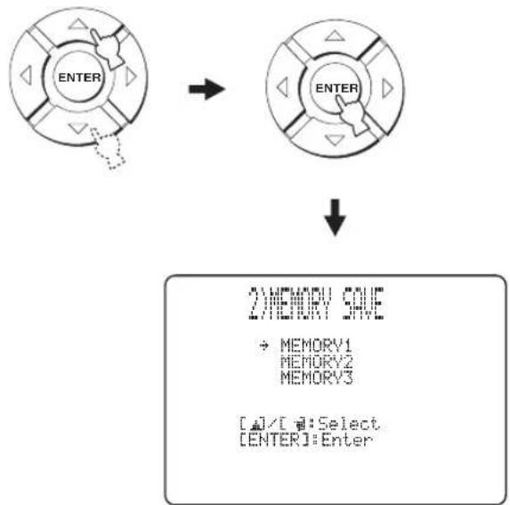
flowchart
graph TD
    A["ENTER"] --> B["ENTER"]
    B --> C["2) MEMORY SAVE\n→ MEMORY1\nMEMORY2\nMEMORY3\n[□"]/[□]:Select\n["ENTER"]:Enter]
5 Press /△to select MEMORY1, MEMORY2, or MEMORY3 and press ENTER. The following screen appears on your TV.
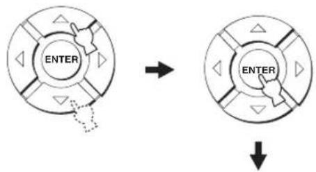
flowchart
graph TD
    A["ENTER"] --> B["Arrow"]
    B --> C["ENTER"]
    C --> D["Down Arrow"]
2024年1月1日
MEMORY1 Save Now?
Push ENTER to Save
6 Press ENTER again.
The new parameters are saved as MEMORY1, MEMORY2, or MEMORY3. Once the parameters are saved, the display returns to the SET MENU screen.
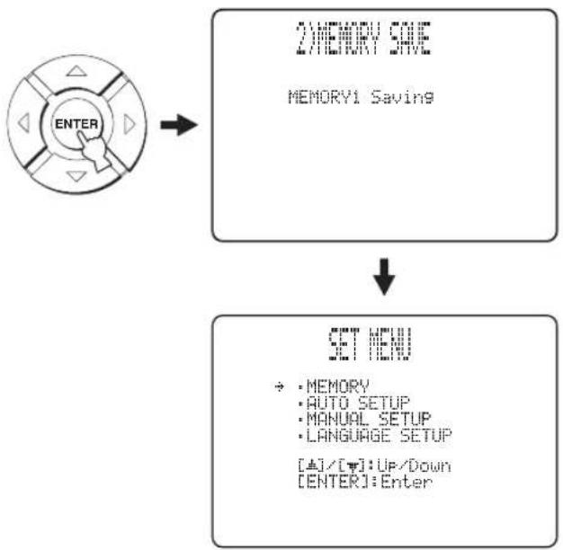
flowchart
graph TD
    A["ENTER"] --> B["2) MEMORY SAVE\nMEMORY1 Saving"]
    B --> C["SET MENU\n• MEMORY\n• AUTO SETUP\n• MANUAL SETUP\n• LANGUAGE SETUP\n[±"]/[×]: Up/Down\n["ENTER"]: Enter]
7 Press MENU to exit.
The SET MENU screen disappears from your TV.

Loading settings
You can recall the settings saved in "Saving settings" on page 42 according to the varying conditions of your listening environment.
1 Set the operation mode selector to YSP.
2 Press MENU.
The SET MENU screen appears on your TV.
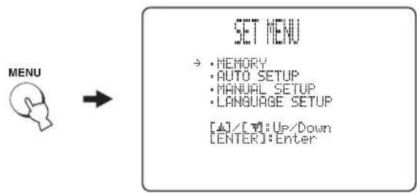
flowchart
graph LR
    A["MENU"] --> B["SET MENU"]
    B --> C["→: MEMORY\n→: AUTO SETUP\n→: MANUAL SETUP\n→: LANGUAGE SETUP\n[4"]/[3]:Up/Down\n["ENTER"]:Enter]
#
- The control buttons used for SET MENU are displayed at the bottom of the screen.
- To return to the previous screen while using SET MENU, press RETURN.
- To exit from the SET MENU screen, press MENU once more.
- You can also perform the following operations in the front panel display.
3 Press / to select MEMORY and press ENTER.
The following screen appears on your TV.
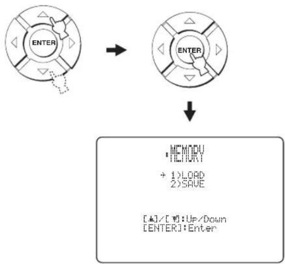
flowchart
graph TD
    A["ENTER"] --> B["ENTER"]
    B --> C[""MEMORY\n+ 1) LOAD\n2) SAVE\n[4"]/[7]: UP/Down\n["ENTER"]: Enter"]
4 Press / to select LOAD and press ENTER.
The following screen appears on your TV.
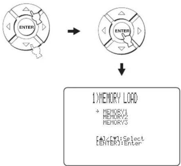
flowchart
graph TD
    A["ENTER"] --> B["ENTER"]
    B --> C["1) MEMORY LOAD\n→ MEMORY1\nMEMORY2\nMEMORY3\n[+"]/[T]:Select\n["ENTER"]:Enter]
5 Press /△to select MEMORY1, MEMORY2, or MEMORY3 and press ENTER.
The following screen appears on your TV.
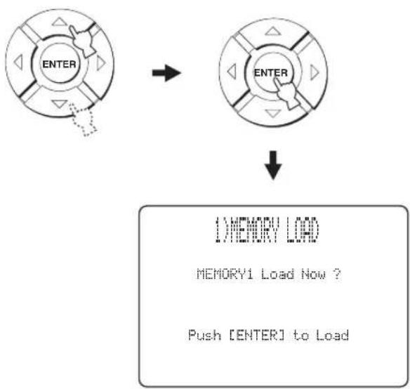
flowchart
graph TD
    A["ENTER"] --> B["ENTER"]
    B --> C["↓ MEMORY LOAD\nMEMORY1 Load Now ?\nPush [ENTER"] to Load]
6 Press ENTER again.
The new parameters saved as MEMORY1, MEMORY2, or MEMORY3 are loaded. Once the parameters are loaded, the display returns to the SET MENU screen.
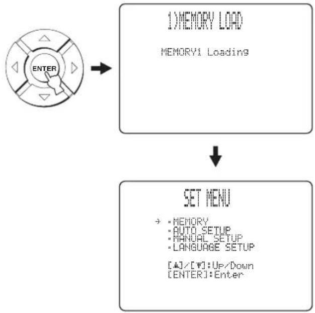
flowchart
graph TD
    A["ENTER"] --> B["1) MEMORY LOAD\nMEMORY1 Loading"]
    B --> C["SET MENU\n→: MEMORY\n→: AUTO SETUP\n→: MANUAL SETUP\n→: LANGUAGE SETUP\n[+"]/[W]:Up/Down\n["ENTER"]:Enter]
7 Press MENU to exit.
The SET MENU screen disappears from your TV.

Playback
Selecting the input source
You can play back sound from the components connected to this unit simply by pressing INPUT on the front panel repeatedly or pressing one of the input selector buttons (TV, STB, DVD, AUX1, AUX2, or AUX3) on the remote control. The name of the selected input source and the type of corresponding input mode appear in the front panel display.
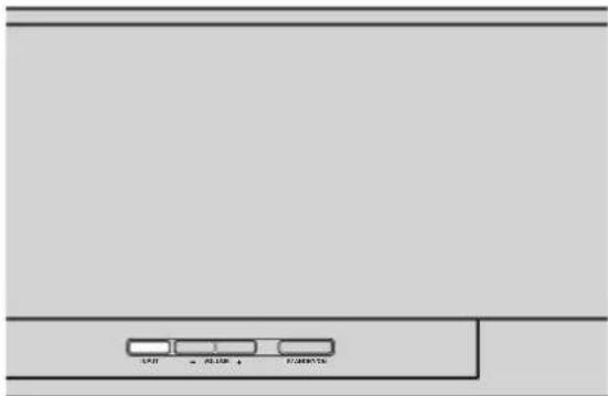
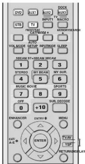
(U.S.A. and Canada models)
■ Front panel operations
Press INPUT on the front panel repeatedly to toggle between TV, STB, DVD, AUX1, AUX2, and AUX3.
The name of the corresponding input source and the type of current input mode are displayed in the front panel display.
■ Remote control operations
[Non-Text]
In addition to controlling this unit, you can also operate other AV components if you set up the remote control with the appropriate remote control codes and set the operation mode selector to TV/AV to change the control area (see page 96).
Press TV to play back a TV program.
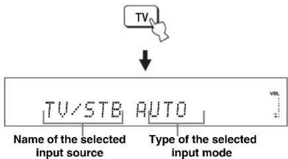
Press STB to play back a satellite broadcast.

Press DVD to play back a DVD.
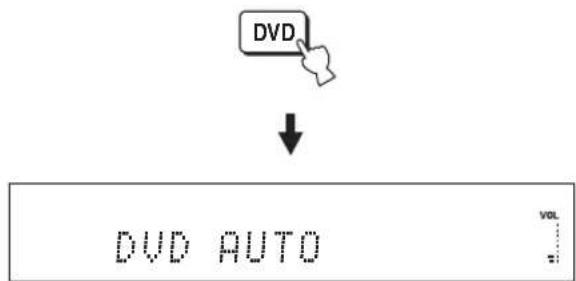
Playback
Press AUX1 (or AUX2) to play back a component connected to the AUX 1 (or AUX 2) jack on the rear panel of this unit.
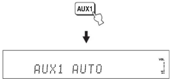
Press AUX3 to play back a component connected to the AUX 3 input jack on the front panel.
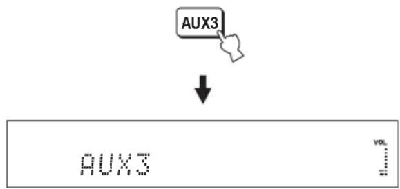
flowchart
graph TD
    A["AUX3"] --> B["↓"]
    B --> C["AUX3 VOL"]
Playing back sources
Once an input source is selected (see page 45), you can play back the selected input source.
Note
This section uses a DVD player as an example of the playback source.

For details on your TV and DVD player, refer to the respective owner's manual.
1 Turn on the power of your DVD player.
2 Switch to the video input on your TV using the remote control supplied with the TV and display the DVD menu screen.
Note
If necessary, turn down the volume of your TV until no sound is heard.
3 Press DVD to select DVD as the input source.

4 Play back DVD on your DVD player using the supplied remote control.
Audio signals from your DVD player are output from this unit.

- You can use the supplied demonstration DVD to check the digital signals being input at the DVD player with the digital connection (optical/coaxial/HDMI). The input channel and LFE indicators light up when this unit detects the 5.1-channel signal input at the optical/coaxial/HDMI jack. If the RGMator lights up, confirm the settings of the digital output, bitstream output, DTS output, and/or HDMI output of the DVD player.
- If the output volume is too low, increase the volume of this unit to around 45.
- If you have set the appropriate remote control codes for your TV and DVD player, you can use the remote control supplied with this unit to operate these components. For details on how to set remote control codes, see page 96.
Adjusting the volume
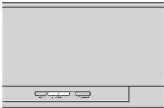
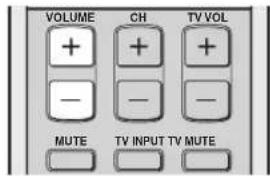
Press VOLUME +/- to increase or decrease the volume level.
The numeric value of the volume level appears in the front panel display.
Control range: MIN (minimum), 01 to 99, MAX (maximum)
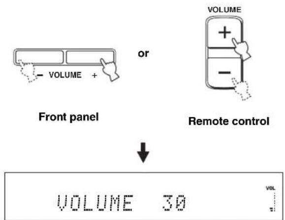
Notes
- The volume level of all input sources (including multi-channel as well as stereo sources) changes at the same time.
- One volume level increases or decreases each time you press VOLUME +/-
- You can continuously increase or decrease the volume level if you press and hold VOLUME +/-
■ Muting the sound
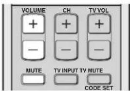
1 Press MUTE to mute the sound.
"AUDIO MUTE ON" appears in the front panel display, and the volume level indicator flashes.
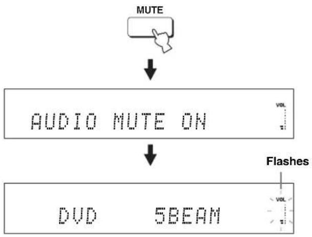
flowchart
graph TD
    A["MUTE"] --> B["AUDIO MUTE ON"]
    B --> C["DVD 5BEAM"]
    D["Flashes"] --> C
2 Press MUTE again (or press VOLUME +/-) to resume the sound output.
"AUDIO MUTE OFF" appears temporarily in the front panel display (or the numeric value of the current volume level appears if you press VOLUME +/-), and the volume level indicator lights up.
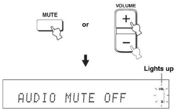
Note
The sound output of all input sources (including multi-channel as well as stereo sources) is muted at the same time.

You can select whether the sound output is to be muted completely or by 20 dB when you press MUTE (see page 78).
FM tuning
There are two tuning methods: automatic and manual. Automatic tuning is effective when the radio signal is strong and there is no interference. If the radio signal is weak, tune into the FM station manually. You can also use the automatic and manual preset tuning features to store up to 40 stations in total (A1 to E8: 5 preset station groups with 8 preset station numbers each).

• This section exceptionally uses the remote control for Europe, Australia, Asia, and Korea models.
- When the operation mode selector is set to TV/AV, you can operate all FM functions. When the operation mode selector is set to YSP, you can only operate the functions described in "Selecting a preset station" (see page 52).
Note
Orient the connected FM antenna for the best reception.
FM controls and functions
■ Remote control functions
Set the operation mode selector (⑧) to TV/AV before tuning or preset tuning.
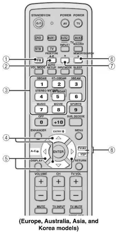
①FM
Selects FM as the input source. This unit is tuned into the last selected FM station.

U.S.A. and Canada models use FM/XM.
②PRESET/TUNE
Switches between the preset search mode and the frequency search mode (see page 51).
③Numeric buttons
Use numbers 1 through 8 to select the preset station numbers (see page 52).
④ENTRY ⇔ (△/▽)
- Selects the preset station numbers (1 to 8) when the colon (:) is displayed in the front panel display (see page 52).
- Selects the tuning frequency when the colon (:) is not displayed in the front panel display (see page 49).
⑤A-E ◆ ( )
Selects the preset station groups (A to E) (see page 51).

U.S.A. and Canada models use CAT/A-E
⑥MEMORY
- Stores a preset station in the memory (see page 51).
- Hold down this button for more than three seconds to start automatic preset tuning (see page 50).
⑦SEARCH
Switches between automatic tuning (the AUTO indicator is turned on) and manual tuning (the AUTO indicator is turned off) (see page 49).
⑧Operation mode selector
Selects the operation mode of this unit.
Automatic tuning
Automatic tuning is effective when the radio station signals are strong and there is no interference.
1 Set the operation mode selector to TV/AV.
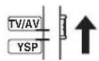
2 Press FM to select FM as the input source.
“FM” appears in the front panel display.
[Non-Text]
- You can also press INPUT on the front panel repeatedly to select FM as the input source.
- If "XM" appears in the front panel display, press FM/XM again to display "FM" (U.S.A. and Canada models only).
3 Press SEARCH repeatedly until the AUTO indicator lights up in the front panel display.
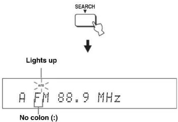
If a colon (:) appears in the front panel display, tuning is not available. Press PRESET/TUNE to turn the colon (:) off.
4 Press ENTRY (4) once to begin automatic tuning.
When this unit is tuned into an FM station, the TUNED indicator lights up and the frequency of the station appears in the front panel display.
- Press to tune into a higher frequency.
- Press to tune into a lower frequency.
![YAMAHA HTY7030 - [Non-Text] - 2](/content/2026/02/375754/images/7bb2c4b0672097a6fb256fd16b04009a1fcc512de6135044333c1e5a165974fb.jpg)
Manual tuning
If the desired FM station signal is weak, tune into it manually.
Note
Manual tuning automatically switches the tuner to the monaural reception mode to increase the signal quality.
1 Set the operation mode selector to TV/AV.

2 Press FM to select FM as the input source.
“FM” appears in the front panel display.
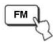
#
- You can also press INPUT on the front panel repeatedly to select FM as the input source.
- If "XM" appears in the front panel display, press FM/XM again to display "FM" (U.S.A. and Canada models only).
3 Press SEARCH repeatedly until the AUTO indicator disappears from the front panel display.
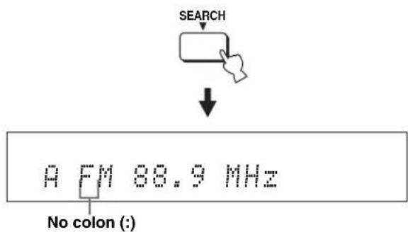
If a colon (:) appears in the front panel display, tuning is not available. Press PRESET/TUNE to turn the colon (:) off.
4 Press ENTRY (✗) to tune into the desired station manually.

Hold down the button for quick search.
Automatic preset tuning
You can use the automatic preset tuning feature to store up to 40 FM stations with strong signals (A1 to E8: 5 preset station groups with 8 preset station numbers each). You can recall the preset stations easily by selecting the preset station groups and numbers.
1 Set the operation mode selector to TV/AV.
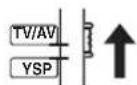
2 Press FM to select FM as the input source.
“FM” appears in the front panel display.
[NO TEXT]
- You can also press INPUT on the front panel repeatedly to select FM as the input source.
- If "XM" appears in the front panel display, press FM/XM again to display "FM" (U.S.A. and Canada models only).
3 Press and hold MEMORY for more than three seconds.
The preset station group and number, the MEMORY indicator, and the AUTO indicator flash. Automatic preset tuning starts from the current frequency and proceeds toward higher frequencies.

When automatic preset tuning is completed, the front panel display shows the frequency of the last preset station.
Notes
- When you overwrite an existing preset station, the previously stored FM station is cleared.
- If the number of automatically preset stations does not reach 40 (E8), this unit automatically stops searching.
- Only FM stations with sufficient signal strength are preset automatically. If the desired station is weak in signal strength, tune into it manually and store it as described in "Manual preset tuning" on page 51.
Manual preset tuning
You can also store up to 40 stations (A1 to E8: 5 preset station groups with 8 preset station numbers each) manually.
1 Set the operation mode selector to TV/AV.
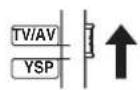
2 Tune into the desired FM station.
See page 49 for tuning instructions.
3 Press MEMORY.
The MEMORY indicator flashes in the front panel display for approximately 10 seconds.
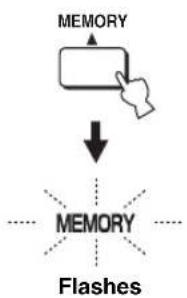
flowchart
graph TD
    A["MEMORY"] --> B["↓"]
    B --> C["MEMORY"]
    C --> D["Flashes"]
4 Press A-E (✗) repeatedly to select a preset station group (A to E) while the MEMORY indicator is flashing.
The selected preset station group letter appears. Check that the colon (:) appears in the front panel display.
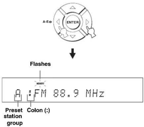
#
- If the colon (:) does not appear, press PRESET/TUNE to display the colon.
• U.S.A. and Canada models use CAT/A-E
• Even when the operation mode selector is set to YSP, you can select the desired preset group by pressing A-E (CAT for U.S.A. and Canada models).
5 Press ENTRY (4) to select a preset station number (1 to 8) while the MEMORY indicator is flashing.
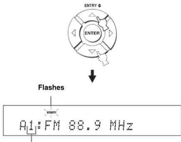
Preset station number
-
- You can also use the numeric buttons to select the desired preset station number.
- Even when the operation mode selector is set to YSP, you can select the desired preset number by pressing △ ▽
6 Press MEMORY while the MEMORY indicator is flashing.
The preset station group and number appear in the front panel display together with the station band and frequency. The MEMORY indicator disappears from the front panel display.
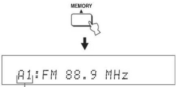
The displayed station has been stored as A1.
Notes
- When you overwrite an existing preset station, the previously stored FM station is cleared.
- The reception mode (stereo or monaural) is stored along with the station frequency.
Selecting a preset station
You can tune into the preset stations simply by selecting the preset station groups and numbers.
1 Set the operation mode selector to TV/AV.
2 Press FM to select FM as the input source.
“FM” appears in the front panel display.

[Symbol]
- You can also press INPUT on the front panel repeatedly to select FM as the input source.
- If “XM” appears in the front panel display, press FM/XM again to display “FM” (U.S.A. and Canada models only).
3 Press A-E (♦) to select the desired preset station group (A to E).
The preset station group letter appears in the front panel display and changes each time you press the button.
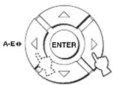
[Non-Text]
- If the colon (:) does not appear, press PRESET/TUNE to display the colon.
• U.S.A. and Canada models use CAT/A-E - Even when the operation mode selector is set to YSP, you can select the desired preset group by pressing A-E (CAT for U.S.A. and Canada models).
4 Press ENTRY (4) to select the desired preset station number (1 to 8).
The preset station group and number appear in the front panel display together with the station band and frequency.
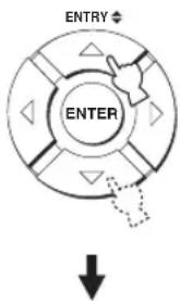
A1:FM 88.9 MHz
#
- You can also use the numeric buttons to select the desired preset station number.
- Even when the operation mode selector is set to YSP, you can select the desired preset number by pressing △ ▽
Displaying the Radio Data System information (Europe model only)
Radio Data System is a data transmission system used by FM stations. You can display the four types of the Radio Data System information: PS (program service), PTY (program type), RT (radio text), and CT (clock time). The corresponding indicators light up in the front panel display.
Notes
- You can select the Radio Data System display modes only when the corresponding Radio Data System indicators are lit in the front panel display. It may take a while for this unit to receive all of the Radio Data System data from the station.
- If the signals being received are not strong enough, this unit may not be able to utilize the Radio Data System data. In particular, the “RT” mode requires a large amount of data and may not be available even when the other Radio Data System display modes are available.
- In case of poor reception conditions, tune into the desired station manually (see page 49).
- In case the signal strength is weakened by external interference while this unit is receiving the Radio Data System data, the reception may be cut off unexpectedly and “...WAIT” appears in the front panel display.
- If the reception is cut off when the “CT” mode is selected, “CT WAIT” appears in the front panel display.
1 Tune into the desired Radio Data System broadcasting station.
We recommend automatic preset tuning to tune into the Radio Data System broadcasting stations (see page 50).
Note
The AUTO PS feature of this unit changes the frequency display to the "PS" mode if the Radio Data System station broadcasts the PS data.
2 Press DISPLAY repeatedly to select the desired Radio Data System display mode.
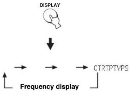
flowchart
graph TD
    A["DISPLAY"] --> B["Frequency display"]
    B --> C["CTRTPTVPS"]
- Select "PS" to display the name of the Radio Data System program.
- Select "PTY" to display the type of Radio Data System program.
- Select "RT" to display the information on the Radio Data System program.
- Select "CT" to display the current time.
Note
In the "RT" mode, this unit can scroll the display with a maximum of 64 alphanumeric characters, including the umlaut symbol. Unavailable characters are displayed with the “_” (underscore).
| Program type Descriptions | |
| NEWS | News |
| AFFAIRS | Current affairs |
| INFO | General information |
| SPORT | Sport |
| EDUCATE | Education |
| DRAMA | Drama |
| CULTURE | Culture |
| SCIENCE | Science |
| VARIED | Light entertainment |
| POP M | Pop music |
| ROCK M | Rock music |
| M.O.R.M | Middle-of-the-road music |
| LIGHT M | Light classical |
| CLASSICS | Serious classical |
| OTHER M | Other music |
Enjoying surround sound
You can enjoy multi-channel surround sound by changing the beam mode using the beam mode buttons on the remote control. Select 5 Beam, Stereo plus 3 Beam, 3 Beam, or My Surround for multi-channel playback.
Notes
- When ANGLE TO WALL OR CORNER is set in MANUAL SETUP (see page 74), 5 Beam and 3 Beam cannot be selected.
- To enjoy 5 Beam, Stereo plus 3 Beam, or 3 Beam as the beam mode, you must perform AUTO SETUP or MANUAL SETUP so that the parameters best match your listening environment.
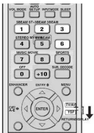
(U.S.A. and Canada models)
1 Set the operation mode selector to YSP.
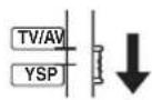
2 Press one of the beam mode buttons (5BEAM, ST+3BEAM, 3BEAM, or MY SUR.) to select the desired beam mode for 5.1-channel play back.
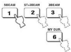
flowchart
graph TD
    A["1"] --> B["2"]
    B --> C["3"]
    C --> D["6"]
    style A fill:#f9f,stroke:#333
    style B fill:#f9f,stroke:#333
    style C fill:#f9f,stroke:#333
    style D fill:#f9f,stroke:#333
5 Beam
Outputs sound beams from the front left, front right, center, surround left, and surround right channels. This mode is ideal for enjoying surround sound effects to the fullest when you watch DVDs recorded in a multi-channel format or play back 2-channel sources in a multi-channel format.
Press 5BEAM to select 5 Beam.
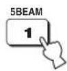
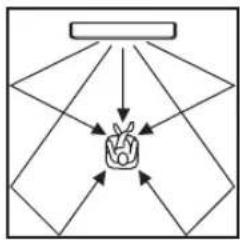
flowchart
graph TD
    A["Input 1"] --> C["F1"]
    B["Input 2"] --> C["F1"]
    D["Input 3"] --> C["F1"]
    E["Input 4"] --> C["F1"]
    F["Input 5"] --> C["F1"]
    C --> G["Output"]
    style C fill:#f9f,stroke:#333
Notes
- To achieve the best surround sound effect, make sure that there are no obstacles placed in the path of sound beams in that the objects may prevent the sound beams from rebounding directly off the walls in your listening room.
- The front left and right sound beams are output toward the walls in your listening room.
- "SP Pos. Corner!" appears in the front panel display if INSTALLED POSITION is set to ANGLE TO WALL OR CORNER (see page 74).
Stereo plus 3 Beam
Outputs normal sound from the front left and right channels and sound beams from the center and surround left and right channels. This mode is ideal for watching live recordings on a DVD. Vocals and instrumental sounds can be heard close to the center of the listening position while sound reflections from the venue itself can be heard on your right and left, giving you the feeling that you are sitting right in front of the stage.
Press ST+3BEAM to select Stereo plus 3 Beam.
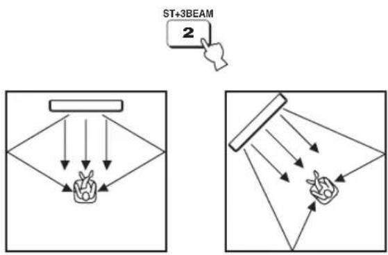
Note
The front left and right sound beams are output directly toward the listening position.
3 Beam
Outputs sound beams from the front left and right and center channels. This mode is ideal for enjoying movies with the whole family. Because the listening position area is widened, you can enjoy excellent quality surround sound over a wider area. In addition, you can use this mode when the listening position is close to the backside of the wall, and the surround left and right sound beams cannot be reflected off the wall.
Press 3BEAM to select 3 Beam.
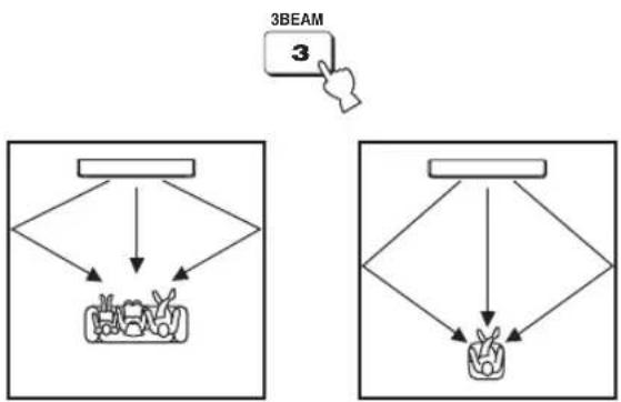
flowchart
graph TD
    A["Device"] --> B["Component 1"]
    A --> C["Component 2"]
    D["3BEAM"] --> E["Device"]
    D --> F["Component 3"]

You can achieve a more realistic surround effect if you adjust settings for IMAGE LOCATION in BEAM MENU (see page 77).
Notes
- When you play back multi-channel sources, surround left and right signals are mixed down and output from the front left and right channels.
- The front left and right sound beams are output toward the walls in your listening room.
- "SP Pos. Corner!" appears in the front panel display if INSTALLED POSITION is set to ANGLE TO WALL OR CORNER (see page 74).
My Surround
This mode enables surround system in a small listening area which may not fulfill the listening room conditions for other beam modes (see “Before installing this unit” on page 16). Use this beam mode when you want to enjoy surround sound near this unit, or when the other beam modes are unavailable.
Press MY SUR. to select My Surround.
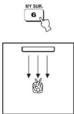
Notes
- Beam mode settings such as beam angles and distances are ineffective in this mode.
- For the full effect of My Surround, your listening position must face toward the front of this unit.
■ Decoder indicators
Depending on the input source and the selected surround mode, the decoder indicators in the front panel display light up as follows:
| Status Indicator | |
| When PCM signals are being input | PCM |
| When DTS digital signals are being input |  |
| When DTS Neo:6 is selected as the surround mode |  |
| When Dolby Digital signals are being input | ☐☐ DIGITAL |
| When Dolby Pro Logic is selected as the surround mode | ☐☐ PL |
| When Dolby Pro Logic II is selected as the surround mode | ☐☐ PL II |
#
- You can select an input mode (AUTO, DTS, or ANALOG) by pressing INPUTMODE repeatedly (see page 87).
- Discs encoded in DTS-ES, Dolby Digital 5.1 EX, Dolby Digital EX, or Dolby Digital Surround EX will be played back in DTS or Dolby Digital.
■ Input channel indicators
Depending on the channel component of the current digital input signal, the input channel indicators in the front panel display light up as follows:
| Status Indicator | |
| When 2-channel stereo signals are being input |  |
| When 5.1-channel signals are being input |  |
■ Surround modes and recommended sources
| Surround mode | Recommended source | |
| Dolby Pro Logic – All sources | ||
| Dolby Pro Logic II | MovieMusicGame | MoviesMusicGames |
| DTS Neo:6 | CinemaMusic | MoviesMusic |
| Neural Surround (U.S.A. and Canada models only) | - | XM Satellite Radio (U.S.A. and Canada models only) |
Notes
- When you select an input source (see page 45), the surround mode used for the previously selected input source is automatically selected.
- If the power of this unit is turned off and on again, the surround mode used for the previously selected input source before the power was turned off is automatically selected.
- If the surround modes are not available, “Prohibit” appears in the front panel display when you press SUR. DECODE.
- The surround modes are available:
- when the beam mode is set to a setting other than the 2-channel or 5-channel stereo playback (see page 60) and My Surround (see page 55).
- when the CINEMA DSP programs are turned off (see page 65).
- when the movie program is selected as the CINEMA DSP program (see page 64). In this case, only Dolby Pro Logic, Dolby Pro Logic II Movie, and DTS Neo:6 Cinema are available.
- when 2-channel signals are being input.
- when the Music Enhancer is turned off (see page 66).
Enjoying 2-channel sources in surround sound
This unit can decode 2-channel sources for 5.1-channel playback so that you can enjoy a variety of surround sound effects by switching the surround mode.

The surround modes are available only when the CINEMA DSP programs are turned off (see page 65) or when the movie program is selected as the CINEMA DSP program (see page 64). In addition, the beam mode must be set to 5 Beam, Stereo plus 3 Beam, or 3 Beam (see page 54), while the Music Enhancer must be also turned off (see page 66).
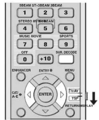
(U.S.A. and Canada models)
1 Set the operation mode selector to YSP.
2 Press SUR. DECODE repeatedly (or press SUR. DECODE and then press √) to switch between surround modes.
Choices: Neo:6 Cinema, Neo:6 Music, PRO LOGIC, PLII Movie, PLII Music, PLII Game, neural surround Default setting: Neo:6 Cinema

flowchart
graph TD
    A["SUR. DECODE"] --> B["ENTER"]
    C["SUR. DECODE"] --> B
    B --> D["Neo:6 Cinema"]
    D --> E["Neo:6 Music"]
    E --> F["PRO LOGIC"]
    F --> G["PLII Movie"]
    G --> H["PLII Music"]
    H --> I["PLII Game"]
    I --> J["neural surround (U.S.A. and Canada models only)"]
Example of the surround mode display in the front panel display when the CINEMA DSP program and the Music Enhancer are turned off
Enjoying TV in surround sound
You can enjoy analog audio signals output from your TV in real surround sound.

Before performing the steps below, set the volume of this unit to 30. If necessary, adjust the volume level in step 4 below.
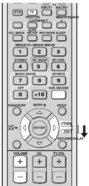
(U.S.A. and Canada models)
1 Select the TV channel you want to watch.
To select a TV channel, use the remote control supplied with your TV.
2 Set the operation mode selector to YSP.
3 Press TV.
This unit outputs audio signals from your TV.

4 If you hear sound from your TV speakers, reduce the volume level of your TV until you can no longer hear any audio being output.
To reduce the TV volume level, use the remote control supplied with your TV.
5 Press VOLUME +/- to adjust the volume level.

6 Press SUR. DECODE repeatedly (or press SUR. DECODE and then press ↕) to switch between surround modes.
Signals input from 2-channel sources are played back in multi-channels.
For more information on surround modes, see page 56.
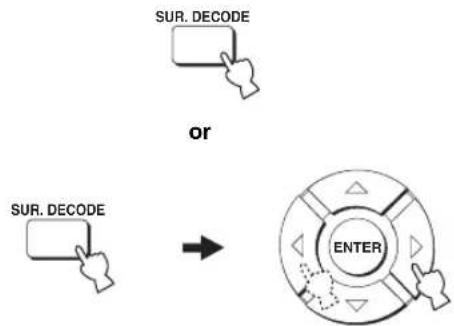
flowchart
graph TD
    A["SUR. DECODE"] --> B["OR"]
    C["SUR. DECODE"] --> B
    B --> D["ENTER"]
Adjusting surround mode parameters
You can configure the parameters for Dolby Pro Logic II Music and DTS Neo:6 Music to fine-tune the surround sound effect.
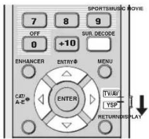
(U.S.A. and Canada models)
1 Repeat steps 1 and 2 in “Enjoying 2-channel sources in surround sound” on page 57 and select PL II Music or Neo:6 Music.
2 Press / to select the parameter.
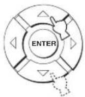
3 Press /◀to▶configure the selected parameter.
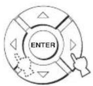
■ When Dolby Pro Logic II Music is selected
PANORAMA
Gives the front left and right channel sound a wraparound effect, distributed throughout the entire surround sound field to give you an expansive feeling.
Choices: ON/OFF
Default setting: OFF
DIMENSION
Adjusts the difference in volume between the front and surround channels to the desired volume balance.
Control range: -3 (toward the surround direction) to +3 (toward the front direction)
Default setting: STD (standard)
C. WIDTH
Distributes the center channel sound to the left and right. If 0 is selected, the center channel sound is output only from the center channel.
Control range: 0 to 7
Default setting: 3
■ When DTS Neo:6 Music is selected
C. IMAGE
Adjusts the center image from three channels (front left and right and center) to varying degrees.
Control range: 0.0 (wider) to 1.0 (toward the center)
Default setting: 0.3
Enjoying stereo sound
You can enjoy 2-channel and 5-channel stereo playback as the beam modes by pressing STEREO on the remote control.
Notes
- When you play back Dolby Digital audio signals in the 2-channel or 5-channel stereo playback, the dynamic range becomes compressed. If the volume level decreases to the extreme, use other beam modes except My Beam.
- When the 2-channel or 5-channel stereo playback is selected as the beam mode, the surround modes (see page 56) and the CINEMA DSP programs (see page 63) become ineffective.
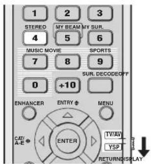
(U.S.A. and Canada models)
2-channel stereo playback
Sounds are output from the front right and left channels. This is ideal for playing back hi-fi sources, such as CDs, and can be used to replace your TV speakers.
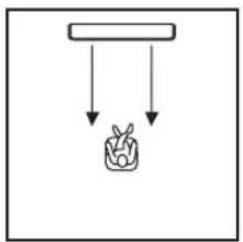
natural_image
Simple line drawing of a container with a downward arrow and a small plant icon below (no text or symbols)
flowchart
graph TD
    A["Start"] --> B["Process Box"]
    B --> C["Output"]
1 Set the operation mode selector to YSP.
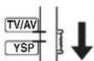
2 Press STEREO to select the 2-channel stereo playback as the beam mode.
“STEREO” appears in the front panel display.
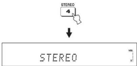
Note
When you play back multi-channel sources, all signals except those from the front left and right channels are mixed down and output from the front left and right channels. No audio is output from the center and surround channels.
5-channel stereo playback
Sounds are output from front left and right, center, and surround left and right. This is ideal for playback in a large listening area or at a party.
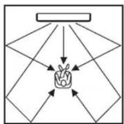
flowchart
graph TD
    A["Start"] --> B{Decision}
    B -->|Yes| C["Path 1"]
    B -->|No| D["Path 2"]
    C --> E["End"]
    D --> E
    E --> F["End"]
1 Set the operation mode selector to YSP.
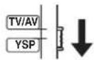
2 Press STEREO twice to select the 5-channel stereo playback as the beam mode.
"5CH STEREO" appears in the front panel display.
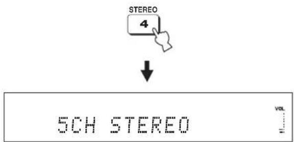
Playing back sound clearly (My Beam)
You can improve listenability in a noisy environment by changing the beam mode to My Beam, which outputs sound beams directly toward the listening position in a single channel. In addition, My Beam is also ideal when you do not want the sound beams to be reflected on the walls in your listening room or when you do not want to disturb other people while enjoying music or movies at night.
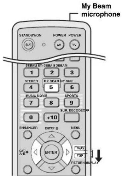
(U.S.A. and Canada models)
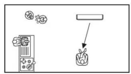
flowchart
graph TD
    A["Device"] --> B["Plant"]
    C["Particles"] --> B
    D["Particles"] --> B
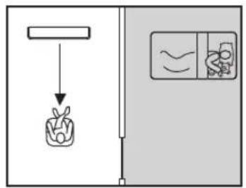
Note
If My Beam is selected as the beam mode, the surround modes (see page 56), the CINEMA DSP programs (see page 63), and TruBass (see page 79) become ineffective. In addition, no audio is output from the subwoofer connected to this unit.
Using auto-adjust function
The My Beam microphone on the remote control collects the test tones from this unit so that the beam angle can be automatically adjusted.
1 Set the operation mode selector to YSP.
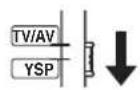
2 Press and hold MY BEAM for more than two seconds.
A test tone is output twice from this unit. Keep pointing the remote control toward this unit while the test tones are being output so that the My Beam microphone can collect the test tones.
Control range: L60° to R60°
Operation guarantee range: 6 m (20 ft), L45° to R45°

Notes
- If an error occurs, an error buzzer is played and "MY BEAM ERROR" is displayed in the front panel display.
- An error may occur if the listening room is noisy. Make sure that the listening room is as quiet as possible while the test tones are being output.
- Do not shake or move the remote control while the test tones are being output.
- Do not cover the My Beam microphone on the remote control while the test tones are being output.
- The batteries in the remote control may be weak if the remote control does not function properly. In this case, replace all the batteries and then try the procedure again.
- When the input signal with 64 kHz or 96 kHz of sampling frequency is being played back, the beam angle cannot be automatically adjusted.
Using manual-adjust function
You can adjust the beam angle manually while playing back an input source. This function is also ideal if the listening position is out of the operation guarantee range of the auto-adjust function.
1 Set the operation mode selector to YSP.
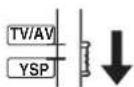
2 Press MY BEAM.
"MY BEAM" is displayed in the front panel display.

3 Press /while "MY BEAM" is displayed to adjust the beam angle.
Control range: L90° to R90°
- Press repeatedly to increase the horizontal angle on the left side.
- Press repeatedly to increase the horizontal angle on the right side.
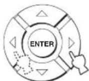

Using sound field programs
This unit is equipped with a variety of precise digital decoders that allow you to enjoy multi-channel playback from stereo or multi-channel sources. This unit is also equipped with a Yamaha CINEMA DSP (digital sound field processing) chip containing several sound field programs used to enhance your playback experience. Most of the CINEMA DSP programs are precise digital recreations of actual acoustic environments found in famous concert halls, music venues, and movie theaters.

The Yamaha CINEMA DSP programs are compatible with all Dolby Digital, DTS, and Dolby Surround sources.
Note
Choose a CINEMA DSP program based on your listening preference and do not purely rely on the name of the CINEMA DSP program itself.
■ What is a sound field?
A significant factor that creates the rich, full tones of a live instrument is the multiple reflections from the walls of the room. In addition to making the sound live, these reflections enable the listener to tell where the player is situated as well as the size and shape of the room in which the listener is sitting.
■ Elements of a sound field
In any environment, there are two distinct types of sound reflections combined with the direct sound coming straight to our ears from the player's instrument to make up the sound field.
Early reflections
Reflected sounds reach our ears extremely rapidly (50 ms to 80 ms after the direct sound) after reflecting from one surface only (from the ceiling or the wall, for example). Early reflections help add clarity to the direct sound.
Reverberations
These are caused by reflections from more than one surface (i.e., wall, ceiling, the back of the room, etc.) so numerous that they merge together to form a continuous sonic afterglow. They are non-directional and lessen the clarity of the direct sound.
Direct sound, early reflections, and subsequent reverberations all together help us determine the subjective size and shape of the room, and it is this information that the digital sound field processor reproduces in order to create the sound fields.
With the appropriate early reflections and subsequent reverberations in your listening room, you can create your own listening environment. The acoustics in your room could be changed to those of a concert hall, a dance floor, or a listening room of virtually any size at all. This ability to create sound fields at will is exactly what Yamaha has done with the CINEMA DSP technology.
CINEMA DSP programs
You can select from three different CINEMA DSP programs (MUSIC, MOVIE, and SPORTS) depending on the type of source you want to enjoy. The CINEMA DSP indicator lights up in the front panel display when one of the CINEMA DSP programs is selected.
Notes
- The CINEMA DSP programs are ineffective when My Surround (see page 55) is selected as the beam mode.
- If the CINEMA DSP programs are not available, "Prohibit" appears in the front panel display when you press one of the CINEMA DSP program buttons on the remote control.
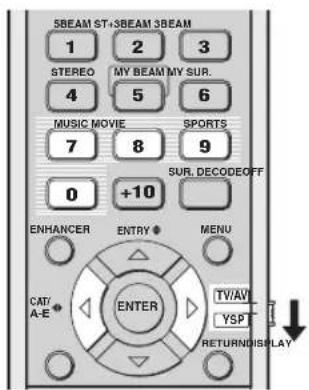
(U.S.A. and Canada models)
■ Music program
Select this CINEMA DSP program when you play back music sources. This program produces a vibrant atmosphere and lets you feel as if you are seated in an actual rock or jazz concert hall.
1 Set the operation mode selector to YSP.
2 Press MUSIC to select the music CINEMA DSP program.

■ Movie program
Select this CINEMA DSP program when you play back movie sources, especially the ones encoded in Dolby Digital, DTS, or Dolby Surround. This program clearly reproduces dialog and sound effects, thus creating a broad and expansive cinematic space amid silence.
1 Set the operation mode selector to YSP.
2 Press MOVIE to select the movie CINEMA DSP program.

■ Sports program
Select this CINEMA DSP program when you play back sports sources. This program densely concentrates the vocal sound of the commentator in the center while broadening the sound from the audience or the environment all around your listening room.
1 Set the operation mode selector to YSP.
2 Press SPORTS to select the sports CINEMA DSP program.

■ Turning off CINEMA DSP programs
Turn off the CINEMA DSP programs if you want to enjoy the original sound without the CINEMA DSP program effect.
1 Set the operation mode selector to YSP.
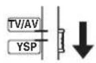
2 Press OFF to turn off the CINEMA DSP programs.
"CINEMA DSP OFF" is displayed in the front panel display and the CINEMA DSP indicator disappears.
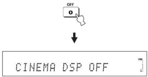
■ Adjusting CINEMA DSP effect levels
You can enjoy good quality sound with the factory preset parameters. However, you can also adjust the effect level of the CINEMA DSP programs relative to the level of the direct sound so that each CINEMA DSP program can reflect your listening environment and your preference even more accurately.
1 Set the operation mode selector to YSP.
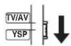
2 Press MUSIC, MOVIE, or SPORTS to select the desired CINEMA DSP program.

or or


3 Press △ /▽.
“DSP LEVEL” is displayed in the front panel display.

4 Press /to adjust the effect level of the selected CINEMA DSP program.
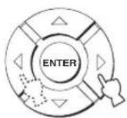
Control range: -6 dB to +3 dB
• A larger value increases the effect level.
- A smaller value decreases the effect level.
Using the music enhancer
You can use the Music Enhancer of this unit to improve the sound nearest to the original depth and width of compression artifacts such as the MP3 format.
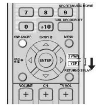
(U.S.A. and Canada models)
1 Set the operation mode selector to YSP.
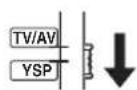
2 Press ENHANCER to select the Music Enhancer.
The currently selected mode appears in the front panel display.

3 Press ENHANCER repeatedly to switch between the Music Enhancer levels (OFF, MIN, and MAX).
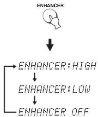
flowchart
graph TD
    A["ENHANCER"] --> B["ENHANCER: HIGH"]
    A --> C["ENHANCER: LOW"]
    A --> D["ENHANCER OFF"]
The ENHANCER indicator lights up when "ENHANCER:HIGH" or "ENHANCER:LOW" is selected.

Notes
- The Music Enhancer is not compatible with the CINEMA DSP programs. If a CINEMA DSP program is selected while the Music Enhancer is on, the Music Enhancer is turned off automatically. In this case, the Music Enhancer remains off even after the CINEMA DSP program is canceled. Likewise, if the Music Enhancer is turned on while a CINEMA DSP program is selected, the CINEMA DSP program is canceled automatically. In this case, the CINEMA DSP program remains off even after the Music Enhancer is turned off.
- The Music Enhancer is available only when a setting other than My Surround (see page 55) is selected as the beam mode.
Using the volume mode (Night listening enhancer/TV volume equal mode)
The night listening enhancers are designed to improve listenability at lower volumes or at night. In addition, you can limit the volume level of the TV so that it will not vary suddenly to a great extent whenever the contents being broadcast change (i.e. due to commercials, etc.).
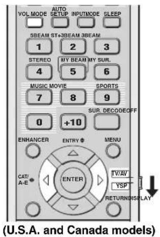
1 Set the operation mode selector to YSP.
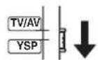
2 Press VOL MODE repeatedly to select NIGHT:CINEMA, NIGHT:MUSIC, TV EQUAL VOLUME, or OFF.
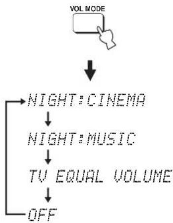
flowchart
graph TD
    A["VOL MODE"] --> B["NIGHT: CINEMA"]
    B --> C["NIGHT: MUSIC"]
    C --> D["TV EQUAL VOLUME"]
    D --> E["OFF"]
The NIGHT indicator lights up in the front panel display when "NIGHT:CINEMA" or "NIGHT:MUSIC" is selected.

The EQUAL indicator lights up in the front panel display when "TV EQUAL VOLUME" is selected.

- Select NIGHT:CINEMA when watching films to reduce the dynamic range of film soundtracks and to make dialog easier to hear at lower volumes.
- Select NIGHT: MUSIC when listening to music sources to preserve ease-of-listening for all sounds.
- Select TV EQUAL VOLUME when watching TV programs.
- Select OFF to turn off the volume mode.
3 Press /to adjust the effect level of compression while NIGHT:CINEMA, NIGHT:MUSIC, or TV EQUAL VOLUME is displayed.
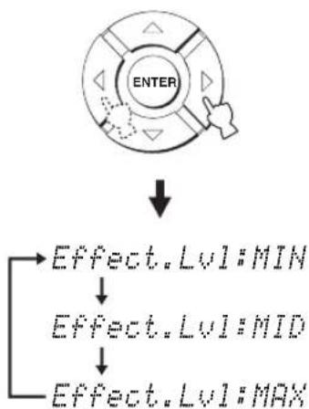
flowchart
graph TD
    A["ENTER"] --> B["Effect.Lvl:MIN"]
    A --> C["Effect.Lvl:MID"]
    A --> D["Effect.Lvl:MAX"]
- Select Effect.Lvl:MIN for minimum compression.
- Select Effect.Lvl:MID for standard compression.
- Select Effect.Lvl:MAX for maximum compression.
Notes
- The volume mode settings are canceled if you press STANDBY/ON or disconnect the AC power supply cable from the AC wall outlet.
- The volume mode settings become ineffective when My Surround is selected as the beam mode (see page 55).
Using the sleep timer
Use this feature to automatically set this unit to the standby mode after a specified period of time. The sleep timer is useful if you are going to sleep after a certain amount of time while this unit is still playing back a source.
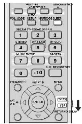
(U.S.A. and Canada models)
Each time you press SLEEP, the front panel display changes as shown below.
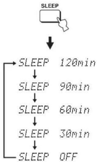
flowchart
graph TD
    A["SLEEP"] --> B["SLEEP 120min"]
    B --> C["SLEEP 90min"]
    C --> D["SLEEP 60min"]
    D --> E["SLEEP 30min"]
    E --> F["SLEEP OFF"]
1 Set the operation mode selector to YSP.
2 Press SLEEP repeatedly to set the interval for the sleep timer.
Choices: 120min, 90min, 60min, 30min, OFF The SLEEP indicator flashes in the front panel display while switching the interval for the sleep timer.

flowchart
graph LR
    A["SLEEP"] --> B["Starburst"]
    B --> C["SLEEP"]
    B --> D["Flashes"]
3 Wait for a few seconds without operating this unit to confirm the setting for the sleep timer.
The SLEEP indicator lights up in the front panel display, indicating that the sleep timer is activated.

■ Canceling the sleep timer
1 Set the operation mode selector to YSP.
2 Press SLEEP repeatedly until "SLEEP OFF" appears in the front panel display.
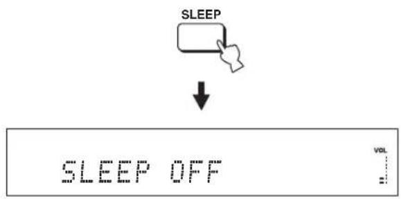
flowchart
graph TD
    A["SLEEP"] --> B["↓"]
    B --> C["SLEEP OFF"]
    C --> D["VOL"]
3 Wait for a few seconds without operating this unit to confirm the setting for the sleep timer.
The SLEEP indicator disappears from the front panel display, indicating that the sleep timer is deactivated.
SLEEP
Disappears
Note
The previous setting for the sleep timer before you deactivate it is stored in the system memory.

The sleep timer setting can also be deactivated if you press STANDBY/ON to set this unit to the standby mode or unplug the AC power supply cable from the AC outlet.
Displaying the input source information
You can display the format and sampling frequency of the current input signal in the front panel display.
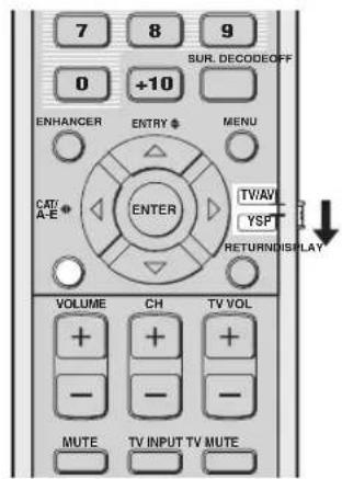
(U.S.A. and Canada models)
1 Set the operation mode selector to YSP.
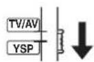
2 Press DISPLAY.
The information on the current input signal is displayed as follows:
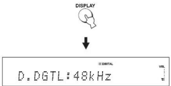
or

| Input signal Indicator | Sampling frequency |
| Dolby digital DOLBY DGTL | 32/44.1/48/64/88.2/96 kHz |
| DTS DTS | |
| PCM PCM | |
| Analog ANALOG – |
[Symbol]
When the input signal is unclear, “____” is displayed for the sampling frequency.
Using the HDMI control feature
You can operate the following functions using the remote control supplied with your TV if this unit and an HDMI control-compatible TV (except some models) are connected via HDMI.
- Turning on or off the power (synchronized operation with the TV)
- Selecting the audio output component (TV or this unit)
- Adjusting the volume level (up/down and mute)
An example of the HDMI control-compatible component is a Panasonic EZ Sync (for U.S.A. and Canada) or Viera Link (for other countries)-compatible component (TV, DVD recorder, Blu-ray recorder, etc.).

If you connect this unit to an HDMI control-compatible DVD player or Blu-ray Disc player via HDMI, you can also control the connected component in synchronization with this unit (except some models).
1 Connect this unit to your HDMI control-compatible TV via HDMI.
For details about HDMI and HDMI components, see “Information on HDMI™” on page 20 and “Connections using HDMI cables” on page 21. Also in the owner’s manual supplied with your TV, refer to the information on connecting an AV amplifier.
2 Turn on the power of all components connected via HDMI.
For details about controlling external components, see the owner's manuals supplied with your components.
3 Check the system settings for all components connected via HDMI and activate the HDMI control feature.
For details about setting external components, see the owner's manuals supplied with your components. Once you have followed steps 1 to 3, you do not need to carry out the same procedure again next time.
4 Turn off the power of your TV and then turn on the power again.
5 Set the input source selector of your TV to this unit (HDMI, etc.).
6 Select the connected component as the input source by pressing INPUT on the front panel of this unit (or press one of the input selector buttons on the remote control). Confirm that the video image played back on the DVD recorder (etc.) appears in your TV correctly.
7 Use the remote control supplied with your TV to turn on or off the power, select the audio output component, and adjust the volume level of this unit.
Notes
- Check the following if you cannot operate this unit in synchronization with your TV.
- Whether HDMI CONTROL is set to ON (see page 82).
- Whether the HDMI control feature is activated for your TV (see the owner's manual supplied with your TV).
- While you are playing back audio from a non-HDMI component, turning off the power of your TV with the remote control supplied with your TV does not turn off the power of this unit. Playback continues without being affected.
MANUAL SETUP
To achieve the best quality surround sound, you can use MANUAL SETUP to fine-tune the listening environment parameters, as well as to make advanced settings for sound signals, sound beams, digital input, and the OSD. Change the initial settings (indicated in bold under each parameter) to reflect the needs of your own listening environment.
#
- You can save the settings optimized by the AUTO SETUP procedure (see page 42). A set of settings optimized according to the specific conditions of your listening environment can be recalled later depending on the varying conditions of your listening environment (see page 43).
- Most of the parameters in SOUND MENU and BEAM MENU are automatically set when you run AUTO SETUP (see page 35). Use SOUND MENU and BEAM MENU to make additional adjustments.
- BEAM MENU allows you to make settings for the surround sound effects normally available in the speaker settings menu.
- Make settings for the parameters in BEAM MENU first before making settings for the parameters in SOUND MENU, INPUT MENU, and DISPLAY MENU.
SOUND MENU
Use to manually adjust the various parameters related to the sound output.
| Item Features Page | ||
| TONE CONTROL Adjusts the output level of high-frequency or low-frequency sound. | 78 | |
| SUBWOOFER SET Adjusts the various subwoofer settings. | 78 | |
| MUTE LEVEL Adjusts the muting level. | 78 | |
| AUDIO DELAY Adjusts the audio delay. | 79 | |
| ROOM EQ Adjusts the tonal quality of the listening room. | 79 | |
| DD/DTS Dynamic Range Adjusts the dynamic range of Dolby Digital or DTS signals. | 79 | |
| TruBass Selects the bass sound enhancer. | 79 | |
BEAM MENU
Use to manually adjust the various parameters related to the sound beam output.
| Item Features Page | |
| SETTING PARAMETERS Adjusts the listening room and listening position settings. | 74 |
| BEAM ADJUSTMENT Adjusts the various sound beam settings. | 75 |
| IMAGE LOCATION Adjusts the sound position of the front left and right channels. | 77 |
INPUT MENU
Use to manually adjust the various parameters related to the audio and video input.
| Item Features Page | ||
| INPUT ASSIGNMENT | Assigns jacks according to the component to be used. | 80 |
| INPUT MODE Selects the initial input of the source. | 80 | |
| INPUT TRIM | Adjusts the input level of the source. | 80 |
| INPUT RENAME | Renames the displayed input source. | 81 |
| HDMI SET Adjusts the various HDMI settings. | 81 | |
| XM ANTENNA LEVEL (U.S.A. and Canada models only) | Displays the current reception level of the XM Satellite Radio signal. | 82 |
DISPLAY MENU
Use to manually adjust the various parameters related to the display.
| Item Features Page | ||
| F.DISPLAY SET | Adjusts the front panel display settings. | 83 |
| OSD SET | Adjusts the OSD settings. | 83 |
| UNIT SET | Changes the display unit of measurement. | 83 |
Using MANUAL SETUP
Use the remote control to access and adjust each parameter.
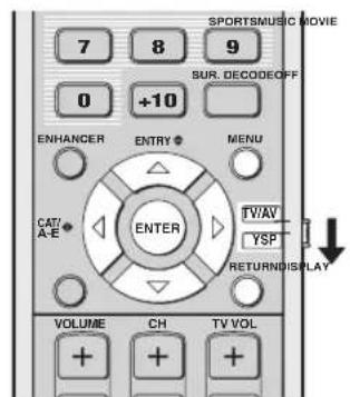
(U.S.A. and Canada models)
#
You can adjust the SET MENU parameters while the unit is reproducing sound.
1 Set the operation mode selector to YSP.
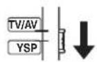
2 Press MENU.
The SET MENU screen appears on your TV.
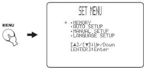
flowchart
graph LR
    A["MENU"] --> B["SET MENU"]
    B --> C["• MEMORY\n• AUTO SETUP\n• MANUAL SETUP\n• LANGUAGE SETUP\n[♠"]/[♥]:Up/Down\n["ENTER"]:Enter]
#
- The control buttons used for SET MENU are displayed at the bottom of the screen.
- To return to the previous screen while using SET MENU, press RETURN.
- To exit from the SET MENU screen, press MENU once more.
- You can also perform the following operations in the front panel display.
3 Press / to select MANUAL SETUP and press ENTER.
The following screen appears on your TV.
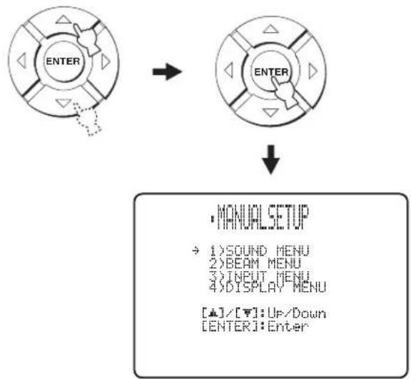
flowchart
graph TD
    A["ENTER"] --> B["ENTER"]
    B --> C["• MANUAL SETUP\n→ 1) SOUND MENU\n2) BEAM MENU\n3) INPUT MENU\n4) DISPLAY MENU\n[▲"]/[▼]: Up/Down\n["ENTER"]: Enter]
4 Press / to select a sub menu and press ENTER.
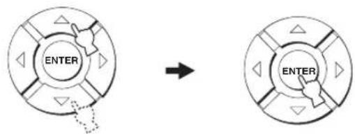
flowchart
graph TD
    A["ENTER"] --> B["→"]
    B --> C["ENTER"]
5 Press /4/ and ENTER to configure each parameter.

6 Press MENU to exit.
The OSD disappears from your TV screen.
MENU

BEAM MENU
Use to manually adjust the various parameters related to the sound beam output.
SET MENU → MANUAL SETUP → BEAM MENU
2.500
→ A) SETTING PARAMETERS B) BEAM ADJUSTMENT C) IMAGE LOCATION
[▲]/[▼]:Up/Down

You can adjust the sound beam output level of each channel in "Adjusting the audio balance" (see page 84).
■ SETTING PARAMETERS
(Setting parameters)
Use to set the position of this unit in your listening room and the distance of this unit from the listening position. When you make settings for each parameter, other related parameters are automatically adjusted to best match your listening environment.
Note
If you make adjustments in SETTING PARAMETERS, the beam optimization settings made in the AUTO SETUP procedure will be lost. If you want to keep the beam optimization settings made in the AUTO SETUP and make further adjustments, adjust settings in BEAM ADJUSTMENT first (see page 75).
A) SETTING PARAMETERS 1/3
→ INSTALLED POSITION ……FLAT TO WALL
[&]/[#]:Up/Down [-#]/[#]:Sel
INSTALLED POSITION
(Installed position of this unit)
Use to adjust the installed position of this unit.
Choices: FLAT TO WALL (Parallel to wall installation), ANGLE TO WALL OR CORNER
(Corner installation)
FLAT TO WALL

natural_image
Blank white rectangular paper with a small rectangular top line (no text or symbols)ANGLE TO WALL
OR CORNER

natural_image
Simple geometric shape: a diagonal line inside a square frame (no text or symbols)- Select FLAT TO WALL if this unit is installed in parallel with the wall in your listening room. Adjust the width and length of your listening room as well as the distance of the listening position from this unit and the distance of the center of this unit from the left wall.
Listening position from the left wall
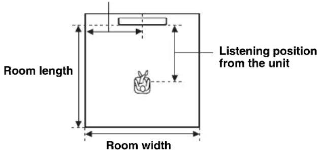
Choices for the room width and length:
2.0 m to 12.0 m (6.5 ft to 40.0 ft)
Choices for the listening position from this unit: 1.8 m to 9.0 m (6.0 ft to 30.0 ft)
Choices for the listening position from the left wall: 0.6m to 11.4m (2.0 ft to 38.0 ft)
Room width and length
0 1 200 000 000 000 000 1 1 1 1 1 1 1 1 1 1 1 1 1 1 1 1 1 1 1 1 1 1 1 1 1 1 1 1 1 1 1 1 1 1 1 1 1 1 1 1 1 1 1 1 1 1 1 1 1 1 0
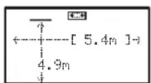
[4]/[1]:Up/Down [4]/[1]:Se1

- Select ANGLE TO WALL OR CORNER if this unit is installed in the corner of your listening room. Adjust the width and length of your listening room as well as the distance of the listening position from this unit.
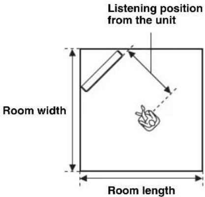
Choices for the room width and length:
2.0 m to 12.0 m (6.5 ft to 40.0 ft)
Choices for the listening position from this unit:
1.8 m to 9.0 m (6.0 ft to 30.0 ft)
Room width and length
![A\SETTING PARAMETERS 2/3 +---- 5.4m ---- [ 5.4m ] [▲]/[▼]:Up/Down [ -■]/[ △]:Sel [ENTER]:Return](/content/2026/02/375754/images/59ef50e950bc215c8dcd8b7d7e50dbf6c018c44c739b1ae6ff24f14cb4c62a93.jpg)
Listening position from the unit
![ASetting Parameters V3 [2.5m] [S] [4]/[4]:Up/Down [4]/[4]:Se1 [ENTER]:Return](/content/2026/02/375754/images/0007e898ecb5b2296bbd1db38ff1b08ce677c32ccaf4a43b20217c13173e89ad.jpg)
Note
When you set the INSTALLED POSITION parameter in MANUAL SETUP (see page 74), the parameters newly set for the width and length of your listening room are automatically set as the factory default value.
■ BEAM ADJUSTMENT (Beam adjustment)
Use to manually adjust the various sound beam settings. We recommend that you select 5 Beam as the beam mode before adjusting these parameters (see page 54).
Notes
- When INSTALLED POSITION is adjusted in MANUAL SETUP (see page 74), the factory default value is automatically set for this parameter except Center in FOCAL LENGTH (see page 76).
- Depending on the beam mode settings (see pages 54 and 60), some channel positions may not be available for selection. In this case, “—” is displayed. When using Stereo plus 3 Beam as the beam mode, set the surround left and right signals to be output from the front left and right channels.
![SYSTEM ADJUSTMENT + a) HORIZONTAL ANGLE b) BEAM TRAVEL LENGTH c) FOCAL LENGTH d) TREBLE GAIN [+] / [T]: Up/Down [ENTER]: Enter](/content/2026/02/375754/images/fdc2d55a09086599f978e566d1f9f2bb2e6ae12f81b8a61dc7a9f5f9fa28e73d.jpg)
HORIZONTAL ANGLE (Horizontal angle)
Use to adjust the horizontal angle of sound beams for each channel. By adjusting the horizontal angle of the sound beams, you can optimize the sound beam paths. A test tone is automatically output.
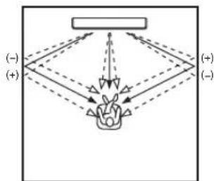
flowchart
graph TD
    A["Input"] --> B{Decision}
    B -->|Yes| C["Process"]
    B -->|No| D["Output"]
    C --> E["Final Output"]
    D --> E
    style A fill:#f9f,stroke:#333
    style E fill:#bbf,stroke:#333
Choices: L90° to R90°
Adjust toward L (left) to move the direction of the output to the left and adjust toward R (right) to move it to the right.
![a)HORIZONTAL ANGLE 1/5 Front L L65deg L90 5 beam R90 * 0(deg) [▲]/[▼]:Up/Down [←]/[←]:Sel [ENTER]:Return](/content/2026/02/375754/images/018f554e18250d5c5a63d08b324d6fd1efe455097c34272ca7172c4e187c53a1.jpg)
BEAM TRAVEL LENGTH (Beam travel length)
A certain amount of delay must be applied to the sound from each channel so that all sounds can arrive at the listening position at the same time. This menu sets the distance that sound beams travel after being output and reflected off the wall until they arrive at the listening position and adjusts the delay applied to the respective channel.
The lines in the illustration below indicate the distance.
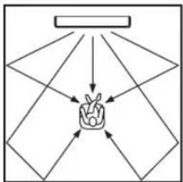
flowchart
graph TD
    A["Input"] --> B["Process"]
    B --> C["Output"]
    style A fill:#f9f,stroke:#333
    style B fill:#ccf,stroke:#333
    style C fill:#cfc,stroke:#333
Choices: 0.3 m to 24.0 m (1.0 ft to 80.0 ft)
- Front L adjusts the distance the front left channel sound beams travel.
- Front R adjusts the distance the front right channel sound beams travel.
- Center adjusts the distance the center channel sound beams travel.
- Surround L adjusts the distance the surround left channel sound beams travel.
- Surround R adjusts the distance the surround right channel sound beams travel.
![5 BEAM TRAVEL LENGTH S beam → Front L·······6.0m Front R·······6.0m Center·······2.5m Surround L·····9.1m Surround R·····9.1m [4]/[7]:Up/Down [4]/[8]:Sel [ENTER]:Return](/content/2026/02/375754/images/aa49e9e4db363d2eabc8e189c470f1e6bd258fe6c08727138d2553e924d992d7.jpg)

We recommend that you use the setting optimized by AUTO SETUP (see page 35). Adjust this parameter only when you changed HORIZONTAL ANGLE (see page 75).
FOCAL LENGTH (Focal length)
Use to set the distance from the front of this unit to the focal point of output for each channel to achieve an expansive feeling for each channel.
The focal points except for the center channel should be set near the reflection points on the walls. The shorter the distance, the larger the expansion.
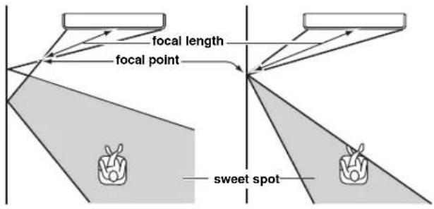
Front left channel Center channel
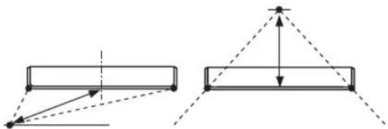
natural_image
Pure geometric diagram showing two rectangular shapes with dashed lines and arrows, no text or symbols presentChoices: -1.0 m to +13.0 m (-3.5 ft to +43.5 ft)
Adjust toward - (minus) to move the focus outward and adjust toward + (plus) to move the focus toward the normal position.
- Front L adjusts the focal length for the front left sound beams.
- Front R adjusts the focal length for the front right sound beams.
- Center adjusts the focal length for the center sound beams. Initial setting: -0.5m (-1.5 ft)
- Surround L adjusts the focal length for the surround left sound beams.
- Surround R adjusts the focal length for the surround right sound beams.

We recommend that you use the initial setting (-0.5 m (or 1.5 ft)) for the center channel.
![C)POCAL LENGTH 5 beam → Front L....+1.5m Front R....+1.5m Center....+0.5m Surround L....+2.3m Surround R....+2.3m [4]/[7]:Up/Down [4]/[8]:Se [ENTER]:Return](/content/2026/02/375754/images/a42fb4484b2d074914dfac8b84e2f5116c442466ffa4a043159b37dc7d1b0503.jpg)
TREBLE GAIN (Treble gain)
Use to adjust the high-frequency output level of each channel.

If the reflection points of the front left and right or surround left and right sound beams are on curtain or other acoustically absorbent surfaces, you can achieve more effective surround sound by increasing the treble level for those sound beams.
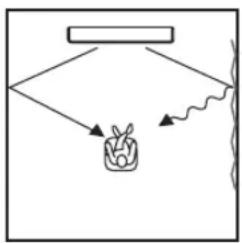
flowchart
graph TD
    A["Rectangular Box"] --> B["Plant"]
    B --> C["Wavy Line"]
    style A fill:#f9f,stroke:#333
    style C fill:#ccf,stroke:#333
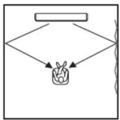
flowchart
graph TD
    A["Rectangular Box"] --> B["Container"]
    B --> C["Vertical Line"]
Choices: -12.0 dB to +12.0 dB
Initial setting: 0 dB
- Front L adjusts the high-frequency output level of the front left channel.
- Front R adjusts the high-frequency output level of the front right channel.
- Center adjusts the high-frequency output level of the center channel.
- Surround L adjusts the high-frequency output level of the surround left channel.
- Surround R adjusts the high-frequency output level of the surround right channel.
![d)TREADLE GAIN + Front L:······:0dB ---+---+ Front R:······:0dB ---+---+ Center:······:0dB ---+---+ Surround L:······:0dB ---+---+ Surround R:······:0dB ---+---+ [+]/[+] :Up/Down [-]/[+] :SeI [ENTER]:Return](/content/2026/02/375754/images/fbe6bab62433061b82f9c70f328d2c72ed0badef8be086f2900c5a76bf44c783.jpg)
■ IMAGE LOCATION (Image location)
Use to adjust the direction from which the front left and right channel sound is heard so that each sound can be heard closer to the center channel.
Use this feature to redirect audio signals if the sound coming from the front left and right channels seems unnatural, such as when your listening position is not the center of your listening room.
You can only adjust this parameter when 3 Beam or 5 Beam is selected as the beam mode (see page 54).
Choices: ON, OFF
Setting range: 0% to 95%
Initial setting: 0%
![C)IMAGE LOCATION → OFF ON L C R LEFT............0% RIGHT............0% [4]/[▼]:Up/Down [=0]/[▼]:Sel [ENTER]:Return](/content/2026/02/375754/images/b627012cca9d915aaafd09264df071c9f345595fcea414c9235c0fa884fc098f.jpg)
LEFT (Left)
Adjusts audio signals toward the left.
The higher the percentage, the louder the output from the center.
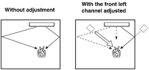
flowchart
graph TD
    A["Without adjustment"] --> B["Object"]
    C["With the front left channel adjusted"] --> D["Object"]
    D --> E["Object"]
    style A fill:#f9f,stroke:#333
    style C fill:#f9f,stroke:#333
    style D fill:#f9f,stroke:#333
    style E fill:#f9f,stroke:#333
RIGHT (Right)
Adjusts audio signals toward the right.
The higher the percentage, the louder the output from the center.
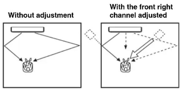
flowchart
graph TD
    A["Without adjustment"] --> B["Object with arrow"]
    C["With the front right channel adjusted"] --> D["Object with arrow"]
    D --> E["Object with arrow"]
    style A fill:#f9f,stroke:#333
    style C fill:#f9f,stroke:#333
    style D fill:#f9f,stroke:#333
SOUND MENU
Use to manually adjust the various parameters related to the sound output.
SET MENU → MANUAL SETUP → SOUND MENU
![1) SOUND MENU → A) TONE CONTROL B) SUBWOOFER SET C) MUTE LEVEL D) AUDIO DELAY E) ROOM EQ F) DD/PTS Dynamic Range G) TrueBass [4]/[5]: Up/Down [ENTER]: Enter](/content/2026/02/375754/images/53452284ff56ce9a39a57f2db5b253404a2143313e151ec2fd4feeeb764a43a8.jpg)
■ TONE CONTROL (Tone control)
You can adjust the tonal quality of sound beams.
![A/TORE CONTROL → TREBLE···0dB - + - BASS···0dB - + - [4]/[7]:Up/Down [-]/[8]:Sel [ENTER]:Return](/content/2026/02/375754/images/3f377f689b004396093c7b77ac9ecb1d0aa1cf04bc19b0a6d7f1a7f254f98e8f.jpg)
TREBLE (Treble)
Use to adjust the high-frequency response.
Choices: -12 dB to +12 dB
Initial setting: 0 dB
BASS (Bass)
Use to adjust the low-frequency response.
Choices: -12 dB to +12 dB
Initial setting: 0 dB
■ SUBWOOFER SET (Subwoofer settings)
Use to manually adjust the various subwoofer settings.
![B/SUBWOOPER SET → BASS OUT···FRONT CROSS OVER···100Hz LFE LEVEL···0dB DISTANCE···3.0m [4]/[M]:UP/Down [4]/[M]:Sel [ENTER]:Return](/content/2026/02/375754/images/bea3c96687c4c88a48e38809977746c29952153b875f12a9529c6ccbb150c8db.jpg)
BASS OUT (Bass out)
Low-frequency (bass) signals can be directed to the subwoofer and/or the front left and right channels. This setting also determines the routing of LFE (low-frequency effect) signals found in Dolby Digital or DTS sources.
Choices: SWFR (Subwoofer), FRONT
- Select SWFR if you connect a subwoofer. LFE and low-frequency signals from other channels are directed to the subwoofer.
- Select FRONT if you do not use a subwoofer. LFE and low-frequency signals from other channels are directed to the front left and right channels.
CROSS OVER (Crossover)
When BASS OUT is set to SWFR, you can use this feature to select a crossover (cutoff) frequency for all low-frequency signals. All frequencies below the selected frequency will be sent to the subwoofer position.
Choices: 80Hz, 100Hz, 120Hz
LFE LEVEL (Low-frequency effect level)
Select to adjust the output level of the LFE (low-frequency effect) channel according to the capacity of your subwoofer. The LFE channel carries low-frequency special effects which are only added to certain scenes.
This setting is effective only when this unit decodes Dolby Digital or DTS signals.
Choices: -20 to 0 dB
DISTANCE (Distance)
Select to adjust the distance of the subwoofer from the listening position.
Choices: 0.3 to 15.0 m (1.0 ft to 50.0 ft)
Initial setting: 3.0 m (10.0 ft)
■ MUTE LEVEL (Muting level)
Use to adjust how much the mute function reduces the volume level.
Choices: MUTE, -20 dB
- Select MUTE to completely halt all sound output.
- Select -20 dB to reduce the current volume level by 20 dB.
![COMUTE LEVEL ▶MUTE -20dB [=0/[ ]:Select [ENTER]:Return](/content/2026/02/375754/images/9d2639f9e05051aaf789de71e20ecac1a8efb4e2f77f7d1e3bafce30db29a22c.jpg)
■ AUDIO DELAY (Audio delay)
Use to delay the sound output and synchronize it with the video image. This may be necessary when using certain LCD monitors or projectors.
Choices: 0 to 160 msec
D: 1000 DELAY
AUDIO DELAY.....@msec
[4]/[9]:Select
■ ROOM EQ (Room equalizer)
Use to change the tonal qualities of your listening room when the unit is mounted on the wall.
Choices: MOUNTING (Mount type), REFLECTING (Reflectivity type)
EROOM EQ
→ MOUNTING···SHELF
REFLECTING···NORMAL
[.]/[ ]:UP/Down [-0/ [ ]:Sel
MOUNTING (Mounting type)
Use to enhance medium to low range sounds.
Choices: WALL (Wall mount), SHELF (Shelf mount)
- Select WALL if this unit is mounted on the wall in your listening room.
- Select SHELF if this unit is mounted on the shelf in your listening room.
REFLECTING (Reflectivity type)
Use to select the reflectivity of your listening room.
Choices: NORMAL (Normal), HI ECHO (High echo)
- Select NORMAL if your listening room has a normal reflectivity.
- Select HI ECHO if your listening room has highly reflective surfaces such as concrete walls.
■ DD/DTS Dynamic Range
(Dynamic range of Dolby Digital and DTS signals)
Use to select the amount of dynamic range compression. This setting is effective only when the unit is decoding Dolby Digital and DTS signals. Dynamic range is the difference between the smallest sound that can be heard above the noise of the equipment and the biggest sound that can be heard without distortion.
Choices: MIN (minimum), STD (standard),
MAX (maximum)
F)DD/OTS Dynamic Range
MIN STD MAX
Select to adjust the dynamic range compression.
- Select MIN for listening to sources at low volume levels.
- Select STD for general use.
- Select MAX for feature films.
TruBass
Use to turn on or off the bass sound enhancer. The SRS TruBass technology improves bass even without a subwoofer and provides deeper, richer bass in the presence of a subwoofer.
Choices: OFF, ON
![GTNPass OFF ON ▶ [=0/[=1]:Select [ENTER]:Return](/content/2026/02/375754/images/9df7c4269ddac294b33a96bc821c5d88298f5357289c41ebe44a86aad03e8e83.jpg)
Note
TruBass is not available when My Beam (see page 61) or My Surround (see page 55) is selected as the beam mode.
INPUT MENU
Use to manually adjust the various parameters related to the audio and video input.
SET MENU → MANUAL SETUP → INPUT MENU
![3)INPUT MENU → A)INPUT ASSIGNMENT B)INPUT MODE C)INPUT TRIM D)INPUT RENAME E)HDMI SET F)XM ANTENNA LEVEL [4]/[5]:Up/Down [ENTER]:Enter](/content/2026/02/375754/images/7adf03f7f9fc7f4f9ce9f1fc1bf27ee11616285d4d1badea7af78c3235396744.jpg)
Note
“F) XM ANTENNA LEVEL” is for U.S.A. and Canada models only.
■ INPUT ASSIGNMENT (Input assignment)
Use to assign the HDMI IN jacks of this unit to other components if the initial settings of this unit do not correspond to your needs. By assigning other components to the HDMI IN jacks of this unit, you can display the names of the connected components in the front panel display and OSD and operate the components with the input selector buttons of the same name. If you connect a component to one of the HDMI IN jacks of this unit and do not assign a name to it, the default component name for HDMI IN jack is displayed in the front panel and OSD when selected.
- Select HDMI1 to assign a component to the HDMI AUX 1 IN jack of this unit.
Choices: TV/STB, AUX1
- Select HDMI2 to assign a component to the HDMI DVD IN jack of this unit.
Choices: DVD, AUX2
![A) INPUT ASSIGNMENT HDMI → HDMI1···AUX1 ( DUX1 ) HDMI2···DUD ( DVD ) [4]/[7]:Up/Down [ 4]/[ 8]:Sel [ENTER]:Return](/content/2026/02/375754/images/08e56834518aa2b95ac57e51f5c2e04300ad17296ab996a1d292e219bff70862.jpg)
■ INPUT MODE (Input mode)
Use to designate the input mode for the input sources connected to the DIGITAL INPUT jacks when you turn on the power of this unit. For information on the types of audio signals that can be output by this unit, see “Selecting the input mode” on page 87.
Choices: AUTO, LAST
![B)INPUT MODE ▶AUTO LAST [0]/[0]:Select [ENTER]:Return](/content/2026/02/375754/images/b002765e6d6031c75aa78f737eea4ac193c0adc92264df9b089c46288acf4024.jpg)
- Select AUTO to set this unit to automatically detect the type of input signals and select the appropriate input mode.
- Select LAST to set this unit to automatically select the last input mode used for that input source. If the type of input signals is different from the setting, no sounds will be produced.
■ INPUT TRIM (Input trim)
Use to adjust the input level of the input source.
![C:\INPUT TRIM 1/2 → TV/STB ANALOG:---3.0dB DIGITAL:---3.0dB DUD DIGITAL:---3.0dB [+]/[ ]:Up/Down [■]/[ ]:Sel [ENTER]:Return](/content/2026/02/375754/images/b71fa86e198a6bb779d2f1344e14dfa6268ca76303c6674bcc5359e6ef21322b.jpg)
- Select TV/STB ANALOG to adjust the level of audio and video signals input at the TV/STB AUDIO INPUT jacks of this unit.
Control range: -6.0 dB to 0.0 dB Initial setting: -3.0 dB
- Select TV/STB DIGITAL to adjust the level of audio and video signals input at the TV/STB OPTICAL DIGITAL INPUT jack of this unit.
Control range: -6.0 dB to 0.0 dB Initial setting: -3.0 dB
- Select DVD DIGITAL to adjust the level of audio and video signals input at the DVD COAXIAL DIGITAL INPUT jack of this unit.
Control range: -6.0 dB to 0.0 dB Initial setting: -3.0 dB
- Select AUX1 ANALOG to adjust the level of audio and video signals input at the AUX 1 AUDIO INPUT jacks of this unit.
Control range: -6.0 dB to 0.0 dB Initial setting: -3.0 dB
- Select AUX1 DIGITAL to adjust the level of audio and video signals input at the AUX 1 OPTICAL DIGITAL INPUT jack of this unit.
Control range: -6.0 dB to 0.0 dB Initial setting: -3.0 dB
- Select AUX2 DIGITAL to adjust the level of audio and video signals input at the AUX 2 COAXIAL DIGITAL INPUT jack of this unit.
Control range: -6.0 dB to 0.0 dB Initial setting: -3.0 dB
- Select AUX3 ANALOG to adjust the level of audio signals input at the AUX 3 input jack on the front panel.
Control range: -6.0 dB to 0.0 dB Initial setting: -3.0 dB
- Select DOCK ANALOG to adjust the level of audio signals input at the DOCK terminal of this unit (U.S.A., Canada, and Australia models only).
Control range: -6.0 dB to 0.0 dB Initial setting: -3.0 dB
■ INPUT RENAME (Input rename)
Use to change the name of the input source in the OSD and the front panel display. Press an input selector button (e.g., DVD) to select the component you want to change the name for and perform the following procedure.
![D) INPUT RENAME DVD -> DVD ____ [■]/[■]:Position [■]/[■]:Character [ENTER]:Return](/content/2026/02/375754/images/3a69b0a0bb98e35837dc7fdca4c2b011e5ee99075558f9dc3fd7c3aef99d0f3a.jpg)
1 Press / to place the \_ (underscore) under the space or the character you want to edit.
The _ (underscore) flashes.
2 Press / to select the desired character.
- You can use up to 8 characters for each input.
- Press to change the character in the following order or press to go in the reverse order:
A to Z, a space, 0 to 9, a space, a to z, a space, #, *, +, etc.

3 Repeat steps 1 to 2 to rename each input.
4 Press ENTER to exit.
The new names are registered, and the display returns to the previous screen.

■ HDMI SET (HDMI settings)
Use to change the HDMI audio/video output/input to match the connected component.
Choices: SUPPORT AUDIO (Support audio), VIDEO INFO (Video information), HDMI CONTROL (HDMI control)
![E>HDMI SET + a>SUPPORT AUDIO B>DVIDEO INFO c>HDMI CONTROL [+]/[+] : Up/Down [ENTER]: Enter](/content/2026/02/375754/images/2f92171836dcbbda790403ab057074ffe553bff82fe50668eb6edd4f400660a5.jpg)
SUPPORT AUDIO (Support audio)
Use to select whether to play back HDMI audio signals on this unit or on another HDMI component connected to the HDMI OUT jack of this unit.
Choices: HTY-7030, OTHER
- 2017年1月1日
HTY-7030 OTHER
[0]/[1]:Select
Notes
- This setting is effective when HDMI CONTROL is set to OFF (see right).
- When HDMI CONTROL is set to ON, this setting is ineffective. This unit follows the setting of the HDMI control-compatible TV.
- The HDMI video signals input at one of the HDMI IN jacks of this unit are always output at the HDMI OUT jack of this unit.
VIDEO INFO (Video information)
Use to display the video information of the current input signal.
Choices: HDMI RES., HDMI ERROR
[1] [2] [3]
+ HDMI BES....1000P HDMI ERROR:----
[4]/[7]:Up/Down
- Select HDMI RES. to display the resolution of the HDMI input/output signals.
- Select HDMI ERROR to display the error message for HDMI sources or devices connected (see page 104 for details).
HDMI CONTROL (HDMI control)
Use this function to link this unit and an HDMI control-compatible TV via HDMI. You can turn on or off the power, select the input mode, and adjust the volume level of this unit using the remote control supplied with your HDMI control-compatible TV. For details, see “Using the HDMI control feature” on page 71.
Choices: OFF, ON
- 100 110 110 110 110 110 110 110
- 100 110 110 110 110 110 110 110
- 100 110 110 110 110 110 110 110
- 100 110 110 110 110 110 110 110
- 100 110 110 110 110 110 110
OFF ON
[-0/[-] : Select ENTER : Return
- Select ON to enable the HDMI control. The signals input at the HDMI IN jacks are output at the HDMI OUT jack when this unit is in the standby mode.
- Select OFF to disable the HDMI control. The signals input at the HDMI IN jacks are not output at the HDMI OUT jack when this unit is in the standby mode.
■ XM ANTENNA LEVEL (XM antenna level) (U.S.A. and Canada models only)
Use to display the current reception level of the XM Satellite Radio signals. For the best reception, orient the connected XM Mini-Tuner Dock to obtain a value of 60% or more.
Display status: NONE, 0 to 100%
F) XM ANTENNA LEVEL
“NONE” is displayed if the XM Mini-Tuner Dock is not connected to this unit. In this case, check the antenna connections (see page 5 in the Reference Guide).
DISPLAY MENU
Use to manually adjust the various parameters related to the display.
SET MENU → MANUAL SETUP → DISPLAY MENU
4) DISPLAY MENU
+ B)E DISPLAY SET B)OSD SET C)UNIT SET
[▲]/[▼]:Up/Down
■ F.DISPLAY SET
(Front panel display settings)
Use to adjust the brightness and display settings of the front panel display.
HIF, DISPLAY SET
→ STANDARD DIMMER....OFF AUTO DIMMER ............ OFF SCROLL......CONT.
[△]/[▼]:Up/Down [→]/[→]:Sel
STANDARD DIMMER (Standard dimmer)
Use to adjust the brightness of the front panel display when you operate this unit by using the control buttons on the front panel or on the remote control.
Choices: -2, -1, OFF
AUTO DIMMER (Auto dimmer)
If no operation is performed for a specified period of time, the front panel display dims. Use to adjust the brightness of the front panel display in this case.
Choices: OFF (the same brightness as the STANDARD DIMMER setting), -1 to -3 (based on the STANDARD DIMMER setting), DISPLAY OFF
SCROLL (Front panel display scroll)
(U.S.A., Canada, and Australia models only)
Use to select the mode to display information in the front panel display when operating your iPod or XM Satellite Radio.
Choices: CONT., ONCE
- Select CONT. to continue to scroll the display.
- Select ONCE to scroll the display to the end once, after which the first 15 characters appear and stay.
■ OSD SET (OSD settings)
Use to adjust the display position and to set the display time of the OSD.
B1059 SET
→ OSD SHIFT......0
OSD DISPLAY TIME···ON
[△]/[▼]:Up/Down [-0]/[ 9]:Sel
OSD SHIFT (OSD shift)
Use to adjust the vertical position of the OSD. Adjust toward the - (minus) direction to raise the position of the OSD, and adjust toward the + (plus) direction to lower it. Choices: -5 to +5
Initial setting: 0
OSD DISPLAY TIME (OSD display time)
(U.S.A., Canada, and Australia models only)
Use to set the interval for which the OSD screen is displayed after an operation.
Choices: ON, 10s, 30s
- Select ON to show the OSD screen constantly.
- Select 10s to turn off the OSD screen 10 seconds after an operation.
- Select 30s to turn off the OSD screen 30 seconds after an operation.

The OSD display time setting is available for your iPod and XM Satellite Radio (U.S.A. and Canada models only). For details, see pages 4 and 10 in the Reference Guide.
■ UNIT SET (Unit settings)
Use this to change the display unit of measurement. Choices: METERS (Australia, Europe, Asia, and Korea models), FEET (U.S.A. and Canada models)
![COUNIT SET ▶METERS FEET [●]/[●]Select [ENTER]·Return](/content/2026/02/375754/images/5f845117f363937162214651d3cfd81b84dd79209cfca17357443cfa6ec32e00.jpg)
- Select METERS to enter distances in meters.
- Select FEET to enter distances in feet.
Note
If you change this setting, the adjusted sound beam settings may change.
Adjusting the audio balance
You can adjust the sound beam output level of each channel by using the test tone or the audio output being played back in each beam mode to achieve a more true-to-life surround sound experience.
Using the test tone
You can use the test tone feature to output a test tone from each channel to manually balance the channel levels. Use this to set the channel levels so that the volume level of each channel is identical when heard from your listening position.
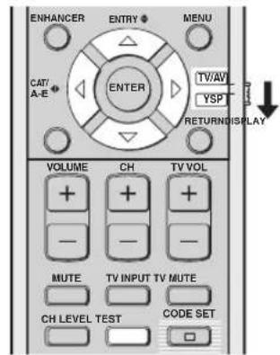
(U.S.A. and Canada models)
1 Set the operation mode selector to YSP.
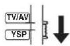
2 Press TEST.
"TEST FRONT L" appears in the front panel display and a test tone is output from the front left channel.
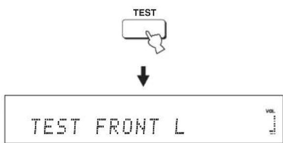
flowchart
graph TD
    A["TEST"] --> B["↓"]
    B --> C["TEST FRONT L"]
3 Press / △ to select the channel you want to adjust.
The front panel display changes as follows:
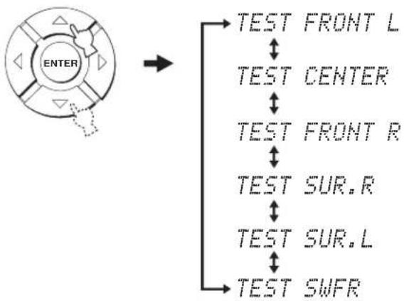
flowchart
graph TD
    A["ENTER"] --> B["TEST FRONT L"]
    A --> C["TEST CENTER"]
    A --> D["TEST FRONT R"]
    A --> E["TEST SUR.R"]
    A --> F["TEST SUR.L"]
    A --> G["TEST SWFR"]
Note
"TEST SWFR" is only available when a subwoofer is connected to this unit and SWFR is selected for BASS OUT in SOUND MENU (see page 78).
4 Press / ◀to ▶adjust the channel volume.
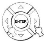
Control range: -10.0 dB to +10.0 dB
5 Press TEST when you have completed all your adjustments.

Notes
- All channel levels cannot be adjusted when the 2-channel or 5-channel stereo playback (see page 60), My Beam (see page 61), or My Surround (see page 55) is selected as the beam mode.
- "FRONT L/R" cannot be adjusted when Stereo plus 3 Beam is selected as the beam mode (see page 55).
- "FRONT L/R" are automatically adjusted depending on the settings of the other channels when Stereo plus 3 Beam or stereo playback is selected as the beam mode (see pages 55 and 60).

If the level of a particular channel cannot be adjusted, “-dB” appears in the front panel display.
Using the audio output being played back
You can also manually adjust the channel levels while playing back an input source such as a DVD.
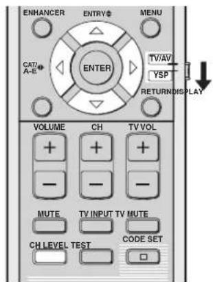
(U.S.A. and Canada models)
1 Set the operation mode selector to YSP.
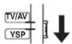
2 Press CH LEVEL repeatedly (or press CH LEVEL and △) to select the channel you want to adjust.
The front panel display changes as follows.
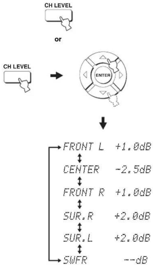
flowchart
graph TD
    A["CH LEVEL"] --> B["OR"]
    C["CH LEVEL"] --> B
    B --> D["ENTER"]
    D --> E["FRONT L +1.0dB"]
    D --> F["CENTER -2.5dB"]
    D --> G["FRONT R +1.0dB"]
    G --> H["SUR.R +2.0dB"]
    G --> I["SUR.L +2.0dB"]
    G --> J["SWFR --dB"]
Note
"SWFR" is available only when a subwoofer is connected to this unit and SWFR is selected for BASS OUT in SOUND MENU (see page 78).
3 Press / ◀ to ▶ adjust the channel volume.
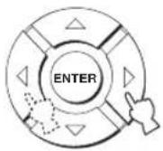
Control range: -10.0 dB to +10.0 dB
4 Wait for a few seconds without operating this unit when you have completed your adjustment.
Notes
- All channel levels cannot be adjusted when the 2-channel or 5-channel stereo playback (see page 60), or My Surround (see page 55) is selected as the beam mode.
- “FRONT L/R” cannot be adjusted when Stereo plus 3 Beam is selected as the beam mode (see page 55).
- Only CENTER can be adjusted when My Beam is selected as the beam mode (see page 61).
- "FRONT L/R" are automatically adjusted depending on the settings of the other channels when Stereo plus 3 Beam or stereo playback is selected as the beam mode (see pages 55 and 60).

If the level of a particular channel cannot be adjusted, “-dB” appears in the front panel display.
Selecting the input mode
You can select the type of audio input signals of the selected input source according to your preference or the conditions of the input source. This function is available for TV/STB, DVD, AUX1, and AUX2.

We recommend setting the input mode to AUTO in most cases.
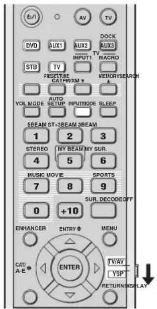
(U.S.A. and Canada models)
1 Set the operation mode selector to YSP.
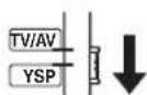
2 Press one of the input selector buttons to select the desired input source.
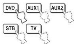
3 Press INPUTMODE repeatedly to toggle between input modes.
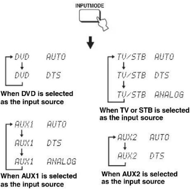
flowchart
graph TD
    A["INPUTMODE"] --> B["When DVD is selected as the input source"]
    B --> C["DVD"]
    C --> D["DVD"]
    D --> E["AUTO"]
    D --> F["DTS"]
    B --> G["When AUX1 is selected as the input source"]
    G --> H["AUX1"]
    H --> I["AUX1"]
    I --> J["AUTO"]
    I --> K["DTS"]
    G --> L["When AUX2 is selected as the input source"]
    L --> M["AUX2"]
    M --> N["AUX2"]
    N --> O["AUTO"]
    N --> P["DTS"]
    B --> Q["When TV or STB is selected as the input source"]
    Q --> R["TV/STB"]
    R --> S["AUTO"]
    R --> T["TV/STB"]
    T --> U["DTS"]
    R --> V["TV/STB"]
    V --> W["ANALOG"]
Note
ANALOG is not available as the input mode of DVD and AUX2.
• AUTO
Automatically selects audio input signals in the following priority order:
Use this input mode in most cases.
• DTS
Selects only digital signals encoded in DTS.
Compared to AUTO, this input mode provides greater stability while playing back CDs or LDs encoded in DTS.
• ANALOG
Selects only analog signals.
Even when both digital and analog signals are input simultaneously, only analog signals are selected.

You can adjust the default input mode to be selected when the power of this unit is turned on by adjusting INPUT MODE in INPUT MENU (see page 80).
Adjusting the system parameters
This unit has additional menus that are displayed in the front panel display. These menus offer additional operations to adjust and customize the way this unit operates.
Note
When "F.PANEL KEY" is set to "F.PANEL: OFF" (see page 93), STANDBY/ON on the front panel is ineffective. Use STANDBY/ON on the remote control instead to adjust the system parameters.
Using the system parameters
Follow the procedure below to enter the system parameters.
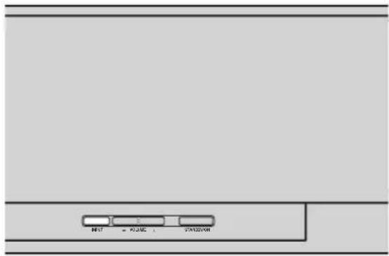
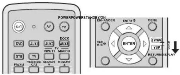
(U.S.A. and Canada models)
2 Press and hold INPUT on the front panel and press STANDBY/ON on the remote control to turn on the power of this unit.
"MEMORY PROTECT" is displayed in the front panel display.
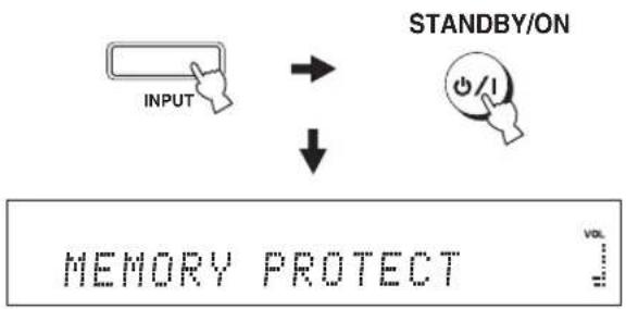
flowchart
graph TD
    A["INPUT"] --> B["STANDBY/ON"]
    B --> C["↓"]
    C --> D["MEMORY PROTECT"]
3 Release INPUT on the front panel.

1 Press STANDBY/ON on the remote control to turn off the power of this unit.
STANDBY/ON

Setting the MEMORY PROTECT
You can protect the settings you saved in the system memory of this unit from being accidentally erased or unwantedly changed.
1 Repeat steps 1 to 3 in "Using the system parameters" on page 88.
2 Set the operation mode selector to YSP.
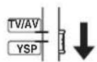
3 Confirm that "MEMORY PROTECT" is displayed in the front panel display and press ENTER.
MEMORY PROTECT

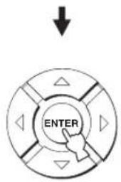
4 Press /to switch between "PROTECT: ON" and "PROTECT: OFF".


PROTECT: ON


PROTECT: OFF

- Select PROTECT: ON to activate the protection feature.
- Select PROTECT: OFF to deactivate the protection feature.
5 Press STANDBY/ON on the remote control to set this unit to the standby mode.
STANDBY/ON

The new setting will be activated when you turn on the power of this unit next time.
Setting the MAX VOLUME
You can set the maximum volume level so that this unit will not output sound beyond the limited volume level.
1 Repeat steps 1 to 3 in "Using the system parameters" on page 88.
2 Set the operation mode selector to YSP.
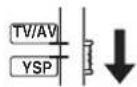
3 Press / so that "MAX VOLUME SET" is displayed in the front panel display.
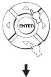
MAX VOLUME SET
4 Press ENTER.

5 Press / ◀to>adjust the maximum volume level.
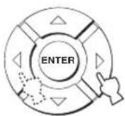
Control range: MAX, 99 to 01, MIN Control step: 1
6 Press STANDBY/ON on the remote control to set this unit to the standby mode.
STANDBY/ON

The new setting for the maximum volume level will be activated when you turn on the power of this unit next time.
Setting the TURN ON VOLUME
You can set the initial volume level when the power of this unit is turned on.
1 Repeat steps 1 to 3 in "Using the system parameters" on page 88.
2 Set the operation mode selector to YSP.
3 Press / so that "TURN ON VOLUME" is displayed in the front panel display.
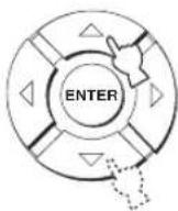
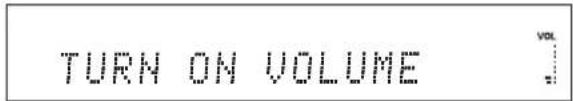
4 Press ENTER.

5 Press /◀to▶adjust the initial volume level.
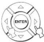
Control range: MAX, 99 to 01, OFF Control step: 1
6 Press STANDBY/ON on the remote control to set this unit to the standby mode.
STANDBY/ON

The new setting for the maximum volume level will be activated when you turn on the power of this unit next time.
Setting the DEMO MODE
You can test the sound beam output from this unit to experience the sound beam.
1 Repeat steps 1 to 3 in "Using the system parameters" on page 88.
2 Set the operation mode selector to YSP.
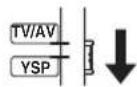
3 Press / so that "DEMO MODE" is displayed in the front panel display.
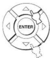
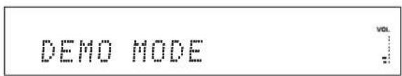
4 Press /to switch between "DEMO: ON" and "DEMO: OFF".


DEMO: ON


DEMO: OFF

- Select DEMO: ON to activate the demo mode.
- Select DEMO: OFF to deactivate the demo mode.
5 Press STANDBY/ON on the remote control to set this unit to the standby mode.
STANDBY/ON

The new setting will be activated when you turn on the power of this unit next time.
Press ENTER while playing back sources to test the sound beam.
The sound beam being output shuttles between left and right. Press ENTER again to stop shuttling.
Setting the PANEL INPUT KEY
You can disable the INPUT on the front panel when you adjust the system parameters.
1 Repeat steps 1 to 3 in "Using the system parameters" on page 88.
2 Set the operation mode selector to YSP.
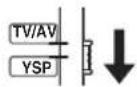
3 Press / so that "PANEL INPUT KEY" is displayed in the front panel display.


PANEL INPUT KEY

4 Press / ◀to switch between "P.INPUT: ON" and "P.INPUT: OFF".
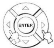

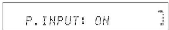

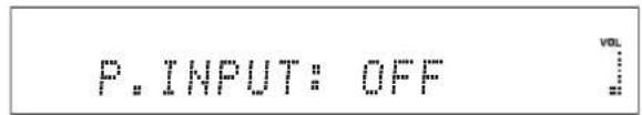
- Select P. INPUT: ON to enable the INPUT key on the front panel.
- Select P.INPUT: OFF to disable the INPUT key on the front panel. "F.PANEL KEY" is automatically set to "ON".
5 Press STANDBY/ON on the remote control to set this unit to the standby mode.
STANDBY/ON

The new setting will be activated when you turn on the power of this unit next time.
Disabling the front panel keys
You can disable the front panel keys except when you adjust the system parameters.
1 Repeat steps 1 to 3 in "Using the system parameters" on page 88.
2 Set the operation mode selector to YSP.
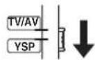
3 Press / so that "F.PANEL KEY" is displayed in the front panel display.
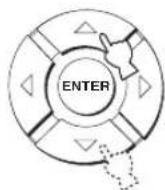

F.PANEL KEY

4 Press /to switch between "F.PANEL: ON" and "F.PANEL: OFF".
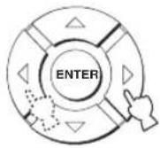

F.PANEL: ON


F.PANEL: OFF

- Select F.PANEL: ON to enable the front panel keys.
- Select F.PANEL: OFF to disable the front panel keys. "P.INPUT" is automatically set to "ON".
5 Press STANDBY/ON on the remote control to set this unit to the standby mode.
STANDBY/ON

The new setting will be activated when you turn on the power of this unit next time.
Setting the FACTORY PRESET
You can reset all of the parameters of this unit to the factory presets. This procedure completely resets ALL the parameters in SET MENU.
Note
After performing the following procedure you must run AUTO SETUP again to match your surround sound environment.
1 Repeat steps 1 to 3 in "Using the system parameters" on page 88.
2 Set the operation mode selector to YSP.
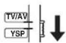
3 Press / so that "FACTORY PRESET" is displayed in the front panel display.

FACTORY PRESET

4 Press ENTER.

5 Press /to switch between "PRESET: RESET" and "PRESET: CANCEL".


PRESET: RESET


PRESET: CANCEL

- Select PRESET: RESET to reset all of the current settings.
- Select PRESET: CANCEL to cancel the resetting procedure.
6 Press STANDBY/ON on the remote control to set this unit to the standby mode.
STANDBY/ON

The new setting will be activated when you turn on the power of this unit next time.
Remote control features
In addition to controlling this unit, the remote control can also operate other AV components made by Yamaha and other manufacturers. To control other components, you must set up the remote control with the appropriate remote control codes and set the operation mode selector to TV/AV to change the control area.
Note
Depending on the external AV component you are using, you may not be able to operate the component with the remote control, even if a remote control code is set. In this case, operate the component using the supplied remote control.
Setting remote control codes
You can control other components by setting the appropriate remote control codes. Codes can be set up for each input area (DVD, AUX1, AUX2, STB, and TV).
For a complete list of available remote control codes, refer to "List of remote control codes" at the end of this manual.
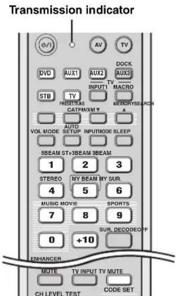
(U.S.A. and Canada models)
1 Press and hold CODE SET and press one of the input selector buttons to select the input source you want to set a remote control code for.
The transmission indicator flashes twice and remains lit.
Proceed to step 2 while holding down CODE SET.
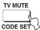
While holding down, press
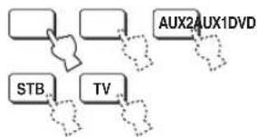
flowchart
graph TD
    A[" "] --> B["AUX2AUX1DVD"]
    C["STB"] --> D["TV"]
    E[" "] --> F[" "]
    G[" "] --> H[" "]
    I[" "] --> J[" "]
2 Press the numeric buttons to enter the remote control code while holding down CODE SET.
Setting example: Yamaha DVD input area
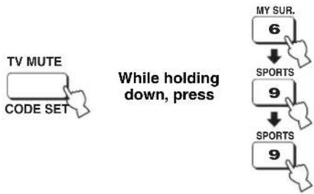
flowchart
graph TD
    A["TV MUTE CODE SET"] --> B["While holding down, press"]
    B --> C["MY SUR. 6"]
    C --> D["SPORTS 9"]
    D --> E["SPORTS 9"]
3 Refer to "Controlling other components" on page 97 to operate the external component using the remote control.
If the external component functions correctly the remote control code setup is successful.
If the external component does not function correctly, the remote control code may be incorrect. Confirm that the remote control code is correct. See "List of remote control codes" at the end of this manual and start over from step 1.
Note
If the manufacturer of your component has more than one code, try each of them until you find the correct one.
If the remote control is without batteries for more than two minutes, or if exhausted batteries remain in the remote control, the contents of the memory may be cleared. When the memory is cleared, insert new batteries and reset the remote control codes.
When changing the batteries, be careful not to press any of the buttons on the remote control. Doing so will clear the contents of the memory.
Controlling other components
■ Operating your TV
Set the operation mode selector to TV/AV, and press TV to select TV as the input source.
The control area of the remote control changes to the TV operation mode.
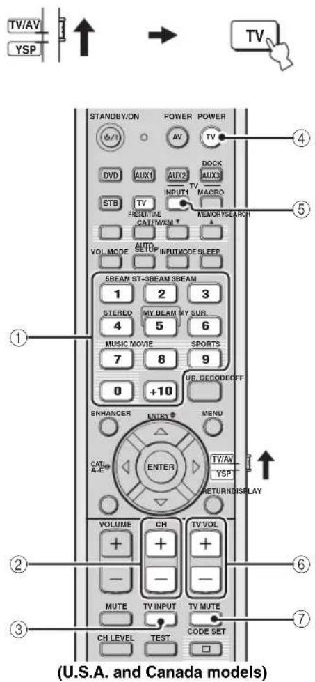
①Numeric buttons
Selects a TV channel for playback.
②CH+/-
Switches between the available TV channels.
③TV INPUT
Switches the input source for your TV.
④ TV POWER
Turns on or off the power of your TV.
⑤TV INPUT1
Selects the input source of your TV.
⑥TV VOL +/-
Adjusts the audio output level of your TV.
⑦ TV MUTE
Temporarily mutes audio output from your TV.
■ Operating your DVD player/recorder
Set the operation mode selector to TV/AV and press DVD to select DVD as the input source.
The control area of the remote control changes to the DVD operation mode.
![TV/AV YSP ↑ → DVD STANDBY/ON POWER POWER ④ DVDC AUX1 AUX2 AUTO STB TV INPUT1 TV MACRO PRESETURE MEMORYSEARCH CAT/NXM+ VOL MODE AUTO SETUP INPUTMODE SLEEP 5BEAM ST+3BEAM 3BEAM 1 2 3 STEREO MY BEAM MY SUR. 4 5 6 MUSIC MOVIE SPORTS 7 8 9 0 +10 SUR. DECODEOFF ENHANCER ENTRY MENU CAT/A-E ENTER TV/AV YSP RETURNOISPLAY VOLUME CH TV VOL + + - - MUTE TV INPUT TV MUTE CH LEVEL TEST CODE SET < > [ ] [ > ] [ > ] [ > ]](/content/2026/02/375754/images/c26478aca29f89638f2b7cbfd8656168af910a481e3cd5815a4b03c08ed42256.jpg)
(U.S.A. and Canada models)
①Numeric buttons
Enter numeric digits.
②Cursor buttons ↗, ENTER
Use to select DVD menu items.
③Operation buttons for DVD players
Operate your DVD player/recorder, such as play and stop.
④AV POWER
Turns on or off the power of your DVD player/recorder.
⑤MENU
Displays the DVD menu.
⑥RETURN
Use to return to the previous DVD menu screen or exit from the DVD menu.
■ Operating your STB (CATV/Satellite tuner)
Set the operation mode selector to TV/AV and press STB to select STB as the input source.
The control area of the remote control changes to the STB operation mode.
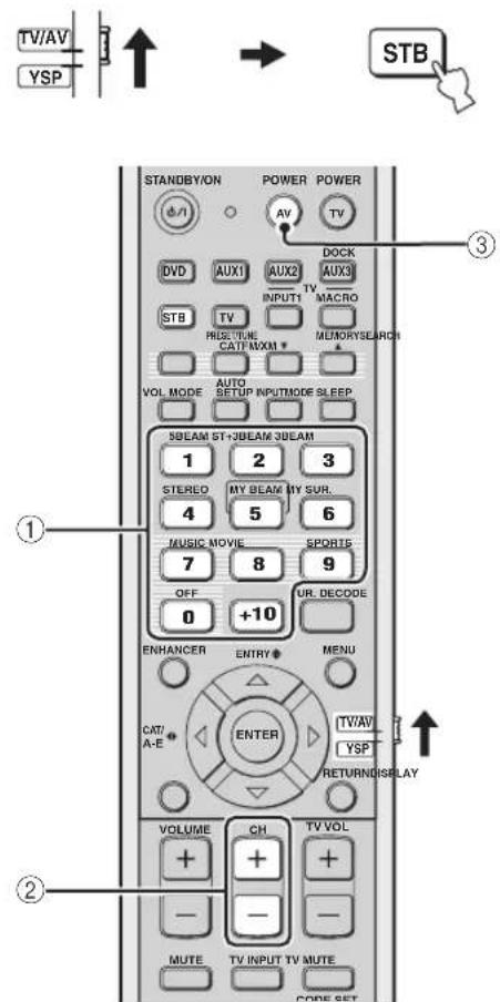
(U.S.A. and Canada models)
①Numeric buttons
Enter numeric digits.
②CH+/-
Switches between the available STB channels.
③AV POWER
Turns on or off the power of your STB.
■ Operating your VCR
Set the operation mode selector to TV/AV and press AUX1 to select VCR as the input source.
The control area of the remote control changes to the AUX1 operation mode.

This operation is available when your VCR is connected to the AUX 1 AUDIO INPUT jacks on this unit.
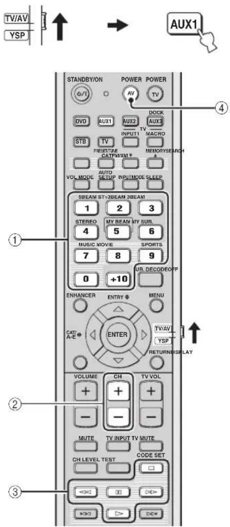
(U.S.A. and Canada models)
①Numeric buttons
Enter numeric digits.
②CH+/-
Switches between the available VCR channels.
③Operation buttons for VCR
Operate your VCR, such as play and stop.
④AV POWER
Turns on or off the power of your VCR.
Using the TV macro
The TV macro feature makes it possible to perform a series of operations with the press of a single button. For example, when you want to play a DVD, you would normally turn on the component, select DVD as the input source, and press the play button to start playback. The TV macro feature lets you perform all of these operations simply by pressing the DVD macro button.
Notes
- Be sure to set up a remote control code for your TV before setting macros.
- The ways to set macros differ if your TV does not have the tuning capability.
- If you press any control buttons on the remote control other than the ones used to set macros while setting macros, the setting procedure is automatically canceled.
- If it takes more than 10 seconds in steps 2 and 3, the setting procedure is automatically canceled. In this case, repeat from step 1.
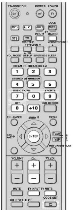
(U.S.A. and Canada models)
■ Setting macros for the TV with the tuning capability
1 Press and hold CODE SET and press one of the input selector buttons to select the input source you want to set macros for.
Proceed to step 2 while holding down CODE SET.
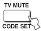
While holding down, press
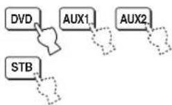
2 Press MACRO while holding down CODE SET.
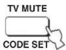
While holding down, press

3 Press CH +/- or the numeric buttons to select the TV channel.
Check that the TV screen changes to the tuner screen.

or
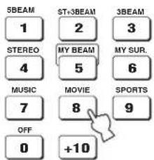
4 Press TV INPUT repeatedly until the screen changes to the display of the input source selected in step 1.
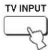
5 Press ENTER to confirm the macro setting.

■ Setting macros for the TV without the tuning capability
1 Press and hold CODE SET and press one of the input selector buttons to select the input source you want to set macros for.
Proceed to step 2 while holding down CODE SET.
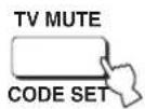
While holding down, press
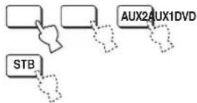
flowchart
graph TD
    A[" "] --> B[" "]
    B --> C["AUX2AUX1DVD"]
    D["STB"] -.-> C
2 Press MACRO while holding down CODE SET.
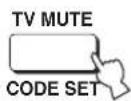
While holding down, press

3 Press INPUT1.
Check that the TV screen changes to the input 1 screen.
4 Press TV INPUT repeatedly until the screen changes to the display of the input source selected in step 1.
5 Press ENTER to confirm the setting.

■ Operating macros
Press and hold one of the input selector buttons for approximately two seconds to select the input source you want to operate macros for.
The TV input changes at the same time the input mode changes.
flowchart
graph TD
    A[" "] --> B[" "]
    B --> C["AUX2AUX1DVD"]
    C --> D["STB"]
■ Canceling the macros
1 Press and hold CODE SET and press one of the input selector buttons to select the input source you want to cancel the macros for.
Proceed to step 2 while holding down CODE SET.
While holding down, press
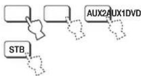
flowchart
graph TD
    A[" "] --> B[" "]
    B --> C["AUX2AUX1DVD"]
    D["STB"] --> E["..."]
2 Press MACRO while holding down CODE SET.
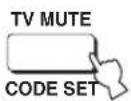
While holding down, press

3 Press ENTER to cancel the macros.

Troubleshooting
Refer to the chart below when this unit does not function properly. If the problem you are experiencing is not listed below or if the instruction below does not help, set this unit to the standby mode, disconnect the AC power supply cable, and contact the nearest authorized Yamaha dealer or service center.
■ General
| Problem Cause Remedy | See page | ||
| This unit fails to turn on when STANDBY/ON is pressed, or enters the standby mode soon after the power has been turned on. | The AC power supply cable is not firmly connected to the AC wall outlet. | Connect the AC power supply cable firmly to the AC wall outlet. | 29 |
| This unit has been exposed to a strong external electric shock (such as lightning and strong static electricity). | Set this unit to the standby mode, disconnect the AC power supply cable, plug it back in after 30 seconds, and use it normally. | — | |
| This unit suddenly enters the standby mode. | The internal temperature becomes too high and the overheat protection circuitry has been activated. | Wait for about one hour for this unit to cool down and turn it back on. | — |
| The sleep timer has turned the unit off. Turn on the power and play back the source again. | — | ||
| No sound. | Incorrect input or output cable connections. | Connect the cables properly. If the problem persists, the cables may be defective. | 19 |
| No appropriate input source has been selected. | Select an appropriate input source with INPUT or the input selector buttons. | 45 | |
| The volume is turned down. Turn up the volume. | 47 | ||
| The sound is muted. Press MUTE or VOLUME +/- to resume audio output and adjust the volume level. | 47 | ||
| The signals this unit cannot reproduce (such as PCM signals with more than 96 kHz of sampling frequency) are being received from the source component. | Play a source whose signals can be reproduced by this unit. | — | |
| Change the system settings of the source component. | — | ||
| The HDMI components connected to this unit do not support the HDCP copy protection standards. | Connect the HDMI components that support the HDCP copy protection standards. | 20 | |
| SUPPORT AUDIO is set to OTHER and HDMI audio signals are not being played back on this unit. | Set SUPPORT AUDIO to HTY-7030 in MANUAL SETUP | 82 | |
| The sound suddenly goes off. | The sleep timer has turned this unit off. Turn on the power and play back the source again. | — | |
| The sound is muted. Press MUTE or VOLUME +/- to resume audio output and adjust the volume level. | 47 | ||
| No sound from the effect channels. | You are playing back the source or program in the 2-channel stereo playback or My Beam mode. | Press one of the beam mode buttons on the remote control to select a multi-channel playback mode and play back the source or program once more. | 54 |
| No sound from the center channel. | The output level of the center channel is set to minimum. | Raise the level of the center channel. | 84 |
| No sound from the surround channels. | The output level of the surround channels is set to minimum. | Raise the output level of the surround channels. | 84 |
| Problem Cause Remedy | See page | ||
| No sound from the subwoofer. | BASS OUT in SUBWOOFER SET is set to FRONT. | Select SWFR. | 78 |
| The source does not contain low bass signals. | |||
| Distorted or too little bass sound. | CROSS OVER in SUBWOOFER SET is set incorrectly. | Set CROSS OVER correctly. | 78 |
| One of the night listening enhancers is currently selected. | Turn off the night listening enhancers. | 67 | |
| Too much bass sound. TruBass is currently turned on. Turn off TruBass. | 79 | ||
| Turn down the volume level of the subwoofer. | — | ||
| Surround sound effects are insubstantial. | The listening room is not a regular shape. Install this unit in a square or rectangular shaped room. | — | |
| There is no wall in the path of the sound beam. | Try placing a flat object, such as a board, in the path of the sound beam. | — | |
| Dolby Digital or DTS sources cannot be played back.(Dolby Digital or DTS indicator does not light up in the front panel display.) | The connected component is not set to output Dolby Digital or DTS digital signals. | Make an appropriate setting following the operating instructions for your component. | — |
| The input mode is set to ANALOG. Set the input mode to AUTO. | 87 | ||
| There is noise interference when a subwoofer is not connected to this unit. | The protection circuitry was in operation because a source with strong bass elements was played back. | Turn down the volume level. | 47 |
| Select SWFR for BASS OUT. | 78 | ||
| Connect a subwoofer and adjust settings for SUBWOOFER SET. | 78 | ||
| Low-frequency sounds are distorted. | CROSS OVER in SUBWOOFER SET is set incorrectly. | Set CROSS OVER correctly. | 78 |
| On-screen display does not appear. | The OSD video pin cable is not connected properly. | Connect the cable properly. | 22 |
| This unit does not operate properly. | The internal microcomputer has been frozen by an external electric shock (such as lightning or excessive static electricity) or by a power supply with low voltage. | Disconnect the AC power supply cable from the outlet and plug it in again after about 30 seconds. | — |
| No sound is heard from the TV connected via HDMI. | The TV does not accept the multi-channel audio signals. | Convert the multi-channel audio signals to the 2-channel audio signals at the source component such as a DVD player. | — |
| “SUPPORT AUDIO” is set to “HTY-7030”. Set “SUPPORT AUDIO” to “OTHER”. | 82 | ||
| There is noise interference from digital or high-frequency equipment. | This unit is too close to the digital or high-frequency equipment. | Move this unit farther away from such equipment. | — |
| This unit does not output effect sounds properly. | The original source includes surround effects. | Disable the surround effect settings of this unit. | — |
| My Beam auto-adjust function does not work. | The listening room is too noisy. Keep the listening room as quiet as possible. | — | |
| 62 | |||
| The sound reflectivity of the listening room is too much. | Set REFLECTING to HI ECHO. | 79 | |
| The remote control may be operated outside of the remote control operation range. | The remote control functions within a maximum range of 6 m (20 ft) and no more than 45 degrees off-axis from the front panel. | 30 | |
| The function does not work properly because of the condition of the connected components. | Select My Beam and then try again. | 61 | |
■ Remote control
| Problem Cause Remedy | See page | ||
| The remote control does not work and/or function properly. | Wrong distance or angle. The remote control functions within a maximum range of 6 m (20 ft) and no more than 45 degrees off-axis from the front panel. | 30 | |
| Direct sunlight or lighting (from an inverter type of fluorescent lamp, etc.) is striking the remote control sensor of this unit. | Reposition this unit. | — | |
| The batteries are weak. Replace all batteries. | 30 | ||
| Cannot operate external components with the remote control of this unit. | The external component you want to operate is not selected as the input source. | Press INPUT on the front panel or the input selector buttons on the remote control to select the external component you want to operate. | 45 |
| The remote control code was not correctly set. | Set the remote control code correctly or try another code for the same manufacturer using the “List of remote control codes” at the end of this manual. | 96 | |
| Even if the remote control code is correctly set, there are some models that do not respond to the remote control. | Use the remote control supplied with the external component. | — | |
| The cursor buttons do not work during SET MENU operation. | The operation mode selector was unwantedly set to TV/AV. | Set the operation mode selector to YSP. | — |
| Cannot use the My Beam auto-adjust function. | Wrong distance or angle. The remote control functions within a maximum range of 6 m (20 ft) and no more than 45 degrees off-axis from the front panel. | 30 | |
HDMI
| Error message Cause | Remedy | See page | |
| Device Error The number of the connected HDMI components exceeds the limit. | Reduce the number of the connected HDMI components. | — | |
| HDCP Error HDCP authentication failed. Check that the connected HDMI components support the HDCP copy protection standards. | — | ||
■ FM tuner
| Problem Cause Remedy | See page | ||
| FM stereo reception is noisy. | The characteristics of FM stereo broadcasts may cause this problem when the transmitter is too far away or the antenna input is poor. | Check the antenna connections. | 29 |
| Try using a high-quality directional FM antenna. | — | ||
| Use the manual tuning method. | 49 | ||
| There is distortion, and clear reception cannot be obtained even with a good FM antenna. | There is multi-path interference. Adjust the antenna position to eliminate multi-path interference. | — | |
| The desired station cannot be tuned into with the automatic tuning method. | The signal is too weak. Use a high-quality directional FM antenna. | — | |
| 49 | |||
| Previously preset stations can no longer be tuned into. | This unit has been disconnected for a long period. | Preset the stations again. | 50 |
Glossary
■ Dolby Digital
Dolby Digital is a digital surround sound system that gives you completely independent multi-channel audio. With 3 front channels (left, center, and right) and 2 surround stereo channels, Dolby Digital provides 5 full-range audio channels. With an additional channel especially for bass effects, called LFE (low-frequency effect), the system has a total of 5.1-channels (LFE is counted as 0.1-channel). By using 2-channel stereo for the surround channels, more accurate moving sound effects and surround sound environment are possible than with Dolby Surround. The wide dynamic range (from maximum to minimum volume) reproduced by the 5 full-range channels and the precise sound orientation generated using digital sound processing provide listeners with excitement and realism previously unheard of.
With this unit, any sound environment from monaural up to a 5.1-channel configuration can be freely selected for your enjoyment.
■ Dolby Pro Logic II
Dolby Pro Logic II is an improved technique used to decode vast numbers of existing Dolby Surround software. This new technology enables a discrete 5-channel playback with 2 front left and right channels, 1 center channel, and 2 surround left and right channels (instead of only 1 surround channel for conventional Pro Logic technology). Music and Game modes are also available for 2-channel sources in addition to the Movie mode.
■ Dolby Surround
Dolby Surround uses a 4-channel analog recording system to reproduce realistic and dynamic sound effects: 2 front left and right channels (stereo), a center channel for dialog (monaural), and a surround channel for special sound effects (monaural). The surround channel reproduces sound within a narrow frequency range. Dolby Surround is widely used with nearly all video tapes and laser discs, and in many TV and cable broadcasts as well. The Dolby Pro Logic decoder built into this unit employs a digital signal processing system that automatically stabilizes the volume on each channel to enhance moving sound effects and directionality.
■ DTS Digital Surround
DTS digital surround was developed to replace the analog soundtracks of movies with a 6-channel digital sound track, and is now rapidly gaining popularity in movie theaters around the world. DTS, Inc. has developed a home theater system so that you can enjoy the depth of sound and natural spatial representation of DTS digital surround in your home. This system produces practically distortion-free 6-channel sound (technically, left, right, and center channels, 2 surround channels, plus an LFE 0.1-channel as a subwoofer, for a total of 5.1 channels). The unit incorporates a DTS-ES decoder that enables 6.1-channel reproduction by adding the surround back channel to existing 5.1-channel format.
■ DTS Neo:6
Neo:6 decodes the conventional 2-channel sources for 6-channel playback by the specific decoder. It enables playback with the full-range channels with higher separation just like digital discrete signal playback. Two modes are available: Music mode for playing music sources and Cinema mode for movies.
EUPHONY
Euphony is a revolutionary sound field reproduction system implemented with state-of-the-art sound technologies developed under the basic concept of enjoying beautiful sound. It can reproduce surround sound optimized without depending on the number of input channels, the number of speakers (two or more speakers) or the speaker's dimensions. In addition, it features steady center localization. It also can reproduce the surround sound for the headphones with natural sound and "out-of-head" localization so that the listener feels an expanded sound and will not tire, even when listening to music or a movie for long time.
HDMI
HDMI (High-Definition Multimedia Interface) is the first industry-supported, uncompressed, all-digital audio/video interface. Providing an interface between any source (such as a set-top box or AV receiver) and an audio/video monitor (such as a digital television), HDMI supports standard, enhanced, or high-definition video as well as multi-channel digital audio using a single cable. HDMI transmits all ATSC HDTV standards and supports 8-channel digital audio, with bandwidth to spare to accommodate future enhancements and requirements. When used in combination with HDCP (High-bandwidth Digital Content Protection), HDMI provides a secure audio/video interface that meets the security requirements of content providers and system operators. For further information on HDMI, visit the HDMI website at "http://www.hdmi.org/".
■ LFE 0.1-channel
This channel is for the reproduction of low bass signals. The frequency range for this channel is 20 Hz to 120 Hz. This channel is counted as 0.1 because it only enforces a low-frequency range compared to the full-range reproduction by the other 5/6 channels in Dolby Digital or DTS 5.1/6.1-channel systems.
■ Neural Surround
Neural Surround ^™ represents the latest advancement in surround technology and has been adopted by XM Satellite Radio for digital radio broadcast of surround recordings and live events in surround sound. Neural Surround ^™ employs psychoacoustic frequency domain processing which allows delivery of a more detailed sound stage with superior channel separation and localization of audio elements.
■ PCM (Linear PCM)
Linear PCM is a signal format under which an analog audio signal is digitized, recorded, and transmitted without using any compression. This is used as a method of recording CDs and DVD audio. The PCM system uses a technique for sampling the size of the analog signal per very small unit of time. Standing for pulse code modulation, the analog signal is encoded as pulses and then modulated for recording.
■ SRS TruBass
SRS TruBass is a psychoacoustic bass enhancement technology developed by SRS Labs, Inc. for speakers and headphone systems that delivers bass up to an octave below the physical capabilities of the speaker's driver. SRS TruBass technology takes advantage of a spontaneous tendency of the human ears to infer low-range audio data when presented with higher-frequency harmonic signals. As a result, our ears can hear the original low-range sound that the speaker system is incapable of producing.
Index
■ Numerics
3 Beam....55
5 Beam.... 54
A
AC power supply cable.... 29
Audio pin cable.... 20
AUTO SETUP (IntelliBeam)....35
B
Battery....30
BEAM MENU 74
Beam mode ....54, 60, 61
C
Cable clamp 20
Cardboard microphone stand....37
CINEMA DSP 64
D
DEMO MODE....91
Demonstration DVD....6
Digital audio pin cable.... 20
DISPLAY MENU....83
Dolby Digital 56
Dolby Pro Logic....56
Dolby Pro Logic II....56
DTS....56
DTS Neo: 6 56
Dynamic range....79
■E
EUPHONY 105
F
FACTORY PRESET 94
Fastener....18
Front panel....7
Front panel display 8
■ H
HDMI....20
HDMI cable 20
■
IntelliBeam 35
IntelliBeam microphone 36
■L
LFE 0.1-channel .... 106
■ M
MANUAL SETUP 72
MEMORY....42
Movie program....64
Music program 64
My Beam....61
■ N
Night listening enhancer 67
■ 0
On-screen display (OSD)....32
Optical cable ....20
OSD video pin cable 20
P
PCM 106
Power....31
■ R
Rear panel 9
Remote control....10
Remote control code 96
Remote control sensor....30
■S
SET MENU....32
Sleep timer 68
Sound field program....63
Stereo plus 3 Beam ....55
Surround mode....56
Surround sound 54
SOUND MENU 78
Sports program....64
Stereo sound....60
System parameter....88
■T
Test tone 84
TruBass....79
TV macro ....100
TV volume equal mode....67
■ v
Volume 47
Volume mode 67
Specifications
AMP SECTION
• Maximum Output Power (JEITA) 2 W (1 kHz, 10% THD, 4 Ω) × 21 20 W (100 Hz, 10% THD, 4 Ω) × 2
SPEAKER SECTION
- Driver Small dia. speakers .... 4 cm (1-9/16 in) cone magnetic shielding type × 21 Woofers .... 10 cm (3-15/16 in) cone magnetic shielding type × 2
• Frequency response....60 Hz to 20 kHz (-10 dB, stereo mode)
CONNECTIONS
- Input Jacks TV/STB, AUX 1 AUDIO IN (1 V, 32 kΩ) .....2 pairs (Analog) TV/STB, AUX 1 OPTICAL DIGITAL IN .....2 (Optical digital) DVD, AUX 2 COAXIAL DIGITAL IN .....2 (Coaxial digital) AUX 1, DVD HDMI IN .....2 AUX 3 .....1
- Output Jacks SUBWOOFER OUT (1.5 V, less than 120 Hz) .....1 (Subwoofer) VIDEO OUT (1 Vp-p, 75 Ω) .....1 (OSD) HDMI OUT .....1
- System Connector Jack INTELLIBEAM MIC ....1 (Microphone input)
HDMI interface of this unit is based on the following standard:
- HDCP (High-bandwidth Digital Content Protection System) licensed by Digital Content Protection, LLC.
FM SECTION
- Tuning Range [U.S.A. and Canada models] 87.5 to 107.9 MHz [Asia model] 87.5/87.50 to 108.0/108.00 MHz [Other models] 87.50 to 108.00 MHz
GENERAL
• Power Supply [U.S.A. and Canada models] ..... AC 120 V, 60 Hz [Australia model] ..... AC 220–240 V, 50/60 Hz [U.K. and Europe models] ..... AC 220–240 V, 50/60 Hz [Korea model] ..... AC 220–240 V, 50/60 Hz [General model] ..... AC 110–120 V, 50/60 Hz [Asia model] ..... AC 220–240 V, 50/60 Hz
• Power Consumption ....32 W
- Standby Power Consumption .... 0.5 W or less
- Dimensions (W x H x D) 800 × 155 × 152 mm
(31-1/2 x 6-3/32 x 5-31/32 in)
• Weight 11.5 kg (25 lbs 6 oz)
* Specifications are subject to change without notice.
Limited Guarantee for European Economic Area (EEA) and Switzerland
Thank you for having chosen a Yamaha product. In the unlikely event that your Yamaha product needs guarantee service, please contact the dealer from whom it was purchased. If you experience any difficulty, please contact Yamaha representative office in your country. You can find full details on our website (http://www.yamaha-hifi.com/ or http://www.yamaha-uk.com/ for U.K. resident).
The product is guaranteed to be free from defects in workmanship or materials for a period of two years from the date of the original purchase. Yamaha undertakes, subject to the conditions listed below, to have the faulty product or any part(s) repaired, or replaced at Yamaha's discretion, without any charge for parts or labour. Yamaha reserves the right to replace a product with that of a similar kind and/or value and condition, where a model has been discontinued or is considered uneconomic to repair.
Conditions
- The original invoice or sales receipt (showing date of purchase, product code and dealer's name) MUST accompany the defective product, along with a statement detailing the fault. In the absence of this clear proof of purchase, Yamaha reserves the right to refuse to provide free of charge service and the product may be returned at the customer's expense.
- The product MUST have been purchased from an AUTHORISED Yamaha dealer within the European Economic Area (EEA) or Switzerland.
- The product must not have been the subject of any modifications or alterations, unless authorised in writing by Yamaha.
- The following are excluded from this guarantee:
a. Periodic maintenance and repair or replacement of parts due to normal wear and tear.
b. Damage resulting from:
(1) Repairs performed by the customer himself or by an unauthorised third party.
(2) Inadequate packaging or mishandling, when the product is in transit from the customer. Please note that it is the customer's responsibility to ensure the product is adequately packaged when returning the product for repair.
(3) Misuse, including but not limited to (a) failure to use the product for its normal purpose or in accordance with Yamaha's instructions on the proper use, maintenance and storage, and (b) installation or use of the product in a manner inconsistent with the technical or safety standards in force in the country where it is used.
(4) Accidents, lightning, water, fire, improper ventilation, battery leakage or any cause beyond Yamaha's control.
(5) Defects of the system into which this product is incorporated and/or incompatibility with third party products.
(6) Use of a product imported into the EEA and/or Switzerland, not by Yamaha, where that product does not conform to the technical or safety standards of the country of use and/or to the standard specification of a product sold by Yamaha in the EEA and/or Switzerland.
(7) Non AV (Audio Visual) related products. (Products subject to “Yamaha AV Guarantee Statement” are defined in our website at http://www.yamaha-hifi.com/ or http://www.yamaha-uk.com/ for U.K. resident.)
-
Where the guarantee differs between the country of purchase and the country of use of the product, the guarantee of the country of use shall apply.
-
Yamaha may not be held responsible for any losses or damages, whether direct, consequential or otherwise, save for the repair or replacement of the product.
-
Please backup any custom settings or data, as Yamaha may not be held responsible for any alteration or loss to such settings or data.
-
This guarantee does not affect the consumer's statutory rights under applicable national laws in force or the consumer's rights against the dealer arising from their sales/purchase contract.
AUTO SETUP (IntelliBeam) 35
Organigramme de AUTO SETUP 35
Installation du microphone IntelliBeam 36
Utilisation de AUTO SETUP (IntelliBeam).... 37
Corrections CINEMA DSP 64
AUTO SETUP (IntelliBeam)
Piles (×2)
(AA, R6, UM-3)

natural_image
Simple line drawing of a metal profile with a circular hole and two notches (no text or symbols)natural_image
Illustration of a coiled cable with two connectors, labeled (Orange) at the bottom (no other text or symbols)natural_image
Illustration of a bundle of four connectors with label (Blanc/Rouge) pointing to one end (no other text or symbols)natural_image
Illustration of a bundle of cables with two connectors, labeled (Jaune) at the bottom (no other text or symbols)③3 TV MUTE, CODE SET
flowchart
graph TD
    A["Rectangular Object"] --> B["Object with Arrow"]
    B --> C["Arrow Right"]
    C --> D["3D Object with Arrow"]
    D --> E["Arrow Left"]
    E --> F["3D Object with Arrow"]
    style A fill:#f9f,stroke:#333
    style D fill:#ccf,stroke:#333
Exemple 2
flowchart
graph TD
    A["Object Tracking"] --> B["Object Detection"]
    B --> C["Object Tracking with Object Recognition"]
    C --> D["Object Detection with Object Recognition"]
    D --> E["Object Tracking with Object Recognition"]
    E --> F["Object Detection with Object Recognition"]
    F --> G["Object Tracking with Object Recognition"]
    G --> H["Object Detection with Object Recognition"]
Exemple 3
flowchart
graph TD
    A["Hand gestures"] --> B["Arrow to central node"]
    B --> C["Arrow to right"]
    C --> D["Arrow to left"]
    D --> E["Arrow to right"]
    E --> F["Arrow to right"]
    F --> G["Arrow to right"]
    G --> H["Arrow to right"]
    H --> I["Arrow to right"]
    I --> J["Arrow to right"]
    J --> K["Arrow to right"]
    K --> L["Arrow to right"]
    L --> M["Arrow to right"]
    M --> N["Arrow to right"]
    N --> O["Arrow to right"]
    O --> P["Arrow to right"]
    P --> Q["Arrow to right"]
    Q --> R["Arrow to right"]
    R --> S["Arrow to right"]
    S --> T["Arrow to right"]
    T --> U["Arrow to right"]
    U --> V["Arrow to right"]
    V --> W["Arrow to right"]
    W --> X["Arrow to right"]
    X --> Y["Arrow to right"]
Installation
natural_image
Line drawing of a multi-tiered electronic device with monitor and tower base (no text or symbols)natural_image
Illustration of a remote control with a scroll wheel and mouse, showing no text or symbolsPush [MENU] to begin set-up
natural_image
Simple gray downward arrow symbol on white background (no text or labels)

En cas d'erreur
AUTO SETUP (IntelliBeam)
natural_image
Simple line drawing of a triangular container with a circular opening and an arrow pointing to a circular cross-section (no text or symbols)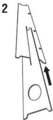
natural_image
Simple line drawing of a mechanical part with an arrow indicating direction (no text or symbols)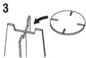
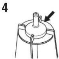
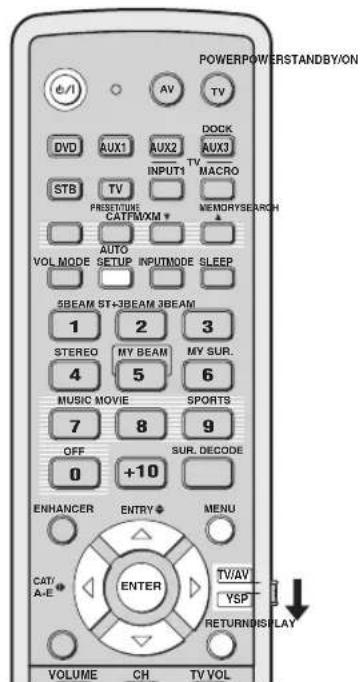
PREPARATION & CHECK Please connect the MIC. Please place the MIC at least 1.8m/6ft away from the YSP unit. The MIC should be set at ear level when seated. Measurement takes about 3min. After ENTER is pressed, please leave the room. ENTER: Start RETURN: Cancel
BEAM+SOUND OPTIMZ
Will begin in 10sec Please leave the room
Clignote
Exemple 2
![SHARESULT MEASUREMENTCOMPLETE ENVIRONMENTCHECK[FAILED] BEAMMODE:SBEAM SUBWOOFER:YES [ENTER]:Saveset-up. [RETURN]:Donotsaveset-up.](/content/2026/02/375754/images/5e63a6036a06d3db9d892b1c146523d84cd7fa87359c7d66af17b77b41a79749.jpg)
[Non-Text]
Your VSP unit may not be set up correctly. We recommend you try again.
Please press ENTER key to exit.
natural_image
Diagram of a device panel with ports and a hanging pipe, no text or symbols present![YAMAHA HTY7030 - [Non-Text] - 1](/content/2026/02/375754/images/6ecbe30a67308c1fa32af0df207668e4141294297bac35c0f2e6160891e32e76.jpg)
flowchart
graph TD
    A["Rectangular Box"] --> B["Leaf"]
    B --> C["Downward Arrow"]
    C --> D["Downward Arrow"]
The image contains a graphical symbol (a light bulb with radiating lines) and no textual content. Therefore, the correct OCR output is an empty string.
Remarque
natural_image
Simple diagram showing a horizontal bar above a downward arrow and a small plant icon below (no text or symbols)
flowchart
graph TD
    A["Start"] --> B{Decision}
    B --> C["Output Box with Leaf Icon"]
Corrections CINEMA DSP
flowchart
graph LR
    A["SLEEP"] --> B["..."]
    B --> C["SLEEP"]
    C --> D["Clignote"]
flowchart
graph TD
    A["SLEEP"] --> B["↓"]
    B --> C["SLEEP OFF"]
    C --> D["VOL"]
ou
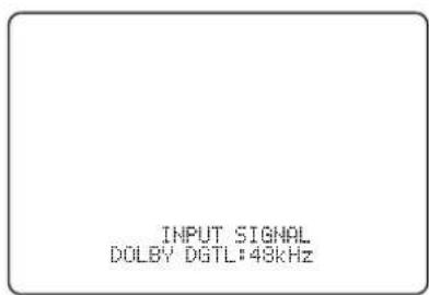
SET MENU → MANUAL SETUP → BEAM MENU
2.500
→ A) SETTING PARAMETERS B) BEAM ADJUSTMENT C) IMAGE LOCATION
[▲]/[▼]:Up/Down

natural_image
Blank white rectangular paper with a small rectangular top on the left side (no text or symbols)ANGLE TO WALL
OR CORNER

natural_image
Simple geometric shape: a diagonal line inside a square frame (no text or symbols)natural_image
Pure geometric diagram showing two rectangular shapes with dashed lines and arrows, no text or symbols presentTREBLE GAIN (Aigus)
flowchart
graph TD
    A["Rectangular Node"] --> B["Container with Leaf Icon"]
    B --> C["Vertical Line"]
SET MENU → MANUAL SETUP → SOUND MENU
![1) SOUND MENU → A) TONE CONTROL B) SUBWOOFER SET C) MUTE LEVEL D) AUDIO DELAY E) ROOM EQ F) DD/PTS Dynamic Range G) TrueBass [4]/[5]: Up/Down [ENTER]: Enter](/content/2026/02/375754/images/d9189917ed04d857f56cd840a7428924f83412d9cbed2286a795cd7010f4595d.jpg)
■ TONE CONTROL
MOUNTING (Type de montage)
■ DD/DTS Dynamic Range
Choix: MIN (minimum), STD (standard),
MAX (maximum)
100 1 10 00 100 100 100 100 100 100 100 1 1 1 1 1 1 1 1 1 1 1 1 1 1 1 1 1 1 1 1 1 1 1 1 1 1 1 1 1 1 1 1 1 1 1 1 1 1 1 1 1 1 1 1 1 1 1 1 1 1 1 1 1 1 1 1 1 1 1 1 1 1 1 1 1 1 1 1 1 1 1 1 1 1 1 1 1 1 1 1 1 1 1 1 1 1 1 1 1 1 1 1 1
MIN STD MAX
[¬0/ [¬]: Select
Remarque
SET MENU → MANUAL SETUP → INPUT MENU
![3) INPUT MENU → A) INPUT ASSIGNMENT B) INPUT MODE C) INPUT TRIM D) INPUT RENAME E) HDMI SET F) XM ANTENNA LEVEL [4]/[7]: Up/Down [ENTER]: Enter](/content/2026/02/375754/images/a6881b62b8555811e35ccca4967f4040126c9b65f7d67be213daa4dd88a711a3.jpg)
Remarque
SUPPORT AUDIO (Support audio)
XM ANTENNA LEVEL....97%
Remarque
SET MENU → MANUAL SETUP → DISPLAY MENU
4) DISPLAY MENU
+ B)E DISPLAY SET B)OSD SET C)UNIT SET
[▲]/[▼]:Up/Down
■ F.DISPLAY SET
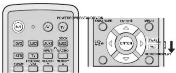
flowchart
graph TD
    A["INPUT"] --> B["STANDBY/ON"]
    B --> C["↓"]
    C --> D["MEMORY PROTECT VOL."]
flowchart
graph TD
    A[" "] --> B["AUX2AUX1DVD"]
    C["STB"] --> D["..."]
AUTO SETUP (IntelliBeam)....35
B
BEAM MENU 74
AUTO SETUP (IntelliBeam) 35
HDMI™ (High-Definition Multimedia Interface)
AUTO SETUP (IntelliBeam)
natural_image
Simple line drawing of a metal plate with a circular hole and four triangular cutouts (no text or symbols)UKW-Zimmerantenne (×1)

Optokabel (×1)

Digitales Audio-Cinchkabel (×1)

natural_image
Illustration of a coiled cable with two connectors, labeled (Orange) at the bottom (no other text or symbols)Audio-Cinchkabel (×1)
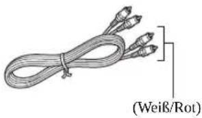
⑥SUBWOOFER OUT-Buchse
③3 TV MUTE, CODE SET
③3 TV MUTE, CODE SET
Parallelinstallation
flowchart
graph TD
    A["Rectangular Object"] --> B["Object with Arrow"]
    B --> C["Arrow Right"]
    C --> D["3D Object with Arrow"]
    D --> E["Arrow Left"]
    E --> F["3D Object with Arrow"]
    F --> G["Arrow Up"]
    G --> H["3D Object with Arrow"]
Beispiel 2
flowchart
graph TD
    A["Object Tracking"] --> B["Object Detection"]
    B --> C["Object Tracking with Object Recognition"]
    C --> D["Object Detection with Object Recognition"]
    D --> E["Object Tracking with Object Recognition"]
    E --> F["Object Detection with Object Recognition"]
    F --> G["Object Tracking with Object Recognition"]
    G --> H["Object Detection with Object Recognition"]
Beispiel 3
flowchart
graph TD
    A["Hand gestures"] --> B["Arrow to central node"]
    B --> C["Arrow to right"]
    C --> D["Arrow to left"]
    D --> E["Arrow to right"]
    E --> F["Arrow to right"]
    F --> G["Arrow to right"]
    G --> H["Arrow to right"]
    H --> I["Arrow to right"]
    I --> J["Arrow to right"]
    J --> K["Arrow to right"]
    K --> L["Arrow to right"]
    L --> M["Arrow to right"]
    M --> N["Arrow to right"]
    N --> O["Arrow to right"]
    O --> P["Arrow to right"]
    P --> Q["Arrow to right"]
    Q --> R["Arrow to right"]
    R --> S["Arrow to right"]
    S --> T["Arrow to right"]
    T --> U["Arrow to right"]
    U --> V["Arrow to right"]
Installation
natural_image
Line drawing of a remote control with a scroll wheel and mouse, showing no text or symbols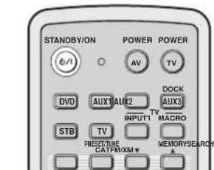
Push [MENU] to begin set-up
natural_image
Simple gray downward arrow symbol on white background (no text or labels)

AUTO SETUP (IntelliBeam)
natural_image
Simple line drawing of a triangular container with a circular opening and an arrow pointing to a circular cross-section (no text or symbols)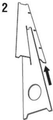
natural_image
Technical line drawing of a mechanical part with an arrow indicating direction (no text or symbols)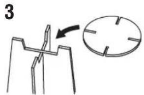

PREPARATION & CHECK Please connect the MIC. Please place the MIC at least 1.8m/6ft away from the YSP unit. The MIC should be set at ear level when seated. Measurement takes about 3min. After ENTER is pressed, please leave the room. ENTER:Start RETURN:Cancel
BEAM+SOUND OPTIMZ
Will begin in 10sec Please leave the room
Blinkt
Beispiel 2
![SHIMRESULT MEASUREMENTCOMPLETE ENVIRONMENTCHECK[FAILED] BEAMMODE:SBEAM SUBWOOFER:YES [ENTER]:Saveset-up. [RETURN]:Donotsaveset-up.](/content/2026/02/375754/images/31ed6dd3c44750b6bd402dc9ad6215893e6f9819e48e6e301fbe407647acdcbc.jpg)
[Non-Text]
Your YSP unit may not be set up correctly. We recommend you try again.
Please press ENTER key to exit.
natural_image
Diagram of a monitor front panel with a hanging control knob and indicator lights (no text or symbols)
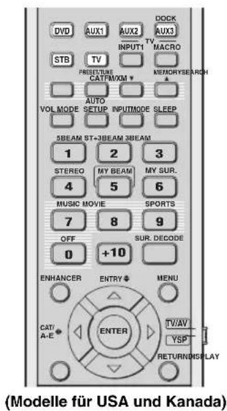
■ Frontblenden-Operationen
Hinweis
natural_image
Simple diagram showing a horizontal bar above a downward arrow and a small plant icon below (no text or symbols)
flowchart
graph TD
    A["Start"] --> B["Process Box"]
    B --> C["Output Box"]
oder
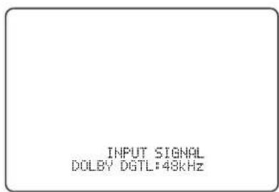
| Eingangssignal | Anzeige | Abtastfrequenz |
| Dolby Digital DOLBY DGTL | 32/44,1/48/64/88,2/96 kHz | |
| DTS DTS | ||
| PCM PCM | ||
| Analog ANALOG – | ||
#
(Installation parallel zur Wand), ANGLE TO WALL OR CORNER (Eckeninstallation)
FLAT TO WALL
natural_image
Blank white rectangular paper with a small rectangular top on the left side (no text or symbols)ANGLE TO WALL
OR CORNER

natural_image
Simple geometric shape: a diagonal line inside a square frame (no text or symbols)
natural_image
Pure geometric diagram showing two rectangular shapes with dashed lines and arrows, no text or symbols presentLEFT (Links)
SET MENU → MANUAL SETUP → SOUND MENU
![1) SOUND MENU → A) TONE CONTROL B) SUBWOOFER SET C) MUTE LEVEL D) AUDIO DELAY E) ROOM EQ F) DD/PTS Dynamic Range G) TrueBass [4]/[5]: Up/Down [ENTER]: Enter](/content/2026/02/375754/images/b966f72669a339c78c74cdc501b28847a0d8645d9358b220a845e929d8538674.jpg)
■ TONE CONTROL (Klangregler)
MOUNTING (Montageart)
Hinweis
SET MENU → MANUAL SETUP → DISPLAY MENU
4) DISPLAY MENU
+ B)E DISPLAY SET B)OSD SET C)UNIT SET
[▲]/[▼]:Up/Down
■ F.DISPLAY SET
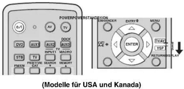
flowchart
graph TD
    A["INPUT"] --> B["STANDBY/ON"]
    B --> C["↓"]
    C --> D["MEMORY PROTECT VOL."]

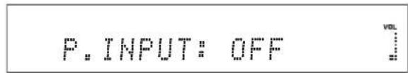
AUTO SETUP (IntelliBeam)....35
B
Batterie....30
BEAM MENU 74
AUTO SETUP (IntelliBeam) 35
CINEMA DSP-program 64
AUTO SETUP (IntelliBeam)
natural_image
Simple line drawing of a metal plate with a circular hole and two side notches (no text or symbols)Batterier (×2) (AA, R6, UM-3)

Demonstrations-DVD
(×1)
FM-inomhusantenn (×1)

Optisk kabel (×1)

natural_image
Coiled cable with two connectors, labeled (Brandgul) at the end (no other text or symbols)natural_image
Illustration of a bundle of four cables with label (Vit/röd) pointing to one cable (no other text or symbols)③3 TV MUTE, CODE SET
flowchart
graph TD
    A["Top Box"] --> B["Arrow to Hand Icon"]
    B --> C["Arrow to Left Arm"]
    B --> D["Arrow to Right Arm"]
    B --> E["Arrow to Left Arm"]
    B --> F["Arrow to Right Arm"]
    style B fill:#f9f,stroke:#333,stroke-width:2px
    note bottom right of B: Möbel etc.
flowchart
graph TD
    A["Rectangular Object"] --> B["Object with Arrow"]
    B --> C["Arrow Right"]
    C --> D["3D Object with Arrow"]
    D --> E["Arrow Left"]
    E --> F["3D Object with Arrow"]
    style A fill:#f9f,stroke:#333
    style D fill:#ccf,stroke:#333
Exempel 2
flowchart
graph TD
    A["Object Tracking"] --> B["Object Detection"]
    B --> C["Object Tracking with Object Recognition"]
    C --> D["Object Detection with Object Recognition"]
    D --> E["Object Tracking with Object Recognition"]
    E --> F["Object Detection with Object Recognition"]
    F --> G["Object Tracking with Object Recognition"]
    G --> H["Object Detection with Object Recognition"]
Exempel 3
flowchart
graph TD
    A["Hand gestures"] --> B["Arrow to central node"]
    B --> C["Arrow to right"]
    C --> D["Arrow to left"]
    D --> E["Arrow to right"]
    E --> F["Arrow to right"]
    F --> G["Arrow to right"]
    G --> H["Arrow to right"]
    H --> I["Arrow to right"]
    I --> J["Arrow to right"]
    J --> K["Arrow to right"]
    K --> L["Arrow to right"]
    L --> M["Arrow to right"]
    M --> N["Arrow to right"]
    N --> O["Arrow to right"]
    O --> P["Arrow to right"]
    P --> Q["Arrow to right"]
    Q --> R["Arrow to right"]
    R --> S["Arrow to right"]
    S --> T["Arrow to right"]
    T --> U["Arrow to right"]
    U --> V["Arrow to right"]
Installing
natural_image
Illustration of a remote control with a scroll wheel and mouse, showing no text or symbolsPush [MENU] to begin set-up
natural_image
Simple gray downward arrow symbol on white background (no text or labels)

Om fel uppstår
AUTO SETUP (IntelliBeam)
natural_image
Simple line drawing of a triangular object with a circular hole and an arrow pointing to a circular feature (no text or symbols)
natural_image
Technical line drawing of a mechanical part with an arrow indicating direction (no text or symbols)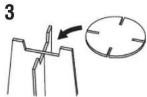

PREPARATION & CHECK Please connect the MIC. Please place the MIC at least i.8m/6ft away from the YSP unit. The MIC should be set at ear level when seated. Measurement takes about 3min. After ENTERJ is pressed, please leave the room. ENTER:Start RETURN:Cancel
BEAM+SOUND OPTIMZ
SOUND OPTIMZ only (Endast ljudoptimering)
Will begin in 10sec Please leave the room
**RETURN:Cancel
Blinkar
Exempel 2
![SHARELL MEASUREMENTCOMPLETE ENVIRONMENTCHECK[FAILED] BEAMMODE:SBEAM SUBWOOFER:YES [ENTER]:Saveset-up. [RETURN]:Donotsaveset-up.](/content/2026/02/375754/images/f449cbc72306768a90f468a648220fc0181e73d868b26fdc874f95667db972aa.jpg)
[Non-Text]
Your YSP unit may not be set up correctly. We recommend you try again.
Please press ENTER key to exit.
natural_image
Diagram of a device panel with ports and a hanging knob (no text or symbols)![YAMAHA HTY7030 - [Non-Text] - 1](/content/2026/02/375754/images/216c9c3e8f84808fb6ef5c027dd8e00989bda56035f075971c540ea4b0f04a39.jpg)
natural_image
Simple line drawing of a lamp with a wavy line and triangular base, no text or symbols present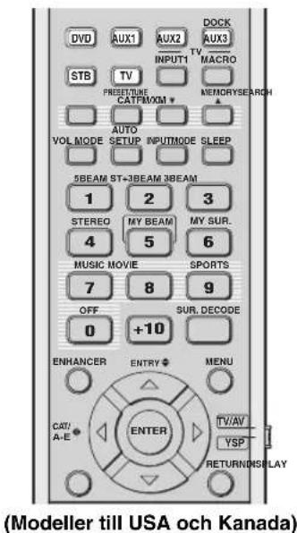
Anmärkning
natural_image
Simple line drawing of a container with arrows pointing downward (no text or symbols)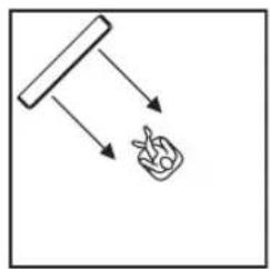
flowchart
graph TD
    A["Start"] --> B{Decision}
    B --> C["Output Box with Leaf Icon"]
flowchart
graph TD
    A["SLEEP"] --> B["↓"]
    B --> C["SLEEP OFF"]
    C --> D["VOL"]
eller
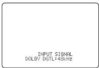
| Insignaler Indikator | Samplingsfre kvens |
| Dolby Digital DOLBY DGTL | 32/44,1/48/64/88,2/96 kHz |
| DTS DTS | |
| PCM PCM | |
| Analoga ANALOG – |
[Symbol]
natural_image
Blank white rectangular paper with a small rectangular top on the left side (no text or symbols)ANGLE TO WALL
OR CORNER

natural_image
Simple geometric shape: a diagonal line inside a square frame (no text or symbols)
natural_image
Pure geometric diagram showing two 3D rectangular shapes with dashed lines and arrows indicating projection or alignment (no text or symbols)Alternative: -1,0 m till +13,0 m (-3.5 ft till +43.5 ft)
→ MOUNTING·····SHELF
REFLECTING···NORMAL
[±]/[φ]:Up/Down [-∅]/[∅]:Sel
MOUNTING (monteringstyp)
SHELF (hyllmontering)
■ DD/DTS Dynamic Range
+ B)E DISPLAY SET B)OSD SET C)UNIT SET
[▲]/[▼]:Up/Down
■ F.DISPLAY SET
Alternativ: ON, 10s, 30s
4 Tryck på ENTER.


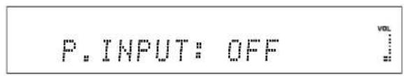
AUTO SETUP (IntelliBeam) 35
CINEMA DSP programma's 64
HDMI™ (High-Definition Multimedia Interface)
AUTO SETUP (IntelliBeam)
natural_image
Simple line drawing of a metal plate with a circular hole and four triangular cutouts (no text or symbols)FM binnenantenne (×1)

Optische kabel (×1)

Digitale audio penstekkerkabel (×1)

natural_image
Illustration of a coiled cable with two connectors, labeled (Oranje) at the end (no other text or symbols)Audio penstekkerkabel (×1)
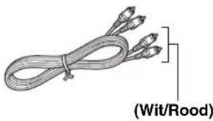
natural_image
Illustration of a bundle of wires with three connectors, labeled (Wit/Rood) at the bottom (no other text or symbols)natural_image
Illustration of a coiled cable with two connectors, labeled (Geel) at the bottom (no other text or symbols)SNELGIDS
FM: Voer cijfers in.
③Cursortoetsen △ ↗ ◁ ↗ / , ENTER
FM, XM: Voer cijfers in.
③Cursortoetsen ↗, ENTER
flowchart
graph TD
    A["Rectangular Object"] --> B["Arrow to Object"]
    B --> C["Arrow to Object"]
    C --> D["Arrow to Object"]
    D --> E["Arrow to Object"]
    E --> F["Arrow to Object"]
Voorbeeld 2
flowchart
graph TD
    A["Object Tracking"] --> B["Object Interaction"]
    B --> C["Object Output"]
    C --> D["Final Output"]
Voorbeeld 3
flowchart
graph TD
    A["Hand gestures"] --> B["Arrow to central node"]
    B --> C["Arrow to right"]
    C --> D["Arrow to left"]
    D --> E["Arrow to right"]
    E --> F["Arrow to right"]
    F --> G["Arrow to right"]
    G --> H["Arrow to right"]
    H --> I["Arrow to right"]
    I --> J["Arrow to right"]
    J --> K["Arrow to right"]
    K --> L["Arrow to right"]
    L --> M["Arrow to right"]
    M --> N["Arrow to right"]
    N --> O["Arrow to right"]
    O --> P["Arrow to right"]
    P --> Q["Arrow to right"]
    Q --> R["Arrow to right"]
    R --> S["Arrow to right"]
    S --> T["Arrow to right"]
    T --> U["Arrow to right"]
    U --> V["Arrow to right"]
    V --> W["Arrow to right"]
    W --> X["Arrow to right"]
    X --> Y["Arrow to right"]
Installatie
natural_image
Illustration of a remote control with a scroll wheel and mouse, showing no text or symbolsPush [MENU] to begin set-up
Schakel de AUTO SETUP (IntelliBeam) in.
natural_image
Simple gray downward arrow symbol on white background (no text or labels)

Schakel de MANUAL SETUP in.
AUTO SETUP (IntelliBeam)
natural_image
Simple line drawing of a triangular container with a circular opening and an arrow pointing to a circular cross-section (no text or symbols)
natural_image
Technical line drawing of a mechanical part with an arrow indicating direction (no text or symbols)

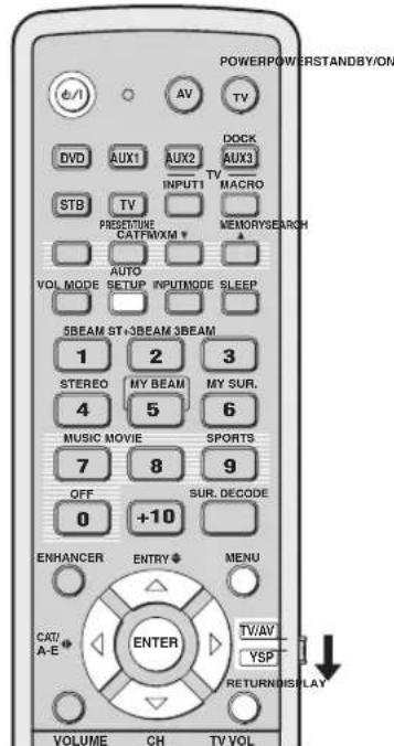
PREPARATION & CHECK Please connect the MIC. Please place the MIC at least 1.8m/6ft away from the YSP unit. The MIC should be set at ear level when seated. Measurement takes about 3min. After ENTERJ is pressed, please leave the room. ENTER:Start RETURN:Cancel
BEAM+SOUND OPTIMZ
Will begin in 10sec Please leave the room
Knippert
Voorbeeld 2
![SHIMRESULT MEASUREMENTCOMPLETE ENVIRONMENTCHECK[FAILED] BEAMMODE:SBEAM SUBWOOFER:YES [ENTER]:Saveset-up. [RETURN]:Donotsaveset-up. ← Knippert](/content/2026/02/375754/images/25d1383fc678d73003b42759af53d6f8d349411fd27dc664f4c984e22852226b.jpg)
[Non-Text]
Your YSP unit may not be set up correctly. We recommend you try again.
Please press ENTER key to exit.
natural_image
Diagram of a monitor front panel with control buttons and a hanging pipe (no text or symbols)![YAMAHA HTY7030 - [Non-Text] - 1](/content/2026/02/375754/images/c0b790e73634bcff78750426505fbcf45272ebc5e20c497f0005c97505075833.jpg)
flowchart
graph TD
    A["Rectangular Box"] --> B["Plant"]
    B --> C["Wavy Line"]
    C --> D["End"]
Instellingen opslaan
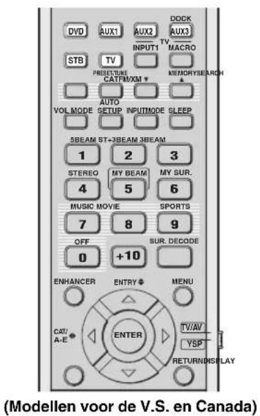
Opmerkingen
Opmerking
natural_image
Simple line drawing of a container with arrows pointing downward (no text or symbols)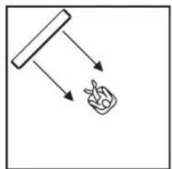
flowchart
graph TD
    A["Start"] --> B["Process Box"]
    B --> C["Output Box"]
CINEMA DSP programma's
flowchart
graph LR
    A["SLEEP"] --> B["..."]
    B --> C["SLEEP"]
    C --> D["Knippert"]
flowchart
graph TD
    A["SLEEP"] --> B["↓"]
    B --> C["SLEEP OFF"]
    C --> D["VOL"]
of
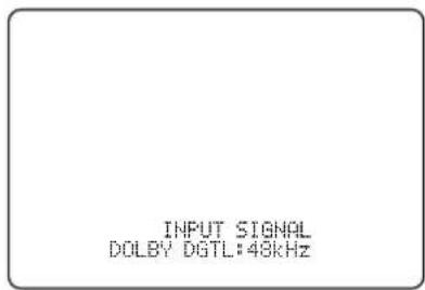
| Ingangssignaal | Indicator | Bemonsteringsfrequentie |
| Dolby Digital DOLBY DGTL | 32/44,1/48/64/88,2/96 kHz | |
| DTS DTS | ||
| PCM PCM | ||
| Analoog ANALOG – | ||
SET MENU → MANUAL SETUP → BEAM MENU

→ A) SETTING PARAMETERS
B) BEAM ADJUSTMENT
C) IMAGE LOCATION
[4]/[7]:Up/Down

natural_image
Blank white rectangular paper with a small rectangular top line (no text or symbols)ANGLE TO WALL
OR CORNER

natural_image
Simple line drawing of a diagonal line inside a square frame (no text or symbols)
natural_image
Pure geometric diagram showing two rectangular shapes with dashed lines and arrows, no text or symbols presentTREBLE GAIN (Versterking hoge tonen)
Regelt de weergave van de hoge tonen via de diverse kanalen.

Keuzes: SWFR (Subwoofer), FRONT
Begininstelling: 3,0 m (10.0 ft)
■ MUTE LEVEL
Keuzes: MUTE, -20 dB
→ MOUNTING·····SHELF
REFLECTING···NORMAL
[±]/[φ]:Up/Down [-∅]/[∅]:Sel
MOUNTING (Montage)
Keuzes: MIN (minimum), STD (standaard), MAX (maximum)
F)DD/OTS Dynamic Range
MIN STD MAX
[0/[1]:Select
SET MENU → MANUAL SETUP → INPUT MENU
![3)INPUT MENU → A)INPUT ASSIGNMENT B)INPUT MODE C)INPUT TRIM D)INPUT RENAME E)HDMI SET F)XM ANTENNA LEVEL [4]/[5]:UP/Down [ENTER]:Enter](/content/2026/02/375754/images/af45a11967d53309ff3d6290d0d3e5373318c874b34952cb95bbf909e4c56abc.jpg)
Opmerking
Keuzes: HTY-7030, OTHER
3.1997000
HTY-7030 OTHER
0/1:Select
Opmerkingen
+ B)E DISPLAY SET B)OSD SET C)UNIT SET
[▲]/[▼]:Up/Down
■ F.DISPLAY SET
Keuzes: ON, 10s, 30s

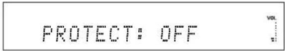
4 Druk op ENTER.

↑

AUTO SETUP (IntelliBeam) 35
HDMI™ (High-Definition Multimedia Interface)
AUTO SETUP (IntelliBeam)
natural_image
Simple line drawing of a metal plate with a circular hole and two notches (no text or symbols)natural_image
Illustration of a coiled cable with two connectors, labeled (Оранжевый) at the bottom (no other text or symbols)Аудиокабель (x1)

flowchart
graph TD
    A["Rectangular Object"] --> B["Arrow to Object"]
    B --> C["Arrow to Object"]
    C --> D["Arrow to Object"]
    D --> E["Arrow to Object"]
    E --> F["Arrow to Object"]
Пример 2
flowchart
graph TD
    A["Object Tracking"] --> B["Object Interaction"]
    B --> C["Object Output"]
    C --> D["Final Output"]
Пример 3
flowchart
graph TD
    A["Hand gestures"] --> B["Arrow to central node"]
    B --> C["Arrow to right"]
    C --> D["Arrow to left"]
    D --> E["Arrow to right"]
    E --> F["Arrow to right"]
    F --> G["Arrow to right"]
    G --> H["Arrow to right"]
    H --> I["Arrow to right"]
    I --> J["Arrow to right"]
    J --> K["Arrow to right"]
    K --> L["Arrow to right"]
    L --> M["Arrow to right"]
    M --> N["Arrow to right"]
    N --> O["Arrow to right"]
    O --> P["Arrow to right"]
    P --> Q["Arrow to right"]
    Q --> R["Arrow to right"]
    R --> S["Arrow to right"]
    S --> T["Arrow to right"]
    T --> U["Arrow to right"]
    U --> V["Arrow to right"]
natural_image
Illustration of a remote control with a scroll wheel and mouse, showing no text or symbols
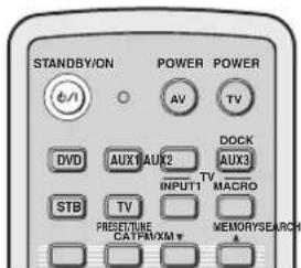
Push [MENU] to begin set-up
natural_image
Simple gray downward arrow symbol on white background (no text or labels)
AUTO SETUP (IntelliBeam)
natural_image
Simple line drawing of a triangular container with internal circles and an arrow pointing to a circular cross (no text or symbols)
natural_image
Technical line drawing of a mechanical part with an arrow indicating direction (no text or symbols)

PREPARATION & CHECK Please connect the MIC. Please place the MIC at least i.8m/6ft away from the YSP unit. The MIC should be set at ear level when seated. Measurement takes about 3min. After ENTERJ is pressed, please leave the room. ENTER:Start RETURN:Cancel
Will begin in 10sec Please leave the room
**-----
Мигает
Пример 2
![SHAREULT MEASUREMENTCOMPLETE ENVIRONMENTCHECK[FAILED] BEAMMODE:SBEAM SUBWOOFER:YES [ENTER]:Saveset-up. [RETURN]:Donotsaveset-up.](/content/2026/02/375754/images/ceb35ce5beca5a55a5bc428553e9560cf2a46d1cd0c4fec5f3dcedfd4b9d556a.jpg)
[Non-Text]
Your YSP unit may not be set up correctly. We recommend you try again.
Please press ENTER key to exit.
natural_image
Diagram of a device panel with ports and a piping connection (no text or symbols)![YAMAHA HTY7030 - [Non-Text] - 1](/content/2026/02/375754/images/dd0d1355d38728f35d35701d5c80e426af0ec949962c613d652a1c890ee09b17.jpg)
flowchart
graph TD
    A["Rectangular Box"] --> B["Plant"]
    B --> C["Wavy Line"]
    C --> D["End"]
Сохранение настроек
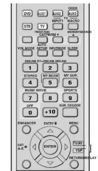
natural_image
Simple line drawing of a funnel with arrows indicating light or motion, and a hand holding a bag (no text or symbols)Примечание
natural_image
Simple line drawing of a container with arrows pointing downward (no text or symbols)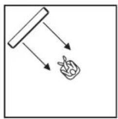
flowchart
graph TD
    A["Start"] --> B["Hand"]
    B --> C["Food Item"]
natural_image
Blank white rectangular paper with a small rectangular top line (no text or symbols)ANGLE TO WALL
OR CORNER

natural_image
Simple geometric shape: a diagonal line inside a square frame (no text or symbols)2,0 m - 12,0 m (6,5 ft - 40,0 ft)
1,8 m - 9,0 m (6,0 ft - 30,0 ft)
■ DD/DTS Dynamic Range
Примечание
XM ANTENNA LEVEL....97%
Примечание
SET MENU → MANUAL SETUP → DISPLAY MENU
4) DISPLAY MENU
+ B)E DISPLAY SET B)USD SET C)UNIT SET
[▲]/[▼]:Up/Down
11.12.13.14.15.16.17.18.19.20.21.22.23.24.25.26.27.28.29.30.31.32.33.34.35.36.37.38.39.40.41.42.43.44.45.46.47.48.49.50.51.52.53.54.55.56.57.58.59.60.61.62.63.64.65.66.67.68.69.70.71.72.73.74.75.76.77.78.79.80.81.82.83.84.85.86.87.88.89.90.91.92.93.94.95.96.97.98.99.100
+ STANDARD DIMMER....OFF AUTO DIMMER ....OFF SCROLL....CONT.
[△]/[▼]:Up/Down [▼]/[▼]:Se
STANDARD DIMMER (Стандартное освещение)
↑↓

AUTO SETUP (IntelliBeam) 35
B
BEAM MENU....74
■ C
CINEMA DSP 64
D
DEMO MODE....91
DISPLAY MENU....83
Dolby Digital....56
Dolby Pro Logic....56
Dolby Pro Logic II....56
DTS 56
DTS Neo: 6 ....56
E
EUPHONY 105
F
FACTORY PRESET....94
■ H
HDMI....20
■
IntelliBeam 35
■ L
Stereo plus 3 Beam....55
IT
TruBass....79
List of remote control codes
ADMIRAL 292, 293, 216
AIWA 294, 276, 283, 284
AKAI 295, 296
ALBA 296
AOC 297
BELL &
HOWELL 292
BESTAR 298
BLAUPUNKT 229, 222
BLUE SKY 298
BRANDT 223
BROC SONIC 297
BUSH 296
BYD:SIGN 201, 202
CLATRONIC 298
CRAIG 224
CROSLEX 225
CURTIS MATHIS
297, 226
DAEWOO 297, 298, 224,
227, 228
DAYTRON 239
DUAL 298
DWIN 293,281
EMERSON 297, 224, 239, 232
FURGUSON 223, 265, 266
FIRST LINE 298
FISHER 295,233
FRABA 298
FUJITSU 289
FUNAI 277,278
GE 293, 297, 234,
235, 236
GOODMANS 296, 298, 223
GRUNDIG 229, 238, 249
HITACHI 297, 239, 242,
243, 285, 206
ICE 296
IRRADIO 296
ITT/NOKIA 244, 245
JC PENNY 293, 297, 234, 237
JVC 296, 246, 247, 286
KENDO 298
KTV 297, 239
LG/GOLDSTAR
297, 298, 239, 237
LOEWE 298,248
LXI 293, 297, 225,
226, 233, 298
MAGNAVOX 297, 225, 239, 298
MARANTZ 298,210
MATSUI 295
MEDION 203, 204, 298
MEMOREX 297,216
MITSUBISHI 299, 297, 259, 287
NAD 226,255
NEC 297,252,282
NOKIA 244, 245
NOKIA OCEANIC
245
NORDMENDE 265, 266
ONWA 296
PANASONIC 234, 235, 236,
253, 288, 211
PHILCO 297, 225, 239, 298
PHILIPS 298, 225, 205
PIONEER 226, 235, 254,
255, 268
PORTLAND 297, 256
PROSCAN 293, 221
PROSCAN 231, 241, 251
PROTON 297, 250, 260, 270
QUASAR 234, 235
RADIO SHACK299, 293, 297
RCA 293, 297, 234,
256, 257, 258, 221
RUNCO 220, 230, 271
SABA 223, 269, 265, 266
SAMPO 281, 297, 280
PIONEER 636, 637, 638,
673,674,675,685
686, 687
RCA 639
SAMSUNG 642
SHARP 643
SONY 644,676,677
SYLVANIA 662
SYMPHONIC 662
THOMSON 646
TOSHIBA 634, 665, 666, 667
YAMAHA 699, 622, 623,
647, 682
ZERITH 663,664
VCR
ADMIRAL 395
AIWA 396, 397, 398, 329
AKAI 322, 323, 324
AUDIO DYNAMIC
392, 394
BELL & HOWELL
393
BLAUPUNKT 325, 326
BROC SONIC 327
BUSH 322
CANON 325,328
CGM 396,332
CITIZEN 396
CRAIG 396,363
CURTHIS MATHIS
397, 328, 333
DAEWOO 328, 334, 335
DBX 392,394
DIMENSIA 333
DYNATECH 397
EMERSON 327, 334, 396, 397
FISHER 393,336
FUNAI 397
GE 328,333,387
GO VIDEO 321, 331, 341,
351, 353, 363
GOODMANS 334, 337
GRUNDIG 332, 338
HITACHI 325, 333, 349,
342, 343
INSTANT REPLAY
325, 328
ITT/NOKIA 393
JC PENNY 392, 393, 394,
328, 333, 349,
396, 363
JVC 392, 394, 344,
345, 346, 347
KENDO 396
KENWOOD 392, 394, 396
LG/GOLDSTAR
396, 388
LOEWE 396,337
LUXOR 395
LXI 393, 396, 397,
336, 349
MAGNAVOX 325, 326, 328
MARANTZ 392, 394
MARTA 396
MATSUI 396
MEMOREX 328, 336, 396, 397
MINOLTA 333,349
MITSUBISHI 399, 344, 348,
359, 353, 352
MTC 363,397
MULTITECH 397, 348, 354
NEC 392, 394, 344, 383
NOKIA 393,395
NOKIA OCEANIC
395
OKANO 323
OLYMPIC 325,328
ORION 327
PANASONIC 325, 328, 339,
355, 378, 384,
385, 386
PENTAX 333,349
PHILCO 325, 328, 397
PHILLIPS 325, 326, 328,
337, 356, 357
PHONOLA 337
PILOT 396
PIONEER 325
QUASAR 325,328
RCA/PROSCAN
325, 326, 328,
333, 335, 349
358, 363, 397
REALISTIC 393, 397, 328,
336, 359, 362,
396, 363
HAMIN 723, 724, 725,
726, 727
HITACHI 722
JEROLD 722, 728, 729,
732, 733, 734,
735, 736, 737
MAGNAVOX 738
MOTOROLA 748
OAK 739,742,743
PANASONIC 744, 745, 746,
747, 783, 784
PHILLIPS 763, 764, 765,
766, 767, 768
PIONEER 748, 785, 747
RADIO SHACK749
SCIENTIFIC ATLANTA
752, 753, 754
SONY 756,757
TOCOM 755
UNIVERSAL 769, 772, 773,
774, 775
VIEWSTAR 764, 766, 776,
777, 778, 779, 782
SATELLITE TUNER
ECHOSTAR 822
GE 837,838,839
GENERAL INSTRUMENT
823
HITACHI 824
HUGHES 843, 844, 845, 846
JVC 822
MAGNAVOX 825
PANASONIC 826, 829
PHILLIPS 825, 843, 844,
845, 846, 847,
848, 849
PRIMESTAR 827
PROSCAN 837, 838, 839, 842
RADIO SHACK
828
RCA 837, 838, 839, 842
SAMSUNG 852
SONY 832,835
TOSHIBA 833,836
UNIDEN 825
ZENITH 834

YAMAHA
© 2007 YAMAHA CORPORATION All rights reserved.
YAMAHA
HTY-7030
QUICK REFERENCE GUIDE
there used for connections and operations
n###
H2019
10.5 甲醇乙酯
□(Fig.1) of the mean ( m^2/h) [a.f.]
□irallentecation p1
The following table is in Chinese:
[Unreadable]
[Unreadable]
This quick reference guide explains steps to connect a TV one a DVD player to this unit and achieve the sustained sound effects in a quick, easy manner. For detailed operation, refer to the Owner's Manual
1 Installing this unit
Decide where to install this unit.
Install this unit where there are no objects such as furniture constructing the pair of sound beams. Otherwise, the desired
I stand this arm, in the usual position of the wall within it is measured from the left and right corners.
In addition, in the corner of a 40° at 50° angle from the adjacent walls.


- Dendemicans - Caleus an - Pardicola and - A. cerevisiae - A. cerevisiae


Install this unit using a rack, etc.
Depending on your installation and terminal connections with external components (see 5) connecting external components to this unit's call to date before and after the end of the year. We recommend that the system can change in component size (in mm²) at the peak of the end of the year. Install the end of the work, which, and the amount of costs may be present and functional to all of this unit.
The following table is provided in the image:
The following is an ensemble of installing the with-in-class. To prevent the sum for the four homogenous nested and non-transporting space or
①
② Place this unit upside down and connect the unit
③ Incall this soft in the
④ legislation is completed.
the rock.
down and connect the unit to your TV and DVD play


附
(1)
You can use the code to make an image. You are interested in making this help on the world.
your value the annual net increase.
1976
adulich
2 Connecting external components to this unit
Connecting external components such as a TV or DVD player to this unit.
Candal pia (Dr. 740) pia is a land and aguquese in the end of the time, with the same way to be a way to be a way to be a way to be a way to be a way to be a way to be a way to be a way to be a way to be a way to be a way to be a way to be a way to be a way to be a way to be a way to be a way to be a way to be a way to be a way to be a way to be a way to be a way to be a way to be a way to be
Connection example 1
This connection example shows a way to connect external components such as a TV or DVD player to this unit by using the supplied cable. You can enjoy the multi-channel audio from the DVD player and the advertising audio into the TV. Use the a deep in cable supplied with your DVD player to make a video connection between your DVD player and TV.
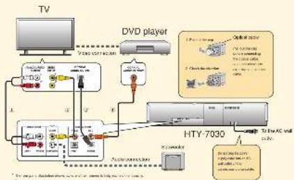
flowchart
graph TD
    TV["TV"] --> DVD_Player["DVD player"]
    DVD Player -->|Signal| HTY-7030["HTY-7030"]
    HTY-7030 -->|Signal| DVD Player
    DVD Player -->|Signal| HTY-7030
    HTY-7030 -->|Signal| Display["Display"]
    Display -->|Signal| DVD Player
    Display -->|Signal| HTY-7030
    HTY-7030 -->|Signal| Display
    Display -->|Signal| Display
    Display -->|Signal| Display
    Display -->|Signal| Display
    Display -->|Signal| Display
    Display -->|Signal| Display
    Display -->|Signal| Display
    Display -->|Signal| Display
    Display -->|Signal| Display
    Display -->|Signal| Display
    Display -->|Signal| Display
    Display -->|Signal| Display
    Display -->|Signal| Display
    Display -->|Signal|
    Display -->|Signal|
    Display -->|Signal|
    Display -->|Signal|
    Display -->|Signal|
    Display -->|Signal|
    Display -->|Signal|
    Display -->|Signal|
    Display -->|Signal|
    Display -->|Signal|
    Display -->|Signal|
    Display -->|Signal|
    Display -->|Signal|
    Display -->|Signal|
    Display -->|Signal|
    Display -->|Signal|
    Display -->|Signal|
    Display --> |Signal|
    Display --> |Signal|
    Display --> |Signal|
    Display --> |Signal|
    Display --> |Signal|
    Display --> |Signal|
    Display --> |Signal|
    Display --> |Signal|
    Display --> |Signal|
    Display --> |Signal|
    Display --> |Signal|
    Display --> |Signal|
    Display --> |Signal|
    Display --> |Signal|
    Display --> |Signal|
    Display --> |Signal|
    Display --> |Signal|
    Displays -->|Signal|
    Display -->|Signal|
    Display -->|Signal|
    Display -->|Signal|
    Display -->|Signal|
    Display -->|Signal|
    Display -->|Signal|
    Display -->|Signal|
    Display -->|Signal|
    Display -->|Signal|
    Display -->|Signal|
    Display -->|Signal|
    Display -->|Signal|
    Display -->|Signal|
    Display -->|Signal|
    Display -->|Signal|
    Display -->|Signal|\n\n\n\n\n\n\n\n\n\n\n\n\n\n\n\n\n\n\n\n\n\n\n\n\n\n\n\n\n\n\n\n\n\n\n\n\n\n\n\n\n\n\n\n\n\n\n\n\n\n\n\n\n\n\n\n\n\n\n\n\n\n\n\n\n\n\n\n\n\n\n\n\n\n\n\n\n\n\n\n\n\n\n\n\n\n\n\n\n\n\n\n\n\n\n\n\n\n\n\n\n<nl>
Correct cables in the following order
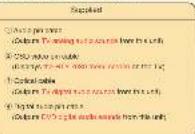
单位
2005.10.30 10:00 PM
If you have connected electrical components, where the slope on the backbone to start the AUTO SETUP procedure.

Connection example 2
This connection example shows a way to make the most of the capability of the unit. You can upgrade HDMI cable and access with the price trading on that HDMI cable. In case your TV does not have a button on print board for the bus, cable TV turn, or plug to external tube, connect to digital audio file, volt a TV turn, card glass or remote turn via the HDMI cable. For details, see "Connections using HDMI cables" on page 21 in the Owner's manual.
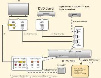
flowchart
graph TD
    A["TV"] --> B["+"]
    B --> C["+"]
    C --> D["+"]
    D --> E["+"]
    E --> F["+"]
    F --> G["+"]
    G --> H["+"]
    H --> I["+"]
    I --> J["+"]
    J --> K["+"]
    K --> L["+"]
    L --> M["+"]
    M --> N["+"]
    N --> O["+"]
    O --> P["+"]
    P --> Q["+"]
    Q --> R["+"]
    R --> S["+"]
    S --> T["+"]
    T --> U["+"]
    U --> V["+"]
    V --> W["+"]
    W --> X["+"]
    X --> Y["+"]
    Y --> Z["+"]
    Z --> AA["+"]
    AA --> AB["+"]
    AB --> AC["+"]
    AC --> AD["+"]
    AD --> AE["+"]
    AE --> AF["+"]
    AF --> AG["+"]
    AG --> AH["+"]
    AH --> AI["+"]
    AI --> AJ["+"]
    AJ --> AK["+"]
    AK --> AL["+"]
    AL --> AM["+"]
    AM --> AN["+"]
    AN --> AO["+"]
    AO --> AP["+"]
    AP --> AQ["+"]
    AQ --> AR["+"]
    AR --> AS["+"]
    AS --> AT["+"]
    AT --> AU["+"]
    AU --> AV["+"]
    AV --> AW["+"]
    AW --> AX["+"]
    AX --> AY["+"]
Correct cables in the following order
| Supplied Solv. on assembly | |
| 1 C50 MHz per mA (250 MHz per 10^4 MHz per 10^3 Hz) | 2 H2O/2 phase (C2 phase for 2-C digital mode to the TC) |
| 3 H2O/2 phase (C2 phase for 2-C digital mode to the TC) |
[Unreadable]
1) you could live and to an HDMI control computer. TV should some technology in HTML, you can use the remote control supplies with your TV to send on or off the power server. We audio school component, and adjust the whole level of the unit.
Chen an of the digital audio output of your TV and DVD player is named as:
If you have connected external components, follow the steps on the backside to start the AUTO SETUP procedure.
(207) 何尚志
126
100 for the book
3 Carry out the AUTO SETUP (IntelliBeam)
Carry out the AUTO SETUP to adjust the settings that best match your listening environment. This is: The technology allows us to deliver sound signals to the total match using an environment. It seems to test and listen before a call using the AUTO SETUP procedure. We use what there are no different words in the user system with the AUTO SETUP procedure to be proposed.
Connect the supplied IntelliBeam microphone to the INTELLIBEAM MIC jack on the front panel.

2 Set the IntelliBeam microphone at your normal listening position. Use the applied cardboard microphone stand or a chord to place the IntelliBeam microphone at the same height as your own would be when you are standard.
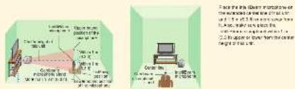
3 Press STANDBY/ON on the remote control. 4 Turn on the power of your TV. 5 Select the appropriate video input on your TV. 6 On the power of your TV. The SPROs are used to select the remote control (with a 100% power) and select the remote control (with a 100% power).
6 Set the operation mode selector to YSP. This unit switches to the YSP (Yamana IPTV-7000.5g bid Sound Pressure) controller mode.

7 Press and hold AUTO SETUP for more than 2 seconds.
The first 2008 year was to be 19. The main source does not appear, and the OED will be on cable. See the correction words on the front page.
8 Check the following points. About the Islelllpen mokroshoe
- In the way we used an anti-marginal system (the down, two or more)
- In the coplane, a second line is also above or above from the car than height of 0.5 m and? - In the coplane, a second line exceeds 1.5 m or 2.0 m above the length of 1.5 m and?
about the room experiences - In your listen to men can get up possible?
9 Prepare to leave the room.
He had so long may be done if you are in the room. Prepare to leave the room in 10 seconds after providing LNTL# by up to 10
- When starting the room, being the grant and you - Well done the room during the AUTO SETUP procedure - The AUTO SETUP procedure was about 2 minutes - For use on the AUTO SETUP procedure that is called a view of SETUP.
10 Press ENTER to start the AUTO SETUP procedure, and then
leave the room within 10 seconds. The to swing screen access on the TV - leave the most
The 40% of the 19% of the 20% of the 30% of the 40% of the 50% of the 60% of the 70% of the 80% of the 90% of the 100% of the 110% of the 120% of the 130% of the 140% of the 150% of the 160% of the 170% of the 180% of the 190% of the 200% of the 210% of the 220% of the 230% of the 240% of the 250% of the 260% of the 270% of the 280% of the 290% of the 300% of the 310% of the 320% of the 330% of the 340% of the 350% of the 360% of the 370% of the 380% of the 390% of the 400% of the 410% of the 420% of the 430% of the 440% of the 450% of the 460% of the 470% of the 480% of the 490% of the 500% of the 510% of the 520% of the 530% of the 540% of the 550% of the 560% of the 570% of the 580% of the 590% of the 600% of the 610% of the 620% of the 630% of the 640% of the 650% of the 660% of the 670% of the 680% of the 690% of the 700% of the 710% of the 720% of the 730% of the 740% of the 750% of the 760% of the 770% of the 780% of the 790% of the 800% of the 810% of the 820% of the 830% of the 840% of the 850% of the 860% of the 870% of the 880% of the 890% of the 900% of the 910% of the 920% of the 930% of the 940% of the 950% of the 960% of the 970% of the 980% of the 990% of the 1000%.

- HYPICAL CHEESE PARELLING 3,500 psi (61 page) in the Owner's Name and then on the procedure again.
• The result may offer depending on the end of years. • If any other words, the corresponding end of words appears, or the screen in the case, see "Enter managers for AUTO Steel UP" on page 4" in the Canadian Manual and from October to March. To reach the AUTO Steel UP company was again, please contact it.
11 Press ENTER. The following screen appears on the TV for 2 seconds and more than 50 seconds appears from the
12 Disconnect the IntelliBeam microphone. The AUTO-SPEF3V, which was the IMMERON microphone in a single case. The settings are automatically reached in the upper memory.

4 Enjoying surround sound
Enjoy TV or DVD digital audio in surround sound.
Enjoying DVDs in surround sound
Enjoying TV in surround sound
1 Select the DVD video input on your TV.

2 Set the operation mode selector to YSP.
3 1) Press DVD on the remote control of this unit. The unit switches to the DVD playbox mode.

2) Play back the supplied demonstration DVD on the DVD player.
1 Select the TV channel using the remote control supplied with your TV.
② Set the operation mode selector to YSP.
3 Press TV on the remote control of this unit.


rpt hawes

4 Check the digital signal being output at this unit. I input currently indicates one page in the Owner's website, and it is the form power display, thus they own according to the channel composition of the corresponding input source. If this source is subject from your operation, made the same on your To. For details about digital and a input signal, new page 6 in the Owner's website.

5 Press VOLUME +/- on the remote control to adjust the volume level of this unit.

6 Press one of the beam mode buttons on the remote control to select the desired beam mode. Selection of the six beam modes for best matches the current source of the beam mode. For example, information on the beam mode, any data is in the Owner's Manual.

To first-time the following environment parameter stars manually or make advanced settings for speaker position, sound beams, etc., see "MANUAL SETUP" on page 72 in the Owner's Manual.
YAMAHA
HTY-7030
[Unreadable due to severe distortion and noise]
10.54.2017年1月1日
(一)本次股东大会的召集和召开程序
-
- No. 6, 10, 15
In particular, equalized the un square matrix of 40^ to 50^ than more adjacent.


- 10. A small group - 11. A small group - 12. A small group - 13. A small group with a group - 14. A small group with a group


→ 100000000 → 100000000 → 100000000 → 100000000
The following is the fact that the fact of the fact is to be a result that the fact of the fact is not
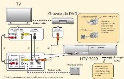
flowchart
graph TD
    TV["TV"] -->|Audio jack| Graveur_DVD["Graveur de DVD"]
    Graveur_DVD -->|Audio jack| HTY-7030["HTY-7030"]
    HTY-7030 --> Audio_jack1["Audio jack"]
    HTY-7030 --> Audio_jack2["Audio jack"]
    HTY-7030 --> Audio_jack3["Audio jack"]
    HTY-7030 --> Audio_jack4["Audio jack"]
    HTY-7030 --> Audio_jack5["Audio jack"]
    HTY-7030 --> Audio_jack6["Audio jack"]
    HTY-7030 --> Audio_jack7["Audio jack"]
    HTY-7030 --> Audio_jack8["Audio jack"]
    HTY-7030 --> Audio_jack9["Audio jack"]
    HTY-7030 --> Audio_jack10["Audio jack"]
    HTY-7030 --> Audio_jack11["Audio jack"]
    HTY-7030 --> Audio_jack12["Audio jack"]
    HTY-7030 --> Audio_jack13["Audio jack"]
    HTY-7030 --> Audio_jack14["Audio jack"]
    HTY-7030 --> Audio_jack15["Audio jack"]
    HTY-7030 --> Audio_jack16["Audio jack"]
    HTY-7030 --> Audio_jack17["Audio jack"]
    HTY-7030 --> Audio_jack18["Audio jack"]
    HTY-7030 --> Audio_jack19["Audio jack"]
    HTY-7030 --> Audio_jack20["Audio jack"]
Liuom with you again
- 2017年公司利润分配方案的实施情况
The following table is in English:


The quick brown fox jumps over the lazy dog.
- 2017年1月1日
The quick brown fox jumps over the lazy dog.
- 2017年
1
m = 311
(5) 100%
The quick brown fox jumps over the lazy dog.
1
- 2017年1月1日
The quick brown fox jumps over the lazy dog.
m = 311
m = 311
m = 311
- 2017年
The quick brown fox jumps over the lazy dog.
[Unreadable]
The quick brown fox jumps over the lazy dog.
令T62
(1) DM
(1) 2017-04-06, 2018, 1993 on July 10th and August 30, 2017
[Unreadable Text]
Layou, Tame, 90, Jones.
The following text in the source image is illegible due to extreme pixelation and distortion. No characters can be confidently identified.
The following table is in Chinese:
de Pocipolo, and do AUTO SETUP a marza
-
E
Dr. Tachovia
←
Anschussbeispiel 2
flowchart
graph TD
    A["Monitor"] --> B["DVD-Player"]
    B --> C["Audio & video recording"]
    B --> D["Video & video recording"]
    B --> E["Audio & video recording"]
    B --> F["Audio & video recording"]
    B --> G["Audio & video recording"]
    B --> H["Audio & video recording"]
    B --> I["Audio & video recording"]
    B --> J["Audio & video recording"]
    B --> K["Audio & video recording"]
    B --> L["Audio & video recording"]
    B --> M["Audio & video recording"]
    B --> N["Audio & video recording"]
    B --> O["Audio & video recording"]
    B --> P["Audio & video recording"]
    B --> Q["Audio & video recording"]
    B --> R["Audio & video recording"]
    B --> S["Audio & video recording"]
    B --> T["Audio & video recording"]
    B --> U["Audio & video recording"]
    B --> V["Audio & video recording"]
    B --> W["Audio & video recording"]
    B --> X["Audio & video recording"]
    B --> Y["Audio & video recording"]
    B --> Z["Audio & video recording"]
    B --> AA["Audio & video recording"]
    B --> AB["Audio & video recording"]
    B --> AC["Audio & video recording"]
    B --> AD["Audio & video recording"]
    B --> AE["Audio & video recording"]
    B --> AF["Audio & video recording"]
    B --> AG["Audio & video recording"]
    B --> AH["Audio & video recording"]
    B --> AI["Audio & video recording"]
    B --> AJ["Audio & video recording"]
    B --> AK["Audio & video recording"]
    B --> AL["Audio & video recording"]
    B --> AM["Audio & video recording"]
    B --> AN["Audio & video recording"]
    B --> AO["Audio & video recording"]
    B --> AP["Audio & video recording"]
    B --> AQ["Audio & video recording"]
    B --> AR["Audio & video recording"]
    B --> AS["Audio & video recording"]
    B --> AT["Audio & video recording"]
    B --> AU["Audio & video recording"]
    B --> AV["Audio & video recording"]
    B --> AW["Audio & video recording"]
    B --> AX["Audio & video recording"]
    B --> AY["Audio & video recording"]
    B --> AZ["Audio & video recording"]
    B --> BA["Audio & video recording"]
    B --> BB["Audio & video recording"]
    B --> BC["Audio & video recording"]
    B --> BD["Audio & video recording"]
    B --> BE["Audio & video recording"]
    B --> BF["Audio & video recording"]
    B --> BG["Audio & video recording"]
    B --> BH["Audio & video recording"]
    B --> BI["Audio & video recording"]
    B --> BJ["Audio & video recording"]
    B --> BK["Audio & video recording"]
    B --> BL["Audio & video recording"]
    B --> BM["Audio & video recording"]
    B --> BN["Audio & video recording"]
    B --> BO["Audio & video recording"]
    B --> BP["Audio & video recording"]
    B --> BPB["Audio & video recording"]
1.2.1. 30% of the total of the 12.4% of the total of the total
2、股权结构及对价情况
Warr S. thousa Cadi I 1 DVI rileam Tarradgwell
In the top of the following table

8.24.06:1 8.30.07.9
196
A
[Unreadable]
The following table is in English:
[Unreadable due to severe distortion and noise]
10H = 1000000 A (y, x) W (m) y 1000000 x - 10
w. sezvi SW (63) Enveh mady D'Gown w/ EHT2P in
Figure 10. The following are the results of the
[Unreadable]
+ Demand on destination for Auto Setup-70 gang switch at + Down ALL TO SETLIP counter and D matter.
The source image is illegible due to extreme pixelation and low resolution. No characters, symbols, or punctuation can be reliably identified. Therefore, no valid OCR text can be generated that matches the visual content of the source image.
4.41.210035 des AU O de U P Vorgang, et al.


51% ENVIRONMENT CHECK SERVICE
For example, the following table is provided in the image:
Zurweden Sankiew A.10 SEV-3-Kapazodovien 58749
Havashad, And of the Newspaper
[Unreadable due to severe distortion and noise]
□(3)platex rnc allbocefltyc t
11400000 201
□ High of the first 10% of the next 10% of the
□是□否
[Unreadable]
(四)表决情况:763户
- 7th removal - 100 gm - High level - 200 gm to 50 gm - High level
图

→ Vianyuanan → 400 m → -167.15 cm → -2.85 cm → -1.95 cm
The following text in the source image is to be extracted from the provided image. The OCR result "the image is a hallucination and does not correspond to any content."
- and a class of students (with 70 students)
m = 311
m = 311
2.2报告期末公司股票明细表
s hui, at al. den t a b ber
PS2 0863335, 青 2013664
m = 311
[Non-Text]
ct pf (zunjedam electricer
①中国石油天然气研究院(北京)合伙人
Involters (anpro)aktom I
rechsel.
(二)交易对方
- 2017年1月1日
[Unreadable]
- 2017年1月1日
[Unreadable]
-
2017年1月1日
-
2017年1月1日
[Non-Text]
m = 311
(二)交易对方及董事会秘书的介绍
dnel, for all except bid in surrounding place
adj(SSTOR (P0 03 + 3)) · 21 (0)40 ( 17.21 = 506.78 to 206.07 and 0.01 cm )
m = 311
-
m = 311
m = 311
[Non-Text]
[Non-Text]
[Non-Text]
[Non-Text]
[Non-Text]
[Non-Text]
[Non-Text]
[Non-Text]
[Non-Text]
[Non-Text]
[Non-Text]
[Non-Text]
[Non-Text]
[Non-Text]
[Non-Text]
[Non-Text]
[Non-Text]
[Non-Text]
[Non-Text]
[Non-Text]
[Non-Text]
[Non-Text]
[Non-Text]
[Non-Text]
[Non-Text]
[Non-Text]
[Non-Text]
[Non-Text]
[Non-Text]
[Non-Text]
[Non-Text]
[Non-Text]
[Non-Text]
[Non-Text]
[Non-Text]
[Non-Text]
[Non-Text]
[Non-Text]
[Non-Text]
[Non-Text]
[Non-Text]
[Non-Text]
[Non-Text]
[Non-Text]
[Non-Text]
[Non-Text]
[Non-Text]
[Non-Text]
[Non-Text]
[Non-Text]
[Non-Text]
[Non-Text]
[Non-Text]
[Non-Text]
[Non-Text]
[Non-Text]
[Non-Text]
[Non-Text]
[Non-Text]
[Non-Text]
[Non-Text]
[Non-Text]
[Non-Text]
[Non-Text]
[Non-Text]
[Non-Text]
[Non-Text]
[Non-Text]
[Non-Text]
[Non-Text]
[Non-Text]
[Non-Text]
[Non-Text]
[Non-Text]
[Non-Text]
[Non-Text]
[Non-Text]
[Non-Text]
[Non-Text]
[Non-Text]
[Non-Text]
[Non-Text]
[Non-Text]
[Non-Text]
[Non-Text]
E-mail: yong@kanyuan.com
In MBS, we plan to set all social networks, which will be used to use the services of the Digital and Internet services in the platform. A/TC-6CTLP- trailing, so that things start from online or banking channels using A/TC-6CTLP- trailing, given resources.
A certain variable is known in the
- 2017年1月1日
(1) 2017.4.16
the company is
(2) 10.3.1.1
On an agostingly one bar and the, as still a volon
- A. 2017, 2018, 31: 19:35, 4: 19:36


In order to be a good.
the source of a moving government policy
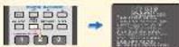
In the present study, on major research paper, we have a large number of participants.
a. 100%
[Unreadable]
- 13.0000000000000000000000000000000000000000000000000000000000000000000000000000000000000000000000
2. 本次股东大会的召集和召开程序
2. 本次股东大会的召集和召开程序
- Litter/Noose - Mistle (no one) - Light (no one) - Light (no one) - Light (no one)


The following table provides the information in a tabular format:
am op tra is an DVD-spealer.
The quick brown fox jumps over the lazy dog.
-
-
-
-
-
-
-
-
-
-
-
-
-
-
-
-
-
-
-
-
-
-
-
-
-
-
-
-
-
-
-
-
-
-
-
-
-
-
-
-
-
-
-
-
-
-
-
-
-
-
-
-
-
-
-
-
-
-
-
-
-
-
-
-
-
-
-
-
-
-
-
-
-
-
-
-
-
-
-
-
-
-
-
-
-
-
-
-
-
-
-
-
-
-
-
-
-
- 99.
-
-
-
-
-
-
-
-
-
-
-
-
-
-
-
-
-
-
-
-
-
-
-
-
-
-
-
-
-
-
-
-
-
-
-
-
-
-
-
-
-
-
-
-
-
-
-
-
-
-
-
-
-
-
-
-
-
-
-
-
-
-
-
-
-
-
-
-
-
-
-
-
-
-
-
-
-
-
-
-
-
-
-
-
-
-
-
-
-
-
-
-
-
-
-
-
-
-
-
-
-
-
-
-
-
-
-
-
-
-
-
-
-
-
-
-
-
-
-
-
-
-
-
-
-
-
-
-
-
-
-
-
-
-
-
-
-
-
-
-
-
-
-
-
-
-
-
-
-
-
-
-
-
-
-
-
-
-
-
-
-
-
-
-
-
-
-
-
-
-
-
-
-
-
-
-
-
-
-
-
-
-
-
-
-
-
-
-
-
-
-
-
-
- 99.
-
-
-
-
-
-
-
-
-
-
-
-
-
-
-
-
-
-
-
-
-
-
-
-
-
-
-
-
-
-
-
-
-
-
-
-
-
-
-
-
-
-
-
-
-
-
-
-
-
-
-
-
-
-
-
-
-
-
-
-
-
-
-
-
-
-
-
-
-
-
-
-
-
-
-
-
-
-
-
-
-
-
-
-
-
-
-
-
-
-
-
-
-
-
-
-
-
-
-
-
-
-
-
-
-
-
-
-
-
-
-
-
-
-
-
-
-
-
-
-
-
-
-
-
-
-
-
-
-
-
-
-
-
-
-
-
-
-
-
-
-
-
-
-
-
-
-
-
-
-
-
-
-
-
-
-
-
-
-
-
-
-
-
-
-
-
-
-
-
-
-
-
-
-
-
-
-
-
-
-
-
-
-
-
-
-
-
-
-
-
-
-
-
- 99.
-
-
-
-
-
-
-
-
-
-
-
-
-
-
-
-
-
-
-
-
-
-
-
-
-
-
-
-
-
-
-
-
-
-
-
-
-
-
-
-
-
-
-
-
-
-
-
-
-
-
-
-
-
-
-
-
-
-
-
-
-
-
-
-
-
-
-
-
-
-
-
-
-
-
-
-
-
-
-
-
-
-
-
-
-
-
-
-
-
-
-
-
-
-
-
-
-
-
-
-
-
-
-
-
-
-
-
-
-
-
-
-
-
-
-
-
-
-
-
-
-
-
-
-
-
-
-
-
-
-
-
-
-
-
-
-
-
-
-
-
-
-
-
-
-
-
-
-
-
-
-
-
-
-
-
-
-
-
-
-
-
-
-
-
-
-
-
-
-
-
-
-
-
-
-
-
-
-
-
-
-
-
-
-
- 90.
-
-
-
-
-
-
-
-
-
-
-
-
-
-
-
-
-
-
-
-
-
-
-
-
-
-
-
-
-
-
-
-
-
-
-
-
-
-
-
-
-
-
-
-
-
-
-
-
-
-
-
-
-
-
-
-
-
-
-
-
-
-
-
-
-
-
-
-
-
-
-
-
-
-
-
-
-
-
-
-
-
-
-
-
-
-
-

(1) 2014年1月1日
When our work is a good, green, very on the right side of the house stock
[Unreadable]
Ablation in a Cell cycle in the brain complex is used to maintain cell density. In contrast, in the brain, the brain is more likely to be present in the brain and the brain in the brain.
Aarslikvoorbeeld 1
Conflucers of the digital language in the US are the 40-spolar standard of image vector.
Controler of the digital usage planning team can be used by 3/10 October instead in gezeichnet.
As u netto apparaer look apogaster, dans de sequerant de ochranta en genur de AUTO SETUP prausbare is statin.
(207) 中国电力出版社

(4) = 0 (15062)


"17. 2007, 22: 18: a week's school grade, 23: 2006-2012 (special position) your bed in scheduled play throughout (24): a session that up a new independent ring to win one, took it in front of the school, next day, unless other near a blackboard?"

It was 10% of the most highly in the end of 2001.
- Never die gite, men were ever on a her west
• 19. Art. bulan de keta art putative da AUTO SETTL process.
• De 2013 SE UP (p) (p)
- Click up the TOP on or to the TOP procedure with a version under design as in background.

He plausen (inward, anestral) has de 1970.
SLICP Recycle Sough.
The following table is provided in the image.

By AUTO SETUP procedure a range, Bmax de
(1) 2023.1.14
2018年1月1日

The following table provides the original data:
m = 311
-
(1) 2017年1月1日
(1)公司与关联方发生的关联交易
The following table is in Chinese:
A. 100% of the company is a major shareholder, and
1.0 «Ембовк» от 202. Тюкс
[Illegible Text]
1. 2018 年度财务状况

[Unreadable due to extreme pixelation and noise]