
HTP678 - Loudspeaker ONKYO - Free user manual and instructions
Find the device manual for free HTP678 ONKYO in PDF.
| Product Type | 5.1.2-channel Home Cinema Speaker Pack |
| Brand | ONKYO |
| Model | HTP678 |
| Front Speakers (SKF-693) | 2-way bass-reflex type, Impedance 6 Ω, Sensitivity 84.5 dB/W/m |
| Center Speaker (SKC-591N) | 2-way bass-reflex type, Impedance 6 Ω, Sensitivity 86 dB/W/m |
| Surround Speakers (SKR-590) | Full-range sealed type, Impedance 6 Ω, Sensitivity 81 dB/W/m |
| Height Speakers (integrated in front) | Full-range sealed type, Impedance 6 Ω, Sensitivity 81 dB/W/m |
| Subwoofer (SKW-658) | Bass-reflex type, Power 80 W RMS, Response 27–150 Hz |
| Front Speaker Dimensions | 155 × 467 × 183 mm |
| Front Speaker Weight | 3.6 kg |
| Center Speaker Dimensions | 420 × 115 × 119 mm |
| Center Speaker Weight | 2.3 kg |
| Surround Speaker Dimensions | 115 × 230 × 96 mm |
| Surround Speaker Weight | 1.0 kg |
| Subwoofer Dimensions | 230 × 425 × 410 mm |
| Subwoofer Weight | 7.7 kg |
| Subwoofer Power Supply | 220–240 V AC, 50/60 Hz, Power Consumption 20 W |
| Key Features | Dolby Atmos surround sound, auto standby, wall-mountable |
| Maintenance | Clean with a soft dry cloth. Do not use solvents. |
| Safety | Respect cable polarity, do not short-circuit, wall mount on studs or anchors. |
Frequently Asked Questions - HTP678 ONKYO
User questions about HTP678 ONKYO
0 question about this device. Answer the ones you know or ask your own.
Ask a new question about this device
Download the instructions for your Loudspeaker in PDF format for free! Find your manual HTP678 - ONKYO and take your electronic device back in hand. On this page are published all the documents necessary for the use of your device. HTP678 by ONKYO.
USER MANUAL HTP678 ONKYO
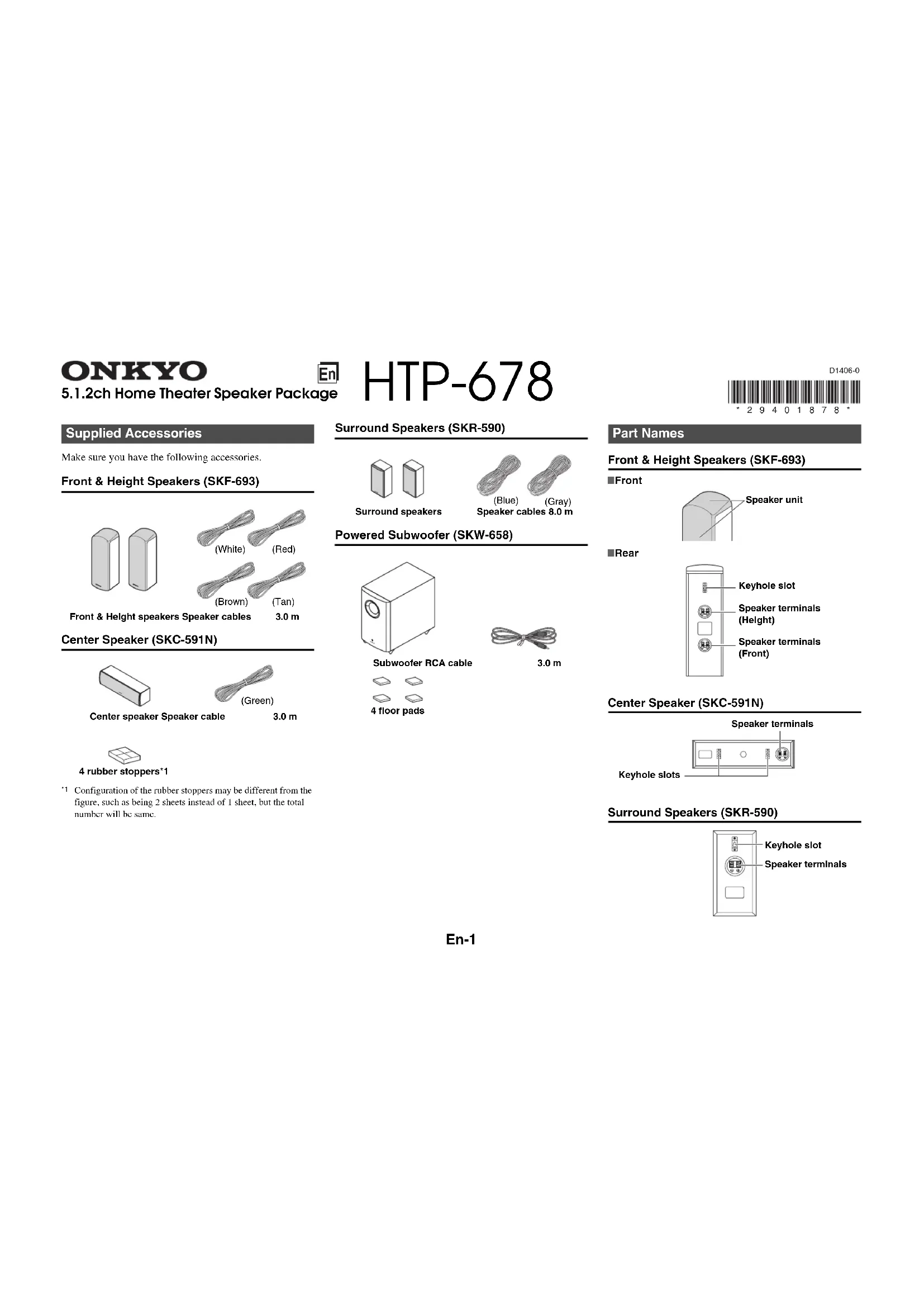
Supplied Accessories
Make sure you have the following accessories.
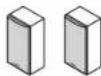
Front & Height Speakers (SKF-693)
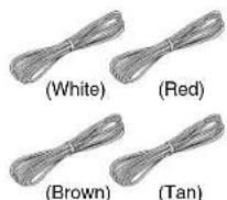
Front & Height speakers Speaker cables 3.0 m
Center Speaker (SKC-591N)
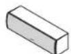
Center speaker Speaker cable

3.0 m

4 rubber stoppers*1
1 Configuration of the rubber stoppers may be different from the figure, such as being 2 sheets instead of 1 sheet, but the total number will be same.
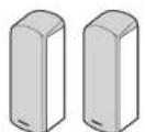
Surround Speakers (SKR-590)
Surround speakers
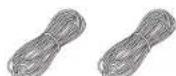
(Blue) (Gray) Speaker cables 8.0 m
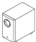
Powered Subwoofer (SKW-658)
Subwoofer RCA cable
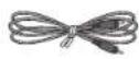
3.0m

4 floor pads

Part Names
Front & Height Speakers (SKF-693)
■Front
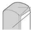
Speaker unit
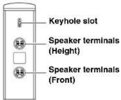
Rear
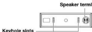
Center Speaker (SKC-591N)
Surround Speakers (SKR-590)
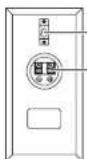
Keyhole slot
Speaker terminals
Caution
The front grilles are not designed to be removed so do not attempt to remove them forcibly, as this will damage them.
Powered Subwoofer (SKW-658)
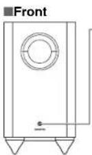
Status indicator
Off: Subwoofer in standby mode or disconnected from power source Blue:Subwoofer on
The status indicator lights blue when low frequency sound is being passed through the speaker.
The indicator does not light in the normal dialog or high frequency sound.
Note
- The indicator does not indicate that power supply of the subwoofer has turned on.
With the Auto Standby function, the SKW-658 automatically turns on when an input signal is detected in standby mode. When there's no input signal for a while, the SKW-658 automatically enters standby mode.
Rear
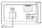
To AC outlet
OUTPUT LEVEL control
This control is used to adjust the volume of the subwoofer.
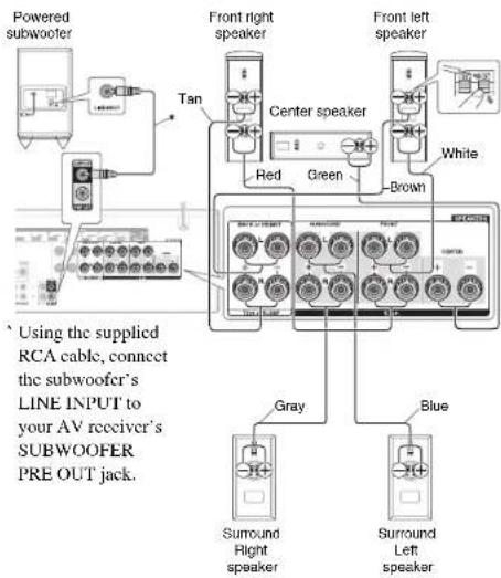
LINE INPUT
This RCA input should be connected to the subwoofer pre out on your AV receiver with supplied RCA cable.
Note
The Auto Standby function turns the subwoofer on when the input signal exceeds a certain level. If the Auto Standby function does not work reliably, try slightly increasing or decreasing the subwoofer output level on your receiver.
Before Using the Home Theater Speaker Package
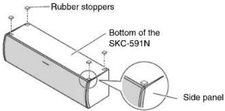
Using the Rubber Stoppers for a More Stable Platform
We recommend using the supplied rubber stoppers to achieve the best possible sound from your speakers. The rubber stoppers prevent the speakers from moving, providing a more stable platform. Use rubber stoppers for the center speaker.
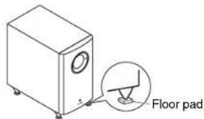
Using the Floor Pads for Subwoofer
If the subwoofer is placed on a hard floor (wood, vinyl, tile, etc.) and playback is very loud, the subwoofer's feet may damage the flooring. To prevent this, place the supplied pads underneath the subwoofer's feet. The pads also provide a stable base for the subwoofer.
En-2
Setting the Subwoofer Level
To set the level of the subwoofer, use the OUTPUT LEVEL control. Set it so that bass sounds are evenly balanced with the treble sounds from the other speakers. Because our ears are less sensitive to very low bass sounds, there's a temptation to set the level of the subwoofer too high. As a rule of thumb, set the subwoofer level to what you think is the optimal level, and then back it off slightly.
Wall Mounting
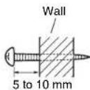
To mount the front/surround speakers vertically, use the keyhole slot shown to hang each speaker on a screw that's securely screwed into the wall.

To mount the center speaker horizontally, use the two keyhole slots shown to hang the speaker on two screws that are securely screwed into the wall.
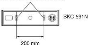
Keyhole slots for wall mounting
Tip
- If the center speaker is tilted, loosen the screw on the declined side to move upward so that the speaker could be adjusted vertically.
Caution
- A mounting screw's ability to support a speaker depends on how well it's anchored to the wall. If you have hollow walls, screw each mounting screw into a stud. If there are no studs, or the walls are solid, use suitable wall anchors. Use screws with a head
diameter of 9mm or less and a shank diameter of 4mm or less. With hollow walls, use a cable/pipe detector to check for any power cables or water pipes before making any holes.
- Leave a gap of between 5mm and 10mm between the wall and the base of the screw head, as shown (We recommend that you consult a home installation professional).
Enjoying Home Theater
The Home Theater means that you can enjoy surround sound with a real sense of movement in your own home just like being in a movie theater or concert hall.
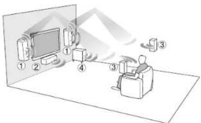
① Front speakers (SKF-693)
They should be positioned facing the listener at about car level, and equally spaced from the TV. Angle them inward slightly so as to create a triangle, with the listener at the apex.
Height speakers
This speaker is type of integrated with the front speakers and height speakers. The height speakers designed with the top of the front speakers are facing toward the ceiling to create an elevated audio effect in the Dolby Atmos and Dolby Surround listening modes by providing sounds echoing off the ceiling.
② Center speaker (SKC-591N)
Position it close to your TV (preferably on top) facing forward at about ear level, or at the same height as the front left and right speakers.
③ Surround speakers (SKR-590)
Position them at the sides of the listener, or slightly behind, about 60 to 100cm above ear level. Ideally they should be equally spaced from the listener.
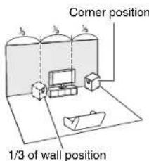
④ Subwoofer (SKW-658)
The subwoofer handles the bass sounds of the LFE (Low-Frequency Effects) channel and bass from the satellite speakers when a crossover is specified. The volume and quality of the bass output from your subwoofer will depend on its position, the shape of your listening room, and your listening position. In general, a good bass sound can be obtained by installing the subwoofer in a front corner, or at one-third the way along the front wall, as shown.
Connecting the Speakers
Speaker Connection Precautions
Read the following before connecting your speakers:
- Turn off your receiver before making any connections.
- Pay close attention to speaker wiring polarity. Connect positive (+) terminals to only positive (+) terminals, and negative (-) terminals to only negative (-) terminals. If the speakers are wired incorrectly, the sound will phase and will sound unnatural.
- Be careful not to short the positive and negative wires. Doing so may damage your amp.

Specifications
■Powered Subwoofer (SKW-658)
Type Bass-Reflex
Input sensitivity/Impedance
re
Rated output Power (TEC)
80 watts minimum continuous power, 4 ohms, driven at 100Hz with a
maximum total harmonic distortion of 1%
Frequency response 27 Hz to 150 Hz
Cabinet capacity 24.
Dimensions (W× H× D) 230 mm × 425 mm × 410 mm (incl. projection)
Weight 7.7kg
Audio input 1 (RCA analog mono)
Drivers unit 20 cm Conc × 1
Power supply AC 220-240 V, 50/60 Hz
Power consumption 20 W
Other Auto Standby function
Non-magnetic shielding
■Front & Height Speakers (SKF-693)
Front
Type 2 Way Bass-Reflex
Impedance 6Ω
Maximum input power
Sensitivity
84.5 dB/W/m
Frequency response 55 Hz to 50 kHz
Crossover frequency 4kHz
Cabinet capacity 5.7 L
Dimensions (W× H× D) 155 mm × 467 mm × 183 mm
(incl. grille and projection)
Weight 3.6kg
Drivers unit 12 cm OMF Cone Woofer x 1
2.5 cm Balanced Dome × 1
Terminal
Spring type color coded
Keyhole slot
Available
Grille
Fixed
Other Non-magnetic shielding
Height
Type Full Range Closed Box
Impedance 6 Ω
Maximum input power 130 W
Sensitivity
81 dB/W/m
Frequency response 80 Hz to 20 kHz
Cabinet capacity 1.0 L
Dimensions (W× H× D) 155 mm x 467 mm x 183 mm
(incl. grille and projection)
Weight 3.6kg
Drivers unit 8 cm Cone Speaker
Terminal
Spring type color coded
Keyhole slot
Available
Grille
Other Non-magnetic shielding
Center Speaker (SKC-591N)
Type 2 Way Bass-Reflex
Impedance 6Ω
Maximum input power 130 W
Sensitivity 86 dB/W/m
Frequency response 65 Hz to 50 kHz
Crossover frequency 6kHz
Cabinet capacity 2.8 L
Dimensions (W× H× D) 420mm× 115mm× 119mm (incl. grille and projection)
Weight 2.3kg
Drivers unit 8 cm Conc Woofcr × 2
2.5 cm Balanced Dome × 1
Terminal Spring type color coded
Keyhole slot Available
Grille Fixed
Other Non-magnetic shielding
Surround Speakers (SKR-590)
Type Full Range Closed Box
Impedance 6Ω
Maximum input power 130W
Sensitivity
81 dB/W/m
Frequency response 80Hz to 20kHz
Cabinet capacity 1.0 L
Dimensions (W× II× D) 115 mm × 230 mm × 96 mm
(incl. grille and projection)
Weight 1.0kg
Drivers unit 8 cm Cone Speaker × 1
Terminal Spring type color coded
Keyhole slot Available
Grille Fixed
Other Non-magnetic shielding
Specifications and appearance are subject to change without prior notice.
Note
For non-magnetic shielded speakers:
Try moving the speakers away from your TV or monitor. If discoloration should occur, turn off your TV or monitor, wait 15 to 30 minutes, and then turn it back on again. This normally activates the degaussing function, which neutralizes the magnetic field, thereby removing any discoloration effects.
ONKYO

4 protections on acautchouc*1
Ubergangsfrequency 4kHz
Gehause
Schlüssellochschitz Vorhanden
Gitter Fixed
Schlüssellochschlitz
Vorhanden
Glitter
Fixed
(C) Copyright 2014 Onkyo Corporation Japan. All rights reserved.
- SUPPLIED ACCESSORIES
- FRONT & HEIGHT SPEAKERS (SKF-693)
- CENTER SPEAKER (SKC-591N)
- SURROUND SPEAKERS (SKR-590)
- POWERED SUBWOOFER (SKW-658)
- PART NAMES
- CAUTION
- STATUS INDICATOR
- NOTE
- REAR
- OUTPUT LEVEL CONTROL
- LINE INPUT
- BEFORE USING THE HOME THEATER SPEAKER PACKAGE
- USING THE RUBBER STOPPERS FOR A MORE STABLE PLATFORM
- USING THE FLOOR PADS FOR SUBWOOFER
- SETTING THE SUBWOOFER LEVEL
- WALL MOUNTING
- TIP
- ENJOYING HOME THEATER
- HEIGHT SPEAKERS
- CONNECTING THE SPEAKERS
- SPEAKER CONNECTION PRECAUTIONS
- SPECIFICATIONS
- FOR NON-MAGNETIC SHIELDED SPEAKERS
- ONKYO
Brand : ONKYO
Model : HTP678
Category : Loudspeaker