GR3 - Air Conditioning Aermec - Free user manual and instructions
Find the device manual for free GR3 Aermec in PDF.

| Product type | Electronic controller for chilled water units and heat pumps |
| Brand | Aermec |
| Model | GR3 |
| Category | Air conditioning (regulation) |
| Main functions | Temperature regulation (cold/heat), alarm management, time scheduling (with PGS accessory), probe display |
| Display | 3 digits + 4 LED indicators |
| Controls | Control panel with keys: probe reading, alarms, SET menu, modification, navigation, local/remote mode, heating/cooling, on/off, alarm reset |
| Power supply | Via the unit's electronic board (not specified separately) |
| Compatible accessories | Remote panel PR3, time scheduler PGS |
| Temperature ranges | Cold: -10°C to +20°C; Heat: +30°C to +50°C |
| Operating modes | Local (L) and remote (R) |
| Alarm management | Alarm display and history (up to 25 entries minimum) |
| Protections | Antifreeze, high/low pressure switches, thermal-magnetic breakers, flow switches |
| Maintenance | No specific user maintenance; refer to the manual for configurations |
| Safety | Automatic alarms; manual reset possible; do not reset repeatedly |
| Spare parts / Repairability | Accessories: PR3 and PGS; integrated electronic board; modifications reserved for technical service |
| Available languages | Italian, English, German, French (configurable) |
| General information | ISO 9001 compliant; original manual in French available |
Frequently Asked Questions - GR3 Aermec
User questions about GR3 Aermec
0 question about this device. Answer the ones you know or ask your own.
Ask a new question about this device
Download the instructions for your Air Conditioning in PDF format for free! Find your manual GR3 - Aermec and take your electronic device back in hand. On this page are published all the documents necessary for the use of your device. GR3 by Aermec.
USER MANUAL GR3 Aermec
Electronic regulation for chillers and air and water cooled heat pumps
MANUEL D'UTILISATION
- Characteristics of the regulation 3
- User interface.. 3
- Control panel description 4
- Reading menu.. 5
- Turning on/off (local mode) 7
- Season change
- Working temperature ...setting..8
- Setting menu 13
- Control settings for remote panel 15
- Alarms 16
CHARACTERISTICS OF THE REGULATION1.
The command panel of the unit allows the quick setting of the machine's operating parameters, their visualisation at any time, and the immediate summary of the machine's operating status. The display is made up of 3 figures and 4 LEDs to signal, the type of working, the visualisa
tion of the parameters set or measured, and any alarms that have been activated. The card memorises all the settings saved with each modification and used for re-ignition after a switch-off owing to lack of voltage. With the installation of the remote control panel PR3, it is
possible to control, from a distance, the turning on and off, the setting of working mode [cold-hot], and the visualisation of the alarms summary with a red indicator light [alarms].
USER INTERFACE2.
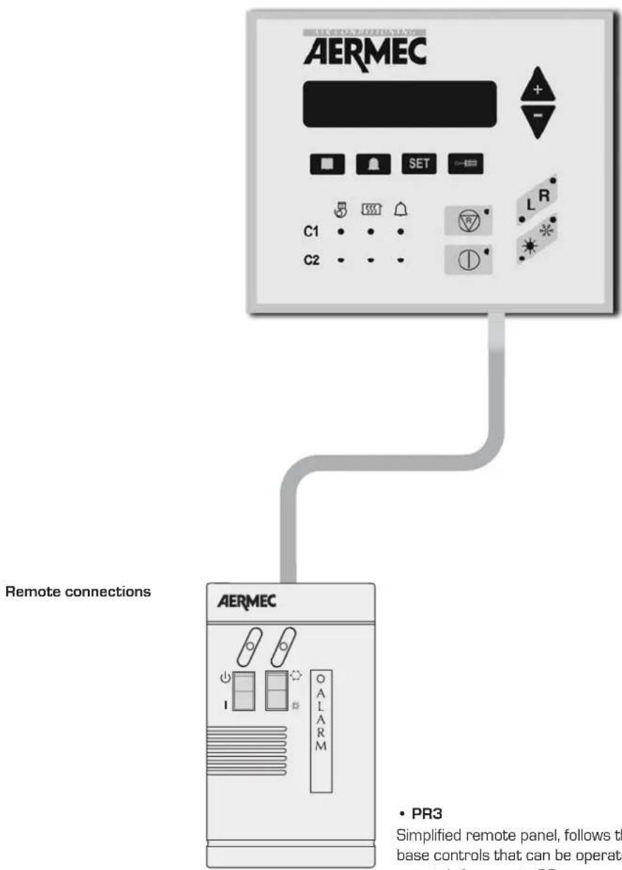
- PR3
Simplified remote panel, follows the base controls that can be operated remotely from up to 30m.
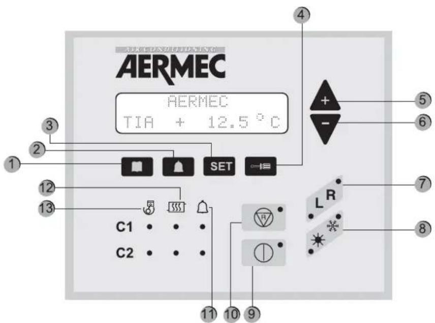
CONTROL PANEL DESCRIPTION3.
| Key Meaning | |
| 1 Visualisation of machine probe readings | |
| 2 | Visualisation of triggered alarm list |
| 3 Visualisation of operational parameters menu | |
| 4 Key to change operational parameters | |
| 5 and 6 Navigation keys | |
| 7 | Sets the unit control, which can be local [L], from the panel on board the machine, or remote (R), from remote panel or supervisor. The active setting is indicated by the switching on of the corresponding indicator light. |
| 8 Sets heating * or cooling * mode; | |
| 9 | Turns the machine on or off by setting it to STAND-BY, [only the electronic card and the electric heater are powered]; |
| 10 Cancels machine alarms and restarts it (for further information, see alarm table) | |
| 11 Led indicator of current alarms | |
| 12 Led indicator of current defrosting mode | |
| 13 Led indicator of operating compressor | |
FIRST TIME THE MACHINE IS SWITCHED ON
The first time the machine is switched on, it carries out a self-configuration operation and a series of checks through which operating parameters and electrical connections of the machine are checked. After the autotest, the company logo and
the machine type are displayed for some seconds. Then, the panel is prepared for displaying the machine probe readings (key activated).
| Reading acronym Meaning NRA NRC NRL NBW NLW | ||||||
| TIA | Read temperature at the evaporator inlet | √√ | √ | √ | √ | |
| TIAH | Temperature read at the condenser inlet | |||||
| TAE | Outside air temperature | √ | √ | √ | ||
| TUA C1 | Temperature read at evaporator outlet for circuit 1 (or the single-evaporator model) | √√ | √√ | |||
| DELTA C1 | Temperature between evaporator inlet and outlet for circuit 1 (or the single-evaporator model) | √√ | √√ | |||
| TUAH C1 | Temperature read at the condensator outlet for circuit 1 or single-condenser. | |||||
| DELTA C1 | Temperature between condenser inlet and outlet for circuit 1 (or the single-evaporator model) | |||||
| P.B.C1 | Low-pressure reading in circuit 1 | √√ | √√ | |||
| P.A.C1 | High-pressure reading in circuit 1 | √√ | √√ | |||
| TL C1 | Liquid temperature in circuit 1 | |||||
| P.IN S1 | Calculation of defrosting initial pressure for circuit 1 | |||||
| ATTESA C1 | Minimum waiting time to restart compressor 1 | √√ | √√ | |||
| ATTE.C1A | Minimum waiting time to restart compressor 1A | √√ | √√ | |||
| ATTE.C1B | Minimum waiting time to restart compressor 1B | CPx6 | CPx6 | CPx6 | ||
| P.B.C2 | Low pressure reading in circuit 2 | √√ | √√ | |||
| TUAH C2 | Temperature read at the condenser outlet for circuit 2 | Cx2 | Cx2 | |||
| P.A.C2 | High-pressure reading in circuit 2 | √√ | √√ | |||
| TL C2 | Liquid temperature in circuit 2 | |||||
| Reading acronym Meaning NRA NRC NRL NBW NLW | |||||
| P.IN S2 | Calculation of defrosting initial pressure for circuit 2 | ||||
| ATTESA C2 | Minimum waiting time to restart compressor 2 | ||||
| ATTE. C2A | Minimum waiting time to restart compressor 2A | ||||
| ATTE. C2B | Minimum waiting time to restart compressor 2B | CPx6 | CPx6CPx6 | ||
| SBRINA C1 | Minimum waiting time before defrosting circuit 1 | ||||
| SBRINA C2 | Minimum waiting time before defrosting circuit 2 | ||||
| TEV1 | Gas temperature read at evaporator inlet of circuit 1 | ||||
| TEV2 | Gas temperature read at evaporator inlet of circuit 2 | ||||
| TAC | Temperature read in storage | ||||
| TIR | Reading of inlet temperature for heat recovery | ver T ver T | ver T | ver T ver T | |
| TUR1 | Temperature read at the outlet for heat recovery of circuit 1 | ver T ver T | ver T | ver T ver T | |
| TUR2 | Temperature read at the outlet for heat recovery of circuit 2 | ver T ver T | ver T | ver T ver T | |
| TFC | Temperature read at the freecooling battery inlet | Free | Free | Free | |
| KEY | |
| √ | Reading available both in cooling only and heat pump models |
| Coo | Reading available only in G-compressor models |
| Reading present in all versions, but available only in heat pump models | |
| Coo | Reading available only in bi-condenser models |
| Reading available in models with Total Recovery | |
| Free | Reading available only in FREE COOLING models |
Image Procedure to be adopted

TURNING ON:
For unit commissioning, press only ON key. When the led is on, the unit is ready for operation.
TURNING OFF:
Turn it off immediately with the same button.
Only if the PR3 accessory is installed, the unit shall be completely off after seven seconds.
SEASON CHANGE6.
Image Procedure to be adopted
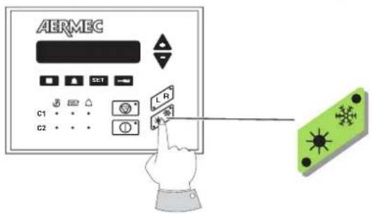
To activate the season change, just press the key indicated next. So that the operation is correctly finished, the machine shall be activated both in remote or in local.
Two symbols are present in the "season change" key:
- The symbol ※ identifies the heat pump operation;
- the symbol * identifies cooling operation.
DISPLAY OF THE FUNCTIONING PARAMETERS
For displaying operation parameters, the key SET is pressed; the indicator light key SET is on and the parameters indicated in chapter "SETTING MENU" are displayed. Parameters can be sequentially displayed by using the arrow keys e The writing "Set Setting" appears on the first line and the set value on the second line.
To change the set parameter, press the key and the key
led will also be on. The setting displayed can be modified by using the arrow keys.
The wording on the first line changes to "Modified Setting". By pressing the key again, the modification is saved and, by using the arrow keys, it is possible to scan set parameters again to find a new parameter to be changed.
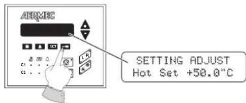
COOLING SET POINT SETTING
Image Procedure to be adopted
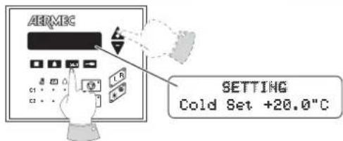
To access the parameter menu, first press the SET key and browse through by means of the arrow keys up to "Cooling Set".
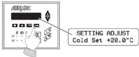
Then, to set the COOLING SET value, just press the screwdriver key and enter into the modification of the set involved.
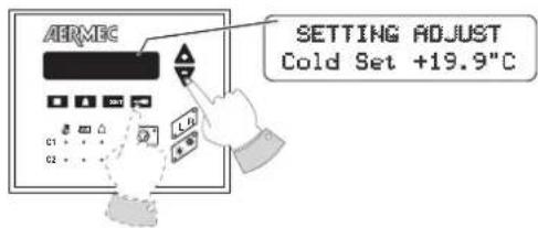
At this stage, by increasing or decreasing its value, the parameter can be changed by means of the arrows [+ and -] . Once the desired temperature is decided, just confirm the operation by pressing again the screwdriver key.
HEATING SET POINT SETTING
Image Procedure to be adopted
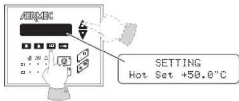
To access the parameter menu, first press the SET key and browse through by means of the arrow keys up to "Heating Set".
Then, to set the COOLING SET value, just press the screwdriver key and enter into the modification of the set involved.
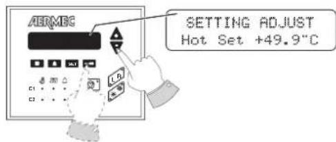
At this stage, by increasing or decreasing its value, the parameter can be changed by means of the arrows [+ and -] . Once the desired temperature is decided, just confirm the operation by pressing again the screwdriver key.
Cooling set point values
Minimum -10°C
Maximum 20^
Heating set point values
Minimum 30^
Maximum 50^ C
N.B.
There is a second cooling operation set point (parameter: 2nd C. set), and a second heating working set point (parameter: 2nd H. set). Both parameters [2nd C. set - 2nd H. set] can be operated when the digital input [M11 3-4] is closed. For further information, consult the installer or the Technical After Sales Service.
| SETTING OF TIME AND DAY OF THE WEEK (available with PGS accessory only) | |
| Image Procedure to be adopted | |
| AERMEG SETTING 00:00 Monday | To access the parameter menu, first press the SET key and browse through by means of the arrow keys up to TIME and DAY visualisation. |
| AERMEG INSERT CODE 00 00 00 | To set the TIME and DAY, just press the screwdriver key. At this stage the writing "ENTER CODE" will be displayed. The code is that by default [00 00 00]. |
| AERMEG SETTING ADJUST 00:00 Monday | Just press the screwdriver key to confirm. Thus, the modification of the set involved is accessed. |
| AERMEG SETTING ADJUST 15:30 Monday | By means of the arrow keys, first the time is modified (first led on). Once the time is decided, press the key SET to confirm and the third led will be automatically on. Then, modify the day of the week with the arrow keys. |
| AERMEG SETTING ADJUST 10 00 008 | Press the screwdriver key and the display visualisation will shift to DAY, MONTH and YEAR setting. With the arrow keys and the first led on, the day can be modified; with the second led on, the month is modified and with the third, the year. |
| AERMEG SETTING 15:30 Monday | Once time, day, month and year are set, just press the screwdriver key again to save the set values. The display will return to the initial screen. |
| TIMER OPERATION MODE (available with PGS accessory only) | |
| Image Procedure to be adopted | |
| AERMEC SETTING Timer NAME | To access the parameter menu, first press the SET key and browse through by means of the arrow keys up to the parameter "Timer". |
| AERMEC INSERT CODE 00 00 000 | Press the screwdriver key. At this stage, the writing "ENTER CODE" will be displayed. The code is the one by default (OO 00 00). Just press the screwdriver key for a second time to confirm. |
| AERMEC SETTING Timer NONE | By acting on the arrows, move to the programming mode desired. There are three alternatives: (NONE - DAY -WEEK). |
| SET IMPOSTATO Timer NOHERE | NONE mode: The programming timer is disabled. |
| SET IMPOSTATO Timer DAY | DAY mode: It is possible to set, along the day, two operation time bands. - The Daily setting is visualised - Monday to Sunday settings are not visualised. |
| SET IMPOSTATO Timer WEEK | WEEK mode: It is possible, for each day of the week, two operation time bands. - Monday to Sunday settings are visualised. - The Daily setting is not visualised |
Once the desired option is selected, confirm by pressing the screwdriver key.
N.B. ON/OFF TIMER: To program the timer, it is necessary to have access either to the remote or the local panel.
| TIME BAND SETTING | |
| Day mode | |
| Image Procedure to be adopted | |
| AHRMEC SETTING Day | Press the SET key, act on the arrow keys until the "Daily" setting is visualised. |
| AHRMEC INSERT CODE 00 00 0000 | Press the screwdriver key. At this stage, the writing "ENTER CODE" will be displayed. The code is that by default (00 00 00). |
| AHRMEC START 1 00:00K STOP 1 00:00K | Just press the screwdriver key a second time to confirm. At this stage, the menu to modify time bands is entered. |
| AHRMEC START 1 00:20K STOP 1 00:50K | Then, act on arrow keys to change START 1 values [at the same time, STOP 1 values will be also in progress]. Confirm with the screwdriver key to modify only the STOP 1. |
| AHRMEC START 1 00:20 STOP 1 00:50K | With the arrow keys, modify STOP 1 values and provide final confirmation by pressing the screwdriver key. |
| AHRMEC START 2 06:00K STOP 2 06:00K | The second time band is now visualised. Act on arrow keys to change START 2 values (at the same time, STOP 2 values will be also in progress). Confirm with the screwdriver key to modify only the STOP 2. |
| AHRMEC START 2 06:00 STOP 2 06:30K | With the arrow keys, modify STOP 2 values and provide final confirmation by pressing the screwdriver key. |
| Week mode | |
| Image Procedure to be adopted | |
| AERMEC SETTING Monday | Press the SET key, act on the arrow keys until the "Monday" setting is visualised. With the arrow keys, the days from "Monday" to "Sunday" will sequentially appear. |
| AERMEC START 1 00:00< STOP 1 00:00> | Press the screwdriver key to select the day. Thus, the menu for that day is entered. |
| AERMEC START 1 00:28< STOP 1 00:28> | Then, act on arrow keys to change START 1 values (at the same time, STOP 1 values will be also in progress). Confirm with the screwdriver key to modify only the STOP 1. |
| AERMEC START 1 00:28< STOP 1 00:58> | With the arrow keys, modify STOP 1 values and provide final confirmation by pressing the screwdriver key. |
| AERMEC START 2 06:00< STOP 2 06:00> | The second time band is now visualised. Act on arrow keys to change START 2 values (at the same time, STOP 2 values will be also in progress). Confirm with the screwdriver key to modify only the STOP 2. |
| AERMEC START 2 06:00< STOP 2 06:38> | With the arrow keys, modify STOP 2 values and provide final confirmation by pressing the screwdriver key. |
| AERMEC SETTING Monday | The display visualisation will return to the initial "SET SETTING - Monday". At this stage, it is possible to move the rest of the days one by one and program the timer with the procedure previously shown. |
Remember that the range within which these parameters are set is provided by the machine operating limits. The minimum and
maximum values to be set only represent one characteristic of regulation.
| USER SETTING Description Min. Default Max. Water/Air | Water/Water | |||||
| Cold Setting | Water inlet temperature in Cold mode operation. | -10°C 7.0°C 20°C | ||||
| Heating Setting | Water inlet temperature in Cold mode operation. | 30°C 50°C | 50°C | |||
| 2nd C. Set | Second Cooling set. | -10°C | 11°C | 20°C | ||
| 2nd H. Set | SECOND HEATING SET. | 30°C 45°C | 50°C | |||

WARNING
The settings listed in the following table can be visualised by the user, but they can be only modified by the technical After Sales Service. If these settings are modified by non-authorised personnel, the warranty shall be considered void.
| INSTALLATOR SET | Description Default value | |
| Tot. diff. | Proportional temperature band within which the compressors are activated and deactivated | 5°C |
| Set AG | Antifreeze Alarm temperature, EV side [water outlet temperature]. | 3°C |
| Esc.B.P. | Low Pressure Alarm bypass time, after the compressor start-up. | 3' |
| AG Evap | Antifreeze setting for evaporator input gas temperature. Can be overridden. | -8°C |
| B.AG Evap | Evaporator antifreeze alarm bypass from On CP, end defrosting. | 20 sec. |
| CP1 Power | % power of compressor 1 compared with the machine 100% value. | 25% |
| CP2 Power | % power of compressor 2 compared with the machine 100% value. | 25% |
| CP1A Power | % power of compressor 1A compared with the machine 100% value. | 25% |
| CP2A Power | % power of compressor 2A compared with the machine 100% value. | 25% |
| CP1B Power | % power of compressor 1B compared with the machine 100% value. | 0 |
| CP2B Power | % power of compressor 2B compared with the machine 100% value. | 0 |
| CP 1 Time | Compressor 1 operating hours. This value can only be reset. | 0 |
| CP 2 Time | Compressor 2 operating hours. This value can only be reset. | 0 |
| OreCP1A | Number of worked hours for the 1A compressor. This value can only be reset. | 0 |
| OreCP2A | Number of worked hours for the 2A compressor. This value can only be reset. | 0 |
| OreCP1B | Compressor 1B operating hours. This value can only be reset. | 0 |
| OreCP2B | Compressor 2B operating hours. This value can only be reset. | 0 |
| Cond.low | Condensation regulation setting corresponding to the external temperature T.C.low | 17 bar |
| Diff.low | Condensation regulation differential setting corresponding to the external temperature T.C.low | 20 bar |
| Cond.hig | Condensation regulation setting corresponding to the external temperature T.C.high | 17 bar |
| Diff.hig | Condensation regulation differential setting corresponding to the external temperature T.C.high | 12 bar |
| Cond. PC | Corresponding condensation regulation setting in the heat pump | 45 bar |
| Diff. PC | Condensation regulation differential corresponding to the heat pump | 5 bar |
| T.C.low | Low outside temperature limit for the selection of the setting and selection differential | -5 °C |
| T.C.high | High outside temperature limit for the selection of the setting and selection differential | 40°C |
| Volt Min | Minimum DCP output voltage when cold | 1V |
| DcpR Off | High pressure value below which DCP output is 0 volts during low temperature pre-ventilation. | 22 bar |
| DcpR On | High pressure value above which DCP output is 10 volts during low temperature pre-ventilation | 23 bar |
| S. R Heating | Thermostat setting to manage the water inlet recovery. | 50°C |
| D.Tot.R | Setting to determine the distance between one step and the following one, in the recovery operation setting. | 5°C |
| T. OutS. | Temperature [read by the probe on the fluid] above which the DEFROSTING action can END | 20°C |
| Number of resistors | Number of supplementary heaters [number of steps]. | 0 |
| Set Res | External air setting under which electrical elements are enabled | 5°C |
| Power Res | % power of each supplementary heater step compared with the machine 100 % value | 0 |
| Set Ta CP | Setting in comparison with the external air. Below this value, compressors will be disabled if P.C. supplementary heaters are present. | -5 °C |
| Numb. of pumps | Total number of evaporator pumps | 0 |
| Numb. of pumps ON | No. of pumps switched on at the same time. | 0 |
| In/Out H2O | Temperature regulation selection on the water inlet/outlet | IN |
| Time Int | Integration time (integral error calculation) for regulation in water outlet. | 600 |
| CP1-CP2B | Compressor override mask if the power limit control is active: CP1-CP2-CP1A-CP2A-CP1B-CP2B | 111111 |
| V.max FC | Maximum DCP voltage in freecooling | 10V |
| AG pump | Enabling of the pump powering up as antifreeze protection together with the evaporator electrical elements. | OFF |
| MultiTRIO | Enabling at the multichiller control (network control of more than one chiller with master and slaves) | OFF |
| Language | Language selections used: Italian, English, German, and French | --- |
| Code | New access code to modify protected Settings. Initially the code is 00-00-00. | 000000 |
| Time * | Time, day of the week, month, year | --- |
| Timer Setting * | Timer operation mode: disabled, daily, weekly | none |
| Daily * | Timer setting: daily Visualised if Timer Setting = Day. | --- |
| Monday * | Weekly timer setting Visualised if Timer Setting = Week. | --- |
| Tuesday * | Weekly timer setting Visualised if Timer Setting = Week. | --- |
| Wednesday * | Weekly timer setting Visualised if Timer Setting = Week. | --- |
| Thursday * | Weekly timer setting Visualised if Timer Setting = Week. | --- |
| Friday * | Weekly timer setting Displayed if Timer Setting = Week. | --- |
| Saturday * | Weekly timer setting Visualised if Timer Setting = Week. | --- |
| Sunday * | Weekly timer setting Visualised if Timer Setting = Week. | --- |
- Available with PGS accessory
CONTROL SETTINGS FOR REMOTE PANEL9.
CONTROL BOARD SETTING
The command "remote" must be set on the machine control board. The timer operates either in local or remote mode. In both cases, the timer is ignored if the machine is in OFF. Moreover, the remote panel must be set to "ON"; otherwise, the machine remains off (OFF) in spite of the timer approval. The remote panel is used to manage ON/OFF and Cooling/Heating commands from a distance.
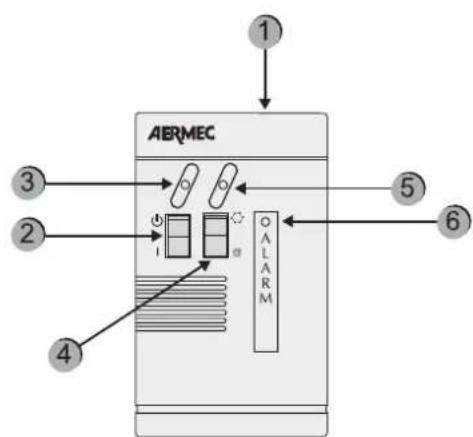
Component Description
| 1 simplified remote control panel PR3 | |
| 2 On/Off switch | |
| 3 | Yellow ON/OFF indicator light when the yellow led is on = ON |
| 4 | Shift to COOLING/HEATING operation mode * = cooling operation * = heat pump operation |
| 5 | Operation mode [bicColour indicator light] Blue indicator light = it is operating in cold mode Red indicator light = it is operating in heat pump mode |
| 6 Red indicator light: when on, it indicates alarm status | |
ALARMS10.
HISTORY OF SAFETIES
The safety management records the last Pre-alarms or Alarms occurred. This list is always active. Once the parameter is set, press the key to visualise the list and, for scrolling, press the arrow keys and . The following visualisations will appear on the display depending on whether the electronic card has or not the PGS accessory.
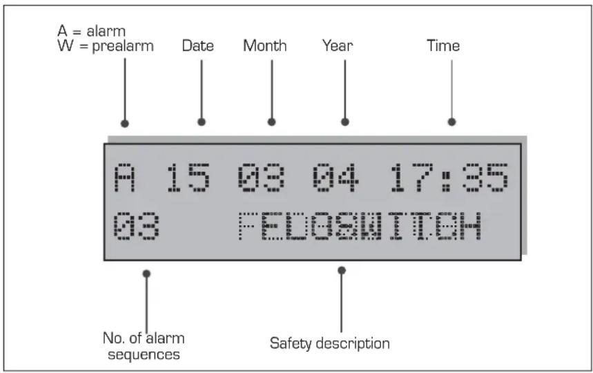
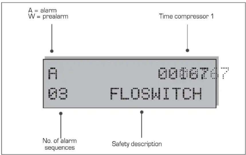
With PGS
In the first line, the first letter shows the intervention type (A for Alarm or W for Pre-alarm). Then, and only with PGS, the date [dd / mm / yy] and the time, on the right end, are indicated. If the PGS is not present, the compressor operation time shall be shown on the right end.
In the second line, the pair of figures shows the page number [from 01 to 999]
and occurred alarms and pre-alarms are listed at the centre of the line.
N.B. = although page enumeration is up to 999, all these pages cannot be saved. The number of saving operations [minimum 25] may change according to the type of memory with which the electronic card has been provided.
A10.1. larm history page format with PGS accessory
A10.2. larm history page format without PGS accessory
| VISUALISATION OF OCCURRED ALARMS | |||
| Alarm Water/air Water/water Description | |||
| Flow switch | ✓ | ✓ | Intervention of water differential pressure switch and/or flow switch |
| Cond. Pump/FL | ✓ | Intervention of condenser pump thermal protection/flow switch | |
| MT CP 1 | ✓ | ✓ | Intervention of compressor magneto-thermal 1 |
| MT CP 2 | ✓ | ✓ | Intervention of compressor magneto-thermal 2 |
| MT CP 1A | ✓ | ✓ | Intervention of compressor magneto-thermal 1A |
| MT CP 2A | ✓ | ✓ | Intervention of compressor magneto-thermal 2A |
| MT CP 1B | ✓ | ✓ | Intervention of compressor magneto-thermal 1B |
| MT CP 2B | ✓ | ✓ | Intervention of compressor magneto-thermal 2B |
| Low Pres. 1 | ✓ | ✓ | Intervention of pressure switch/low-pres. transducer circuit 1 |
| Low Pres. 2 | ✓ | ✓ | Intervention of pressure switch/low-pres. transducer circuit 2 |
| High Pres. 1 | ✓ | ✓ | Intervention of pressure switch/high-pres. transducer circuit 1 |
| High Pres. 2 | ✓ | ✓ | Intervention of pressure switch/high-pres. transducer circuit 2 |
| Antifreeze 1 | ✓ | ✓ | Intervention of antifreeze circuit 1 |
| Antifreeze 2 | ✓ | ✓ | Intervention of antifreeze circuit 2 |
| MT MV 1 | ✓ | Intervention of fan magneto-thermal circuit 1 | |
| MT MV 2 | ✓ | Intervention of fan magneto-thermal circuit 2 | |
| Probe 1 | ✓ | ✓ | Probe alarm circuit 1 |
| Probe 2 | ✓ | ✓ | Probe alarm circuit 2 |
| Monitor | ✓ | ✓ | Intervention of power supply control |
| Pumpdown 1 | ✓ | ✓ | Failure when unloading compressor cylinders of circuit 1 |
| Pumpdown 2 | ✓ | ✓ | Failure when unloading compressor cylinders of circuit 2 |
| Eprom | ✓ | ✓ | Abnormal operation of the electronic board |
| Ram | ✓ | ✓ | Abnormal operation of the electronic board |
| Flow Recovery | ✓ | ✓ | Flow switch of heat recovery circuit (only D and T versions) |
| MT MPOE 1 | ✓ | ✓ | Intervention of the evaporator pump magneto-thermal 1 |
| MT MPOE 2 | ✓ | Intervention of the evaporator pump magneto-thermal 2 | |
| MP MPOE 3 | ✓ | Intervention of the evaporator pump magneto-thermal 3 | |
| B.AG Evap1 | ✓ | ✓ | Evaporator outlet gas anti-freeze alarm 1 |
| B.AG Evap 2 | ✓ | ✓ | Evaporator outlet gas anti-freeze alarm 2 |

WARNING
Repeated and consecutive manual resets may seriously damage the unit.
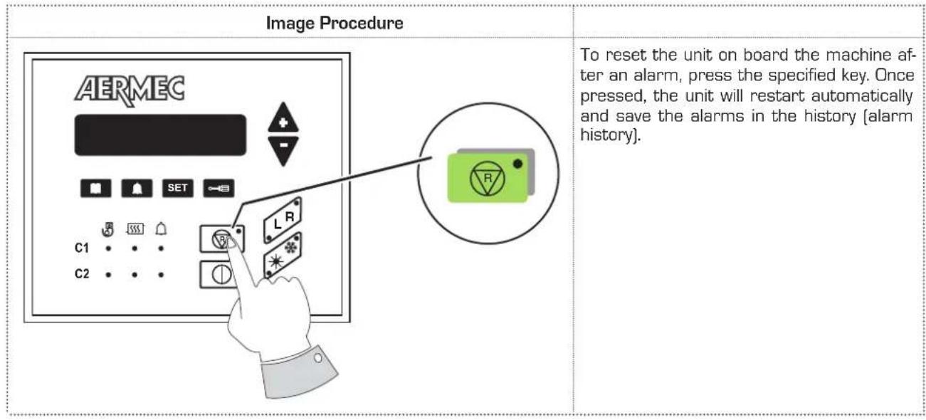
M10.3. anual reset on board the machine
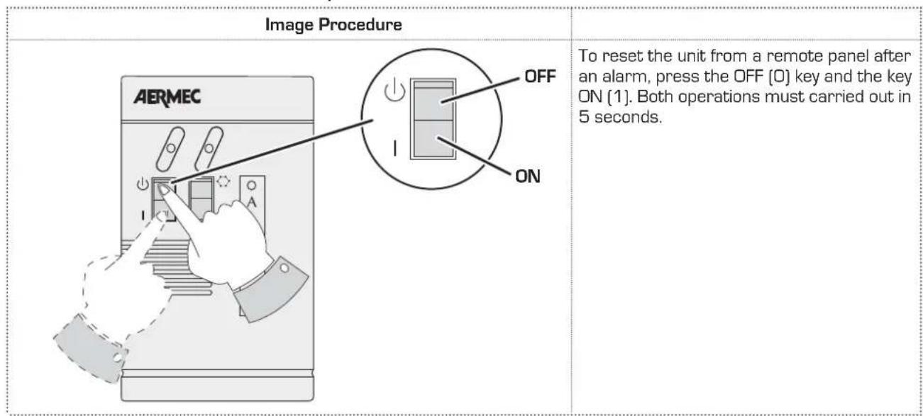
M10.4. anual reset from remote panel
Sommaire
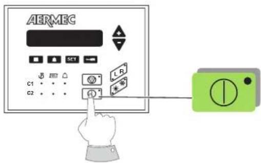
Image Procedure a adopter
ALLUMAGE :
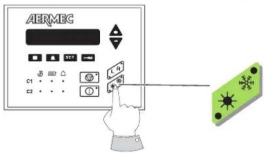
Image Procedure a adopter
Composant Description