HTP710 - Home theater audio system PIONEER - Free user manual and instructions
Find the device manual for free HTP710 PIONEER in PDF.
| Product Type | Home Cinema Audio System |
| Brand | PIONEER |
| Model | HTP710 |
| Channel Configuration | 5.1 channels (front left/right, center, surround left/right, subwoofer) |
| Amplifier | Multi-channel AV receiver integrated in subwoofer (SX-SWR2) |
| Power Supply | Mains 220-240 V ~ 50/60 Hz |
| HDMI Inputs | 3 inputs (BD/DVD, DVR/VCR, TV/SAT), 1 output (MONITOR OUT) |
| Digital Audio Inputs | 1 optical (TV/SAT), 2 coaxial |
| Analog Audio Inputs | 3 stereo pairs (BD/DVD, DVR/VCR, TV/SAT) |
| USB Input | 1 (front panel) |
| iPod/iPhone Input | 1 (front panel, cable included) |
| FM Tuner | FM with supplied wire antenna |
| Rear Surround Preamp Outputs | Yes (to add rear surround speakers) |
| Audio Functions | Dolby Digital, Dolby Pro Logic II, DTS, DTS-HD Master Audio, Auto Surround, Advanced Surround modes, Stream Direct, Sound Retriever, Phase Control, Acoustic Calibration EQ (MCACC) |
| Automatic Setup | Auto MCACC (multi-channel) with supplied microphone |
| Supplied Accessories | Remote control, MCACC microphone, digital optical cable, iPod cable, video cable, FM antenna, power cords, anti-slip pads, batteries, setup guide |
| Safety | Ventilation required (10 cm around), do not expose to water, unplug during storms, do not open |
| Maintenance | Clean with a soft, dry cloth, do not use abrasive products or solvents |
| Repairability | No user-serviceable parts; refer all servicing to qualified personnel |
| Operating Temperature | +5 °C to +35 °C, relative humidity < 85% |
Frequently Asked Questions - HTP710 PIONEER
User questions about HTP710 PIONEER
0 question about this device. Answer the ones you know or ask your own.
Ask a new question about this device
Download the instructions for your Home theater audio system in PDF format for free! Find your manual HTP710 - PIONEER and take your electronic device back in hand. On this page are published all the documents necessary for the use of your device. HTP710 by PIONEER.
USER MANUAL HTP710 PIONEER
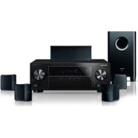
Audio/Video Multi-Channel Receiver Subwoofer
Audio/video multikanaals receiver subwoofer
S-DV595T
Speaker System Enceintes acoustiques Luidsprekersysteme
HTP-610
5.1 ch Surround System
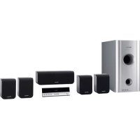
Audio/Video Multi-Channel Receiver Subwoofer
Audio/video multikanaals receiver subwoofer
S-SWR600
Speaker System Enceintes acoustiques Luidsprekersysteme
HTP-FS510
Front Surroud System
Surround Voor system
SX-SWR2
Audio/Video Multi-Channel Receiver Subwoofer
Audio/video multikanaals receiver subwoofer
S-SWR500FS
Speaker System Enceintes acoustiques Luidsprekersysteme
HTP-SB510
Front Surroud System
Audio/Video Multi-Channel Receiver Subwoofer
Audio/video multikanaals receiver subwoofer
S-SB510
Speaker System Enceintes acoustiques Luidsprekersysteme
Discover the benefits of registering your product online at
http://www.pioneer.co.uk (or http://www.pioneer.eu).
Operating Instructions
Mode d'emploi
Handleiding
IMPORTANT

The lightning flash with arrowhead symbol, within an equilateral triangle, is intended to alert the user to the presence of uninsulated "dangerous voltage" within the product's enclosure that may be of sufficient magnitude to constitute a risk of electric shock to persons.
CAUTION
RISK OF ELECTRIC SHOCK DO NOT OPEN
CAUTION:
TO PREVENT THE RISK OF ELECTRIC SHOCK,DO NOT REMOVE COVER (OR BACK).NO USER-SERVICEABLE PARTS INSIDE.REFER SERVICING TO QUALIFIED SERVICE PERSONNEL.

The exclamation point within an equilateral triangle is intended to alert the user to the presence of important operating and maintenance (servicing) instructions in the literature accompanying the appliance.
D3-4-2-1-1_A1_En
WARNING
This equipment is not waterproof. To prevent a fire or shock hazard, do not place any container filled with liquid near this equipment (such as a vase or flower pot) or expose it to dripping, splashing, rain or moisture.
D3-4-2-1-3_A1_En
WARNING
Before plugging in for the first time, read the following section carefully.
The voltage of the available power supply differs according to country or region. Be sure that the power supply voltage of the area where this unit will be used meets the required voltage (e.g., 230 V or 120 V) written on the rear panel.
D3-4-2-1-4*A1En
WARNING
To prevent a fire hazard, do not place any naked flame sources (such as a lighted candle) on the equipment.
D3-4-2-1-7a_A1_En
VENTILATION CAUTION
When installing this unit, make sure to leave space around the unit for ventilation to improve heat radiation (at least 10cm at top, 10cm at rear, and 10cm at each side).
WARNING
Slots and openings in the cabinet are provided for ventilation to ensure reliable operation of the product, and to protect it from overheating. To prevent fire hazard, the openings should never be blocked or covered with items (such as newspapers, table-cloths, curtains) or by operating the equipment on thick carpet or a bed.
D3-4-2-1-7b*A1En
Operating Environment
Operating environment temperature and humidity: +5^ to +35^ (+41^ to +95^) less than 85% RH (cooling vents not blocked) Do not install this unit in a poorly ventilated area, or in locations exposed to high humidity or direct sunlight (or strong artificial light)
D3-4-2-1-7c*A1_EN
If the AC plug of this unit does not match the AC outlet you want to use, the plug must be removed and appropriate one fitted. Replacement and mounting of an AC plug on the power supply cord of this unit should be performed only by qualified service personnel. If connected to an AC outlet, the cut-off plug can cause severe electrical shock. Make sure it is properly disposed of after removal. The equipment should be disconnected by removing the mains plug from the wall socket when left unused for a long period of time (for example, when on vacation).
D3-4-2-2-1a A1 En
CAUTION
The STANDBY/ON switch on this unit will not completely shut off all power from the AC outlet. Since the power cord serves as the main disconnect device for the unit, you will need to unplug it from the AC outlet to shut down all power. Therefore, make sure the unit has been installed so that the power cord can be easily unplugged from the AC outlet in case of an accident. To avoid fire hazard, the power cord should also be unplugged from the AC outlet when left unused for a long period of time (for example, when on vacation).
D3-4-2-2-2a*A1En
This product is for general household purposes. Any failure due to use for other than household purposes (such as long-term use for business purposes in a restaurant or use in a car or ship) and which requires repair will be charged for even during the warranty period.
K041_A1_En
Information for users on collection and disposal of old equipment and used batteries
(Symbol for equipment)

Symbol examples for batteries


Pb
These symbols on the products, packaging, and/or accompanying documents mean that used electrical and electronic products and batteries should not be mixed with general household waste.
For proper treatment, recovery and recycling of old products and used batteries, please take them to applicable collection points in accordance with your national legislation.
By disposing of these products and batteries correctly, you will help to save valuable resources and prevent any potential negative effects on human health and the environment which could otherwise arise from inappropriate waste handling.
For more information about collection and recycling of old products and batteries, please contact your local municipality, your waste disposal service or the point of sale where you purchased the items.
These symbols are only valid in the European Union.
For countries outside the European Union:
If you wish to discard these items, please contact your local authorities or dealer and ask for the correct method of disposal.
K058a_A1_En
Replacement and mounting of an AC plug on the power supply cord of this unit should be performed only by qualified service personnel.
IMPORTANT: THE MOULDED PLUG
This appliance is supplied with a moulded three pin mains plug for your safety and convenience. A 10 amp fuse is fitted in this plug. Should the fuse need to be replaced, please ensure that the replacement fuse has a rating of 10 amps and that it is approved by ASTA or BSI to BS1362.
Check for the ASTA mark on the BSI mark on the body of the fuse.
If the plug contains a removable fuse cover, you must ensure that it is refitted when the fuse is replaced. If you lose the fuse cover the plug must not be used until a replacement cover is obtained. A replacement fuse cover can be obtained from your local dealer.
If the fitted moulded plug is unsuitable for your socket outlet, then the fuse shall be removed and the plug cut off and disposed of safely. There is a danger of severe electrical shock if the cut off plug is inserted into any 13 amp socket.
If a new plug is to be fitted, please observe the wiring code as shown below. If in any doubt, please consult a qualified electrician.
IMPORTANT: The wires in this mains lead are coloured in accordance with the following code:
Blue: Neutral Brown:Live
As the colours of the wires in the mains lead of this appliance may not correspond with the coloured markings identifying the terminals in your plug, proceed as follows:
The wire which is coloured BLUE must be connected to the terminal which is marked with the letter N or coloured BLACK.
The wire which is coloured BROWN must be connected to the terminal which is marked with the letter L or coloured RED.
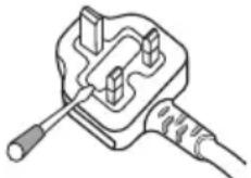
How to replace the fuse: Open the fuse compartment with a screwdriver and replace the fuse.
D3-4-2-1-2-2*A1_En
Manufactured under license from Dolby Laboratories. "Dolby", "Pro Logic", and the double-D symbol are trademarks of Dolby Laboratories.
Manufactured under license under U.S. Patent #s: 5,451,942; 5,956,674; 5,974,380; 5,978,762; 6,226,616; 6,487,535; 7,212,872; 7,333,929; 7,392,195; 7,272,567 & other U.S. and worldwide patents issued & pending. DTS and the Symbol are registered trademarks, & DTS-HD, DTS-HD Master Audio, and the DTS logos are trademarks of DTS, Inc. Product includes software. © DTS, Inc. All Rights Reserved.
1 Setup Guide (HTP-710)
What's in the box
Please confirm that the following items are all supplied.
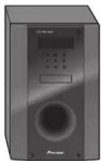
Receiver subwoofer (SX-SWR2) box

Receiver subwoofer x1

Optical digital cable x1

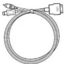
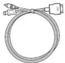
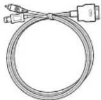
iPod cable x1

Microphone (for Auto MCACC setup) x1
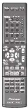
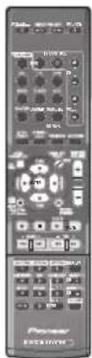
Remote control x1

Power cords x2

FM wire antenna x1
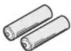
Dry cell batteries (AAA size IEC R03) x2

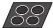
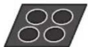
Large non-skid pads (for receiver subwoofer) x4

Video cable x1
Warranty card Operating instructions (This document)
Speakers (S-DV595T) box
A
Front/surround speakers x4
C
Speaker stand bases x4

Small non-skid pads (for speaker stand bases) x16
Connection


1 Setup Guide (HTP-610)
What's in the box
Please confirm that the following items are all supplied.
Receiver subwoofer (SX-SWR2) box
Receiver subwoofer x1

Optical digital cable x1
iPod cable x1

Microphone (for Auto MCACC setup) x1
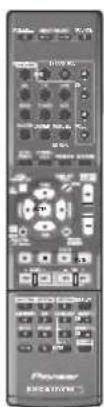
Remote control x1

Power cords x2

FM wire antenna x1
Dry cell batteries (AAA size IEC R03) x2
Large non-skid pads (for receiver subwoofer) x4

Video cable x1
Warranty card Operating instructions (This document)
Speakers (S-SWR600) box
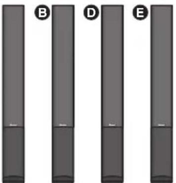
A
Front speakers x2
B

C
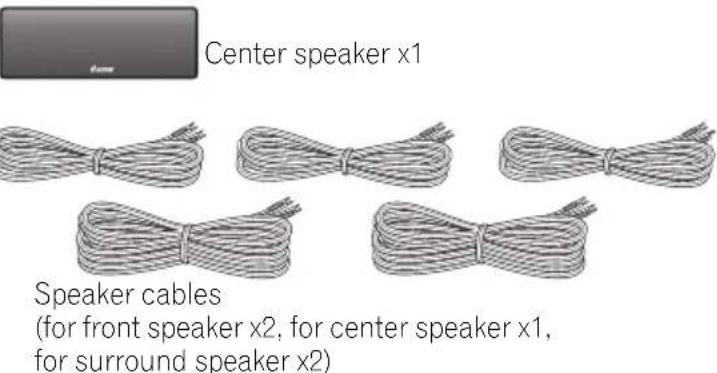
Center speakers x2


Surround speakers x2

Speaker cables (for front speaker x2, for center speaker x1, for surround speaker x2)
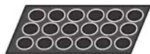
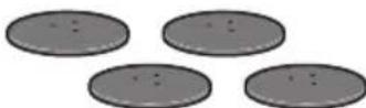
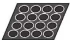
Small non-skid pads (for speaker stand bases) x18
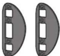
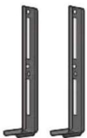
Brackets x2


Mounting brackets x6

Screws x8
Connection

1 Setup Guide (HTP-FS510)
What's in the box
Please confirm that the following items are all supplied.
Receiver subwoofer (SX-SWR2) box

Receiver subwoofer x1

Optical digital cable x1
iPod cable x1

Microphone (for Auto MCACC setup) x1
Remote control x1

Power cords x2

FM wire antenna x1
Dry cell batteries (AAA size IEC R03) x2
Large non-skid pads (for receiver subwoofer) x4

Video cable x1
Warranty card Operating instructions (This document)
Speakers (S-SWR500FS) box

A
B
Front speakers x2
Poles x2


Speaker cables x2

Screws (short) x8
Speaker stand bases x2

Gaskets x2
Screws (long) x4
Connection

1 Setup Guide (HTP-SB510)
What's in the box
Please confirm that the following items are all supplied.
Receiver subwoofer (SX-SWR2) box
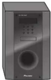
Receiver subwoofer x1

Optical digital cable x1
iPod cable x1

Microphone (for Auto MCACC setup) x1
Remote control x1


Power cords x2

FM wire antenna x1
Dry cell batteries (AAA size IEC R03) x2
Large non-skid pads (for receiver subwoofer) x4

Video cable x1
Warranty card Operating instructions (This document)
Speakers (S-SB510) box

Speaker x1

Speaker cable x1

Speaker stands × 2

Small non-skid pads (for speaker stands/for speaker) x10

Screws x2
Connection


12
For enjoying your self
(MCACC)
For enjoying your self (MCACC)
1
4
5
2
6
3
③ Home theater
1
BD/DVDRadio
2
3
4
1
2
3


Thank you for buying this Pioneer product.
Please read through these operating instructions so that you will know how to operate your model properly. After you have finished reading the instructions, put them in a safe place for future reference.
Contents
Setup Guide
HTP-710. 4
HTP-610. 6
HTP-FS510 8
HTP-SB510. 10
For enjoying your self (MCACC)...12
Home theater. 13
01 Speaker Setup (HTP-710)
Safety precautions when setting up. 16
Home theater sound setup 16
Preparing the speakers. 16
Securing your front and surround speakers 18
Wall mounting the center speaker. 18
Before mounting. 18
Additional notes on speaker placement. .19
01 Speaker Setup (HTP-610)
Safety precautions when setting up. 20
Home theater sound setup 20
Preparing the speakers. 20
Wall mounting the speakers 22
Before mounting. 22
Additional notes on speaker placement. .23
01 Speaker Setup (HTP-FS510)
Safety precautions when setting up. 24
Home theater sound setup 24
Preparing the speakers 24
Wall mounting the front speakers 26
Before mounting. 26
Attaching the speakers 27
Additional notes on speaker placement. .27
For Enhanced Sound Quality. 27
01 Speaker Setup (HTP-SB510)
Safety precautions when setting up 28
Home theater sound setup 28
Preparing the speakers 28
Wall mounting the speaker 30
Before mounting. 30
Additional notes on speaker placement 31
For Enhanced Sound Quality. 31
02 Connecting up
Rear panel. 32
Making cable connections 33
About video outputs connection 33
HDMI cables. 33
Analog audio cables 34
Digital audio cables 34
Connect your TV (For TV audio) 35
Connecting your TV and playback components 36
Connecting using HDMI 36
Connecting your component with no HDMI terminal 37
Connecting an HDD/DVD recorder, VCR and other video sources 38
Connecting a satellite receiver or other digital set-top box 39
Connecting other audio components 40
Connecting to the front panel video terminal 41
Connecting an iPod/iPhone 41
Connecting a USB device 42
Connecting the FM antenna 42
Connecting external antennas 42
Use the PRE OUT outputs to connect the surround back speakers 43
Plugging in the system 43
03 Controls and displays
Front panel. 44
Display. 45
Remote control 47
Putting the batteries in the remote control 50
Using the remote control. 50
04 Getting started
Automatically setting up for surround sound (MCACC) 51
Other problems when using the Auto MCACC Setup 53
Basic operation 54
Choosing the input signal 54
05 iPod/USB playback
Playing an iPod 55
iPod playback 55
Watching photos and video content 57
About iPod/Phone 57
Playing a USB device 58
Basic playback controls. 58
Compressed audio compatibility 59
06 Using the tuner
Listening to the radio 60
Improving FM stereo sound 60
Saving station presets 60
Listening to station presets 61
Naming preset stations 61
An introduction to RDS 61
Searching for RDS programs. 62
Displaying RDS information 62
07 Listening to your system
Selecting Listening mode. 63
Auto playback 63
Listening in surround sound 63
Using the Advanced surround effects.. 64
Listening in stereo 64
Using Front Stage Surround Advance 65
Using Stream Direct 65
Using the Sound Retriever 65
Listening with Acoustic Calibration EQ . . 66
Better sound using Phase Control 66
Functions when surround back speakers are connected 67
Surround sound mode. 67
Using surround back channel processing... 68
Setting the Up Mix function 68
Setting the Audio options. 69
08 The System Setup menu
Using the System Setup menu 72
Manual speaker setup. 72
Speaker Setting. 73
Channel Level. 73
Speaker Distance 74
09 Controlling the rest of your system
Setting the remote to control other components 75
Selecting preset codes directly. 75
Clearing all the remote control settings. .75
Controls for TVs. 76
Controls for other components. 77
Preset Code List 79
10 Additional information
Troubleshooting. 84
HDMI .86
Important information regarding the HDMI connection .87
iPod messages .87
USB messages 88
Resetting the main unit. 88
Specifications. 88
SX-SWR2 Receiver subwoofer. 88
S-DV595T Speaker system (HTP-710). .89
S-SWR600 Speaker system (HTP-610) .89
S-SWR500FS Speaker system (HTP-FS510) .90
S-SB510 Speaker system (HTP-SB510) . .90
Cleaning the unit 90
Chapter 1-1
Speaker Setup (HTP-710)
Safety precautions when setting up
When assembling the speakers, lay them down flat on their side to avoid accidents or injury. Make sure to use a stable surface when assembling, setting up, and placing the speakers.
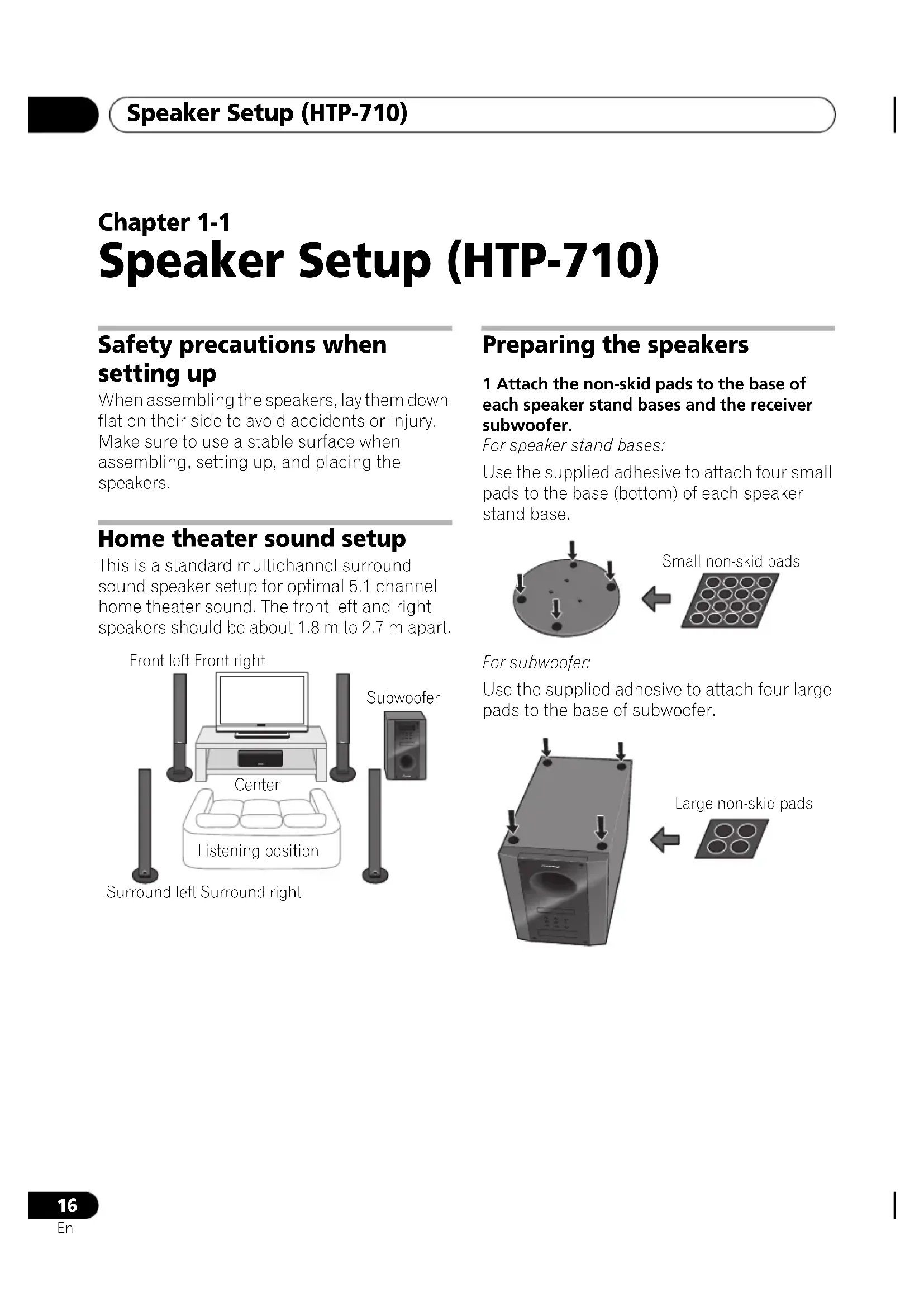
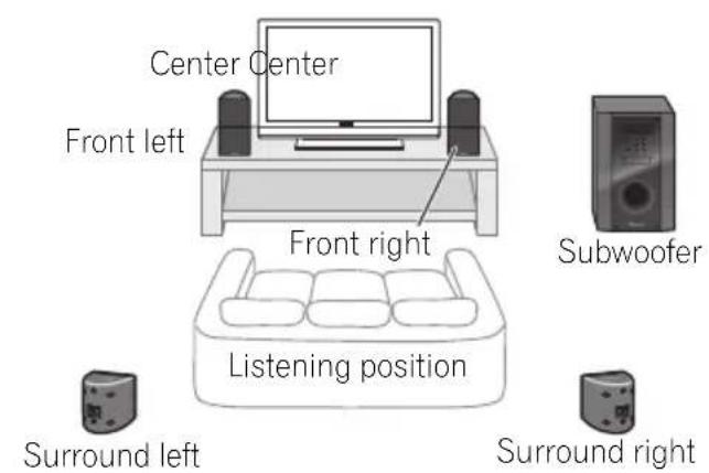
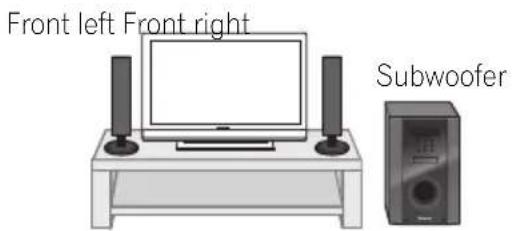
Home theater sound setup
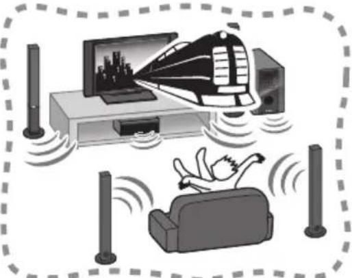
This is a standard multichannel surround sound speaker setup for optimal 5.1 channel home theater sound. The front left and right speakers should be about 1.8m to 2.7m apart.
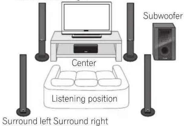
Front left Front right
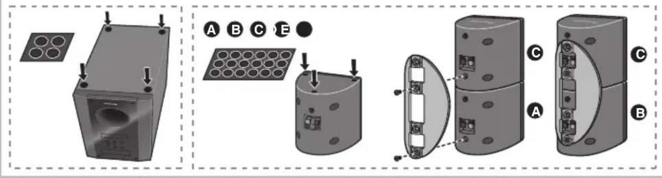
Preparing the speakers
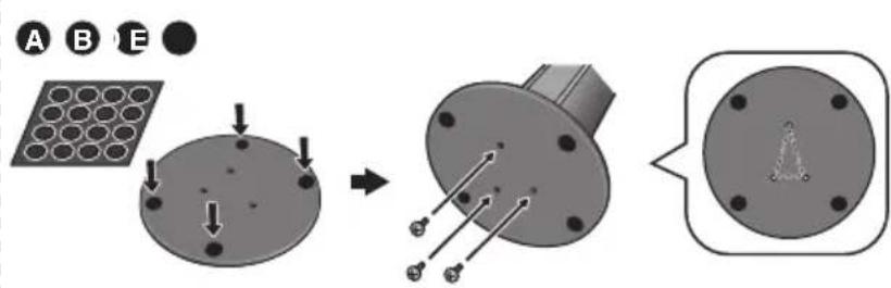
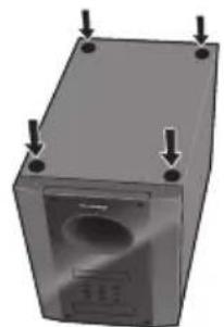
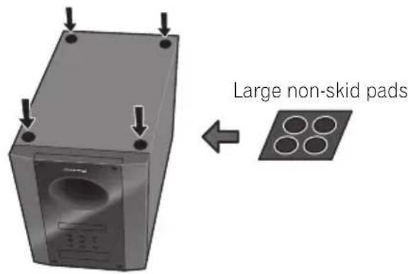
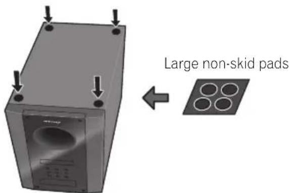
1 Attach the non-skid pads to the base of each speaker stand bases and the receiver subwoofer.
For speaker stand bases:
Use the supplied adhesive to attach four small pads to the base (bottom) of each speaker stand base.

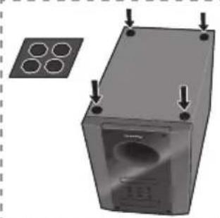
For subwoofer:
Use the supplied adhesive to attach four large pads to the base of subwoofer.
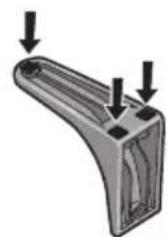
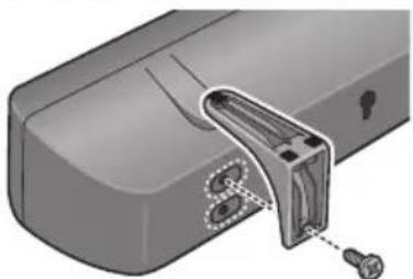
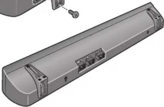
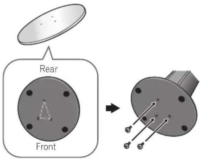
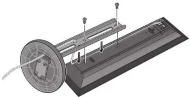
2 Attach the speaker stand bases to the stems using the screws provided.
Once you have aligned the stem and base, secure with the small screws at the points shown below. Note that the speaker should face in the direction of the base of the isosceles triangle.

CAUTION
- Be careful not to tighten screws excessively.
- If excessive force is used to tighten screws, the threads of screw and/or nut may be damaged. Use a middle-sized manual screwdriver during assembly.
- Do not use power screwdrivers or oversized screwdrivers that may exert excessive force on the screws and nuts.
- Confirm that no foreign matter is stuck to the stand base or the tall speaker during assembly.
- If the unit is assembled with foreign matter stuck between the stand base and the tall speaker the unit may not be assembled securely, resulting in tipping or falling.
- Do not stand on the speaker stand base of the tall speaker to push or swing the speaker. The speaker may fall and break, or someone may be injured. Pay special attention to children.
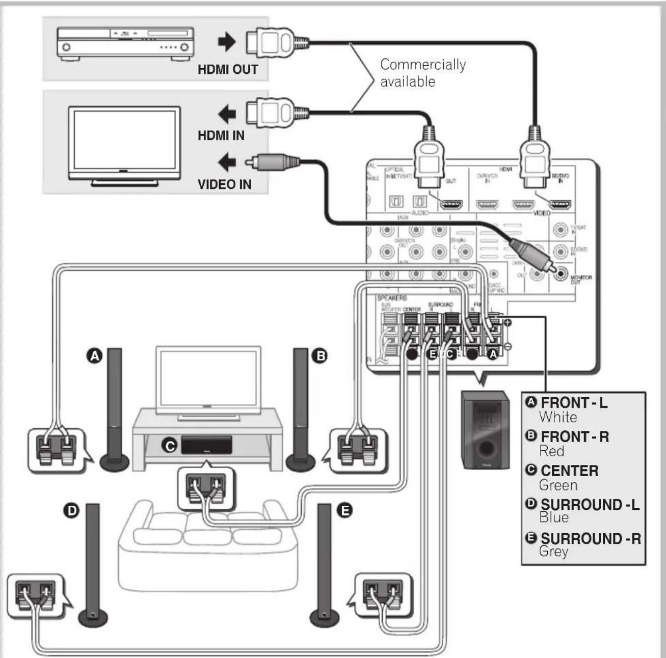
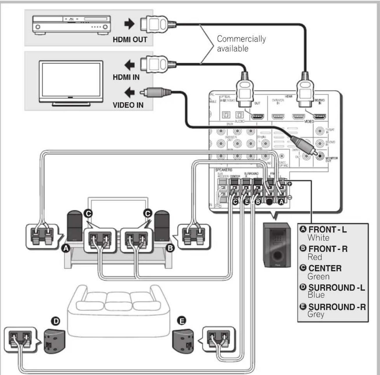
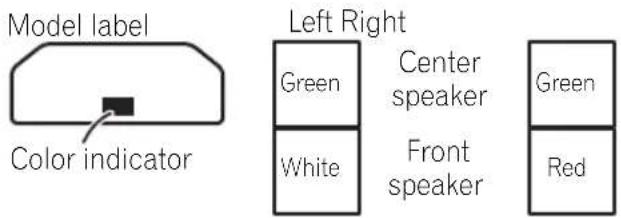
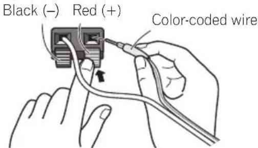
3 Connect each speaker.
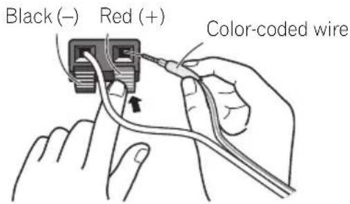
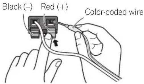
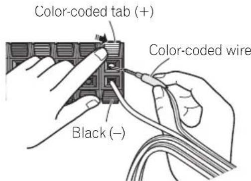
Connect the wires to the speaker. Each speaker in the illustration can be identified by means of the color-coded indicator provided on the rear-surface label.
Front left: White
Front right: Red
Center:Green
Surround left: Blue
Surround right: Gray
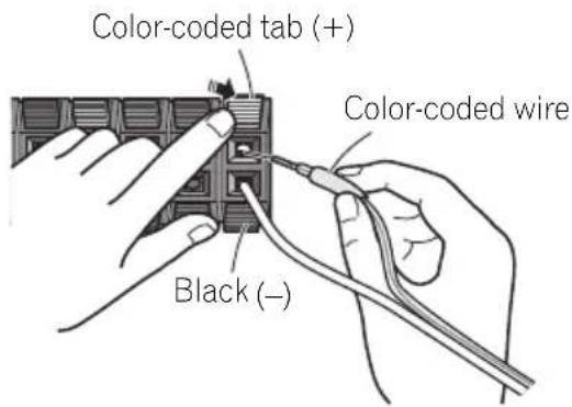
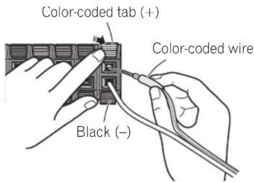
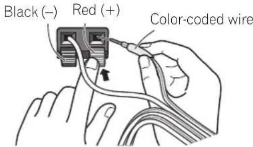
Match the color-coded wire with the color indicator on the label, then insert the color-coded wire into the red (+) side and the other wire into the black (-) side.
Connect the other end to the color-coded speaker terminals on the rear of the receiver subwoofer.

CAUTION
These speaker terminals carry HAZARDOUS LIVE voltage. To prevent the risk of electric shock when connecting or disconnecting the speaker cables, disconnect the power cord before touching any uninsulated parts.
- Do not connect any speakers other than those supplied to this system.
- Do not connect the supplied speakers to any amplifier other than the one supplied with this system. Connection to any other amplifier may result in malfunction or fire.
- After connecting the plugs, pull lightly on the cables to make sure that the ends of the cables are securely connected to the terminals. Poor connections can create noise and interruptions on the sound.
- If the cable's wires happen to be pushed out of the terminals, allowing the wires to come into contact with each other, it places an excessive additional load on the amp. This may cause the amp to stop functioning, and may even damage the amp.
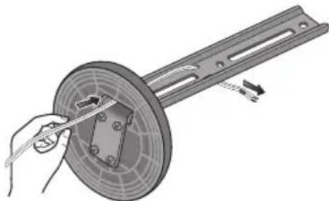
Securing your front and surround speakers
- Secure each of the front and surround speakers using the plastic catch provided.
Screw two supporting hooks into the wall behind the speaker. Pass a thick cord around the hooks and through the plastic catch so that the speaker is stabilized (make sure to test that it supports the weight of the speaker). After installing, make sure the speaker is securely fixed.


CAUTION
- The plastic catch is not a mounting fixture, and the speaker should not be hung directly from the wall using this catch. Always use a cord when stabilizing the speaker.
- Pioneer disclaims all responsibility for any losses or damage resulting from improper assembly, installation, insufficient strength of the installation materials, misuse, or natural disasters.
- When placing this unit, ensure that it is firmly secured and avoid areas where it may be likely to fall and cause injury in the event of a natural disaster (such as an earthquake).
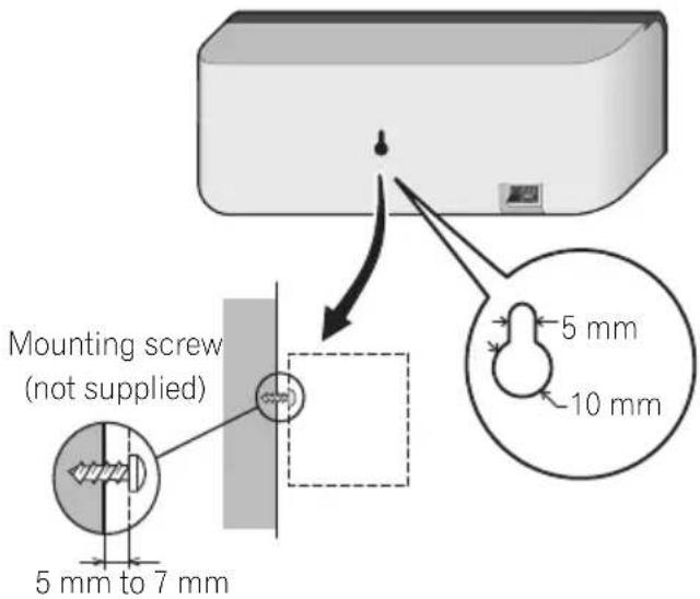
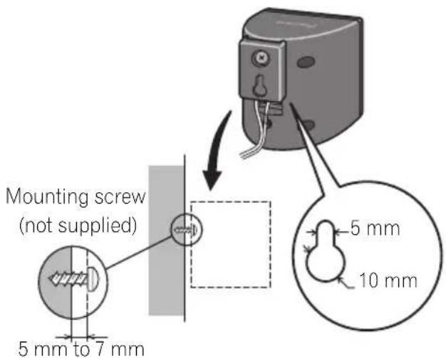
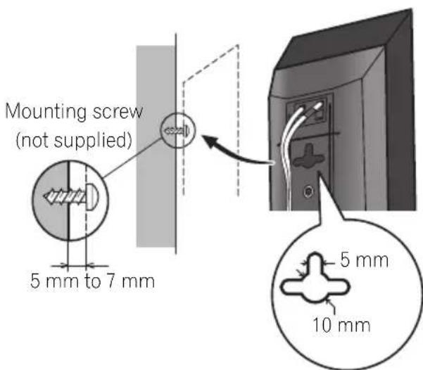
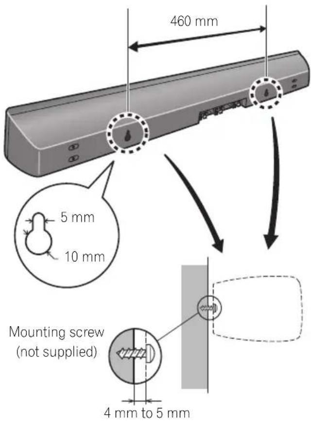
Wall mounting the center speaker
The center speaker have a mounting hole which can be used to mount the speaker on the wall.
Before mounting
-
Remember that the speaker system is heavy and that its weight could cause the screws to work loose, or the wall material to fail to support it, resulting in the speaker falling. Make sure that the wall you intend to mount the speakers on is strong enough to support them. Do not mount on plywood or soft surface walls.
-
Mounting screws are not supplied. Use screws suitable for the wall material and support the weight of the speaker.

CAUTION
If you are unsure of the qualities and strength of the wall, consult a professional for advice.
- Pioneer is not responsible for any accidents or damage that result from improper installation.
Additional notes on speaker placement
Install the main front left and right speakers at an equal distance from the TV.
- Install the surround speakers slightly above ear level for optimum effect.
- Televisions supporting 3D display transmit signals to the 3D glasses worn by the viewer. In order to view 3D images, consult the television's Operating Instructions and install the center speaker so that it does not block the television's 3D signal transmitter.
Precautions:
- When installing the center speaker on top of the TV, be sure to secure it with tape or some other suitable means. Otherwise, the speaker may fall from the TV due to external shocks such as earthquakes, endangering those nearby or damaging the speaker.
- Make sure that all the bare speaker wire is twisted together and inserted fully into the speaker terminal. If any of the bare speaker wire touches the back panel it may cause the power to cut off as a safety measure.
- The front, center and surround speakers supplied with this system are magnetically shielded. However, depending on the installation location, color distortion may occur if the speaker is installed extremely close to the screen of a television set. If this case happens, turn the power switch of the television set OFF, and turn it ON after 15 min. to 30 min. If the problem persists, place the speaker system away from the television set.
- The subwoofer is not magnetically shielded and so should not be placed near a TV or monitor. Magnetic storage media (such as floppy discs and tape or video cassettes) should also not be kept close to the subwoofer.
- Do not attach the front/surround speakers and subwoofer to a wall or ceiling. They may fall off and cause injury.
- Do not stand on the speaker stand base of the tall speaker to push or swing the speaker. The speaker may fall and break, or someone may be injured. Pay special attention to children.
Chapter 1-2
Speaker Setup (HTP-610)
Safety precautions when setting up
When assembling the speakers, lay them down flat on their side to avoid accidents or injury. Make sure to use a stable surface when assembling, setting up, and placing the speakers.
If the speakers are to be used in a stacked configuration, always use the provided brackets to secure them together (page 21).
Home theater sound setup
This is a standard multichannel surround sound speaker setup for optimal 5.1 channel home theater sound. The front left and right speakers should be about 1.8m to 2.7m apart.
*When center speakers are placed in the center.

Preparing the speakers
1 Attach the non-skid pads to the base of each speakers and the receiver subwoofer.
For front, center and surround speakers:
Use the supplied adhesive to attach three pads to the base (bottom) of each speaker.

For subwoofer:
Use the supplied adhesive to attach four large pads to the base of subwoofer.

2 (When mounting center speakers to right and left) Stack the speakers and fix with the bracket.
Each speaker is provided with a color-coded indicator on the model label on the rear side to assist identification. Refer to the color indicators and install the speakers correctly.
As shown in the illustration, stack the speakers. Align the bracket with the respective upper and lower screw holes as shown in each figure below and fasten the screws securely.
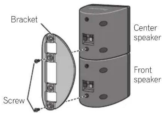
CAUTION
- Do not attempt to carry the speakers when they are connected with the bracket. Doing so may cause damage to the bracket or worsen damage to the bracket and speakers in the event they are dropped.
3 Connect each speaker.
Connect the wires to the speaker. Each speaker in the illustration can be identified by means of the color-coded indicator provided on the rear-surface label.
Front left: White
Front right: Red
Center:Green
Surround left: Blue
Surround right: Gray
Match the color-coded wire with the color indicator on the label, then insert the color-coded wire into the red (+) side and the other wire into the black (-) side.
- When connecting the center speakers, connect the Y-cable dual end to the two center speakers in the same way.
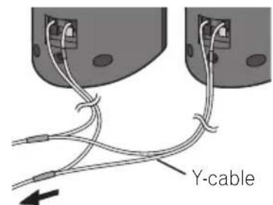
To receiver subwoofer
Speaker Setup (HTP-610)
Connect the other end to the color-coded speaker terminals on the rear of the receiver subwoofer.

CAUTION
These speaker terminals carry HAZARDOUS LIVE voltage. To prevent the risk of electric shock when connecting or disconnecting the speaker cables, disconnect the power cord before touching any uninsulated parts.
- Do not connect any speakers other than those supplied to this system.
- Do not connect the supplied speakers to any amplifier other than the one supplied with this system. Connection to any other amplifier may result in malfunction or fire.
- After connecting the plugs, pull lightly on the cables to make sure that the ends of the cables are securely connected to the terminals. Poor connections can create noise and interruptions on the sound.
- If the cable's wires happen to be pushed out of the terminals, allowing the wires to come into contact with each other, it places an excessive additional load on the amp. This may cause the amp to stop functioning, and may even damage the amp.
Wall mounting the speakers
All the speakers (except the subwoofer, which should be placed on the ground) have holes for mounting brackets, and depending on the speaker setup you choose, you can wall-mount the front, center and surround speakers.
- Make sure to tighten the supplied screw as securely as possible when attaching the bracket to the back of the speaker.
Before mounting
- Remember that the speaker system is heavy and that its weight could cause the screws to work loose, or the wall material to fail to support it, resulting in the speaker falling. Make sure that the wall you intend to mount the speakers on is strong enough to support them. Do not mount on plywood or soft surface walls.
- Mounting screws are not supplied. Use screws suitable for the wall material and support the weight of the speaker.

CAUTION
If you are unsure of the qualities and strength of the wall, consult a professional for advice.
- Pioneer is not responsible for any accidents or damage that result from improper installation.
Screw (supplied)
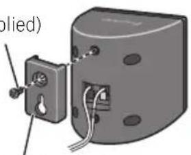
Mounting bracket (supplied)
Additional notes on speaker placement
Install the main front left and right speakers at an equal distance from the TV.
-
Install the surround speakers slightly above ear level for optimum effect.
-
Televisions supporting 3D display transmit signals to the 3D glasses worn by the viewer. In order to view 3D images, consult the television's Operating Instructions and install the center speaker so that it does not block the television's 3D signal transmitter.
Precautions:
- When installing the center speaker on top of the TV, be sure to secure it with tape or some other suitable means. Otherwise, the speaker may fall from the TV due to external shocks such as earthquakes, endangering those nearby or damaging the speaker.
- The front, center and surround speakers supplied with this system are magnetically shielded. However, depending on the installation location, color distortion may occur if the speaker is installed extremely close to the screen of a television set. If this case happens, turn the power switch of the television set OFF, and turn it ON after 15 min. to 30 min. If the problem persists, place the speaker system away from the television set.
- The subwoofer is not magnetically shielded and so should not be placed near a TV or monitor. Magnetic storage media (such as floppy discs and tape or video cassettes) should also not be kept close to the subwoofer.
- Do not attach the subwoofer to the wall or ceiling. They may fall off and cause injury.
Chapter 1-3
Speaker Setup (HTP-FS510)
Safety precautions when setting up
When assembling the speakers, lay them down flat on their side to avoid accidents or injury. Make sure to use a stable surface when assembling, setting up, and placing the speakers.
Home theater sound setup
This is a standard speaker setup. The front left and right speakers should be about 1.8 m to 2.7 m apart.
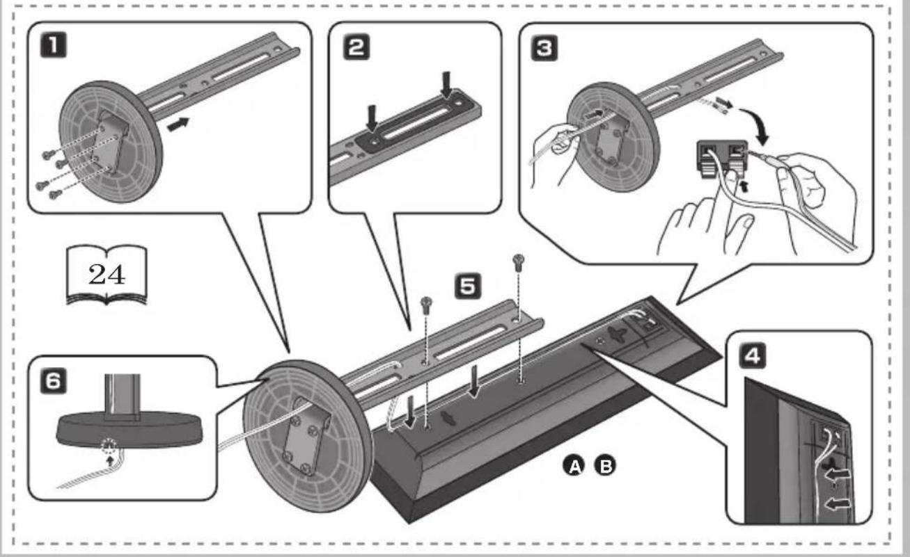
Preparing the speakers
1 Attach the non-skid pads to the base of receiver subwoofer.
Use the supplied adhesive to attach four pads to the base of subwoofer.

2 Insert the pole from the holes behind the base and secure with the 4 screws.

CAUTION
- Be careful not to tighten screws excessively.
- If excessive force is used to tighten screws, the threads of screw and/or nut may be damaged. Use a middle-sized manual screwdriver during assembly.
- Do not use power screwdrivers or oversized screwdrivers that may exert excessive force on the screws and nuts.
- Confirm that no foreign matter is stuck to the stand base or the tall speaker during assembly.
- If the unit is assembled with foreign matter stuck between the stand base and the tall speaker the unit may not be assembled securely, resulting in tipping or falling.
3 Affix the gasket to the pole.
Affix the gasket to the surface of the pole where the speaker will be mounted.
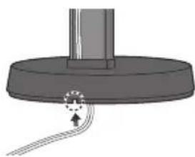
4 Insert the speaker cable from the hole behind the base through to the pole.
5 Connect each speaker.
Connect the wires to the speaker. Each speaker in the illustration can be identified by means of the color-coded indicator provided on the rear-surface label.
Front left: White
Front right: Red
Match the color-coded wire with the color indicator on the label, then insert the color-coded wire into the red (+) side and the other wire into the black (-) side.
Connect the other end to the color-coded speaker terminals on the rear of the receiver subwoofer.
- When connections are completed, secure the speaker cables. Fix the cables to the groove in the speakers.


CAUTION
These speaker terminals carry HAZARDOUS LIVE voltage. To prevent the risk of electric shock when connecting or disconnecting the speaker cables, disconnect the power cord before touching any uninsulated parts.
- Only those speakers supplied, or purchased as an officially supported option, should be connected to this system.
- Do not connect the supplied speakers to any amplifier other than the one supplied with this system. Connection to any other amplifier may result in malfunction or fire.
- After connecting the plugs, pull lightly on the cables to make sure that the ends of the cables are securely connected to the terminals. Poor connections can create noise and interruptions on the sound.
- If the cable's wires happen to be pushed out of the terminals, allowing the wires to come into contact with each other, it places an excessive additional load on the amp. This may cause the amp to stop functioning, and may even damage the amp.
6 Secure the speaker and the pole with 2 screws.
- Confirm that the speaker cable does not become pinched between the pole and the speaker.
- Put the speaker cable in the back of the base of the stand.
Wall mounting the front speakers
The front speakers have a mounting hole which can be used to mount the speaker on the wall.
Before mounting
- Remember that the speaker system is heavy and that its weight could cause the screws to work loose, or the wall material to fail to support it, resulting in the speaker falling. Make sure that the wall you intend to mount the speakers on is strong enough to support them. Do not mount on plywood or soft surface walls.
- Mounting screws are not supplied. Use screws suitable for the wall material and support the weight of the speaker.

CAUTION
If you are unsure of the qualities and strength of the wall, consult a professional for advice.
- Pioneer is not responsible for any accidents or damage that result from improper installation.
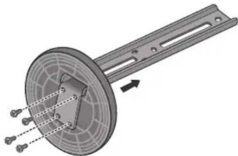
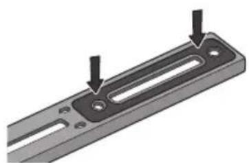
Attaching the speakers
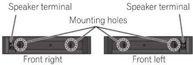
The front speaker can be hung vertically or horizontally on the wall. Use one hole to hang it vertically and two holes to hang it horizontally.
When installing the speaker horizontally, set it up so that the speaker terminal on the back side of the speaker is on the outside on the end of the surface, farthest away from the other speaker.
Additional notes on speaker placement
- Install the front left and right speakers at an equal distance from the TV.
Precautions:
- Make sure that all the bare speaker wire is twisted together and inserted fully into the speaker terminal. If any of the bare speaker wire touches the back panel it may cause the power to cut off as a safety measure.
-
The front speakers supplied with this system are magnetically shielded. However, depending on the installation location, color distortion may occur if the speaker is installed extremely close to the screen of a television set. If this case happens, turn the power switch of the television set OFF, and turn it ON after 15 min. to 30 min. If the problem persists, place the speaker system away from the television set.
-
The subwoofer is not magnetically shielded and so should not be placed near a TV or monitor. Magnetic storage media (such as floppy discs and tape or video cassettes) should also not be kept close to the subwoofer.
- Do not attach the subwoofer to a wall or ceiling. They may fall off and cause injury.
For Enhanced Sound Quality
A home theater system can be easily constructed using just the front (right/left) speakers and the subwoofer of this set, but by adding optional S-SWR5CR speaker systems, you can enjoy genuine 5.1 channel surround sound.
Take the following points into account when connecting the optional speaker systems:
- When the contents of these Operating Instructions from chapter 2 on describe a specific model, use those portions dealing with the HTP-610.
- For information regarding the installation and connection of optional speaker systems, consult the information provided with the optional speaker systems, together Speaker Setup (HTP-610) on page 20 portion of these Operating Instructions.
- See Automatically setting up for surround sound (MCACC) on page 51 to set up your system again using MCACC.
Chapter 1-4
Speaker Setup (HTP-SB510)
Safety precautions when setting up
When assembling the speakers, lay them down flat on their side to avoid accidents or injury. Make sure to use a stable surface when assembling, setting up, and placing the speakers.
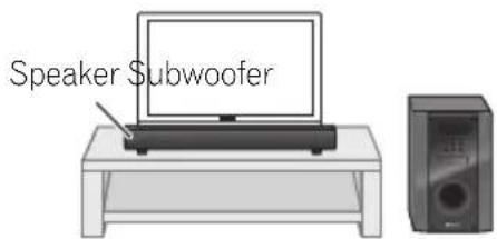
Home theater sound setup
The speaker should be installed below (in front of) the TV. The height of the speaker stands can be adjusted, or the speaker can be installed without using the stands at all.
- The speaker and subwoofer are not magnetically shielded and so should not be used with CRT TV.
Preparing the speakers
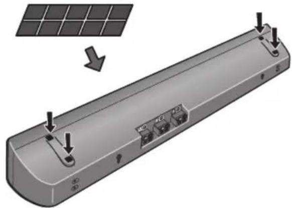
1 Attach the non-skid pads to the base of each speaker stands and the receiver subwoofer.
For speaker stands:
Use the supplied adhesive to attach three small pads to the base (bottom) of each speaker stand.

For subwoofer:
Use the supplied adhesive to attach four large pads to the base of subwoofer.
Speaker Setup (HTP-SB510)
If you decide not to use the speaker stands, use the supplied adhesive to attach four small pads to the base of the speaker.
Small non-skid pads
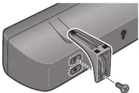
2 Attach the speaker stand bases to the speaker.
Attach both right and left speaker stands to the rear of the speaker. The height of the speaker stands can be adjusted in two levels; select the height you prefer, and fix in position.

CAUTION
- Be careful not to tighten screws excessively.
- If excessive force is used to tighten screws, the threads of screw may be damaged. Use a middle-sized manual screwdriver during assembly.
- Do not use power screwdrivers or oversized screwdrivers that may exert excessive force on the screws.
-
Confirm that no foreign matter is stuck to the stand or the speaker during assembly.
-
If the unit is assembled with foreign matter stuck between the stand and the speaker the unit may not be assembled securely, resulting in tipping or falling.
3 Connect each speaker.
Connect the wires to the speaker.
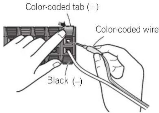
The rear of the speaker has channel terminals (Right/Center/Left), together with color-coded labels.
Front left: White
Front right: Red
Center:Green
Match the color-coded wire with the color indicator on the label, then insert the color-coded wire into the red (+) side and the other wire into the black (-) side.
Connect the other end to the color-coded speaker terminals on the rear of the receiver subwoofer.

CAUTION
These speaker terminals carry HAZARDOUS LIVE voltage. To prevent the risk of electric shock when connecting or disconnecting the speaker cables, disconnect the power cord before touching any uninsulated parts.
- Do not connect any speakers other than those supplied to this system.
- Do not connect the supplied speaker to any amplifier other than the one supplied with this system. Connection to any other amplifier may result in malfunction or fire.
- After connecting the plugs, pull lightly on the cables to make sure that the ends of the cables are securely connected to the terminals. Poor connections can create noise and interruptions on the sound.
- If the cable's wires happen to be pushed out of the terminals, allowing the wires to come into contact with each other, it places an excessive additional load on the amp. This may cause the amp to stop functioning, and may even damage the amp.
Wall mounting the speaker
The speaker have the mounting holes which can be used to mount the speaker on the wall.
Before mounting
- Remember that the speaker system is heavy and that its weight could cause the screws to work loose, or the wall material to fail to support it, resulting in the speaker falling. Make sure that the wall you intend to mount the speaker on is strong enough to support them. Do not mount on plywood or soft surface walls.
- Mounting screws are not supplied. Use screws suitable for the wall material and support the weight of the speaker.

CAUTION
If you are unsure of the qualities and strength of the wall, consult a professional for advice.
- Pioneer is not responsible for any accidents or damage that result from improper installation.
- When mounting the speaker on a wall, install it so that it is parallel to the floor.
- When mounting the speaker on a wall, do not attach the accessory speaker stands.
Additional notes on speaker placement
- Install the speaker below the TV, in the center position.
- Televisions supporting 3D display transmit signals to the 3D glasses worn by the viewer. In order to view 3D images, consult the television's Operating Instructions and install the speaker so that it does not block the television's 3D signal transmitter.
Precautions:
- Do not rest the speaker on the TV itself.
- Make sure that all the bare speaker wire is twisted together and inserted fully into the speaker terminal. If any of the bare speaker wire touches the back panel it may cause the power to cut off as a safety measure.
- The speaker and subwoofer are not magnetically shielded and so should not be placed near a TV or monitor. Magnetic storage media (such as floppy discs and tape or video cassettes) should also not be kept close to the speaker and subwoofer.
- Do not attach the subwoofer to a wall or ceiling. They may fall off and cause injury.
For Enhanced Sound Quality
A home theater system can be easily constructed using just the speaker and the subwoofer of this set, but by adding optional SSB5R speaker systems, you can enjoy genuine 5.1 channel surround sound.
Take the following points into account when connecting the optional speaker systems:
- When the contents of these Operating Instructions from chapter 2 on describe a specific model, use those portions dealing with the HTP-610.
- For information regarding the installation and connection of optional speaker systems, consult the information provided with the optional speaker systems, together Speaker Setup (HTP-610) on page 20 portion of these Operating Instructions.
- See Automatically setting up for surround sound (MCACC) on page 51 to set up your system again using MCACC.
Chapter 2 Connecting up
Rear panel
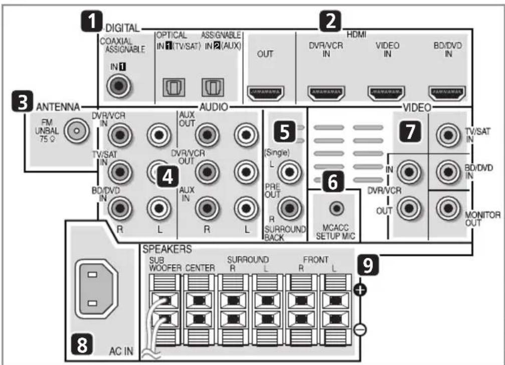
1 Coaxial/Optical digital audio inputs (x3)
Use the supplied optical digital cable to connect the DIGITAL OPTICAL IN 1 (TV/SAT) input to the television's optical digital output terminal.
Use for digital audio sources, including DVD players/recorders, digital satellite receivers, CD players, etc.
2 HDMI inputs (x3)/output (x1)
Multiple inputs and one output for high-quality audio/video connection to compatible HDMI devices.
3 FM antenna socket
4 Stereo analog audio inputs/outputs
Use for connection to audio sources such as CD players, tape decks, turntables, etc.
5 Surround back pre-amplifier outputs
Use to connect separate amplifiers for surround back channels.
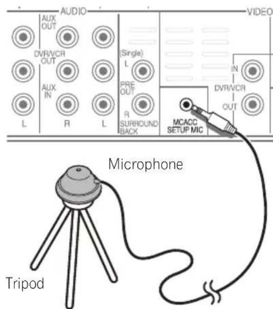
6 MCACC SETUP MIC jack
Use to connect the supplied microphone for the Auto MCACC setup (page 51).
7 Video inputs/outputs
Use the supplied video cable to connect the MONITOR OUT terminal to the television's video input terminal.
Use for connection to video sources, such as DVD players/recorders, VCRs, etc.
8 AC IN - Power inlet
9 SPEAKERS terminals
Match the colors of the speaker cables to their respective connectors.
Making cable connections
Make sure not to bend the cables over the top of this unit. If this happens, the magnetic field produced by the transformers in this unit may cause a humming noise from the speakers.

CAUTION
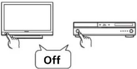
- When connecting this system or changing connections, be sure to switch power off and disconnect the power cord from the wall socket.
After completing all connections, connect the power cords to the wall socket.
About video outputs connection
This system is not loaded with a video converter. When you use HDMI cable for connecting to the input device, the same cables should be used for connecting to the TV.
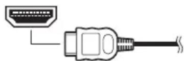
HDMI cables
The HDMI cables transfers uncompressed digital video, as well as almost every kind of digital audio that the connected component is compatible with, including DVD-video, DVD-Audio, Dolby Digital Plus, Dolby TrueHD, DTS-HD Master Audio (see below for limitations), Video CD/Super VCD, CD, SACD (DSD 2 ch only) and 192kHz / 8 ch (Max. number of channel inputs) PCM.
Be careful to connect the terminal in the proper direction.
About HDMI
HDMI (High Definition Multimedia Interface) supports both video and audio on a single digital connection for use with DVD players, DTV, set-top boxes, and other AV devices. HDMI was developed to provide the technologies of High Bandwidth Digital Content Protection (HDCP) as well as Digital Visual Interface (DVI) in one specification. HDCP is used to protect digital content transmitted and received by DVI-compliant displays.
HDMI has the capability to support standard, enhanced, or high-definition video plus standard to multi-channel surround-sound audio. HDMI features include uncompressed digital video, a bandwidth of up to 2.2 gigabytes per second (with HDTV signals), one connector (instead of several cables and connectors), and communication between the AV source and AV devices such as DTVs.
This system is also compatible with the DeepColor and x.v.Color feature (x.v.Color is trademarks of Sony Corporation).
HDMI, the HDMI Logo and High-Definition Multimedia Interface are trademarks or registered trademarks of HDMI Licensing, LLC in the United States and other countries.
Note
1 - Set the HDMI parameter in Setting the Audio options on page 69 to THRU (THROUGH) and set the input signal in Choosing the input signal on page 54 to HDMI, if you want to hear HDMI audio output from your TV (no sound will be heard from this system).
- If the video signal does not appear on your TV, try adjusting the resolution settings on your component or display. Note that some components (such as video game units) have resolutions that may not be displayed. In this case, use a (analog) composite connection.
The signals input from the (analog) composite video inputs of this unit will not be output from the HDMI OUT.
- When the video signal from the HDMI is 480i, 480p, 576i or 576p, Multi Ch PCM sound and HD sound cannot be received.

Important
- Compared to existing digital audio transmission formats (optical and coaxial), HDMI format digital audio transmissions requires a longer time to be recognized. Due to this, interruption in the audio may occur when switching between formats or beginning playback. Additionally, turning on/off the component connected to this unit's HDMI OUT terminal or disconnecting/connecting the HDMI cable may cause noise or interrupted audio.
Analog audio cables
Use stereo RCA phono cables to connect analog audio components. These cables are typically red and white, and you should connect the red plugs to R (right) terminals and white plugs to L (left) terminals.
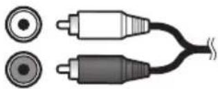
Digital audio cables
Commercially available coaxial digital audio cables or optical cables should be used to connect digital components to this system.
Coaxial digital audio cable


Optical cable


- A cap has been factory-attached to the connector on the accessory optical digital cable. Be sure to remove the cap before connecting the cable.

Standard RCA video cables
These cables are the most common type of video connection and are used to connect to the composite video terminals. The yellow plugs distinguish them from cables for audio.


Note
1 - When connecting optical cables, be careful when inserting the plug not to damage the shutter protecting the optical socket.
- When storing optical cable, coil loosely. The cable may be damaged if bent around sharp corners.
- You can also use a standard RCA video cable for coaxial digital connections.
Connect your TV (For TV audio)
This will allow you to play the sound from the TV's built-in tuner.
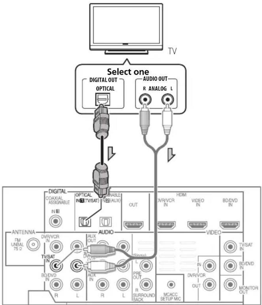
- Connect the digital audio output from your TV to the DIGITAL OPTICAL IN 1 (TV/ SAT) input on this system.
Use the supplied optical digital cable.
If your TV has no optical digital audio output, you can connect an analog audio outputs from your TV to the AUDIO TV/ SAT inputs on this system. Use an analog audio cables for the connection.
Connecting your TV and playback components
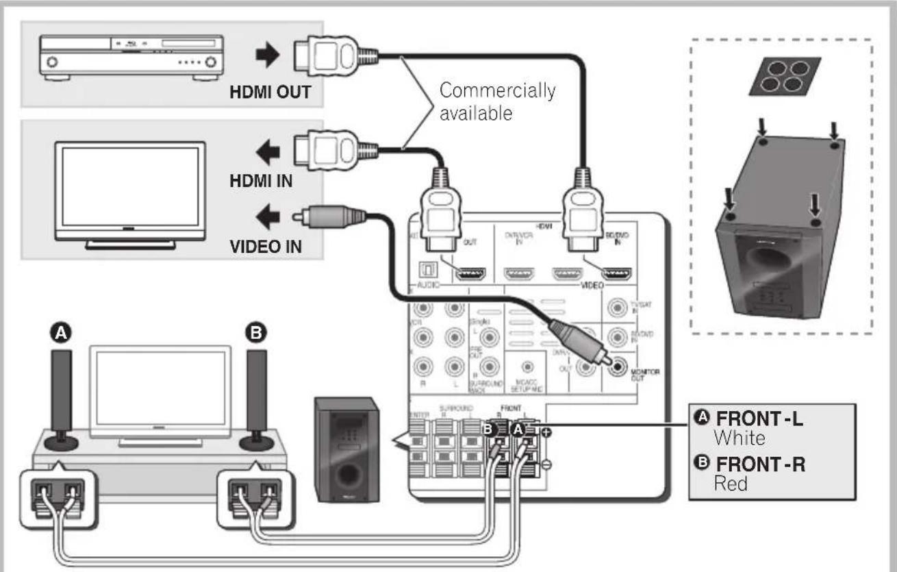
Connecting using HDMI
If you have an HDMI or DVI (with HDCP) equipped component (Blu-ray disc player, etc.), you can connect it to this system using a commercially available HDMI cable.
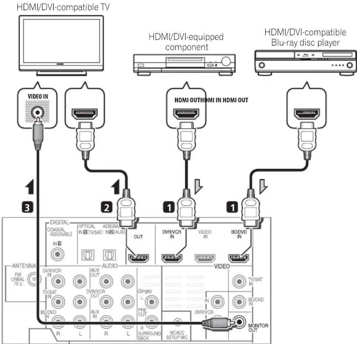
1 Connect the HDMI output on your BD/DVD player to the HDMI BD/DVD IN input on this system.
Use an HDMI cable for the connection.
2 Connect the HDMI OUT on this system to an HDMI input on your TV.
3 Connect the MONITOR OUT on this system to the composite video input on your TV.
The OSD will not appear if you have connected using the HDMI output to your TV. Use composite connections for system setup.
Use the supplied video cable.
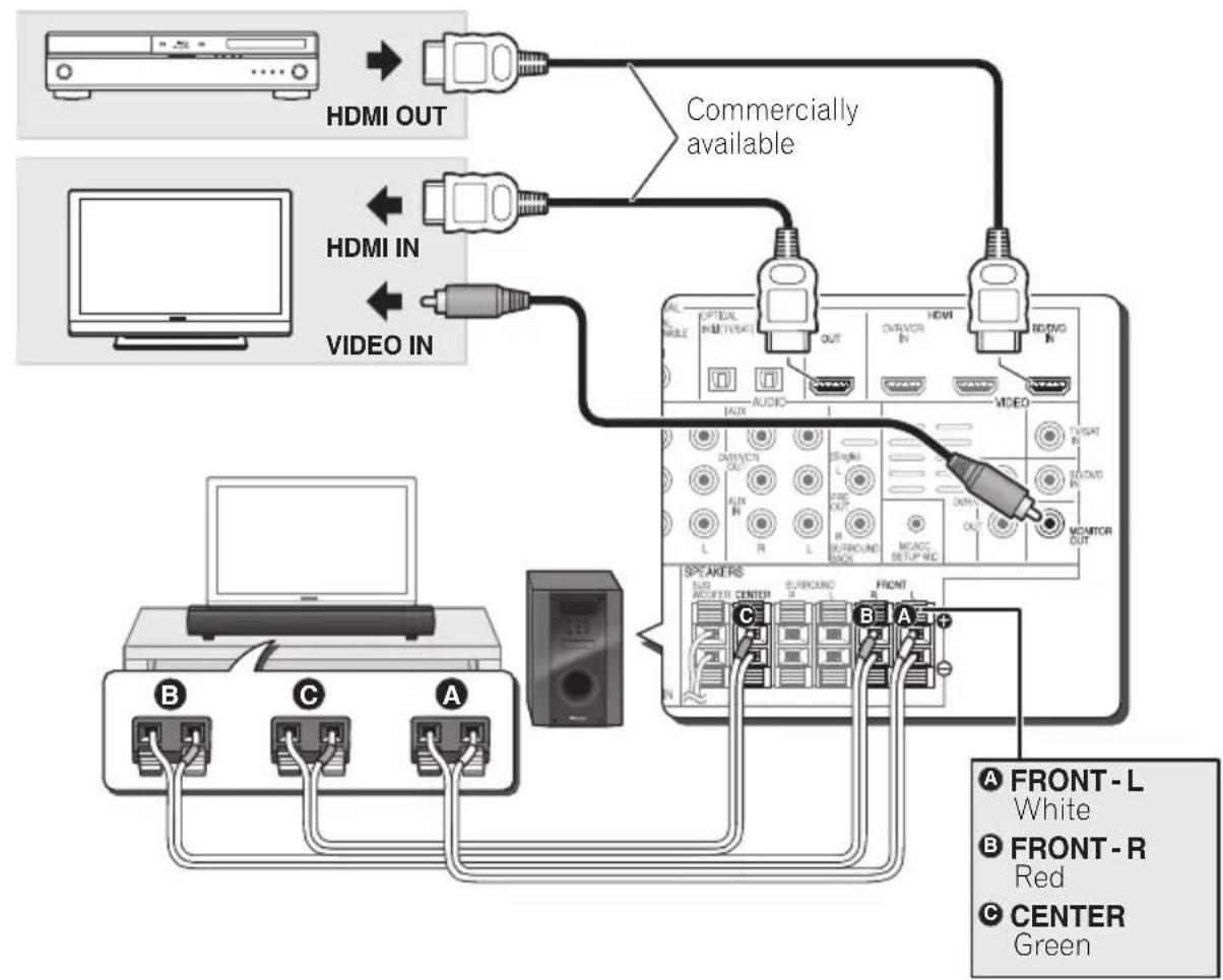
Connecting your component with no HDMI terminal
This diagram shows connections of a TV and DVD player (or other playback component) with no HDMI terminal to the system.
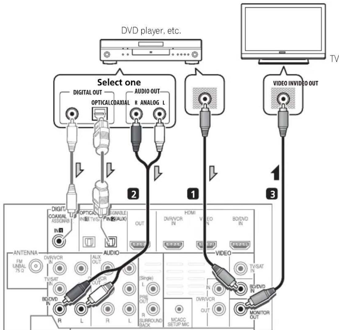
1 Connect the composite video output on your DVD player to the VIDEO BD/DVD input on this system.
Use a standard RCA video cable.
2 Connect the audio output on your DVD player to the AUDIO BD/DVD IN inputs on this system.
Use a stereo RCA phono cable. If your component has a digital output, you can also use an optical cable or coaxial cable for the connection.
3 Connect the MONITOR OUT on this system to the composite video input on your TV.
Use the supplied video cable.

Note
1 In this case, you'll need to tell the system which digital input you connected the component to (see Choosing the input signal on page 54).
Connecting an HDD/DVD recorder, VCR and other video sources
This system has audio/video inputs and outputs suitable for connecting analog or digital video recorders, including VCRs and HDD/DVD recorders.
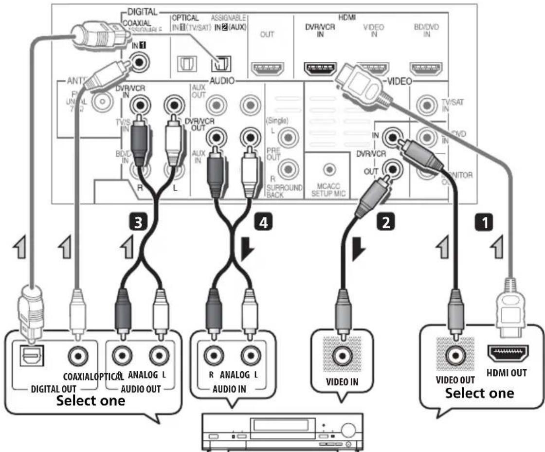
DVR, VCR, LD player, etc.
1 Connect the composite video output on your video component to the VIDEO DVR/VCR input on this system.
Use a standard RCA video cable.
- If the video component connected is equipped with an HDMI output, an HDMI cable may also be used for connection. In this case, use an HDMI cable to connect the TV as well.
2 Connect the VIDEO DVR/VCR OUT on this system to the composite video input on your video component.
3 Connect the audio output on your video component to the AUDIO DVR/VCR IN inputs on this system.
Use a stereo RCA phono cable. If your component has a digital output, you can also use an optical cable or coaxial cable for the connection.
4 Connect a video inputs on the recorder to the VIDEO DVR/VCR output on this system. Use a standard RCA video cable.

Note
1 In this case, you'll need to tell the system which digital input you connected the component to (see Choosing the input signal on page 54).
Connecting a satellite receiver or other digital set-top box
Satellite and cable receivers, and terrestrial digital TV tuners are all examples of so-called 'set-top boxes'.
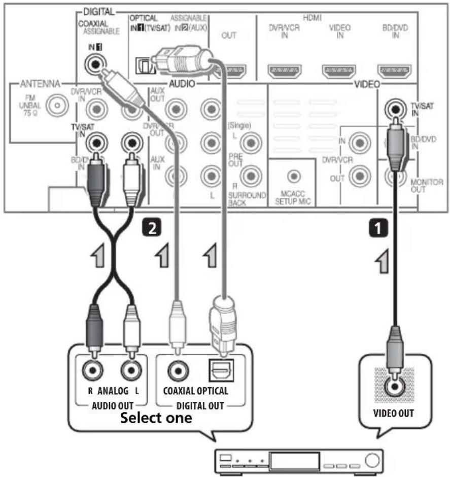
STB
1 Connect the composite video output on your set-top box to the VIDEO TV/SAT input on this system.
Use a standard RCA video cable.
2 Connect the audio output on your set-top box to the AUDIO TV/SAT IN inputs on this system.
Use a stereo RCA phono cable. If your component has a digital output, you can also use an optical cable or coaxial cable for the connection.

Note
1 In this case, you'll need to tell the system which digital input you connected the TV to (see Choosing the input signal on page 54).
Connecting other audio components
The number and kind of connections depends on the kind of component you're connecting. Follow the steps below to connect a CD-R, MD, DAT, tape recorder or other audio component.
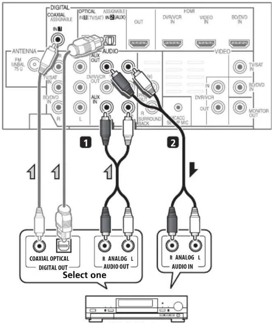
CD-R, MD, DAT, etc.
1 Connect the analog audio outputs of the component to a set of spare audio inputs on this system.
Use a stereo RCA phono cable. If your component has a digital output, connect this to a digital input on the system as shown.
2 If you're connecting a recorder, connect the analog audio outputs to the analog audio inputs on the recorder.
The example shows an analog connection to the AUX OUT analog output jack using a stereo RCA phono cable.

Note
1 Note that you must connect digital components to analog audio jacks if you want to record to/from digital components (like an MD) to/from analog components.
Connecting to the front panel video terminal
Front video connections are accessed via the front panel using the Video button on the remote control. There are standard audio/video jacks. Hook them up the same way you made the rear panel connections.
- Remove the panel cover when making connections to the front panel.
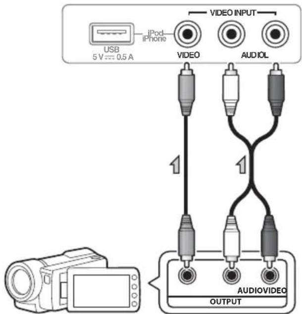
Video camera, etc.
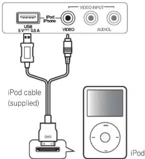
Connecting an iPod/iPhone
This system has a dedicated iPod/iPhone terminal that will allow you to control playback of audio content from your iPod/iPhone using the controls of this system.
-
Switch the system into standby then use the supplied iPod cable to connect your iPod to the iPod/iPhone terminal on the front panel of this system.
-
Remove the panel cover when making connections to the front panel.
- For the cable connection, refer to also the operating instructions for iPod.
- For instructions on playing the iPod, see Playing an iPod on page 55.

Note
1 If you connected the video components and there is still no sound, press SYSTEM then press SIGNAL SEL repeatedly to select A (ANALOG).
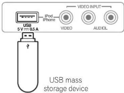
Connecting a USB device
It is possible to playback files using the USB interface on the front of this system.
-
Switch the system into standby then connect your USB device to the USB terminal on the front panel of this system.
-
Remove the panel cover when making connections to the front panel.
- For instructions on playing the USB device, see Playing a USB device on page 58.
Connecting the FM antenna
Connect the FM wire antenna as shown below. To improve reception and sound quality, connect external antennas (see Connecting external antennas below).
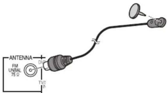
- Push the FM antenna plug onto the center pin of the FM antenna socket.
For best results, extend the FM antenna fully and fix to a wall or door frame. Don't drape loosely or leave coiled up.
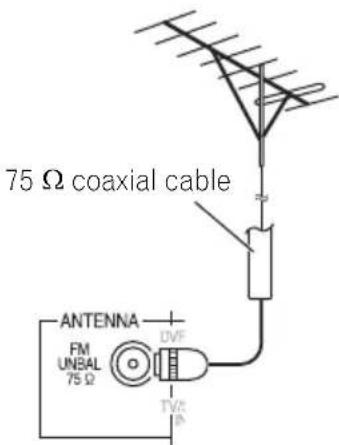
Connecting external antennas
To improve FM reception connect an external FM antenna to the FM UNBAL 75Ω.
Use the PRE OUT outputs to connect the surround back speakers
Connect the PRE OUT outputs of the system and additional amplifier to add a surround back speaker.
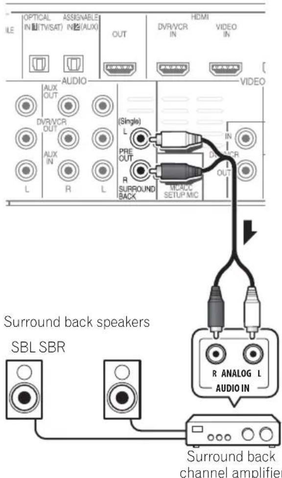
- You can use the additional amplifier on the surround back channel pre-outs for a single speaker as well. In this case plug the amplifier into the left (L (Single)) terminal only.
Plugging in the system
Only plug in after you have connected all your components to this system including the speakers.
1 Plug the supplied power cord into the AC IN socket on the back of the system.
2 Plug the other end into a power outlet.

CAUTION
- Handle the power cord by the plug part. Do not pull out the plug by tugging the cord, and never touch the power cord when your hands are wet, as this could cause a short circuit or electric shock. Do not place the unit, a piece of furniture, or other object on the power cord or pinch the cord in any other way. Never make a knot in the cord or tie it with other cables. The power cords should be routed so that they are not likely to be stepped on. A damaged power cord can cause a fire or give you an electric shock. Check the power cord once in a while. If you find it damaged, ask your nearest Pioneer authorized independent service company for a replacement.
- Do not use any power cord other than the one supplied with this unit.
- Do not use the supplied power cord for any purpose other than that described above.
- The system should be disconnected by removing the mains plug from the wall socket when not in regular use, e.g., when on vacation.
Chapter 3
Controls and displays
Front panel
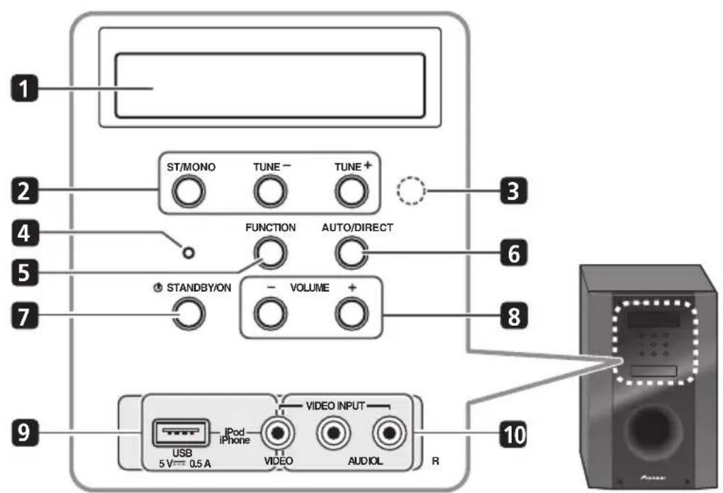
1 Front panel display
See Display on page 45 for details.
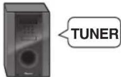
2 Tuner control buttons
ST/MONO
Switches between auto stereo mode and mono reception mode (page 60).
TUNE + / -
Used to find radio frequencies (page 60).
3 IR remote sensor
4 Power indicator
5 FUNCTION button
Selects an input source.
6 AUTO/DIRECT
Switches between Auto surround mode (Auto playback on page 63) and Stream Direct playback.
7 STANDBY/ON
Switches the system on or into standby.
8 VOLUME + / -
Adjusts the volume.
9 iPod/USB terminal
Use to connect your Apple iPod or USB mass storage device as an audio source (page 55 and 58).
10 AUDIO/VIDEO input
See Connecting to the front panel video terminal on page 41.
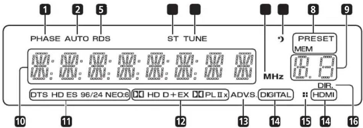
Display
1 P H A S E
Lights when the Phase Control is switched on (page 66).
2 A U T O
Lights when the Auto Surround feature is switched on (see Auto playback on page 63).
3 RDS
Lights when an RDS broadcast is received (page 62).
4ST
Lights when a stereo FM broadcast is being received in auto stereo mode.
5 T U N E
Lights when a normal broadcast channel is being received.
6 MHz
Lights when the character display is showing the currently received broadcast frequency.
7 Sleep timer indicator
Lights when the system is in sleep mode (page 49).
8 Tuner preset indicators
PRESET
Shows when a preset radio station is registered or called.
MEM
Blinks when a radio station is registered.
9 PRESET Information or Input signal indicator
Shows the preset number of the tuner or the input signal type, etc.
10 Character display
Displays various system information.
11 DTS indicators
DTS
Lights when a source with DTS encoded audio signals is detected.
HD
Lights when a source with DTS-EXPRESS or DTS-HD encoded audio signals is detected.
ES
Lights when a source with DTS-ES encoded audio signals is detected.
96/24
Lights when a source with DTS 96/24 encoded audio signals is detected.
NEO:6
When one of the NEO:6 modes of the system is on, this lights to indicate NEO:6 processing (page 63).
Controls and displays
12 Dolby Digital indicators
D D
Lights when a Dolby Digital encoded signal is detected.
D+
Lights when a source with Dolby Digital Plus encoded audio signals is detected.
DDHD
Lights when a source with Dolby TrueHD encoded audio signals is detected.
EX
Lights when a source with Dolby Digital EX encoded audio signals is detected.
PLII(x)
Lights to indicate Pro Logic II/ Pro Logic IIx decoding (see Listening in surround sound on page 63 for more on this).
13 ADV.S.
Lights when one of the Advanced Surround modes has been selected (see Using the Advanced surround effects on page 64 for more on this).
14 SIGNAL SELECT indicators
DIGITAL
Lights when a digital audio signal is selected.
Blinks when a digital audio signal is not selected.
HDMI
Lights when an HDMI signal is selected. Blinks when an HDMI signal is selected and selected HDMI input is not provided.
15 UP MIX indicator
Lights when the UP MIX function is set to ON (page 68). Also, lights when DIMMER is set to off.
16 DIR.
Lights when the DIRECT or PURE DIRECT mode is switched on (page 65).
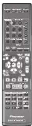
Remote control
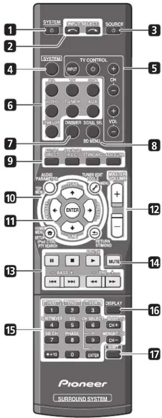
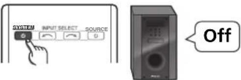
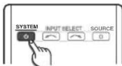
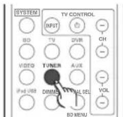
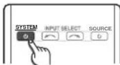
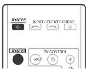
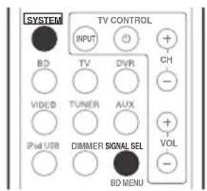
1 SYSTEM
Switches the system between standby and on.
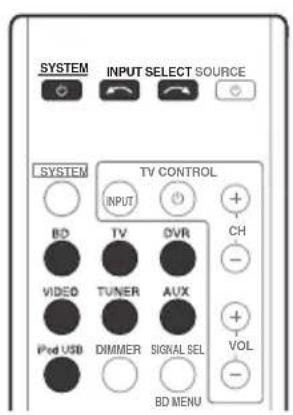
2 INPUT SELECT
Use to select the input source.
3 SOURCE
Press to turn on/off other components connected to the system (see page 77 for more on this).
4 SYSTEM
Switches the remote to control the system (used to select the white commands above the number buttons (S.RETRIEVER, etc)). Also use this button to set up surround sound (page 72) or Audio parameters (page 65).
5 TV CONTROL buttons
These buttons are dedicated to control the TV assigned to the TV button. Thus if you only have one TV to hook up to this system assign it to the TV button (see page 76 for more on this).
Use to turn on/off the power of the TV.
INPUT
Use to select the TV input signal.
CH + / -
Use to select channels.
VOL + / -
Use to adjust the volume on your TV.
6 MULTI CONTROL buttons
Press to select control of other components (see Controlling the rest of your system on page 75).
7 DIMMER
Dims or brightens the display. The brightness can be controlled in four steps.
8 SIGNAL SEL
Use to select an input signal (page 54).
Press BD first to access:
BD MENU
Displays the disc menu of Blu-ray Discs.
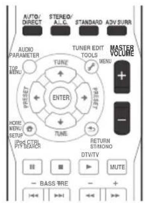
9 Listening mode buttons
AUTO/DIRECT
Switches between Auto surround mode (Auto playback on page 63) and Stream Direct playback. Stream Direct playback bypasses the tone controls for the most accurate reproduction of a source (page 65).
STEREO/A.L.C.
Switches between stereo playback, Auto level control stereo mode (page 64) and Front Stage Surround Advance modes (page 65).
STANDARD
Press for Standard decoding and to switch between Pro Logic II options (page 63).
ADV SURR
Switches between the various surround modes (page 64).
10 System Setup and Component control buttons
The following button controls can be accessed after you have selected the corresponding
MULTI CONTROL button (BD, TV, etc.).
Press SYSTEMAccess:
AUDIO PARAMETER
Use to access the Audio options (page 65).
SETUP
Press to access the System Setup menu (page 72).
RETURN
Confirm and exit the current menu screen. Press BD or DVR first to access:
TOP MENU
Displays the disc 'top' menu of a BD/DVD.
HOME MENU
Displays the HOME MENU screen.
RETURN
Confirm and exit the current menu screen.
MENU
Displays the TOOLS menu screen of Blu-ray Disc player.
Press TUNER first to access:
TUNER EDIT
Memorizes/names stations for recall (page 60 and 61).
ST/MONO
Switches between auto stereo mode and mono reception mode (page 60).
PTY SEARCH
Use to search for RDS program types (page 62).
Press iPod USB first to access:
iPod CTRL
Switches between the iPod controls and the system controls (page 57).
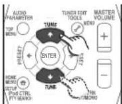
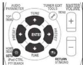
11 (TUNE / , PRESET / ), ENTER
Use the arrow buttons when setting up your surround sound system (page 72). Also used to control BD/DVD menus/options.
Use the TUNE / buttons can be used to find radio frequencies (page 60) and the
P r e s e t / buttons can be used to select preset radio stations (page 61).
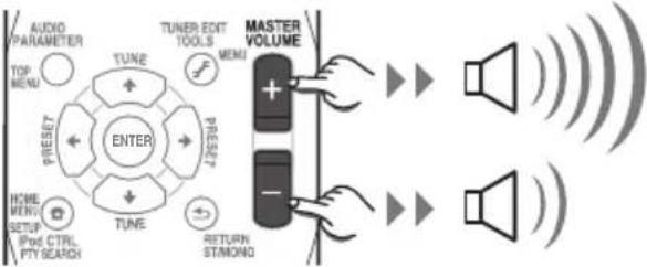
12 MASTER VOLUME + / -
Use to set the listening volume.
13 Component control buttons
The main buttons ( , , etc.) are used to control a component after you have selected it using the input source buttons.
The controls above these buttons can be accessed after you have selected the corresponding input source button (for example BD, DVR or TV). These buttons also function as described below.
Press SYSTEMaccess:
BASS-/+
Use to adjust the channel level of the subwoofer.
TRE -/+
Use to adjust Treble
Press TV first to access:
DTV/TV
Switches between the DTV and analog TV input modes for Pioneer TVs.
14 MUTE
Mutes/unmutes the sound.
15 Number buttons and other component controls
Use the number buttons to directly select a radio frequency (page 60) or the tracks on a CD, DVD, etc. There are other buttons that can be accessed after the system pressed. (For example MIDNIGHT, etc.)
HDD*, DVD*, VCR*
These buttons switch between the hard disk, DVD and VCR controls for HDD/DVD/ VCR recorders.
S.RETRIEVER
Press to restore CD quality sound to compressed audio sources (page 65).
EQ
Press to switch on/off Acoustic Calibration EQ setting (page 66).
CH SELECT
Press repeatedly to select a channel, then use + / - to adjust the level (page 74).
CH SELECT +/-
Use to adjust the channel level.
SBCH
Use to select the surround back channel mode (page 68).
PHASE
Press to switch on/off Phase Control (page 66).
MIDNIGHT
Press to switch on/off Midnight listening (page 69).
SLEEP
Press to change the amount of time before the system switches into standby (30 min - 60 min - 90 min - Off). You can check the remaining sleep time at any time by pressing SLEEP once.
16 DISPLAY
Switches the display of this unit. The input name, listening mode or sound volume can be checked by selecting an input source.
17 SHIFT
Press to access the 'boxed' commands (above the buttons) on the remote. These buttons are marked with an asterisk (*) in this section.

Note
1 The tone controls are disabled when the listening mode is set to DIRECT or PURE DIRECT.
Putting the batteries in the remote control
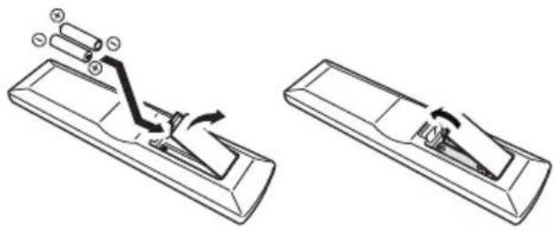

CAUTION
Incorrect use of batteries can result in hazards such as leakage and bursting. Please observe the following:
- Don't mix new and old batteries together.
- Don't use different kinds of battery together - although they may look similar, different batteries may have different voltages.
- Make sure that the plus and minus ends of each battery match the indications in the battery compartment.
- Remove batteries from equipment that isn't going to be used for a month or more.
- When disposing of used batteries, please comply with governmental regulations or environmental public instruction's rules that apply in your country/area.
- Do not use or store batteries in direct sunlight or other excessively hot place, such as inside a car or near a heater. This can cause batteries to leak, overheat, explode or catch fire. It can also reduce the life or performance of batteries.
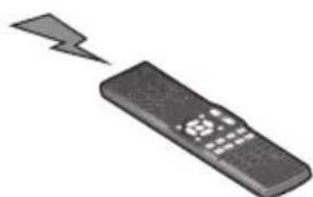
Using the remote control
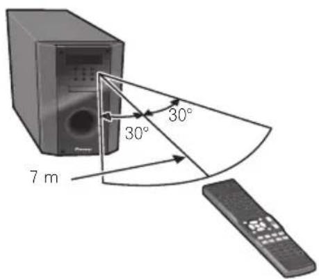
Please keep in mind the following when using the remote control:
Make sure that there are no obstacles between the remote and the remote sensor on the unit.
- Remote operation may become unreliable if strong sunlight or fluorescent light is shining on the unit's remote sensor.
- Remote controllers for different devices can interfere with each other. Avoid using remotes for other equipment located close to this unit.
- Replace the batteries when you notice a fall off in the operating range of the remote.
- Use within the operating range in front of the remote control sensor on the unit, as shown.
Chapter 4 Getting started
Automatically setting up for surround sound (MCACC)
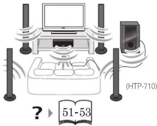
The Auto Multi-Channel Acoustic Calibration (MCACC) setup measures the acoustic characteristics of your listening area, taking into account ambient noise, speaker size and distance, and tests for both channel delay and channel level. After you have set up the microphone provided with your system, the system uses the information from a series of test tones to optimize the speaker settings and equalization for your particular room.

CAUTION
- The test tones used in the Auto MCACC Setup are output at high volume.

Important
- When using HTP-FS510 and HTP-SB510 models, always use the Auto MCACC setup function. If this setup is not performed, various problems may occur, including an inability to hear screen dialogue, or to hear sound from the surround channel. In the event the Auto MCACC setup is not used, perform the manual Speaker Setting instead.
-
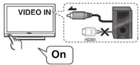
The OSD will not appear if you have connected using the HDMI output to your TV. Use composite connections for system setup.
The Auto MCACC Setup will overwrite any existing speaker settings you've made. -
Before using the Auto MCACC Setup, the iPod USB function should not be selected as an input source.
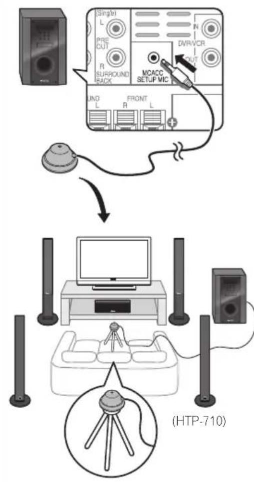
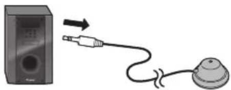
1 Connect the microphone to the MCACC SETUP MIC jack on the rear panel.
Make sure there are no obstacles between the speakers and the microphone.
If you have a tripod, use it to place the microphone so that it's about ear level at your normal listening position. Otherwise, place the microphone at ear level using a table or a chair.
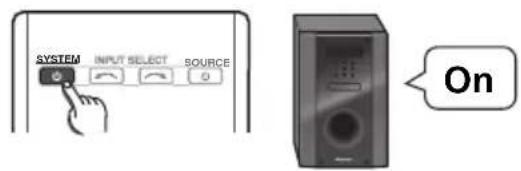
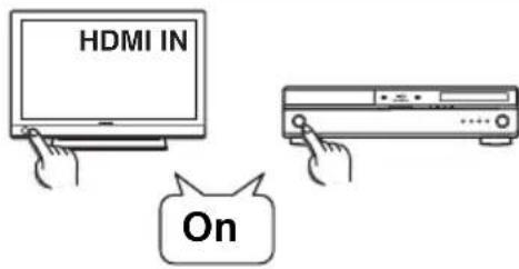
2 Switch on the system and your TV.
Switch the TV input so that it connects to the system in analog.
Getting started
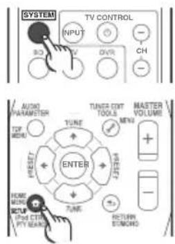
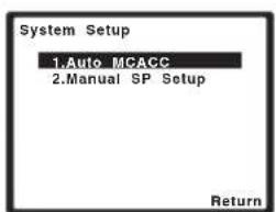
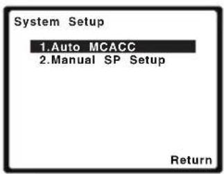
3 Press the Note control, then press the SETUP button.
An on-screen display (OSD) appears on your TV. Use ↑/↓/←/→ and ENTER on the remote control to navigate through the screens and select menu items. Press RETURN to exit the current menu.
- Press SETUP at any time to exit the System Setup menu.
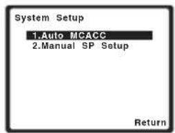
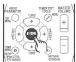
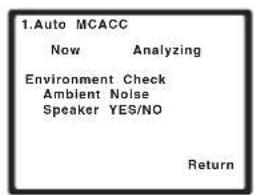
4 Select 'Auto MCACC' from the System Setup menu then press ENTER.2
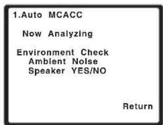
Try to be as quiet as possible after pressing ENTER. The system outputs a series of test tones to establish the ambient noise level.
5 Follow the instructions on-screen.
- Make sure the microphone is connected.
See below for notes regarding background noise and other possible interference. - When using surround back speakers, turn on the power to the amplifier to which the surround back speakers are connected, and adjust the sound level to the desired level.
6 Wait for the test tones to finish.
- A progress report is displayed on-screen while the system outputs test tones to determine the speakers present in your setup. Try to be as quiet as possible while it's doing this.
- For correct speaker settings, do not adjust the volume during the test tones.
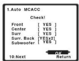
7 Confirm the speaker configuration.
The configuration shown on-screen should reflect the actual speakers you have.
- With error messages (such as Too much ambient noise) select RETRY after checking for ambient noise (see Other problems when using the Auto MCACC Setup on page 53).
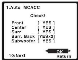
If the speaker configuration displayed isn't correct, use / to select the speaker and / to change the setting. When you're finished, go to the next step.
If you see an error message (ERR) in the right side column, there may be a problem with the speaker connection. If selecting RETRY doesn't fix the problem, turn off the power and check the speaker connections.

Note
The screenshot automatically starts after three minutes of inactivity. If you cancel the Auto MCACC Setup at any time, the system automatically exits and no settings will be made.
2 MIC IN blinks when the microphone is not connected to MCACC SETUP MIC.
8 Make sure 'OK' is selected, then press ENTER.
If the screen in step 7 is left untouched for 10 seconds and the ENTER button is not pressed in step 8, the Auto MCACC setup will start automatically as shown below.
A progress report is displayed on-screen while the system outputs more test tones to determine the optimum system settings for channel level, speaker distance, and Acoustic Calibration EQ.
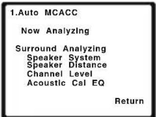
Again, try to be as quiet as possible while this is happening. It may take 1 to 3 minutes.
9 The Auto MCACC Setup has finished! You return to the System Setup menu.
- Be sure to disconnect the microphone from this unit upon completion of the Auto MCACC setup.
The settings made in the Auto MCACC Setup should give you excellent surround sound from your system, but it is also possible to adjust these settings manually using the System Setup menu (starting on page 72).
Other problems when using the Auto MCACC Setup
If the room environment is not optimal for the Auto MCACC Setup (too much background noise, echo off the walls, obstacles blocking the speakers from the microphone) the final settings may be incorrect. Check for household appliances (air conditioner, fridge, fan, etc.), that may be affecting the environment and switch them off if necessary. If there are any instructions showing in the front panel display, please follow them.
Some older TVs may interfere with the operation of the microphone. If this seems to be happening, switch off the TV when doing the Auto MCACC Setup.

Note
1 The subwoofer distance setting may be farther than the actual distance from the listening position. This setting should be accurate (taking delay and room characteristics into account) and generally does not need to be changed.
Getting started
Basic operation
Procedures for listening to audio from a radio or connected other component.
1 Turn on the power of the playback component.
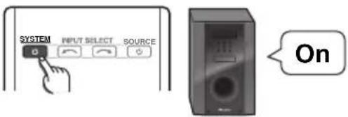
2 P r cSytEM to turn on the power of this system.
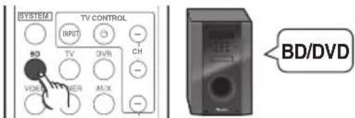
3 Select the source you want to playback. Use the MULTI CONTROL (or INPUT SELECTOR) buttons.
- Select the type of audio input signal if required (see below).
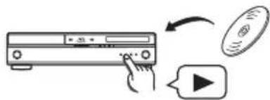
4 Start playback of the component you selected in step 1.
5 Select the listening mode.
Use the listening mode buttons.
6 P r MaSsERsVOLUME + / - to adjust the volume.
Choosing the input signal
On this system, it is possible to switch the input signals for the different inputs as described below.
1 Press dyheHote control.
2 Press SIGNAL SEL to select the input signal corresponding to the source component.
When DIGITAL (C1/O1/O2) or HDMI (H) is selected and the selected audio input is not provided, A (analog) is automatically selected. Each press cycles through the following:
- A - Selects the analog inputs.
- DIGITAL - Selects the digital input. The coaxial 1 input is selected for C1, and the optical 1 or 2 audio input is selected for O1 or O2.
- HDMI - Selects an HDMI signal. H can be selected for BD/DVD,VIDEO or DVR/VCR input. For other inputs, HDMI cannot be selected.2
When set to DIGITAL or HDMI, lights when a Dolby Digital signal is input, and DTS lights when a DTS signal is input.
When the HDMI is selected, the A and DIGITAL indicators are off (see page 44).
Note
1 This system can only play back Dolby Digital, PCM (32 kHz to 96 kHz) and DTS (including DTS 96 kHz / 24 bit) digital signal formats. The compatible signals via the HDMI terminals are: Dolby Digital, DTS, SACD (DSD 2 ch), PCM (32 kHz to 192 kHz sampling frequencies), Dolby TrueHD, Dolby Digital Plus, DTS-EXPRESS, DTS-HD Master Audio and DVD Audio (including 192 kHz). With other digital signal formats, set to A (analog).
- You may get digital noise when a LD or CD player compatible with DTS is playing an analog signal. To prevent noise, make the proper digital connections (page 33) and set the signal input to C1/O1/O2 (DIGITAL).
Some DVD players don't output DTS signals. For more details, refer to the instruction manual supplied with your DVD player.
2 When the HDMI option in Setting the Audio options on page 69 is set to THRU, the sound will be heard through your TV, not from this system.
Chapter 5 iPod/USB playback
Playing an iPod
This system has a dedicated iPod terminal that will allow you to control playback of audio content from your iPod using the controls of this system.

Important
- When connected to a television using HDMI output alone, the iPod Top menu will not be displayed. In this case, use composite connection instead.
1 Switch on the system and your TV.
See Connecting an iPod/iPhone on page 41.
2 Press the iPod USB button to switch the system to the iPod/USB.
The front panel display shows Loading while the system verifies the connection and retrieves data from the iPod.
3 U s @TOptMENu button to display iPod Top menu.
When the display shows Top Menu you're ready to play music from the iPod.2
If after pressing iPod the display shows NO DEVICE, try switching off the system and reconnecting the iPod to the system.
iPod playback
To navigate songs on your iPod, you can take advantage of the OSD of your TV connected to this system.3 You can also control all operations for music in the front panel display of this system.
Finding what you want to play
When your iPod is connected to this system, you can browse songs stored on your iPod by playlist, artist, album name, song name, genre or composer, similar to using your iPod directly.
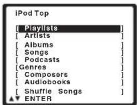
1 U s /b buttons to select a category then press ENTER to browse that category.
To return to the previous level any time, press RETURN.
Note
1 This system is compatible with the audio and the video of the iPod nano, iPod fifth generation, iPod classic, iPod touch and iPhone (iPod shuffle not supported). However, that some of the functions may be restricted for some models. Note, however, compatibility may vary depending on the software version of your iPod and iPhone. Please be sure to use the latest available software version.
- iPod and iPhone are licensed for reproduction of non-copyrighted materials or materials the user is legally permitted to reproduce.
- Features such as the equalizer cannot be controlled using this system, and we recommend switching the equalizer off before connecting.
- Pioneer cannot under any circumstances accept responsibility for any direct or indirect loss arising from any inconvenience or loss of recorded material resulting from the iPod failure.
2 The controls of your iPod (excluding iPod touch or iPhone) will be inoperable when connected to this system (Pioneer shows in the iPod display).
3 - Note that non-roman characters in the title are displayed as *
This feature is not available for photos or video clips on your iPod.
2 U s e/bltoes to browse the selected category (e.g., albums).
Use / to move to previous/next levels.
3 Continue browsing until you arrive at what you want to play, then press to start playback.1
Navigation through categories on your iPod looks like this:
Playlists Songs
Artists Albums Songs
Albums Songs
Songs
Podcasts
Genres Artists Albums Songs
Composers Albums Songs
Audiobooks
Shuffle Songs

Tip
- You can play all of the songs in a particular category by selecting the All item at the top of each category list. For example, you can play all the songs by a particular artist.
Basic playback controls
The following table shows the basic playback controls for your iPod. Press iPod USB to switch the remote control to the iPod operation mode.
Button What it does
Press to start playback.
If you start playback when
something other than a song is
selected, all the songs that fall into
that category will play.
ENTER Press to set the play and pause modes.
1
Pauses playback, or restarts
playback when paused.

Press and hold during playback to
start scanning.
Press to skip to previous/next track.

Press repeatedly to switch between
Repeat One, Repeat All and
Repeat Off.

Press repeatedly to switch between
Shuffle Songs. Shuffle Albums
and Shuffle Off.
DISPLA
Press repeatedly to change the song
playback information displayed in
the front panel display.

When browsing, press to move to
previous/next levels.

During Audiobook playback, press
to switch the playback speed: Faster
Normal Slower
TOP
Press to return to the iPod Top
MENU
menu screen.
RETURN
Press to return to the previous level.

Note
1 If you're in the song category, you can also press ENTER to start playback.
Watching photos and video content
To view photos or video on your iPod, since video control is not possible using this system, you must use the main controls of your iPod instead.

Important
- To play photos or video on your iPod, you must connect the composite MONITOR OUT jack and TV. The photos and video content will not appear if you have connected using the HDMI output to your TV.
1 Press iPod CTRL to switch to the iPod controls for photo and video playback.
The system controls will be unavailable while you are watching iPod videos or browsing photos.
2 Press iPod CTRL again to switch back to the system controls when you're done.
About iPod/iPhone
Made for

iPod iPhone
"Made for iPod" and "Made for iPhone" mean that an electronic accessory has been designed to connect specifically to iPod, or iPhone, respectively, and has been certified by the developer to meet Apple performance standards. Apple is not responsible for the operation of this device or its compliance with safety and regulatory standards.
iPod and iPhone are a trademarks of Apple Inc., registered in the U.S. and other countries.

Note
1 iPod photos and video content can be viewed only when the iPod is connected to the iPod Video input on the front panel.
- This feature can only be used with an iPod having video output.
Playing a USB device
It is possible to listen to two-channel audio using the USB interface on the front of this system.

Important
- When connected to a television using HDMI output alone, the USB playback window of the on-screen display (OSD) will not be displayed. In this case, use composite connection instead.
1 Switch on the system and your TV.
2 P r iPod USB on the remote control to switch the system to the iPod/USB.
No Device appears in the OSD.
3 Connect your USB device. 2
See Connecting a USB device on page 42.
Loading appears in the OSD as this system starts recognizing the USB device connected. After the recognition, a playback screen appears in the OSD and playback starts automatically.
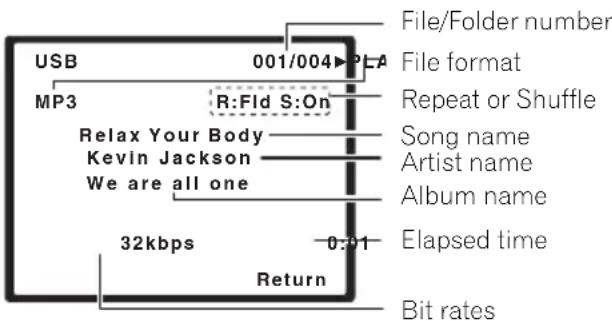
Basic playback controls
The following table shows the basic controls on the remote for USB playback. Press iPod USB to switch the remote control to the iPod USB operation mode.
Button What it does
Starts normal playback.
Pauses/unpauses playback.
Press to skip to previous/next track.
Press and hold during playback to start scanning.
Press repeatedly to switch between Repeat Folder, Repeat One and Repeat All.
Press repeatedly to switch between Shuffle On and Shuffle Off.
DISPLAY Press repeatedly to change the song playback information displayed in the front panel display.
/ During playback, press to skip to ↑/↓ previous/next track.
TOP Press to return to the menu screen.
MENU
RETURN Press to return to the previous level.
Note
This includes playback of WMA/MP3/MPEG-4 AAC files (except files with copy-protection or restricted playback).
2 - Make sure the system is in standby when disconnecting the USB device.
- Compatible USB devices include external magnetic hard drives, portable flash memory (particularly keydrives) and digital audio players (MP3 players) of format FAT16/32. It is not possible to connect this system to a personal computer for USB playback.
- Pioneer cannot guarantee compatibility (operation and/or bus power) with all USB mass storage devices and assumes no responsibility for any loss of data that may occur when connected to this system.
- With large amounts of data, it may take longer for the system to read the contents of a USB device.
3 - If the file selected cannot be played back, this system automatically skips to the next file playable.
- When the file currently being played back has no title assigned to it, the file name is displayed in the OSD instead; when neither the album name nor the artist name is present, the row is displayed as a blank space.
- Note that non-roman characters in the playlist are displayed as *

Important
If a USB Error message lights in the display, try following the points below:
- Switch the system off, then on again.
- Reconnect the USB device with the system switched off.
- Select another input source (like BD), then switch back to iPod USB.
- Use a dedicated AC adapter (supplied with the device) for USB power.
For more information on error messages, see USB messages on page 88.
If this doesn't remedy the problem, it is likely your USB device is incompatible.
Compressed audio compatibility
Note that although most standard bit/ sampling rate combinations for compressed audio are compatible, some irregularly encoded files may not play back. The list below shows compatible formats for compressed audio files:
- MP3 (MPEG-1/2/2.5 Audio Layer 3) - Sampling rates: 8kHz to 48kHz ; Bit rates: 8 kbps to 320 kbps (128 kbps or higher recommended); File extension:.mp3
WMA (Windows Media Audio) - Sampling rates: 32 kHz / 44.1 kHz; Bit rates: 32 kbps to 192 kbps (128 kbps or higher recommended); File extension: .wma; WMA9 Pro and WMA lossless encoding: No - AAC (MPEG-4 Advanced Audio Coding) - Sampling rates: 11.025 kHz to 48 kHz; Bit rates: 16 kbps to 320 kbps (128 kbps or higher recommended); File extension:.m4a; Apple lossless encoding: No
Other compatibility information
VBR (variable bit rate) MP3/WMA/MPEG-4 AAC playback: Yes
- DRM (Digital Rights Management) protection compatible: Yes (DRM-protected audio files will not play in this system).
About MPEG-4 AAC
Advanced Audio Coding (AAC) is at the core of the MPEG-4 AAC standard, which incorporates MPEG-2 AAC, forming the basis of the MPEG-4 audio compression technology. The file format and extension used depend on the application used to encode the AAC file. This system plays back AAC files encoded by iTunes bearing the extension '.m4a'. DRM-protected files will not play, and files encoded with some versions of iTunes may not play.
Apple and iTunes are trademarks of Apple Inc., registered in the U.S. and other countries.
About WMA

The Windows Media logo printed on the box indicates that this system can playback Windows Media Audio content.
WMA is an acronym for Windows Media Audio and refers to an audio compression technology developed by Microsoft Corporation. This system plays back WMA files encoded using Windows Media Player bearing the extension .wma'. Note that DRM-protected files will not play, and files encoded with some versions of Windows Media Player may not play.
Windows Media, and the Windows logo are trademarks or registered trademarks of Microsoft Corporation in the United States and/or other countries.
Chapter 6
Using the tuner
Listening to the radio
The following steps show you how to tune in to FM broadcasts using the automatic (search) and manual (step) tuning functions. Once you are tuned to a station you can memorize the frequency for recall later—see Saving station presets below for more on how to do this.
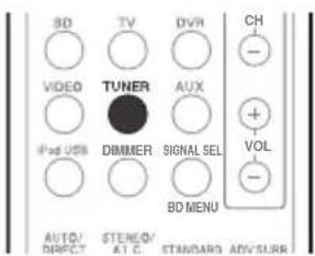
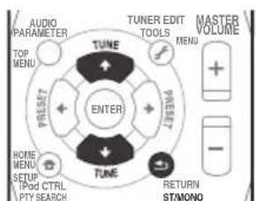
1 P r TUNER to select the tuner.
2 Tune to a station.
There are three ways to do this:
Automatic tuning
To search for stations in the currently selected band, press and hold TUNE / (remote control or front panel) for about a second. The system will start searching for the next station, stopping when it has found one. Repeat to search for other stations.
Manual tuning
To change the frequency one step at a time, press TUNE ↑/↓.
High speed tuning
Press and hold TUNE / for high speed tuning. Release the button at the frequency you want.
Improving FM stereo sound
If the TUNE or ST indicators don't light when tuning to an FM station because the signal is weak, press the ST/MONO button to select FM MONO and set the system to the mono reception mode. This should improve the sound quality and allow you to enjoy the broadcast.
Saving station presets
If you often listen to a particular radio station, it's convenient to have the system store the frequency for easy recall whenever you want to listen to that station. This saves the effort of manually tuning in each time. This unit can memorize up to 30 stations.
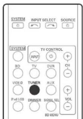
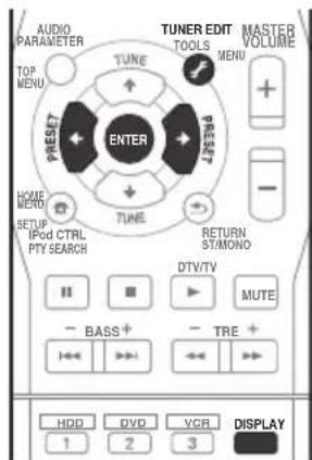
1 Tune to a station you want to memorize.
See Listening to the radio above for more on this.
2 Press TUNER EDIT.
The display shows PRESET, then a blinking MEM and station preset.

Note
If the system is left disconnected from the AC power outlet for over a month, the station memories will be lost and will have to be reprogrammed.
3 Press PRESET / to select the station preset you want.
You can also use the number buttons.
4 Press ENTER.
After pressing ENTER, the preset number stop blinking and the system stores the station.
Listening to station presets
You will need to have some presets stored to do this. See Saving station presets on page 60 if you haven't done this already.
-
Press PRESET / to select the station preset you want.
-
You can also use the number buttons on the remote control to recall the station preset.
Naming preset stations
For easier identification, you can name all of your preset stations.
1 Choose the station preset you want to name.
See Listening to station presets above for how to do this.
2 Press TUNER EDIT twice.
The cursor at the first character position is blinking on the display.
3 Input the name you want.
Choose a name up to eight characters long.
- Use the PRESET / buttons to select character position.
- Use the TUNE ↑/↓ buttons to select characters.
- The name is stored when ENTER is pressed.

Tip
To erase a station name, follow steps 1 and 2, and press ENTER while the display is blank. Press TUNER EDIT while the display is blank, to keep the previous name.
- Once you have named a station preset, press DISPLAY to show the name. When you want to return to the frequency display, press DISPLAY several times to show the frequency.
An introduction to RDS
Radio Data System (RDS) is a system used by most FM radio stations to provide listeners with various kinds of information—the name of the station and the kind of show they're broadcasting, for example.
One feature of RDS is that you can search by type of program. For example, you can search for a station that's broadcasting a show with the program type, JAZZ.
You can search the following program types:
NEWS - News
AFFAIRS - Current Affairs
INFO - General Information
SPORT-Sport
EDUCATE - Educational
DRAMA - Radio plays, etc.
CULTURE - National or regional culture, theater, etc.
SCIENCE - Science and technology
VARIED - Usually talk-based material, such as quiz shows or interviews.
POP M - Pop music
ROCK M - Rock music
EASY M - Easy listening
LIGHT M - 'Light' classical music
CLASSICS - 'Serious' classical music
OTHER M - Music not fitting above categories
WEATHER - Weather reports
FINANCE - Stock market reports, commerce, trading, etc.
CHILDREN - Programs for children
SOCIAL - Social affairs
RELIGION - Programs concerning religion
PHONE IN - Public expressing their views by phone
TRAVEL-Holiday-type travel rather than traffic announcements
LEISURE-Leisure interests and hobbies
JAZZ-Jazz
COUNTRY - Country music
NATION M - Popular music in a language other than English
OLDIES - Popular music from the '50s and '60s
FOLK M - Folk music
DOCUMENT
Documentary

Note
1 In addition, there are three other program types, ALARMTST, ALARM, and NO TYPE. ALARM and ALARMTST are used for emergency announcements. NO TYPE appears when a program type cannot be found.
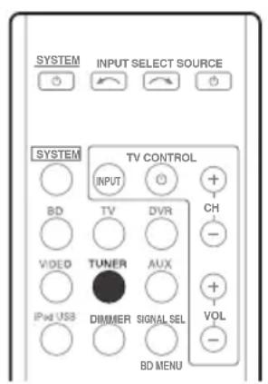
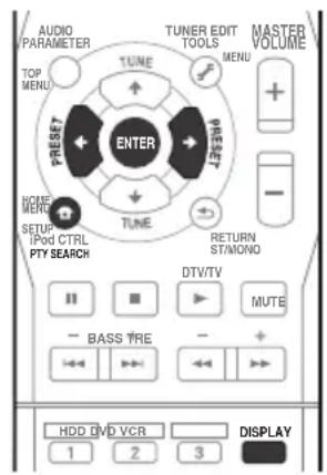
Searching for RDS programs
You can search for a program type listed above.
1 P r TUNER. s
2 P r PEY SEARCH.
SEARCH shows in the display.
3 P r PREsT / to select the program type you want to hear.
4 P r ENTER to search for the program type.
The system starts searching through the station presets for a match, stopping when it was found one. Repeat to search for other stations.
If NO PTY is displayed it means the tuner couldn't find that program type at the time of the search.
Displaying RDS information
Use the DISPLAY button to display the different types of RDS information available.2
- Press DISPLAY for RDS information.
Each press changes the display as follows:
- Listening mode
- Master volume
- Radio Text (RT) - Messages sent by the radio station. For example, a talk radio station may provide a phone number as RT.
- Program Service Name (PS) - The name of the radio station.
- Program Type (PTY) - This indicates the kind of program currently being broadcast.
- Current tuner frequency (FREQ)

Note
1 RDS searches station presets only. If no stations have been preset, or if the program type could not be found among the station presets NO PTY is displayed. FINISH means the search is complete.
2 - If any noise is picked up while displaying the RT scroll, some characters may be displayed incorrectly.
- If you see NO TEXT in the RT display, it means no RT data is sent from the broadcast station. The display will automatically switch to the PS data display (if no PS data, NO NAME is displayed).
- In the PTY display, NO PTY may be shown.
Chapter 7
Listening to your system

Important
- The listening modes and many features described in this section may not be available depending on the current source, settings and status of the system.
Selecting Listening mode
Various listening modes are available for enjoyment of diverse sound effects and for sound field correction according to your preference.
The best listening mode may vary, depending on the model. In order to ascertain the best settings for your listening conditions, use of the Auto MCACC function is recommended.
- HTP-710/HTP-610/HTP-SB510 model
Select one listening mode from the surround sound mode. See Listening in surround sound below.
- HTP-FS510 model
Select one listening mode from the Front Stage Surround Advance mode. See Using Front Stage Surround Advance on page 65.
- When optional speakers are connected, select one listening mode from the surround sound mode. See Listening in surround sound below.
Auto playback
The simplest, most direct listening option is the Auto Surround feature. With this, the system automatically detects what kind of source you're playing and selects multichannel or stereo playback as necessary.

- While listening to a source, press AUTO/DIRECT² for auto playback of a source.
Press repeatedly until AUTO SURROUND shows briefly in the display (it will then show the decoding or playback format). Check the digital format indicators in the display to see how the source is being processed.
Listening in surround sound
For HTP-710/HTP-610/HTP-SB510:
Using this system, you can listen to any source in surround sound. However, the options available will depend on your speaker setup and the type of source you're listening to.
The following modes provide basic surround sound for stereo and multichannel sources.


Note
1 Stereo surround (matrix) formats are decoded accordingly using NEO:6 CINEMA or DOLBY PLII MOVIE (see Listening in surround sound above for more on these decoding formats).
2 For more options using this button, see Using Stream Direct on page 65.
- While listening to a source, press STANDARD.
If the source is Dolby Digital, DTS, or Dolby Surround encoded, the proper decoding format will automatically be selected and shows in the display.
With two channel sources, you can select from:
DOLBY PLII MOVIE - Up to 5.1 channel sound, especially suited to movie sources
DOLBY PLII MUSIC1- Up to 5.1 channel sound, especially suited to music sources
DOLBY PLII GAME - Up to 5.1 channel sound, especially suited for video games
- NEO:6 CINEMA - Up to 5.1 channel sound, especially suited to movie sources
NEO:6 MUSIC - Up to 5.1 channel sound, especially suited to music sources2
DOLBY PRO LOGIC - 4.1 channel surround sound
Using the Advanced surround effects
The Advanced surround feature creates a variety of surround effects. Try different modes with various soundtracks to see which you like.

-
P r ADRV SURR repeatedly to select a listening mode.
-
ACTION - Designed for action movies with dynamic soundtracks.
- DRAMA - Designed for movies with lots of dialog.
- ENT.SHOW - Suitable for musical sources.
ADVANCED GAME -Suitable for video games. - SPORTS - Suitable for sports programs.
CLASSICAL - Gives a large concert hall-type sound.
- ROCK/POP - Creates a live concert sound for rock and/or pop music.
- UNPLUGGED - Suitable for acoustic music sources.
- EXT.STEREO - Gives multichannel sound to a stereo source, using all of your speakers.
Listening in stereo
When you select STEREO you will hear the source through just the front left and right speakers (and possibly your subwoofer depending on your speaker settings). Dolby Digital and DTS multichannel sources are downmixed to stereo.
In the Auto level control stereo mode (A.L.C.), this unit equalizes playback sound levels if each sound level varies with the music source recorded in a portable audio player.

- While listening to a source, press STEREO/A.L.C. for stereo playback.
Press repeatedly to switch between:
- STEREO - The audio is heard with your surround settings and you can still use the Midnight, Phase Control, Sound Retriever and Tone functions.
A.L.C. - Listening in Auto level control stereo mode.
F.S.S.ADVANCE - See Using Front Stage Surround Advance on page 65 for more on this.

Note
1 When listening to 2-channel sources in DOLBY PLII MUSIC mode, there are three further parameters you can adjust: C.WIDTH, DIMEN., and PNRM.. See Setting the Audio options on page 69 to adjust them.
2 When listening to 2-channel sources in NEO:6 CINEMA or NEO:6 MUSIC mode, you can also adjust the C.IMG effect (see Setting the Audio options on page 69).
Using Front Stage Surround Advance
The Front Stage Surround Advance function allows you to create natural surround sound effects using just the front speakers and the subwoofer.

- While listening to a source, press STEREO/A.L.C. to select Front Stage Surround Advance modes.
STEREO - See Listening in stereo on page 64 for more on this.
A.L.C.-See Listening in stereo on page 64 for more on this.
F.S.S.ADVANCE - Use to provide a rich surround sound effect directed to the center of where the front left and right speakers sound projection area converges.
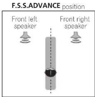
Using Stream Direct
Use the Stream Direct modes when you want to hear the truest possible reproduction of a source. All unnecessary signal processing is bypassed.
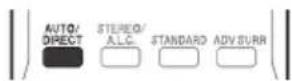
- While listening to a source, press AUTO/DIRECT to select Stream Direct mode.
- AUTO SURROUND - See Auto playback on page 63.
- DIRECT - Sources are heard according to the settings made in the Surround Setup (speaker setting, channel level, speaker distance), as well as with dual mono settings. You will hear sources according to the number of channels in the signal.
- PURE DIRECT - Analog and PCM sources are heard without any digital processing.2
Using the Sound Retriever
When audio data is removed during the compression process, sound quality often suffers from an uneven sound image. The Sound Retriever feature employs new DSP technology that helps bring CD quality sound back to compressed 2-channel audio by restoring sound pressure and smoothing jagged artifacts left over after compression.
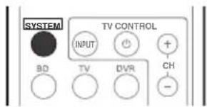
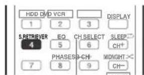
Press, the Press
S.RETRIEVER
to switch the sound retriever on or off.

Note
1 In the DIRECT mode, Phase Control, Acoustic Calibration EQ, Sound Delay, Auto Delay, LFE Attenuate and Center image functions are available.
2 There are cases where a brief noise is heard before playback of sources other than PCM. Please select AUTO SURROUND or DIRECT if this is a problem.
3 The Sound Retriever is only applicable to 2-channel sources.
Listening with Acoustic Calibration EQ
- Default setting: ON
You can listen to sources using the Acoustic Calibration Equalization set in Automatically setting up for surround sound (MCACC) on page 51. Refer to these pages for more on Acoustic Calibration Equalization.
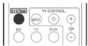
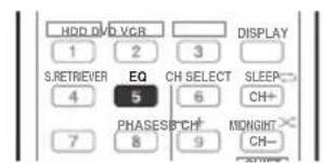
- While listening to a source, press SYSTEM, then press EQ to switch the Acoustic Calibration EQ on or off.
Better sound using Phase Control
This system's Phase Control feature uses phase correction measures to make sure your sound source arrives at the listening position in phase, preventing unwanted distortion and/or coloring of the sound (see illustration below).
During multichannel playback, LFE (Low-Frequency Effects) signals as well as low-frequency signals in each channel are assigned to the subwoofer or other the subwoofer and the most appropriate speaker. At least in theory, however, this type of processing involves a group delay that varies with frequency, resulting in phase distortion where the low-frequency sound is delayed or
muffled by the conflict with other channels. With the Phase Control mode switched on, this system can reproduce powerful bass sound without deteriorating the quality of the original sound (see illustration below).
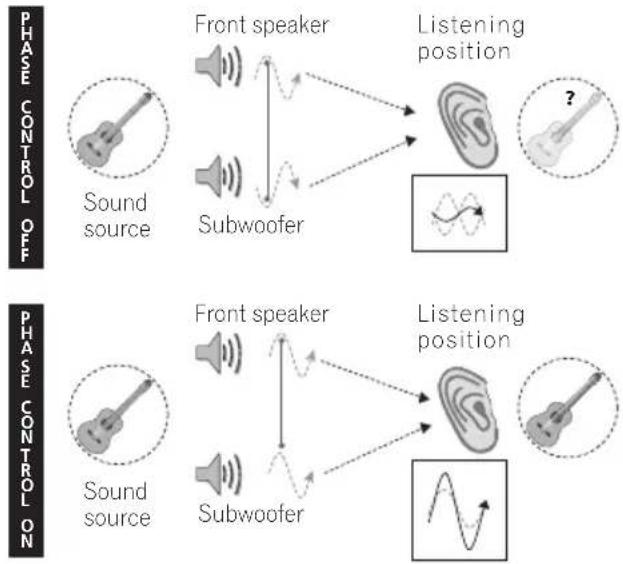
Phase Control technology provides coherent sound reproduction through the use of phase matching for an optimal sound image at your listening position. The default setting is on and we recommend leaving Phase Control switched on for all sound sources.
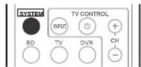
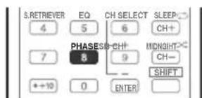
- Press, then press PHASE to switch on phase correction.
Note
1 You can't use Acoustic Calibration EQ with Stream Direct mode.
2 - Phase matching is a very important factor in achieving proper sound reproduction. If two waveforms are 'in phase', they crest and trough together, resulting in increased amplitude, clarity and presence of the sound signal. If a crest of a wave meets a trough (as shown in the upper section of the diagram above) then the sound will be 'out of phase' and an unreliable sound image will be produced.
- If your subwoofer has a phase control switch, set it to the plus (+) sign (or 0^ ). However, the effect you can actually feel when PHASE CONTROL is set to ON on this system depends on the type of your subwoofer. Set your subwoofer to maximize the effect. It is also recommended you try changing the orientation or the place of your subwoofer.
- Set the built-in lowpass filter switch of your subwoofer to OFF. If this cannot be done on your subwoofer, set the cutoff frequency to a higher value.
- If the speaker distance is not properly set, you may not have a maximized PHASE CONTROL effect.
- When the PURE DIRECT mode is selected, the PHASE CONTROL mode cannot be set to ON.
Functions when surround back speakers are connected
For HTP-710/HTP-610 (In the case of the HTP-FS510 and HTP-SB510, it may be necessary to connect the optional speaker systems as well.):
When surround back speakers are connected to a surround back amplifier, 7.1 ch surround sound is possible. In this case, it is possible to select a listening mode and make other settings supported by 7.1 ch playback.
See also Using surround back channel processing on page 68.
Surround sound mode
With two channel sources, you can select from:
DOLBY PLIIx MOVIE - Up to 7.1 channel sound, especially suited to movie sources
DOLBY PLIIx MUSIC - Up to 7.1 channel sound, especially suited to music sources
DOLBY PLIIx GAME - Up to 7.1 channel sound, especially suited to video games
- NEO:6 CINEMA - 6.1 channel sound, especially suited to movie sources
NEO:6 MUSIC - 6.1 channel sound, especially suited to music sources
DOLBY PRO LOGIC - 4.1 channel surround sound (sound from the surround speakers is mono)
With multichannel sources, if you have connected surround back speaker(s) and have selected SB ON, you can select (according to format):
DOLBY PLIIx MOVIE - See above (only available when you're using two surround back speakers)
DOLBY PLIIx MUSIC - See above
DOLBY DIGITAL EX - Creates surround back channel sound for 5.1 channel sources and provides pure decoding for 6.1 channel sources (like Dolby Digital Surround EX)
- DTS-ES - Allows you to hear 6.1 channel playback with DTS-ES encoded sources
- DTS NEO:6 - Allows you to hear 6.1 channel playback with DTS encoded sources

Note
1 If surround back channel processing (page 68) is switched off, or the surround back speakers are set to NO, DOLBY PLIIx becomes DOLBY PLII (5.1 channel sound).
- In modes that give 6.1 channel sound, the same signal is heard from both surround back speakers.
2 When listening to 2-channel sources in DOLBY PLIIx MUSIC mode, there are three further parameters you can adjust: C.WIDTH, DIMEN., and PNRM.. See Setting the Audio options on page 69 to adjust them.
3 When listening to 2-channel sources in NEO:6 CINEMA or NEO:6 MUSIC mode, you can also adjust the C.IMG effect (see Setting the Audio options on page 69).
Using surround back channel processing
- Default setting: SB ON
You can have the system automatically use 6.1 or 7.1 decoding for 6.1 encoded sources (for example, Dolby Digital EX or DTS-ES), or you can choose to always use 6.1 or 7.1 decoding (for example, with 5.1 encoded material). With 5.1 encoded sources, a surround back channel will be generated, but the material may sound better in the 5.1 format for which it was originally encoded (in which case, you can simply switch surround back channel processing off).
- With a 7.1-channel surround system, audio signals that have undergone matrix decoding processing through surround back channel processing to which the Up Mix function is added are output from the surround back speakers.
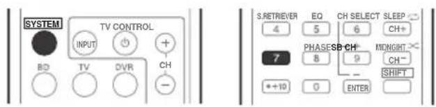
- Press, then press SB CH repeatedly to cycle the surround back channel options.
Each press cycles through the options as follows:
- SB ON - Matrix decoding processing for generating the surround back component from the surround component is turned on.
- SBAUTO - Matrix decoding processing for generating the surround back component from the surround component is switched automatically. Matrix decoding processing is only performed when surround back channel signals are detected in the input signals.
- SB OFF - Matrix decoding processing for generating the surround back component from the surround component is turned off.
Setting the Up Mix function
In a 7.1-channel surround system with surround speakers placed directly at the sides of the listening position, the surround sound of 5.1-channel sources is heard from the side. The Up Mix function mixes the sound of the surround speakers with the surround back speakers so that the surround sound is heard from diagonally to the rear as it should be.
- Using the Up Mix function is effective when the speakers in the 7.1-channel surround system are set up as recommended in the example below.
Depending on the positions of the speakers and the sound source, in some cases it may not be possible to achieve good results. In this case, set the setting to OFF.
1 Switch the system into standby.
2 While holding down the PRESET + on the front panel, and hold the STANDBY/ON for about two seconds.
UP MIX: OFF appears and the Up Mix function turns off. If you want to turn this function on, perform steps 1 and 2 again.
- When set to ON, the UP MIX indicator on the front panel lights.

Note
1 - Set to ON regardless of this setting when playing DTS-HD signals.
- May automatically be set to OFF even when set to ON, depending on the input signal and listening mode.
Setting the Audio options
There are a number of additional sound settings you can make using the AUDIO PARAMETER menu. The defaults, if not stated, are listed in bold.

Important
Note that if a setting doesn't appear in the AUDIO PARAMETER menu, it is unavailable due to the current source, settings and status of the system.
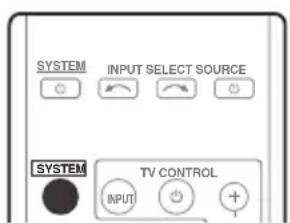
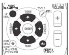
1 Press qytbemote control, then press AUDIO PARAMETER button.
2 U 12 to select the setting you want to adjust.
Depending on the current status/mode of the system, certain options may not be able to be selected. Check the table below for notes on this.
3 U / to set it as necessary.
See the table below for the options available for each setting.
4 P r RETURNsto confirm and exit the menu.
Setting What it does Option(s)
| EQ (Acoustic Calibration EQ) | Switches on/off the effect of Acoustic Calibration EQ. ON | |
| OFF | ||
| S.DELAY (Sound Delay) | Some monitors have a slight delay when showing video, so the soundtrack will be slightly out of sync with the picture. By adding a bit of delay, you can adjust the sound to match the presentation of the video. | 0.0 to 9.0 (frames) 1 second = 25 frames (PAL) Default: 0.0 |
| MIDNIGHTa | Allows you to hear effective surround sound of movies at low volumes. | MID OFF |
| MIDNIGHT | ||
| S.RTVb (Sound Retriever) | When audio data is removed during the WMA/MP3c compression process, sound quality often suffers from an uneven sound image. The Sound Retriever feature employs new DSP technology that helps bring CD quality sound back to compressed 2-channel audio by restoring sound pressure and smoothing jagged artifacts left over after compression. | OFF |
| ON | ||
| Setting What it does Option(s) | ||
| DUAL MONOd | Specifies how dual mono encoded Dolby Digital soundtracks should be played. | CH1 - Channel 1 is heard only |
| CH2 - Channel 2 is heard only | ||
| CH1 CH2 - Both channels heard from front speakers | ||
| DRC (Dynamic Range Control) | Adjusts the level of dynamic range for movie soundtracks optimized for Dolby Digital, DTS, Dolby Digital Plus, Dolby TrueHD, DTS-HD and DTS-HD Master Audio (you may need to use this feature when listening to surround sound at low volumes). | AUTOe |
| MAX | ||
| MID | ||
| OFF | ||
| LFE ATT (LFE Attenuate) | Some Dolby Digital and DTS audio sources include ultra-low bass tones. Set the LFE attenuator as necessary to prevent the ultra-low bass tones from distorting the sound from the speakers. The LFE is not limited when set to 0 dB, which is the recommended value. When set to -10 dB, the LFE is limited by the respective degree. When OFF is selected, no sound is output from the LFE channel. | LFEATT 0 (0 dB) |
| LFEATT 10 (-10 dB)/LFEATT ** (OFF) | ||
| HDMI (HDMI Audio) | Specifies the routing of the HDMI audio signal out of this system (amp) or through to a TV. When THRU is selected, no sound is output from this system. | AMP |
| THRU | ||
| A.DLY (Auto Delay) | This feature automatically corrects the audio-to-video delay between components connected with an HDMI cable. The audio delay time is set depending on the operational status of the display connected with an HDMI cable. The video delay time is automatically adjusted according to the audio delay timef | OFF |
| ON | ||
| C.WIDTh9 (Center Width) (Applicable only when using a center speaker) | Spreads the center channel between the front right and left speakers, making it sound wider (higher settings) or narrower (lower settings). | 0 to 7 Default: 3 |
| DIMEN.g (Dimension) | Adjusts the surround sound balance from front to back, making the sound more distant (minus settings), or more forward (positive settings). | -3 to +3 Default: 0 |
Setting What it does Option(s)
| PNRM.9 (Panorama) | Extends the front stereo image to include surround speakers for a ‘wraparound’ effect. | OFF |
| ON | ||
| C.IMGh (Center image) (Applicable only when using a center speaker) | Adjust the center image to create a wider stereo effect with vocals. Adjust the effect from 0 (all center channel sent to front right and left speakers) to 10 (center channel sent to the center speaker only). | 0 to 10 Default: 3 (NEO:6 MUSIC), 10 (NEO:6 CINEMA) |
a. You can change the MIDNIGHT option at any time by using MIDNIGHT button.
b. You can change the Sound Retriever feature at any time by using S.RETRIEVER button.
c. WMA and MP3 playback available only via iPod/USB input.
d. This setting works only with dual mono encoded Dolby Digital and DTS soundtracks.
e. The initial set AUTO is only available for Dolby TrueHD signals. Select MAX or MID for signals other than Dolby TrueHD.
f. This feature is only available when the connected display supports the automatic audio/video synchronizing capability ('lip-sync') for HDMI. If you find the automatically set delay time unsuitable, set A.DLY to OFF and adjust the delay time manually. For more details about the lip-sync feature of your display, contact the manufacturer directly.
g. Only available with 2-channel sources in DOLBY PLII MUSIC mode.
h. Only when listening to 2-channel sources in NEO:6 CINEMA and NEO:6 MUSIC mode.
Chapter 8
The System Setup menu
Using the System Setup menu
The following section shows you how to make detailed settings to specify how you're using the system, and also explains how to fine-tune individual speaker system settings to your liking.

Important
- The OSD will not appear if you have connected using the HDMI output to your TV. Use composite connections for system setup.
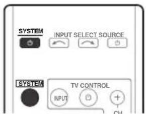
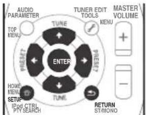
1 Switch on the system and your TV.
Use the 品 SYSTEM button to switch on.
Switch the TV input so that it connects to the system in analog.
2 Press dyheF note control, then press the SETUP button.1
An on-screen display (OSD) appears on your TV. Use / / / and ENTER on the remote control to navigate through the screens and select menu items. Press RETURN to confirm and exit the current menu.
3 Select the setting you want to adjust.
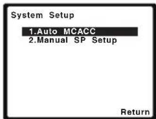
- Auto MCACC - This is a quick and effective automatic surround setup (see Automatically setting up for surround sound (MCACC) on page 51).
- Manual SP Setup - Specify the number, distance and overall balance of the speakers you've connected (see Manual speaker setup below).
Manual speaker setup
These settings are designed to fine-tune your system, but if you're satisfied with the settings made in Automatically setting up for surround sound (MCACC) on page 51, it isn't necessary to make all of these settings.

CAUTION
- The test tones used in the System Setup are output at high volume.

Note
1 - You can't use the System Setup menu when the iPod/USB input is selected.
- Press SETUP at any time to exit the System Setup menu.
1 Select 'Manual SP Setup' then press ENTER.
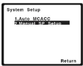
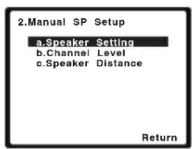
2 Select the setting you want to adjust. If you are doing this for the first time, you may want to adjust these settings in order:
- Speaker Setting - Specify the number of speakers you've connected (see below).
- Channel Level - Adjust the overall balance of your speaker system (see below).
- Speaker Distance - Specify the distance of your speakers from the listening position (see page 74).
3 Make the adjustments necessary for each setting, pressing RETURN to confirm after each screen.
Speaker Setting
Use this setting to specify your speaker configuration (number of speakers). It is a good idea to make sure that the settings made in Automatically setting up for surround sound (MCACC) on page 51 are correct.
1 Select 'Speaker Setting' from the Manual SP Setup menu.
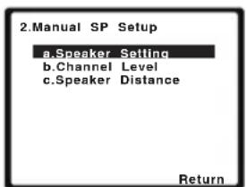
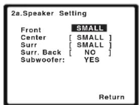
2 Choose the set of speakers that you want to set then select a speaker setting.
Use / to select the number of each of the following speakers:
- Front - This setting cannot be changed, since it is already optimized for this unit.
- Center - Select SMALL if you connect a center speaker. If you didn't connect a center speaker, choose NO (the center channel is sent to the other speakers).
- Surr - Select SMALL if you connect surround speakers. If you didn't connect surround speakers choose NO (the sound of the surround channels is sent to the other speakers).
- Surr. Back - Select the number of surround back speakers you have (one, two or none). If you didn't connect surround back speakers choose NO.
- Subwoofer - This setting cannot be changed, since it is already optimized for this unit.
3 When you're finished, press RETURN. You return to the Manual SP Setup menu.

Tip
For HTP-FS510:
If optional speaker systems are not connected, set Center and Surr to NO.
For HTP-SB510:
If optional speaker systems are not connected, set Surr to NO.
Channel Level
Using the channel level settings, you can adjust the overall balance of your speaker system, an important factor when setting up a home theater system.

Note
1 If the surround speakers are set to NO, the surround back speakers will automatically be set to NO.
- If you select one surround back speaker only, make sure that additional amplifier is hooked up to the PRE OUT SURROUND BACK L (Single) terminal.
1 Select 'Channel Level' from the Manual SP Setup menu.
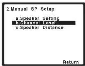
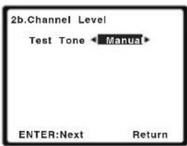
2 Select a setup option.
- Manual - Move the test tone manually from speaker to speaker and adjust individual channel levels.
- Auto - Adjust channel levels as the test tone moves from speaker to speaker automatically.
3 Confirm your selected setup option.
The test tones will start after you press ENTER. After the volume increases to the reference level, test tones will be output.
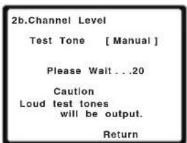
4 Adjust the level of each channel using / .
If you selected Manual, use ↑/↓ to switch speakers. The Auto setup will output test tones in the order shown on-screen:
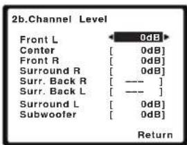
Adjust the level of each speaker as the test tone is emitted.

Note
If you are using a Sound Pressure Level (SPL) meter, take the readings from your main listening position and adjust the level of each speaker to 75 dB SPL (C-weighting/slow reading).
- The subwoofer test tone is output at low volumes. You may need to adjust the level after testing with an actual soundtrack.
Chapter 9
Controlling the rest of your system
Setting the remote to control other components
Most components can be assigned to one of the MULTI CONTROL buttons using the component's manufacturer preset code stored in the remote.
However, please note that there are cases where only certain functions may be controllable after assigning the proper preset code, or the codes for the manufacturer in the remote control will not work for the model that you are using.

Note
- You can cancel or exit any of the steps by pressing SYSTEM.
After one minute of inactivity, the remote automatically exits the operation.
Selecting preset codes directly
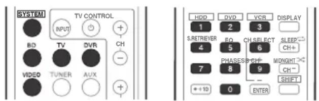
1 While pressing the buyoutpress and hold the '1' button for three seconds.
2 Press the MULTI CONTROL button for the component you want to control.
The component can be assigned to the BD, TV, DVR or VIDEO button.
3 Use the number buttons to enter the preset code.
You can find the preset codes on page 79. If the correct code has been input the power of the component being input will turn on or off. The power of the component being input will only turn on or off if that component is able to be turned on directly by remote control.
4 Repeat steps 2 through 3 to try a different code, or to enter a code for another component you want to control.
5 When you're done, press. SYSTEM
Clearing all the remote control settings
You can clear all presets and restore the factory default settings.
- While pressing the bEyGnEpress and hold the '0' button for three seconds.
Default preset codes
| MULTI CONTROL button | Preset code |
| BD | 2126 |
| TV | 0120 |
| DVR | 2121 |
| VIDEO | 1120 |
Note
TV control codes (for example, codes for TV, CATV, Satellite TV or DTV) can only be assigned to the TV button.
Controls for TVs
This remote control can control components after entering the proper codes or teaching the system the commands (see Controlling the rest of your system on page 75 for more on this). Use the MULTI CONTROL buttons to select the component
- The TV CONTROL buttons on the remote control are dedicated to control the TV assigned to the TV button.
Button(s) Function Components
| TV CONTROL | Switches the DTV on or off. DTV |
| Switches the TV or CATV between standby and on. Cable TV/Satellite TV/TV | |
| TV CONTROL INPUT | Switches the TV input. (Not possible with all models.) TV |
| TV CONTROL CH +/- | Selects channels. Cable TV/Satellite TV/TV/DTV |
| TV CONTROL VOL +/- | Adjust the TV volume. Cable TV/Satellite TV/TV/DTV |
| SOURCE | Press to switch the component assigned to the TV button on or off. Cable TV/Satellite TV/TV/DTV |
| DTV/TV | Switches between the DTV and analog TV input modes for Pioneer TVs. DTV/TV |
| TOP MENU | Switches TEXT ON/OFF for TVs. TV |
| HOME MENU | Use as the GUIDE button for navigating. Cable TV/Satellite TV/TV/DTV |
| RETURN | Use to select closed captioning with DTV. DTV |
| Number buttons | Use to select a specific TV channel. Cable TV/Satellite TV/TV/DTV |
| +10 button | Use to add a decimal points when selecting TV channels. DTV |
| ENTER | Use to enter a channel. Cable TV/Satellite TV/TV/DTV |
| MENU | Press to display the DTV menu. DTV |
| Select the menu screen. Cable TV/Satellite TV/TV | |
| ←→↓↑& ENTER | Press to select or adjust and navigate items on the menu screen. Cable TV/Satellite TV/TV/DTV |
| CH +/- | Selects channels. Cable TV/Satellite TV/TV/DTV |
Controls for other components
This remote control can control these components after entering the proper codes or teaching the system the commands (see Controlling the rest of your system on page 75 for more on this). Use the MULTI CONTROL buttons to select the component.
| Button(s) Function Components | ||
| SOURCE Press to switch the component between standby and on. | BD/DVD player, DVR, VCR | |
| Press to return to the start of the current track. | BD/DVD player, DVR, VCR | |
| Repeated presses skips to the start of previous tracks. | ||
| Press to advance to the start of the next track. | BD/DVD player, DVR, VCR | |
| Repeated presses skips to the start of following tracks. | ||
| Pause playback or recording. BD/DVD player, DVR, VCR | ||
| Start playback. BD/DVD player, DVR, VCR | ||
| Hold down for fast forward playback. | BD/DVD player, DVR, VCR | |
| Hold down for fast reverse playback. | BD/DVD player, DVR, VCR | |
| Stops playback (on some models, pressing this when the disc is already stopped will cause the disc tray to open). | BD/DVD player, DVR, VCR | |
| Number buttons | Directly access tracks on a program source. | VCR |
| Use to enter a title/chapter/track number. | BD/DVD player, DVR | |
| +10 button | Selects tracks higher than 10. (For example, press +10 then 3 to select track 13.) | BD/DVD player, DVR |
| ENTER | Use as the ENTER button. | BD/DVD player |
| Displays the DISC NAVI screen for DVD recorder. | DVR | |
| DISPLAY | Press to display information. | BD/DVD player, DVR |
| TOP MENU | Displays the disc 'top' menu of a BD/DVD player. | BD/DVD player, DVR |
| MENU | Displays menus for the current BD/DVD player or DVD recorder you are using. | BD/DVD player, DVR |
| ←→↓↑, ENTER & RETURN | Navigates BD/DVD menu/options. | BD/DVD player, DVR |
| HOME MENU | Displays the HOME MENU. | BD/DVD player, DVR |
| CH +/- | Selects channels. | DVR, VCR |
| HDD (SHIFT + 1) | Switches to the hard disk controls when using an HDD/ DVD recorder. | HDD/DVD/VCR recorder |
Controlling the rest of your system
| Button(s) Function Components | ||
| DVD (SHIFT + 2) | Switches to the DVD controls when using an HDD/DVD recorder. | HDD/DVD/VCR recorder |
| VCR (SHIFT + 3) | Switches to the VCR controls when using an HDD/DVD/ VCR recorder. | HDD/DVD/VCR recorder |
Preset Code List
You should have no problem controlling a component if you find the manufacturer in this list, but please note that there are cases where codes for the manufacturer in the list will not work for the model that you are using. There are also cases where only certain functions may be controllable after assigning the proper preset code.
BD/DVD/DVR
Manufacturer Code
AEG 2093
Aiwa 2054
Akai 2001
Akura 2091
Alba 2027, 2038, 2048
Amitech 2093
AMW 2094
Awa 2094
Bang & Olufsen 2096
Bellagio 2094
Best Buy 2090
Brainwave 2093
Brandt 2017, 2044
Bush 2027, 2048, 2082, 2089
Cambridge Audio 2085
CAT 2087, 2088
Centrum 2088
CGV 2085, 2093
Cinetec 2094
Clatronic 2089
Coby 2095
Conia 2082
Continental Edison 2094
Crown 2093
C-Tech 2086
CyberHome 2008, 2037
Daenyx 2094
Daewoo 2035, 2059, 2093, 2094
Daewoo International 2094
Dalton 2092
Dansai 2084, 2093
Daytek 2010, 2033, 2094
Dayton 2094
DEC 2089
Decca 2093
Denon 2066, 2068
Denver 2069, 2089, 2091, 2095
Denzel 2083
Diamond 2085, 2086
DK Digital 2034
Dmtech 2000
Dual 2083
DVX 2086
Easy Home 2090
Eclipse 2085
Electrohome 2093
Elin 2093
Elta 2047, 2093
Enzer 2083
Finlux 2085, 2093
Gericom 2050
Global Solutions 2086
Global Sphere 2086
Goodmans 2027, 2070, 2089
Graetz 2083
Grundig 2053
Grunkel 2093
H&B 2089
Haaz 2085, 2086
HiMAX 2090
Hitachi 2015, 2083, 2090
Innovation 2002
JVC 2024, 2041, 2057
Kansai 2095
Kennex 2093
Kenwood 2051
KeyPlug 2093
Kiiro 2093
Kingavon 2089
Kiss 2083
Koda 2089
KXD 2090
Lawson 2086
Lecson 2084
Lenco 2089, 2093
LG 2016, 2020, 2040, 2043, 2065, 2076
Life 2002
Lifetec 2002
Limit 2086
Loewe 2056
LogicLab 2086
Magnavox 2089
Majestic 2095
Marantz 2062
Marquant 2093
Matsui 2044
Mecotec 2093
Medion 2002
MiCO 2085
Micromaxx 2002
Microstar 2002
Minoka 2093
Mizuda 2089, 2090
Monyka 2083
Mustek 2006
Mx Onda 2085
Naiko 2093
Neufunk 2083
Nevir 2093
NU-TEC 2082
Onkyo 2072
Optim 2084
Optimus 2004
Orava 2089
Orbit 2094
Orion 2061
P&B 2089
Pacific 2086
Panasonic 2018, 2019,
2026, 2032, 2036, 2075
Philips 2005, 2011, 2022
2023, 2031, 2039, 2062
Pioneer 2004, 2012, 2014
2049, 2120, 2121, 2122
2123, 2124, 2125, 2126
Pointer 2093
Portland 2093
Powerpoint 2094
Prosonic 2095
Provision 2089
Raite 2083
RedStar 2091, 2093, 2095
Reoc 2086
Roadstar 2021, 2089
Ronin 2094
Rowa 2082
Rownsonic 2088
Saba 2017, 2044
Sabaki 2086
Saivod 2093
Samsung 2015, 2042, 2063, 2078, 2081
Sansui 2085, 2086, 2093
Sanyo 2045, 2071
ScanMagic 2006
Schaub Lorenz 2093
Schneider 2000
Scientific Labs 2086
Scott 2025, 2092
SEG2021,2083,2086,2094
Sharp 2002, 2046, 2079
Sigmatek 2090
Silva 2091
Singer 2085, 2086
Skymaster 2058, 2086
Skyworth 2091
Slim Art 2093
SM Electronic 2086
Sony 2009, 2013, 2028, 2029, 2030, 2055, 208
Soundmaster 2086
Soundmax 2086
Spectra 2094
Standard 2086
Star Cluster 2086
Starmedia 2089
Sunkai 2093
Supervision 2086
Synn 2086
Tatung 2035, 2093
TCM 2002
Teac 2067, 2082, 2086
Tec 2091
Technika 2093
Telefunken 2088
Tensai 2093
Tevion 2002, 2086, 2092
Thomson 2003, 2017.
2060, 2064
Tokai 2083, 2091
Toshiba 2007, 2061, 2073, 2074, 2077
TRANScontinentns 2094
Trio 2093
TruVision 2090
Wharfedale 2085, 2086
Xbox 2003
Xlogic 2086, 2093
XMS 2093
Yamada 2094
Yamaha 2011
Yamakawa 2083, 2094
Yukai 2006, 2052
TV
Manufacturer Code
A.R. Systems 0040
Acme 0026
Acura 0027, 0039
ADC 0025
Admiral 0023, 0024, 0025, 0030, 0031
Adyson 0026, 0113, 0114
Agashi 0113, 0114
Agazi 0025
Aiko 0026,0027,0039, 0040,0113,0114
Aim 0040
Aiwa 0084
Akai 0027,0028,0034, 0037,0039,0040,0113, 0114
Akiba 0028, 0040
Akura 0025,0028,0039 0040
Alaron 0113
Alba 0010,0026,0027, 0028,0032,0035,0037, 0039,0040,0075,0078, 0088,0113
Alcyon 0017
Allorgan 0114
Allstar 0034,0040
AMOI 0109
Amplivision 0010,0026, 0041,0114
Amstrad 0025,0027,0028, 0039,0040
Anam 0027
Anglo 0027,0039
Anitech 0017.0025,0027, 0039.0040
Ansonic 0010,0018,0027, 0029,0039,0040
Arcam 0113, 0114
Arcam Delta 0026
Aristona 0034, 0037, 0040
Arthur Martin 0041
ASA 0023, 0031
Asberg 0017, 0034, 0040
Astra 0027
Asuka 0025, 0026, 0028, 0113, 0114
Atlantic 0026,0034,0037 0040.0113
Atori 0027,0039
Auchan 0041
Audiosonic 0010,0026, 0027,0028,0034,0037, 0040,0114
AudioTon 0010, 0026.0114
Ausind 0017
Autovox 0017,0023,0025, 0026,0114
Awa 0113,0114
Baird 0114
Bang & Olufsen 0023, 0115
Basic Line 0027,0028, 0034,0039,0040,0114
Bastide 0026.0114
Baur 0037,0040
Bazin 0114
Beko 0010,0035,0040, 0060
Beng 0104
Beon 0034,0037,0040
Best 0010
Bestar 0010, 0034, 0040
Binatone 0026, 0114
Blue Sky 0028, 0040
Blue Star 0036
Boots 0026, 0114
BPL 0036,0040
Brandt 0033,0038,0042, 0044
Brinkmann 0040
Brionvega 0023,0034, 0037,0040
Britannia 0026, 0113, 0114
Bruns 0023
BTC 0028
Bush 0027,0028,0030 0032,0034,0036,0037 0039,0040,0065,0078 0114
Capsonic 0025
Carena 0040
Carrefour 0032
Cascade 0027, 0039, 0040
Casio 0106
Cathay 0034,0037,0040
CCE 0114
Centurion 0034,0037,0040
Century 0023
CGE 0010, 0017
Cimline 0027,0039
City 0027, 0039
Clarivox 0037
Clatronic 0010,0017,0025, 0026,0027,0028,0034, 0035,0039,0040,0114
CMS 0113
CMS Hightec 0114
Concorde 0027,0039
Condor 0010, 0026, 0034, 0035, 0039, 0040, 0113
Contec 0026,0027,0032, 0039,0113
Continental Edison 0033
Cosmel 0027, 0039
Crosley 0017, 0023
Crown 0010,0017,0027, 0034,0035,0037,0039, 0040
CS Electronics 0026, 0028, 0113
CTC Clatronic 0029
Cybertron 0028
Daewoo 0013,0026,0027, 0034,0039,0040,0054, 0064,0091,0113,0114
Dainichi 0028, 0113
Dansai 0025,0034,0037 0040,0113,0114
Dantax 0010, 0037
Dawa 0040
Daytron 0027, 0039
De Graaf 0030
Decca 0026,0034.0037 0040.0114
Denver 0098, 0103
Desmet 0034,0037,0040
Diamant 0040
Diamond 0113
Dixi 0027,0034,0037,0039, 0040.0114
DTS 0027,0039
Dual 0026, 0040, 0114
Dual-Tec 0026, 0027
Dumont 0023,0026,0029 0114
Dux 0037
Dynatron 0034,0037,0040
Elbe 0010, 0018, 0040, 0114
Elcit 0023
Electa 0036
ELECTROTECH 0027
Elin 0026,0034,0037,0039, 0040,0113
Elite 0028,0034,0040
Elman 0029
Elta 0027, 0039, 0113
Emerson 0010, 0023, 0040
Epson 0101
Erres 0034, 0037, 0040
ESC 0114
Etron 0027
Eurofeel 0025, 0114
Euroline 0037
Euroman 0010,0025,0026, 0034.0040.0113.0114
Europhon 0026,0029, 0034.0040.0113.0114
Expert 0041
Exquisit 0040
Fenner 0027, 0039
Ferguson 0033,0037,0038, 0042
Fidelity 0026,0030,0040, 0113
Filsai 0114
Finlandia 0030
Finlux 0017,0023,0026, 0029,0034,0037,0040, 0114
Firstline 0026,0027,0034, 0039,0040,0113,0114
Fisher 0010,0023,0026, 0032,0035,0114
Flint 0034.0040
Formenti 0017,0023,0024, 0026,0037,0113
Formenti/Phoenix 0113
Fortress 0023.0024
Fraba 0010, 0040
Friac 0010
Frontech 0025,0027,0030. 0031.0039.0114
Fujitsu 0114
Fujitsu General 0114
Funai 0025
Galaxy 0035.0040
Galaxis 0010, 0040
GBC 0027, 0032, 0039
Geant Casino 0041
GEC 0026,0031,0034, 0037,0040,0114
Geloso 0027, 0030, 0039
General Technic 0027, 0039
Genexxa 0028,0031,0034, 0040
Giant 0114
GoldHand 0113
Goldline 0040
GoldStar 0010,0026,0027, 0030,0034,0037,0039, 0040.0113.0114
Goodmans 0025,0027, 0032,0034,0037,0039, 0040.0107.0114
Gorenje 0010, 0035
GPM 0028
Graetz 0031
Granada 0017,0026,0030, 0032,0034,0037,0040, 0041,0114
Grandin 0027,0028,0036 0037
Gronic 0114
Grundig 0009, 0010, 0017, 0040, 0047
Halifax 0025,0026,0113 0114
Hampton 0026, 0113, 0114
Hanseatic 0010,0018, 0026,0027,0032,0034, 0037,0039,0040,0114
Hantarex 0027, 0039, 0040
Hantor 0040
Harwood 0039, 0040
HCM 0025,0026,0027, 0036,0039,0040,0114
Hema 0039, 0114
Higashi 0113
HiLine 0040
Hinari 0027,0028,0032, 0034,0037,0039,0040
Hisawa 0028,0036,0041
Hitachi 0022, 0026, 0030, 0031, 0032, 0040, 0076, 0111, 0114
Hornyphon 0034, 0040
Hoshai 0028
Huanyu 0026, 0113
Hygashi 0026, 0113, 0114
Hyper 0026,0027,0039 0113.0114
Hypson 0025,0026,0034, 0036,0037,0040,0041, 0114
Iberia 0040
ICE 0025,0026,0027,0028, 0034,0039,0040,0113, 0114
ICeS 0113
Imperial 0010,0017,0031, 0034,0035,0040
Indiana 0034, 0037, 0040
Ingelen 0031
Ingersol 0027, 0039
Inno Hit 0017,0026,0027, 0028,0034,0037,0039, 0040,0114
Innovation 0025, 0027
Interactive 0010
Interbuy 0027, 0039
Interfunk 0010,0023,0031, 0034,0037,0040
International 0113
Intervention 0010,0025, 0026,0029,0040,0114
Irradio 0017,0027,0028, 0034,0037,0039,0040
Isukai 0028, 0040
ITC 0026,0114
ITS 0028,0034,0036,0040, 0113
ITT 0027,0031
ITV0027,0037,0040
JVC0019,0020,0032,0034 0077
Kaisui 0026,0027,0028, 0036,0039,0040,0113, 0114
Kamosonic 0026
Kamp 0026, 0113
Kapsch 0031
Karcher 0010,0026,0027, 0037,0040
Kawasho 0113
Kendo 0010,0029,0030 0040
KIC 0114
Kingsley 0026, 0113
Kneissel 0010, 0018, 0040
Kolster 0034, 0040
Konka 0028
Manesth 0025,0026,0034, 0037.0040.0114
Marantz 0034, 0037, 0040
Marelli 0023
Mark 0034,0037,0039, 0040,0113,0114
Masuda 0114
Matsui 0026,0027,0030, 0032,0034,0037,0039, 0040,0114
Mediator 0034, 0037, 0040
Medion 0025, 0027, 0040
M-Electronic 0039,0040, 0113,0114
Melvox 0041
Memorex 0027, 0039
Memphis 0027, 0039
Mercury 0039, 0040
Metz 0023
Micromaxx 0025, 0027
Microstar 0025, 0027
Minerva 0017
Minoka 0034, 0040
Mitsubishi 0023,0032, 0034,0040,0085
Mivar 0010, 0017, 0018, 0026, 0113, 0114
Motion 0017
MTC 0010, 0113
Multi System 0037
Multitech 0010,0026, 0027,0029,0030,0032, 0037,0039,0040,0113, 0114
Murphy 0026, 0113
Naonis 0030
NEC 0032.0114
Neckermann 0010,0023, 0026,0030,0034,0035, 0037,0040,0114
NEI 0034,0037,0040
Neufunk 0039, 0040
New Tech 0027,0034, 0039,0040,0114
New World 0028
Nicamagic 0026, 0113
Nikkai 0025,0026,0028, 0034,0037,0039,0040, 0113,0114
Nobliko 0017,0026,0029 0113
Nokia 0031
Nordic 0114
Nordmende 0023,0031, 0033.0034
Nordvision 0037
Novatronic 0040
Oceanic 0031, 0041
Okano 0010.0035.0040
ONCEAS 0026
Opera 0040
Orbit 0034, 0040
Orion 0027,0034,0037 0039,0040,0079
Online 0040
Osaki 0025, 0026, 0028, 0040, 0114
Oso 0028
Otto Versand 0024,0026, 0032,0034,0036,0037, 0040,0114
Pael 0026, 0113
Palladium 0010, 0026, 0035. 0040. 0114
Palsonic 0114
Panama 0025,0026,0027, 0039,0040,0113,0114
Panasonic 0008,0031, 0040,0043,0049,0099, 0102,0121
Panavision 0040
PatheCinema0010,0018, 0026.0041,0113
Pausa 0027, 0039
Perdio 0040, 0113
Perfekt 0040
Philco 0010, 0017, 0023, 0040
Philharmonic 0026, 0114
Philips 0000,0002,0023, 0026,0034,0037,0040, 0045,0048,0050,0055, 0056,0058,0059,0067, 0068,0080,0081,0087, 0090,0097,0100
Phoenix 0010,0023.0034, 0037,0040,0113
Phonola 0023,0034,0037 0040.0113
Pioneer 0010,0031,0033, 0034.0037,0040,0120
Plantron 0025,0034,0039, 0040
Playsonic 0114
Poppy 0027, 0039
Prandoni-Prince 0017, 0030
Precision 0026.0114
Prima 0027,0031,0039
Profex 0027, 0039
Profi-Tronic 0034, 0040
Proline 0034, 0040
Prosonic 0010,0026,0037 0040,0113,0114
Protech 0025,0026,0027 0029,0034,0037,0114
Provision 0037, 0040
Pye 0034, 0037, 0040, 0083
Pymi 0027, 0039
Quandra Vision 0041
Quelle 0025,0026,0034, 0037,0040,0114
Questa 0032
Radialva 0040
Radio Shack 0040
Radiola 0034, 0037, 0040, 0114
Radiomarelli 0023, 0040
Radiotone 0010,0034, 0039,0040
Rank 0032
Recor 0040
Redstar 0040
Reflex 0040
Revox 0010,0034,0037 0040
Rex 0025,0030,0031
RFT 0010, 0018, 0023
Rhapsody 0113
R-Line 0034,0037,0040
Roadstar 0025,0027,0028, 0039
Robotron 0023
Rowa 0113, 0114
Royal Lux 0010
RTF 0023
Saba 0023, 0031, 0033, 0038, 0042, 0044
Saisho 0025,0026,0027 0039,0114
Salora 0030, 0031
Sambers 0017, 0029
Samsung 0004,0005,0010
0025,0026,0027,0034
0035,0037,0039,0040
0062,0063,0066,0089
0093,0113,0114
Sandra 0026, 0113, 0114
Sansui 0034, 0040
Sanyo 0010,0018,0026, 0032,0039,0072,0113, 0114
SBR 0037,0040
SCHAUB LORENTZ 0031
Schneider 0026,0028, 0034,0037,0040,0075, 0114
SEG0025,0026,0029,0032 0037,0039,0040,0075 0113,0114
SEI 0040
SEI-Sinudyne 0023,0029, 0031
Seleco 0030, 0031, 0032
Sencora 0027, 0039
Sentra 0039
Serino C
Sharp 0015, 0016, 0024, 0032, 0069, 0092
Siarem 0023,0029,0040
Sierra 0034.0040
Siesta 0010
Silva 0113
Silver 0032
Singer 0023, 0029, 0041
Sinudyne 0023,0029,0037 0040
Skantic 0031
Solavox 0031
Sonitron 0010, 0114
Sonoko 0025,0026,0027, 0034,0037,0039,0040, 0114
Sonolor 0031.0041
Sontec 0010,0034,0037 0040
Sony 0001,0003,0027, 0032,0046,0053,0057, 0070,0073,0082,0086, 0096,0110,0112
Sound & Vision 0028, 0029
Soundwave 0034,0037, 0040
Standard 0026,0027,0028, 0034,0039,0040,0114
Starlight 0037
Starlite 0039, 0040
Stenway 0036
Stern 0030, 0031
Strato 0039, 0040
Stylandia 0114
Sunkai 0027
Sunstar 0039.0040
Sunwood 0027, 0034, 0039, 0040
Superla 0026, 0113, 0114
SuperTech 0039,0040, 0113
Supra 0027, 0039
Susumu 0028
Sutron 0027, 0039
Sydney 0026, 0113, 0114
Sysline 0037
Sytong 0113
Tandy 0024,0026,0028, 0031,0114
Tashiko 0026,0030,0032 0113.0114
Tatung 0026,0034,0037 0040.0114
TCM 0025.0027
Teac 0040, 0114
Tec 0026,0027,0039,0114
TEDELEX 0114
Teleavia 0033
Telecor 0040, 0114
Additional information
Troubleshooting
Incorrect operations are often mistaken for trouble and malfunctions. If you think that there is something wrong with this component, check the points below. Take a look at the other components and electrical appliances being used, because sometimes the problem may lie there. If the trouble isn't sorted out even after going through the checks below, ask your nearest Pioneer authorized independent service company to carry out repair work.
- If the unit does not operate normally due to external effects such as static electricity disconnect the power plug from the outlet and insert again to return to normal operating conditions.
| Problem Remedy | |
| The power does not turn on. | ·Disconnect the power plug from the outlet, and insert again. ·Make sure there are no loose strands of speaker wire touching the rear panel. This could cause the system to shut off automatically. |
| The system suddenly switches off. | ·After about a minute (you won't be able to switch the unit on during this time), switch the system back on. If the message persists, call a Pioneer authorized independent service company. |
| No sound is output when a function is selected. | ·Make sure the component is connected correctly (refer to Connecting up on page 32). ·Press MUTE on the remote control to turn muted off. ·Press SIGNAL SEL to select the proper input signal (see Choosing the input signal on page 54). |
| No image is output when a function is selected. | ·Make sure the component is connected correctly (refer to Connecting up on page 32). ·Select the correct component (use the MULTI CONTROL buttons). ·The video input selected on the TV monitor is incorrect. Refer to the instruction manual supplied with the TV. |
| No sound from subwoofer. | ·The Dolby Digital or DTS source you are listening to may not have an LFE channel. ·Switch the LFE ATT (LFE Attenuate) on page 70 to LFEATT 0 or LFEATT 10. |
| No sound from surround or center speakers. *HTP-710/HTP-610 only | ·Connect the speakers properly (refer to page 16 or page 20). ·Refer to Speaker Setting on page 73 to check the speaker settings. ·Refer to Channel Level on page 73 to check the speaker levels. |
| No sound from center speaker. *HTP-SB510 only | |
| The PHASE CONTROL feature doesn't seem to have an audible effect. | ·Make sure the speaker distance setting is correct for all speakers (see Speaker Distance on page 74). |
Problem Remedy
| Considerable noise in radio broadcasts. | ·Connect the antenna (page 42) and adjust the position for best reception. ·Route any loose cables away from the antenna terminals and wires. ·Fully extend the FM wire antenna, position for best reception, and secure to a wall (or connect an outdoor FM antenna). ·Turn off equipment causing interference or move it away from the system (or move antennas farther away from equipment causing noise). |
| Broadcast stations cannot be selected automatically. | ·Connect an outdoor antenna (refer to page 42). |
| Noise during playback of a cassette deck. | ·Move the cassette deck away from your system, until the noise disappears. |
| Sound is produced from other components, but not from LD or DVD player. | ·Set the SIGNAL SEL to HDMI, C1/O1/O2 (DIGITAL) or A (analog) according to the type of connections made (refer to page 54). ·Set the digital input settings correctly (refer to page 54). ·Make digital connections (refer to page 33) and set the SIGNAL SEL to C1/O1/O2 (DIGITAL) (refer to page 54). ·Refer to the instruction manual supplied with the DVD player. |
| No sound is output or a noise is output when software with DTS is played back. | ·Set the digital volume level of the player to full, or to the neutral position. ·Make sure the player's settings are correct and/or the DTS signal out is on. Refer to the instruction manual supplied with the DVD player. ·Set the input signal type to C1/O1/O2 (DIGITAL) (see Choosing the input signal on page 54). |
| During a playback search, noise is output from a DTS compatible CD player. | ·This is not a malfunction, but be sure to turn the volume down to prevent the output of loud noise from your speakers. |
| Everything seems to be set up correctly, but the playback sound is odd. | ·Check that the positive/negative speaker terminals on the system are matched with the corresponding terminals on the speakers (see page 16, 20 or 24). |
| There seems to be a time lag between the speakers and the output of the subwoofer. | ·See Automatically setting up for surround sound (MCACC) on page 51 to set up your system again using MCACC (this will automatically compensate for a delay in the subwoofer output). |
| Can't operate the remote control. | ·Replace the batteries (refer to page 50). ·Operate within 7 m, 30° of the remote sensor (refer to page 50). ·Remove the obstacle or operate from another position. ·Avoid exposing the remote sensor on the front panel to direct light. |
| The display is dark or off. | ·Press DIMMER on the control repeatedly to return to the default. |
HDMI
| Symptom Remedy | |
| No picture or sound. · If the problem still persists when connecting your HDMI component directly to your monitor, please consult the component or monitor manual or contact the manufacturer for support. | |
| No picture. | · Video signals that are input from the analog video terminal will not output from the HDMI terminal. Signals that are input from the HDMI terminal will not output from the analog video terminal. Be consistent with the type of cable between input and output. · Depending in the output settings of the source component, it may be outputting a video format that can't be displayed. Change the output settings of the source, or connect using the composite jack. · This system is HDCP-compatible. Check that the components you are connecting are also HDCP-compatible. If they are not, please connect them using the composite video jack. · Depending on the connected source component, it's possible that it will not work with this system (even if it is HDCP-compatible). In this case, connect using the composite video jack between source and system. · If video images do not appear on your TV, try adjusting the resolution, DeepColor or other setting for your component. · To output signals in DeepColor, use an HDMI cable (High Speed HDMI® Cable) to connect this system to a component or TV with the DeepColor feature. |
| OSD does not appear. | · The OSD will not appear if you have connected using the HDMI output to your TV. Use composite connections when setting up the system. |
| No sound, or sound suddenly ceases. | · If you've made separate connections for audio, make sure you have assigned the analog/digital jack(s) to the corresponding HDMI input for the component. · Check the audio output settings of the source component. · Check that the Audio Parameter setting is set to HDMI AMP/THRU (refer to page 70). · If the component is a DVI device, use a separate connection for the audio. · HDMI format digital audio transmissions require a longer time to be recognized. Due to this, interruption in the audio may occur when switching between audio formats or beginning playback. · Turning on/off the device connected to this unit's HDMI OUT terminal during playback, or disconnecting/connecting the HDMI cable during playback, may cause noise or interrupted audio. |
Important information regarding the HDMI connection
There are cases where you may not be able to route HDMI signals through this system (this depends on the HDMI equipped component you are connecting-check with the manufacturer for HDMI compatibility information).
If you aren't receiving HDMI signals properly through this system (from your component), please try the following configuration when connecting up.
Configuration
Connect your HDMI-equipped component directly to the display using an HDMI cable. Then use the most convenient connection (digital is recommended) for sending audio to the system. See the operating instructions for more on audio connections. Set the display volume to minimum when using this configuration.
iPod messages
| Symptom Cause Action | ||
| iPod/USB Error 1 (I/U ERR1) | There is a problem with the signal path from the iPod to the system. | Switch off the system and reconnect the iPod to the system. If this doesn't seem to work, try resetting your iPod. |
| iPod/USB Error 2 (I/U ERR2) | The software version being used with the iPod needs to be updated. | Update the software being used with the iPod (please use the latest iPod software versions later than the iPod updater 2004-10-20). |
| An iPod not supported by this system is connected. | Connect the iPod supported by this system. | |
| iPod/USB Error 3 (I/U ERR3) | When there is no response from the iPod. | Update the iPod software to the latest version. If this doesn't seem to work, try resetting your iPod. |
| No Track When there are no tracks in the category selected on the iPod. | Select a different category. | |
Note
1 If your display only has one HDMI terminal, you can only receive HDMI video from the connected component.
- Depending on the component, audio output may be limited to the number of channels available from the connected display unit (for example audio output is reduced to 2 channels for a monitor with stereo audio limitations).
- If you want to switch the input source, you'll have to switch functions on both the system and your display unit.
- Since the sound is muted on the display when using the HDMI connection, you must adjust the volume on the display every time you switch input sources.
USB messages
| Symptom Cause Action | ||
| iPod/USB Error 1 (I/U ERR1) | There is a problem with the signal path from the USB to the system. | Switch off the system and reconnect the USB to the system. |
| iPod/USB Error 3 (I/U ERR3) | When there is no response from the USB. | Switch off the system and reconnect the USB to the system. |
| iPod/USB Error 4 (I/U ERR4) | The power requirements of the USB device are too high for this system. | Switch off the system and reconnect the USB to the system. |
Resetting the main unit
Use this procedure to reset all the system's settings to the factory default. Use the front panel controls to do this.
1 Switch the system into standby.
2 While holding down the ST/MONO button, press and hold the STANDBY/ON button for about two seconds.
3 When you see RESET? appear in the display, press TUNE -.
OK? shows in the display.
4 P r T@NE+ to confirm.
OK appears in the display to indicate that the system has been reset to the factory settings.
Specifications
SX-SWR2 Receiver subwoofer
Audio section
Rated power output Front, Center, Surround .100 W per channel (1 kHz, 4Ω, 10%) Subwoofer .100 W (100 Hz, 4Ω, 10%)
FM tuner Section
Frequency Range. .87.5 MHz to 108 MHz Antenna Input . .75Ω unbalanced
- Input/Output section
HDMI terminal: Input 19-pin x3 Output. 19-pin (5 V, 100 mA) Audio input. Coaxial x1, Optical x2 (Digital) RCA (2-pin) x4 (Analog) Audio output .RCA (2-pin) x2 (Analog) Video input . RCA x3 Video output . RCA x2 MCACC input . Mini jack iPod terminal USB + Video (Composite)
- Speaker section
Enclosure Bass-reflex floor type System 16 cm 1-way system Speakers. 16 cm cone type x1 Impedance .4 Frequency range 35 Hz to 1000 Hz
Miscellaneous
Power Requirements AC 220 V to 240 V, 50 Hz/60 Hz
Power Consumption 61 W
In standby. 0.5 W
Dimensions 230 mm (W) x 360.5 mm (H) x 422.5 mm (D)
Weight (without package). 11 kg
- Accessories
Remote control 1
Dry cell batteries (AAA size IEC R03). 2
Video cable. 1
Optical digital cable. 1
iPod cable. 1
FM wire antenna. 1
Microphone (for Auto MCACC setup) 1
Power cords. 2
Large non-skid pads (for receiver subwoofer). .4
Warranty card 1
Operating instructions (This document)
S-DV595T Speaker system (HTP-710)
- Front/surround speakers
Enclosure . . . . . Closed-box floorstanding type (magnetically shielded)
System 2-way system
Speakers: Woofer 7.7 cm cone type
Tweeter 2.6 cm semi-dome type Impedance 4Ω
Frequency range. .62 Hz to 20 kHz
Dimensions 260 mm (W) x 1097 mm (H) x 260 mm (D)
Weight 3.8 kg
Center speaker
Enclosure ..Closed-box bookshelf type (magnetically shielded)
System 7.7 cm 1-way system
Speakers. 7.7 cm cone type Impedance 4Ω
Frequency range. 72 Hz to 20 kHz
Dimensions 220 mm (W) x 90 mm (H) x 100 mm (D)
Weight .0.7 kg
- Accessories
Speaker cables 5
Speaker stand bases 4
Screws 12
Small Non-skid pads (for speaker stand bases). 16
S-SWR600 Speaker system (HTP-610)
- Front/surround speakers
Enclosure Closed-box bookshelf type (magnetically shielded)
System. .6.6 cm 1-way system
Speakers . 6.6 cm cone type
Impedance 4Ω
Frequency range. 82 Hz to 20 kHz
Dimensions 96 mm (W) x 96 mm (H) x 96 mm (D)
Weight 0.5 kg
Center speaker
Enclosure Closed-box bookshelf type (magnetically shielded)
System. .6.6 cm 1-way system
Speakers .6.6 cm cone type
Impedance 8Ω
Frequency range 82 Hz to 20 kHz
Dimensions 96 mm (W) x 96 mm (H) x 96 mm (D)
Weight 0.5 kg
- Accessories
Speaker cables 5
Screws 8
Small Non-skid pads (for speakers) 18
Brackets 2
Mounting brackets 6
S-SWR500FS Speaker system (HTP- FS510)
- Front speakers
Enclosure. . . . . . Closed-box floorstanding type (magnetically shielded)
System 2-way system
Speakers:
Woofer 5.2 cm cone type x2
Tweeter 2.6 cm semi-dome type
Impedance. 4Ω
Frequency range 60 Hz to 20 kHz
Dimensions:
Without speaker stand
77 mm (W) × 395 mm (H) × 55 mm (D)
With speaker stand
126 mm (W) × 462 mm (H) × 126 mm (D)
Weight:
Without speaker stand 1.0 kg
With speaker stand. 1.3 kg
- Accessories
Speaker cables. 2
Speaker stand bases 2
Poles 2
Gaskets 2
Screws (short) 8
Screws (long) 4
S-SB510 Speaker system (HTP-SB510)
- Speaker
Enclosure. Closed-box
System . 4 cm x 7 cm 1-way system
Speakers . . . . . . . . . . . . . . . . . . . . . . . . . . . . . . . . . . . . . . . . . . . . . . . . . . . . . . . . . . . . . . . . . . . . . . . . . . . . . . . . . . . . . . . . . . . . . . . 4 cm x 7 cm cone type x6
Impedance. 4Ω
Frequency range 70 Hz to 20 kHz
Dimensions:
Without speaker stand
800 mm (W) × 57 mm (H) × 85 mm (D)
With speaker stand
800 mm (W) x 100 mm or 88 mm (H)
× 102 ~mm (D)
Weight:
Without speaker stand 1.8 kg
With speaker stand. 1.9 kg
- Accessories
Speaker cable. 1
Speaker stands 2
Screws 2
Small Non-skid pads
(for speaker stand or speaker) 10

Note
- The specifications are applicable when the power supply is 230V .
- Specifications and the design are subject to possible modifications without notice, due to improvements.
Cleaning the unit
- Use a polishing cloth or dry cloth to wipe off dust and dirt.
- When the surface is dirty, wipe with a soft cloth dipped in some neutral cleanser diluted five or six times with water, and wrung out well, and then wipe again with a dry cloth. Do not use furniture wax or cleansers.
- Never use thinners, benzine, insecticide sprays or other chemicals on or near this unit, since these will corrode the surface.
Published by Pioneer Corporation.
Copyright © 2010 Pioneer Corporation.
All rights reserved.
IMPORTANT

Avant I'installation
Avant I'installation
6 P r MCAcC SETUP MIC
7 Entrees/sorties video
Over iPod/iPhone. 57
SX-SWR2 receiver-subwoofer .89
S-DV595T luidsprekersystem (HTP-710) .89
S-SWR600 luidsprekersystem (HTP-610) .90
Surround links: Blauw
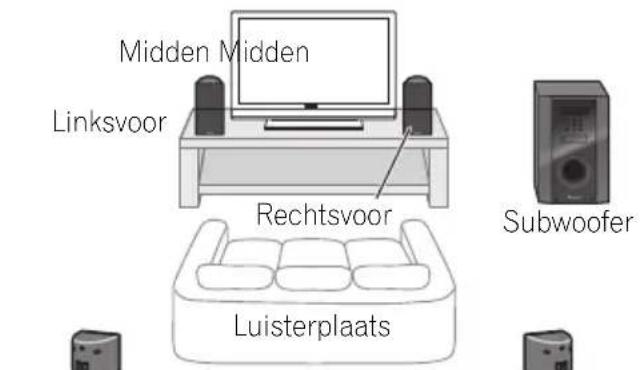
Surround links
Surroundrechts
Surround links: Blauw
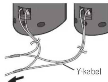
Naar de receiver-subwoofer
EASY M - Easy listening
Thomson 2003, 2017, 2060.
2064
Tokai 2083, 2091
Toshiba 2007, 2061, 2073.
- 2077
TRANScontinentns 2094
Trio 2093
TruVision 2090
Wharfedale 2085, 2086
Xbox 2003
Xlogic 2086, 2093
XMS 2093
Yamada 2094
Yamaha 2011
Yamakawa 2083, 2094
Yukai 2006, 2052
TV
Fabrikant Code
A.R. Systems 0040
Acme 0026
Acura 0027, 0039
ADC 0025
Admiral 0023,0024,0025, 0030,0031
Adyson 0026, 0113, 0114
Agashi 0113,0114
Agazi 0025
Aiko 0026,0027,0039, 0040,0113,0114
Aim 0040
Aiwa 0084
Akai 0027,0028,0034, 0037,0039,0040,0113, 0114
Akiba 0028, 0040
Akura 0025,0028,0039 0040
Alaron 0113
Alba 0010,0026,0027, 0028,0032,0035,0037, 0039,0040,0075,0078, 0088,0113
Alcyon 0017
Allorgan 0114
Allstar 0034,0040
AMOi 0109
Amplivision 0010,0026, 0041,0114
Amstrad 0025,0027,0028, 0039,0040
Anam 0027
Anglo 0027,0039
Anitech 0017.0025,0027, 0039,0040
Ansonic 0010,0018,0027, 0029,0039,0040
Arcam 0113, 0114
Arcam Delta 0026
Aristona 0034, 0037, 0040
Arthur Martin 0041
ASA 0023, 0031
Asberg 0017, 0034, 0040
Astra 0027
Asuka 0025,0026,0028, 0113,0114
Atlantic 0026,0034,0037 0040.0113
Atori 0027, 0039
Auchan 0041
Audiosonic 0010,0026, 0027,0028,0034,0037, 0040,0114
AudioTon 0010, 0026.0114
Ausind 0017
Autovox 0017, 0023, 0025, 0026, 0114
Awa 0113,0114
Baird 0114
Bang & Olufsen 0023, 0115
Basic Line 0027, 0028, 0034, 0039, 0040, 0114
Bastide 0026.0114
Baur 0037.0040
Bazin 0114
Beko 0010,0035,0040, 0060
Benq 0104
Beon 0034,0037,0040
Best 0010
Bestar 0010, 0034, 0040
Binatone 0026, 0114
Blue Sky 0028, 0040
Blue Star 0036
Boots 0026, 0114
BPL 0036,0040
Brandt 0033,0038,0042, 0044
Brinkmann 0040
Brionvega 0023,0034, 0037,0040
Britannia 0026, 0113, 0114
Bruns 0023
BTC 0028
Bush 0027,0028,0030 0032,0034,0036,0037 0039,0040,0065,0078 0114
Capsonic 0025
Carena 0040
Carrefour 0032
Cascade 0027, 0039, 0040
Casio 0106
Cathay 0034,0037,0040
CCE 0114
Centurion 0034,0037,0040
Century 0023
CGE 0010, 0017
Cimline 0027, 0039
City 0027, 0039
Clarivox 0037
Clatronic 0010,0017,0025, 0026,0027,0028,0034, 0035,0039,0040,0114
CMS 0113
CMS Hightec 0114
Concorde 0027,0039
Condor 0010, 0026, 0034, 0035, 0039, 0040, 0113
Contec 0026,0027,0032, 0039,0113
Continental Edison 0033
Cosmel 0027, 0039
Crosley 0017, 0023
Crown 0010,0017,0027, 0034,0035,0037,0039, 0040
CS Electronics 0026, 0028, 0113
CTC Clatronic 0029
Cybertron 0028
Daewoo 0013,0026,0027, 0034,0039,0040,0054, 0064,0091,0113,0114
Dainichi 0028, 0113
Dansai 0025,0034,0037 0040,0113,0114
Dantax 0010, 0037
Dawa 0040
Daytron 0027, 0039
De Graaf 0030
Decca 0026,0034.0037 0040.0114
Denver 0098, 0103
Desmet 0034,0037,0040
Diamant 0040
Diamond 0113
Dixi 0027,0034,0037,0039. 0040.0114
DTS 0027,0039
Dual 0026,0040,0114
Dual-Tec 0026, 0027
Dumont 0023,0026,0029 0114
Dux 0037
Dynatron 0034,0037,0040
Elbe 0010, 0018, 0040, 0114
Elcit 0023
Electa 0036
ELECTROTECH 0027
Elin 0026,0034,0037,0039, 0040.0113
Elite 0028,0034,0040
Elman 0029
Elta 0027, 0039, 0113
Emerson 0010, 0023, 0040
Epson 0101
Erres 0034, 0037, 0040
ESC 0114
Etron 0027
Eurofeel 0025, 0114
Euroline 0037
Euroman 0010,0025,0026, 0034.0040.0113.0114
Europhon 0026,0029, 0034.0040.0113.0114
Expert 0041
Exquisit 0040
Fenner 0027, 0039
Ferguson 0033,0037,0038, 0042
Fidelity 0026,0030,0040, 0113
Filsai 0114
Finlandia 0030
Finlux 0017,0023,0026, 0029,0034,0037,0040, 0114
Firstline 0026,0027,0034, 0039,0040,0113,0114
Fisher 0010, 0023, 0026, 0032, 0035, 0114
Flint 0034.0040
Formenti 0017,0023,0024, 0026,0037,0113
Formenti/Phoenix 0113
Fortress 0023.0024
Fraba 0010,0040
Friac 0010
Frontech 0025,0027,0030. 0031.0039.0114
Fujitsu 0114
Fujitsu General 0114
Funai 0025
Galaxy 0035, 0040
Galaxis 0010, 0040
GBC 0027, 0032, 0039
Geant Casino 0041
GEC0026,0031,0034,0037 0040,0114
Geloso 0027, 0030, 0039
General Technic 0027, 0039
Genexxa 0028,0031,0034, 0040
Giant 0114
GoldHand 0113
Goldline 0040
GoldStar 0010,0026,0027, 0030,0034,0037,0039, 0040,0113,0114
Goodmans 0025,0027, 0032,0034,0037,0039, 0040.0107.0114
Gorenje 0010, 0035
GPM 0028
Graetz 0031
Granada 0017,0026,0030, 0032,0034,0037,0040, 0041,0114
Grandin 0027,0028,0036 0037
Gronic 0114
Grundig 0009, 0010, 0017, 0040, 0047
Halifax 0025,0026,0113, 0114
Hampton 0026, 0113, 0114
Hanseatic 0010,0018, 0026,0027,0032,0034, 0037,0039,0040,0114
Hantarex 0027, 0039, 0040
Hantor 0040
Harwood 0039, 0040
HCM 0025,0026,0027, 0036,0039,0040,0114
Hema 0039, 0114
Higashi 0113
HiLine 0040
Hinari 0027,0028,0032 0034,0037,0039,0040
Hisawa 0028, 0036, 0041
Hitachi 0022,0026,0030, 0031,0032,0040,0076, 0111,0114
Hornyphon 0034, 0040
Hoshai 0028
Huanyu 0026, 0113
Hygashi 0026, 0113, 0114
Hyper 0026,0027,0039 0113.0114
Hypson 0025,0026,0034, 0036,0037,0040,0041, 0114
Iberia 0040
ICE 0025,0026,0027,0028, 0034,0039,0040,0113, 0114
ICeS 0113
Imperial 0010,0017,0031, 0034,0035,0040
Indiana 0034, 0037, 0040
Ingelen 0031
Ingersol 0027, 0039
Inno Hit 0017,0026,0027, 0028,0034,0037,0039, 0040,0114
Innovation 0025, 0027
Interactive 0010
Interbuy 0027, 0039
Interfunk 0010,0023,0031, 0034,0037,0040
International 0113
Intervention 0010,0025, 0026,0029,0040,0114
Irradio 0017,0027,0028, 0034,0037,0039,0040
Isukai 0028, 0040
ITC 0026,0114
ITS 0028,0034,0036,0040, 0113
ITT 0027,0031
ITV0027,0037,0040
JVC0019,0020,0032,0034 0077
Kaisui 0026, 0027, 0028, 0036, 0039, 0040, 0113, 0114
Kamosonic 0026
Kamp 0026, 0113
Kapsch 0031
Karcher 0010,0026,0027, 0037,0040
Kawasho 0113
Kendo 0010,0029,0030 0040
KIC 0114
Kingsley 0026, 0113
Kneissel 0010, 0018, 0040
Kolster 0034, 0040
Konka 0028
Nordmende 0023,0031, 0033.0034
Nordvision 0037
Novatronic 0040
Oceanic 0031, 0041
Okano 0010.0035.0040
ONCEAS 0026
Opera 0040
Orbit 0034, 0040
Orion 0027,0034,0037 0039,0040,0079
Online 0040
Osaki 0025, 0026, 0028, 0040, 0114
Oso 0028
Otto Versand 0024, 0026,0032,0034,0036, 0037,0040,0114
Pael 0026, 0113
Palladium 0010, 0026, 0035.0040.0114
Palsonic 0114
Panama 0025,0026,0027, 0039,0040,0113,0114
Panasonic 0008,0031, 0040,0043,0049,0099, 0102,0121
Panavision 0040
Pathe Cinema 0010, 0018, 0026, 0041, 0113
Pausa 0027, 0039
Perdio 0040, 0113
Perfekt 0040
Philco 0010, 0017, 0023, 0040
Philharmonic 0026, 0114
Philips 0000,0002,0023, 0026,0034,0037,0040, 0045,0048,0050,0055, 0056,0058,0059,0067, 0068,0080,0081,0087, 0090,0097,0100
Phoenix 0010,0023.0034. 0037.0040.0113
Phonola 0023,0034,0037 0040.0113
Pioneer 0010,0031,0033, 0034.0037,0040,0120
Plantron 0025,0034,0039, 0040
Playsonic 0114
Poppy 0027, 0039
Prandoni-Prince 0017, 0030
Precision 0026.0114
Prima 0027,0031,0039
Profex 0027, 0039
Profi-Tronic 0034,0040
Proline 0034, 0040
Prosonic 0010,0026,0037 0040,0113,0114
Protech 0025,0026,0027 0029,0034,0037,0114
Provision 0037, 0040
Pye 0034, 0037, 0040, 0083
Pymi 0027, 0039
Quandra Vision 0041
Quelle 0025,0026,0034, 0037,0040,0114
Questa 0032
Radialva 0040
Radio Shack 0040
Radiola 0034,0037,0040, 0114
Radiomarelli 0023, 0040
Radiotone 0010,0034, 0039,0040
Rank 0032
Recor 0040
Redstar 0040
Reflex 0040
Revox 0010,0034,0037 0040
Rex 0025, 0030, 0031
RFT 0010, 0018, 0023
Rhapsody 0113
R-Line 0034,0037,0040
Roadstar 0025,0027,0028 0039
Robotron 0023
Rowa 0113, 0114
Royal Lux 0010
RTF 0023
Saba 0023, 0031, 0033, 0038, 0042, 0044
Saisho 0025,0026,0027 0039,0114
Salora 0030, 0031
Sambers 0017, 0029
Samsung 0004,0005,0010
0025,0026,0027,0034
0035,0037,0039,0040
0062,0063,0066,0089
0093,0113,0114
Sandra 0026, 0113, 0114
Sansui 0034, 0040
Sanyo 0010,0018,0026, 0032,0039,0072,0113, 0114
SBR 0037,0040
SCHAUB LORENTZ 0031
Schneider 0026,0028, 0034,0037,0040,0075, 0114
SEG0025,0026,0029,0032 0037,0039,0040,0075 0113,0114
SEI 0040
SEI-Sinudyne 0023,0029, 0031
Seleco 0030, 0031, 0032
Sencora 0027, 0039
Sentra 0039
Serino 0113
Sharp 0015, 0016, 0024, 0032, 0069, 0092
Siarem 0023,0029,0040
Sierra 0034.0040
Siesta 0010
Silva 0113
Silver 0032
Singer 0023, 0029, 0041
Sinudyne 0023,0029,0037 0040
Skantic 0031
Solavox 0031
Sonitron 0010,0114
Sonoko 0025,0026,0027, 0034,0037,0039,0040, 0114
Sonolor 0031.0041
Sontec 0010,0034,0037 0040
Sony 0001,0003,0027, 0032,0046,0053,0057, 0070,0073,0082,0086, 0096,0110,0112
Sound & Vision 0028, 0029
Soundwave 0034,0037, 0040
Standard 0026,0027,0028, 0034,0039,0040,0114
Starlight 0037
Starlite 0039, 0040
Stenway 0036
Stern 0030, 0031
Strato 0039, 0040
Stylandia 0114
Sunkai 0027
Sunstar 0039.0040
Sunwood 0027, 0034, 0039, 0040
Superla 0026, 0113, 0114
SuperTech 0039,0040, 0113
Supra 0027, 0039
Susumu 0028
Sutron 0027, 0039
Sydney 0026, 0113, 0114
Sysline 0037
Sytong 0113
Tandy 0024,0026,0028, 0031,0114
Tashiko 0026,0030,0032 0113.0114
Tatung 0026,0034,0037 0040.0114
TCM 0025.0027
Teac 0040, 0114
Tec 0026, 0027, 0039, 0114
TEDELEX 0114
Teleavia 0033
Telecor 0040,0114
Telefunken 0033,0034, 0040.0042
Telegazi 0040
Telemeister 0040
Telesonic 0040
Telestar 0040
Teletech 0027,0037,0039, 0040
Teleton 0026, 0114
Televideon 0113
Televiso 0041
Tensai 0027,0028,0034, 0039,0040,0114
Tesmet 0034
Tevion 0025.0027
Texet 0026,0039,0113 0114
Thomson 0006,0007,0026, 0033,0034,0038,0040, 0042.0044.0095
Thorn 0037, 0040
Tokai 0034, 0040, 0114
Tokyo 0026, 0113
Tomashi 0036
Toshiba 0011, 0012, 0032, 0061, 0094, 0114
Towada 0031.0114
Trakton 0114
Trans Continens 0040, 0114
Transtec 0113
Trident 0114
Triumph 0040
Uher 0010,0017,0031, 0034.0040
Ultravox 0023, 0026, 0029, 0040, 0113
Unic Line 0040
United 0037
Universum 0010,0017, 0025,0034,0035,0037, 0040,0114
Univox 0040
Vestel 0030,0031,0034, 0035,0037,0040,0114
Vexa 0027,0037,0039, 0040
Victor 0032, 0034
VIDEOLOGIC 0113
Videologique 0026,0028. 0113.0114
VideoSystem 0034, 0040
Videotechnic 0113, 0114
Viewsonic 0108
Visiola 0026, 0113
Vision 0034, 0040, 0114
Vortec 0034,0037,0040
Voxson 0017, 0023, 0030, 0031, 0034, 0040
Waltham 0026, 0040, 0114
Watson 0034, 0037, 0040
Watt Radio 0026,0029, 0113
Wega 0023,0032,0040
Wegavox 0039
Weltblick 0034,0037.0040. 0114
White Westinghouse
0026,0029,0037,0040 0113
Xrypton 0040
Yamishi 0040, 0114
Yokan 0040
Yoko 0010,0025,0026, 0027,0028,0034,0037 0039,0040,0113,0114
Yorx 0028
Zanussi 0030, 0114
VCR
Fabrikant Code
Adyson 1017
Aiwa 1000, 1001, 1002
Akai 1001
Akiba 1007, 1017
Akura 1001, 1007, 1017
Alba 1002, 1003, 1004, 1007, 1017, 1018
Ambassador 1004
Amstrad 1000, 1017, 1018
Anitech 1007, 1017
ASA 1005, 1006
Asuka 1000, 1005, 1006, 1007, 1017
Audiosonic 1018
Baird 1000, 1001, 1003, 1018
Bang & Olufsen 1019
Basic Line 1002, 1003, 1004, 1007, 1017, 1018
Baur 1006
Bestar 1003, 1004, 1018
Black Panther Line 1003, 1018
Blaupunkt 1006
Bondstec 1004, 1017
Bush 1002, 1003, 1007, 1017, 1018
Cathay 1018
Catron 1004
CGE 1000, 1001
Cimline 1002, 1007, 1017
Clatronic 1004, 1017
Condor 1003, 1004, 1018
Crown 1003, 1004, 1007, 1017, 1018
Daewoo 1003, 1004, 1018
Dansai 1007, 1017, 1018
Dantax 1002
Daytron 1003, 1018
De Graaf 1006
Decca 1000, 1001, 1006
Denko 1017
Dual 1001, 1006, 1018
Dumont 1000, 1006
Elbe 1018
Elcatech 1017
Elsay 1017
Elta 1007, 1017, 1018
Emerson 1017
ESC 1003, 1018
Etzuko 1007, 1017
Ferguson 1001
Fidelity 1000, 1017
Finlandia 1006
Finlux 1000, 1001, 1006
Firstline 1002, 1005, 1007, 1017
Flint 1002
Formenti/Phoenix 1006
Frontech 1004
Fujitsu 1000
Funai 1000
Galaxy 1000
GBC 1004, 1007
GEC 1006
Geloso 1007
General 1004
General Technic 1002
GoldHand 1007, 1017
GoldStar 1000, 1005
Goodmans 1000, 1003, 1004, 1005, 1007, 1017, 1018
Graetz 1001
Granada 1006
Grandin 1000, 1003, 1004, 1005, 1007, 1017, 1018
Grundig 1006, 1007
Hanseatic 1005, 1006, 1018
Harwood 1017
HCM 1007, 1017
Hinari 1002, 1007, 1017, 1018
Hisawa 1002
Hitachi 1000, 1001, 1006, 1012
Hypson 1002, 1007, 1017, 1018
Impego 1004
Imperial 1000
Inno Hit 1003, 1004, 1006, 1007, 1017, 1018
Innovation 1002
Interbuy 1005, 1017
Interfunk 1006
Intervention 1000, 1018
Irradio 1005, 1007, 1017
ITT 1001
ITV 1003, 1005, 1018
JVC 1001, 1013
Kaisui 1007, 1017
Karcher 1006
Kendo 1002, 1003, 1004, 1017
Kenwood 1001
Korpel 1007, 1017
Kyoto 1017
Lenco 1003
Leyco 1007, 1017
LG 1000, 1005, 1016
Lifetec 1002
Loewe Opta 1005, 1006
Logik 1007, 1017
Lumatron 1003, 1018
Luxor 1017
M Electronic 1000
Manesth 1007, 1017
Marantz 1006
Mark 1018
Matsui 1002, 1005
Mediator 1006
Medion 1002
Memorex 1000, 1005
Memphis 1007, 1017
Micromaxx 1002
Microstar 1002
Migros 1000
Mitsubishi 1000, 1006
Multitech 1000, 1004, 1006, 1007, 1017
Murphy 1000
NEC 1001
Neckermann 1001, 1006
NEI 1006
Nesco 1007, 1017
Nikkai 1004, 1017, 1018
Nokia 1001, 1018
Nordmende 1001
Oceanic 1000, 1001
Okano 1002, 1017, 1018
Orion 1002
Orson 1000
Osaki 1000, 1005, 1007, 1017
Otto Versand 1006
Palladium 1001, 1005, 1007, 1017
Panasonic 1010
Pathe Marconi 1001
Perdio 1000
Philco 1017
Philips 1006, 1012, 1019
Phonola 1006
Pioneer 1006, 1120
Portland 1003, 1004, 1018
Prinz 1000
Profex 1007
Proline 1000
Prosonic 1002, 1018
Pye 1006
Quelle 1000, 1006
Radialva 1017
Radiola 1006
Rex 1001
RFT 1004, 1006, 1017
Roadstar 1003, 1005, 1007, 1017, 1018
Royal 1017
Saba 1001
Saisho 1002, 1007
Samsung 1008
Samurai 1004, 1017
Sansui 1001
Saville 1018
SBR 1006
Schaub Lorenz 1000, 1001
Schneider 1000, 1002, 1003, 1004, 1005, 1006, 1007, 1017, 1018
SEG 1007, 1017, 1018
SEI-Sinudyne 1006
Seleco 1001
Sentra 1004, 1017
Sentron 1007, 1017
Sharp 1009
Shintom 1007, 1017
Shivaki 1005
Siemens 1005
Silva 1005
Silver 1018
Sinudyne 1006
Solavox 1004
Sonneclair 1017
Sonoko 1003, 1018
Sontec 1005
Sony 1011
Standard 1003, 1018
Stern 1018
Sunkai 1002
Sunstar 1000
Suntronic 1000
Sunwood 1007, 1017
Symphonic 1017
Taisho 1002
Tandberg 1018
Tashiko 1000
Tatung 1000, 1001, 1006
TCM 1002
Teac 1018
Tec 1004, 1017, 1018
Teleavia 1001
Telefunken 1001
Teletech 1017, 1018
Tenosal 1007, 1017
Tensai 1000, 1005, 1007, 1017
Tevion 1002
Thomson 1001, 1015
Thorn 1001
Tokai 1005, 1007, 1017
Tonsai 1007
Toshiba 1001, 1006. 1014
Towada 1007, 1017
Towika 1007, 1017
TVA 1004
Uher 1005
Ultravox 1018
United Quick Star 1003, 1018
Universum 1000, 1005, 1006
Videon 1002
Weltblick 1005
Yamishi 1007, 1017
Yokan 1007, 1017
Yoko 1004, 1005, 1007, 1017
Hoofdstuk 10
SX-SWR2 receiver-subwoofer
- Audiogedeelte
Nominaal uitgangsvermogen Voor, midden, surround . . . 100 W per kanaal (1 kHz,4Ω,10%) Subwoofer . . . . . . 100 W (100 Hz,4Ω,10%)
FM-tunergedeelte
Published by Pioneer Corporation.
Copyright © 2010 Pioneer Corporation.
All rights reserved.
Publication de Pioneer Corporation.
© 2010 Pioneer Corporation.
PIONEER ELECTRONICS (USA) INC.
P.O. BOX 1540, Long Beach, California 90801-1540, U.S.A. TEL: (800) 421-1404
PIONEER ELECTRONICS OF CANADA, INC.
300 Allstate Parkway, Markham, Ontario L3R 0P2, Canada TEL: 1-877-283-5901, 905-479-4411
PIONEER EUROPE NV
Haven 1087, Keetberglaan 1, B-9120 Melsele, Belgium TEL: 03/570.05.11
PIONEER ELECTRONICS ASIACENTRE PTE. LTD.
253 Alexandra Road, #04-01, Singapore 159936 TEL: 65-6472-7555
PIONEER ELECTRONICS AUSTRALIA PTY. LTD.
5 Arco Lane, Heatherton, Victoria, 3202, Australia, TEL: (03) 9586-6300
PIONEER ELECTRONICS DE MEXICO S.A. DE C.V.
Blvd. Manuel Avila Camacho 138 10 piso Col.Lomas de Chapultepec, Mexico, D.F. 11000 TEL: 55-9178-4270 K002_B2_En