
RV 3 - Receiver MAGNAT - Free user manual and instructions
Find the device manual for free RV 3 MAGNAT in PDF.
| Product type | Integrated tube amplifier |
| Model | RV 3 |
| Brand | Magnat |
| Rated output power (20 Hz - 20 kHz, THD < 1%, 4 Ω) | 2 x 200 W |
| Pulse output power (1 kHz, 4 Ω) | 2 x 350 W |
| Frequency response | 5 Hz - 110 kHz (-3 dB); 20 Hz - 20 kHz (+/- 0.1 dB); Phono 20 Hz - 20 kHz (+/- 0.3 dB) |
| Subsonic filter | 16 Hz, 18 dB/octave |
| Signal-to-noise ratio | Not specified |
| Input sensitivity / impedance (CD/Tuner/Aux/Line/Tape) | 600 mV / 100 kΩ |
| Phono MM input sensitivity / impedance | 3 mV / 47 kΩ |
| Phono MC input sensitivity / impedance | 0.3 mV / 470 Ω |
| Audio inputs | Phono MC, Phono MM, CD, Tuner, Aux, Tape |
| Outputs | Preamp (PRE Out), Recording (REC Out), Speakers (2 pairs, bi-wiring possible), Headphones (6.3 mm jack) |
| Tube preamplifier | 2 x 12AU7 / ECC 82 |
| Recommended speaker impedance | 4 to 8 Ω |
| Power supply | 230 V AC / 50 Hz |
| Max power consumption | 350 W |
| Dimensions (W x H x D) of main unit | 434 x 155 x 410 mm (with controls and connectors) |
| Weight | 19.5 kg |
| Ambient operating temperature | 5 °C to 30 °C |
| Protection | Protection circuit against short circuit, overcurrent and DC offset |
| Included accessories | Instruction manual, remote control, batteries (2x AAA), power cable, screwdriver for remote control |
| Care and cleaning | Clean with a dry cloth only; do not use chemical products |
| Tube life expectancy | Approximately 20,000 to 50,000 hours |
Frequently Asked Questions - RV 3 MAGNAT
User questions about RV 3 MAGNAT
0 question about this device. Answer the ones you know or ask your own.
Ask a new question about this device
Download the instructions for your Receiver in PDF format for free! Find your manual RV 3 - MAGNAT and take your electronic device back in hand. On this page are published all the documents necessary for the use of your device. RV 3 by MAGNAT.
USER MANUAL RV 3 MAGNAT
natural_image
Close-up of a black electronic device with heat sinks and control knobs (no visible text or symbols)Important notes for installation / warranty card
natural_image
Illustration of five different household appliances or tools: a flat sheet, a handheld device, a pen, a cord with cable, and a rectangular object (no text or symbols visible)VOR INBETRIEBNAHME
natural_image
Pure electrical circuit lines without any symbols20 Hz - 20 kHz, THD < 1.0%, 8 Ohm 2 x 150 W
CD/Tuner/Aux/Line/Tape 110 dB (A)
Phono MM 90 dB (A)
Phono MC 78 dB (A)
9 Safety precautions
9 Instructions for disposal
10 Operational elements and connections
10 Front panel
10 Rear/connections
11 Remote control
11 Initial Operation
12 Tube replacement
12 Service and technical problems
12 Specifications
ACCESSORIES
1) Instruction manual
2) Remote control
3) Batteries for remote control (2x AAA)
4) Mains cable
5) Screwdriver for the remote control
natural_image
Illustration of five different electrical components: a flat plate, a variable resistor, a wire-wound tool, a screwdriver, and a battery (no text or symbols present)BEFORE STARTING
Dear customer,
Thank you for choosing the Magnat RV 3 valve amplifier.
Please read the following information carefully before starting to use the RV 3.
GB
IMPORTANT SAFETY PRECAUTIONS
- Please read the instruction manual carefully before use and keep it in a safe place.
- This device is only intended for use with 230 V/50 Hz AC voltage.
- Only operate the device at an ambient/room temperature between 5^ and 30^ .
- A valve amplifier generates a lot of waste heat. Make sure there is sufficient ventilation for the device. There must be a minimum gap of 10cm between objects to the side and to the rear. The area above the amplifier should be as free as possible, however there should be a clear gap of at least 30cm to other objects.
- Do not place any objects on top of the device (magazines, CD/record cases, etc.).
- Please do not position any sources of heat, such as radiators, ovens, naked flames or other devices that generate heat in close proximity to the device.
- The device and the remote control should not be exposed to dripping or splash water or high levels of humidity.
- No objects filled with liquids, such as vases, shall be places on the unit.
- In the event of contact with moisture or liquids remove the mains adapter immediately.
- Only clean the device using a dry cloth. Do not use any cleaning agents or chemical solvents when cleaning, as these could damage the surface of the device.
- The mains cable must always be operational. The device should not continue to be operated if there is visible damage to the mains cable. A damaged cable should not be repaired, but must be replaced.
- Do not connect or remove the mains cable with damp hands.
• Always refer to a qualified specialist for any maintenance or repair work. - If the device is not used, it should be switched off at the mains.
- Please remove the mains plug in the event of thunderstorms.
- Only connect the device using a 3-pin power cable with ground wire (earth)! This is part of the original accessories. Only use this original accessory for the power supply or a power cable that has been examined with regards to its safety (e.g. with a TÜV or VDE certificate).
- The safety function of the power cable's earthed plug should not be impaired in any way. The earthed plug has two contacts as well as a protective earth contact (i.e. a total of 3 contacts). The protective earth contact is important for operational safety and it must be in contact with the protective earth contact of the wall socket which supplies the device with electricity. If the earthed plug of the supplied power cable is not applicable with the socket (power supply) in your country, please refer to a qualified technician to exchange the cable.

This symbol warns the user that high voltage is used within the device which can result in electric shock.

This symbol makes the user aware that there are important notes in the enclosed instruction manual which must be observed.

WARNING:DO NOT OPEN! RISK OF ELECTRIC SHOCK! To reduce the risk of fire or electric shock, do not expose this unit to rain or moisture.
ATTENTION!
THE TUBES BECOME VERY HOT DURING OPERATION. BODILY CONTACT CAN RESULT IN BURNS.
INSTRUCTIONS FOR DISPOSAL
In accordance with European Directive 2002/96/EC all electrical and electronic appliances must be disposed of separately via local collection points. Please observe the local regulations and do not dispose of your old appliances with normal household waste.
Battery disposal
Old batteries are hazardous waste and must be disposed of in accordance with current regulations.

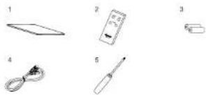
OPERATIONAL ELEMENTS AND CONNECTIONS - FRONT PANEL
1 Power
Switches the device on. The LED (2) illuminates green. If the device is switched off, it is completely disconnected from the mains supply. This switched off state means that the RV 3 does not consume any electricity at all.
3 Balance control
For adjusting the stereo balance between the speakers to the right or to the left.
4 Volume
For adjusting the overall volume of the music.
5 Input selector switch SOURCE
Switches between different audio sources:
- Phono MC: Record players with Moving Coil System (MC).
- Phono MM: Record players with a magnet system (MM) or MC system with high output level (high output MC).
- CD: CD player.
• Tuner: Radio reception device. - Aux: Other audio device (e.g. MP3 player).
- Tape: Tape or cassette recorder.
6 Display
The following information is indicated in the display:
• Heating phase of the tubes: WARM UP
- Selected audio input
PHONO MM - PHONO MC - TUNER -
CD - AUX - TAPE - LINE
• Increasing/decreasing volume
• Volume muting: MUTING
- Protect-Mode (in the event of malfunctions):
PROTECT
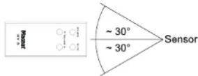
7 Infrared sensor
When using the remote control it must be aimed at this sensor.
8 Headphones
6.3 mm stereo output jack for headphones. The speakers are deactivated when this jack is used. Set the volume to a low level before connecting headphones.
OPERATIONAL ELEMENTS AND CONNECTIONS – REAR / CONNECTIONS
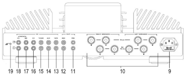
9 Mains connection
For connecting the supplied mains cable. The safety fuse should only be changed by qualified service personnel.
10 Speaker terminals
For the connection of stereo speakers with an impedance rating of 4-8 ohms (the correct polarity must be taken into account). (See also page 11.)
ANALOGUE RCA CONNECTIONS
For connecting analogue audio devices. Please observe the coloured marking of the sockets and connectors. Red is always the right channel.
11 PRE Out
Preamplifier output for connecting an external power amplifier or a powered subwoofer. The output level depends on the position of the volume knob.
12 REC Out
For connecting devices for analogue sound recording (e.g. tape recorder). The signal for the selected audio source with
fixed level applies for this output, i.e. it is independent of the position of the volume knob.
13 TAPE input
For the connection of a cassette deck or tape recorder.
14 AUX input
Connection of another audio source (e.g. MP3 or Minidisc player).
15 TUNER input
Connection of a radio reception device.
16 CD input
Connection of a CD player.
17 PHONO MM input
Connection of a record player with a magnet system (MM) or MC system with high output level (high output MC).
18 PHONO MC input
Connection of a record player with Moving Coil System (MC).
19 PHONO earth connection
Connection of the phono cable's earth wire in order to prevent humming.

OPERATIONAL ELEMENTS AND CONNECTIONS – REMOTE CONTROL
- Before using the remote control you will need to insert the supplied batteries (accessory No. 3):
- Use the supplied screwdriver (accessory No. 5) to remove the rear of the remote control.
- Insert the batteries into the battery compartment. When doing this pay attention to the correct polarity of the batteries.
- Replace the rear and tighten the screws.
- If the batteries have run out after prolonged use, please replace them (type AAA).
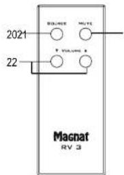
20 Source
This button enables direct selection of the individual audio inputs. The active input is indicated in the display.
21 Mute
You can mute the sound using this button. The sound can be reactivated by pressing this button again.
22 Volume
Increases (▲) or decreases (▼) the volume.
INITIAL OPERATION
- Place the RV 3 on an even surface. Observe the relevant clearance gaps as specified under "Important safety instructions".
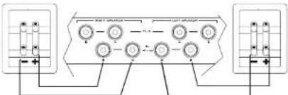
IMPORTANT: Do not place any objects on top of the device (magazines, CD/record cases, etc.). - Connect your speakers:
Single Wiring:
The stereo speakers (impedance of 4 to 8 ohms) are connected to the rear as follows:
flowchart
graph TD
    A["Terminal 1"] --> B["Component 1"]
    C["Terminal 2"] --> D["Component 2"]
    B --> E["Output"]
    D --> E
    style A fill:#f9f,stroke:#333
    style C fill:#f9f,stroke:#333
Only use high-quality audio speaker cables with a conductor cross section of min. 1.5 - 2.5 mm². Strip approx. 10 mm from the cables and twist the ends. Loosen the terminal screws one after the other and insert the stripped ends into the holes. Re-tighten the terminal screws. Make sure you pay attention to the correct polarity.
You can also use prefabricated cables with 4mm banana plugs or forked fittings.
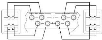
Bi Wiring:
The RV 3 offers the opportunity to operate speakers in a bi-wiring mode by using a second terminal pair. This means that the woofer and tweeter elements of the speaker are connected to the amplifier with separate cables.
flowchart
graph TD
    A["Input"] --> B["Component 1"]
    B --> C["Component 2"]
    C --> D["Output"]
    style A fill:#f9f,stroke:#333
    style B fill:#ccf,stroke:#333
    style C fill:#cfc,stroke:#333
    style D fill:#fcc,stroke:#333
Also observe the operating instructions for the speakers you are using.
- Connect your audio sources to the analogue connections.
- Connect the supplied mains cable to the rear and then insert the other end into a 230V socket.
- Turn the volume knob to the left to a low volume setting.
- Switch on the RV 3 using the power button on the front panel.
- When the tubes have heated up the device is ready for use.
- Select your desired audio source using the input selector switch.
PROTECTIVE CIRCUIT
To ensure maximum protection for the amplifier and the connected speakers the RV 3 is equipped with a protective circuit. In the event of a short circuit, overcurrent or DC offset it separates the speaker outputs from the amplifier. In this case "PROTECT" is indicated in the display. The device must be disconnected from the power supply and the cause of the malfunction determined. Start by checking the wiring of the speakers. If the malfunction occurs again, please contact a specialist and get the amplifier and/or the speakers checked.

TUBE REPLACEMENT
The device has a high quality preamplifier stage which is equipped with two tubes. The tubes have a very long service life when used under normal operating conditions (min. 20,000-50,000 hours). If it is necessary to replace the tubes, please refer to a specialist dealer.
SERVICE AND TECHNICAL PROBLEMS
If you should encounter any technical problems, please contact your specialist dealer or Magnat Audio-Produkte GmbH, Tel.: 02234807-0.
SPECIFICATIONS
Amplifier:
Power output:
Rated power 20 Hz – 20 kHz, THD < 1.0%, 4 Ohm 2 x 200 W 20 Hz – 20 kHz, THD < 1.0%, 8 Ohm 2 x 150 W Peak power 1 kHz, 4 Ohm 2 x 350 W
Frequency response :
CD/Tuner/Aux/Line/Tape 5 Hz - 110 kHz (-3 dB)
20 Hz - 20 kHz (+/- 0.1 dB)
Phono 20 Hz - 20 kHz (+/- 0.2 dB)
Subsonic filter: 16 Hz, 18 dB/octave
Signal to noise ratio:
CD/Tuner/Aux/Line/Tape 110 dB (A)
Phono MM 90 dB (A)
Phone MC 78 dB (A)
Input sensitivity/impedance:
CD/Tuner/Aux/Line/Tape 600 mV / 100 kOhm
Phono MM 3 mV / 47 kOhm
Phone MC 0.3 mV / 470 Ohm
Fitted with:
Preamplifier: 2 x 12AU7 / ECC 82
Dimensions (wxhxd):
Main device: 434 x 155 x 360 mm
Main device incl. operational elements/connecting terminals: 434 x 155 x 410 mm
Remote Control: 40 x 100 x 16 mm
Weight: 19.5 kg
Miscellaneous
Mains voltage: 230 VAC / 50 Hz
Electricity consumption: Max. 350 W
Subject to technical change.
For further information please visit our website: http://www.magnat.de.

SOMMAIRE
13 Accessoires
natural_image
Illustration of five different electronic components: a flat panel, a handheld device with a cable, a variable resistor, and a pen (no text or symbols present)AVANT LA MISE EN MARCHE
Cher client,
INSTRUCTIONS POUR LA MISE AU REBUT
PRISES CINCH ANALOGIQUES
flowchart
graph TD
    A["Input Unit 1"] --> B["Process Unit 1"]
    B --> C["Output Unit 2"]
    C --> D["Feedback Loop"]
    D --> E["Output Unit 3"]
    E --> F["Output Unit 4"]
    F --> G["Feedback Loop"]
    G --> H["Output Unit 5"]
    H --> I["Output Unit 6"]
    I --> J["Feedback Loop"]
    J --> K["Output Unit 7"]
    K --> L["Output Unit 8"]
    L --> M["Feedback Loop"]
    M --> N["Output Unit 9"]
    N --> O["Output Unit 10"]
    O --> P["Feedback Loop"]
    P --> Q["Output Unit 11"]
    Q --> R["Output Unit 12"]
    R --> S["Feedback Loop"]
    S --> T["Output Unit 13"]
    T --> U["Output Unit 14"]
    U --> V["Feedback Loop"]
    V --> W["Output Unit 15"]
    W --> X["Output Unit 16"]
    X --> Y["Feedback Loop"]
    Y --> Z["Output Unit 17"]
    Z --> AA["Output Unit 18"]
    AA --> AB["Feedback Loop"]
    AB --> AC["Output Unit 19"]
    AC --> AD["Output Unit 20"]
REMPLACEMENT DES TUBES
20 Hz - 20 kHz, THD < 1.0%, 8 Ohm 2 x 150 W
CD/Tuner/Aux/Line/Tape 110 dB (A)
Phono MM 90 dB (A)
Phone MC 78 dB (A)
natural_image
Five labeled diagrams of household appliances: flatboard, remote control panel, cord, screwdriver, and bulb (no text or symbols)ATTACCHI ANALOGICI CINCH
natural_image
Pure electrical circuit lines without any symbolsCD/Tuner/Aux/Line/Tape 110 dB (A)
Phono MM 90 dB (A)
Phone MC 78 dB (A)
natural_image
Illustration of five different household appliances: flatboard, remote control, screwdriver, and pen (no text or symbols)ANTES DE EMPEZAR
Estimado cliente,
natural_image
Pure electrical circuit lines without any symbols20 Hz - 20 kHz, THD < 1.0%, 4 Ohmios 2 x 200 W
20 Hz - 20 kHz, THD < 1.0%, 8 Ohmios 2 x 150 W
Potencia de pico 1 kHz, 4 Ohmios 2 x 350 W
CD/Tuner/Aux/Line/Tape 110 dB (A)
Phono MM 90 dB (A)
Phone MC 78 dB (A)
natural_image
Pure electrical circuit lines without any symbolsCongratulations! You have made a wise selection in becoming the owner of a MAGNAT HiFi equipment.
The equipments are checked and tested continuously during the entire production process. In case you have problems CNAT HIFI equipment, kindly observe the following:
-
The warranty period commences with the purchase of the component and is applicable only to the original owner.
-
During the warranty period we will rectify any defects due to faulty material or workmanship by replacing or repairing the defective part at our discretion. Further claims, and in particular those for price reduction, cancellation of sale, compensation for damages or subsequential damages, are excluded. The warranty period is not altered by the fact that we have carried out warranty work.
-
Unauthorized tampering with the equipment will invalidate this warranty.
-
Convuls have authorized double-point University price is needed. Chaul
-
Consult your authorized dealer first, if warranty service is needed. Should it prove necessary to return the component to the factory, please insure that the component is packed in original factory packing in good condition the quality control card has been filled out and enclosed with the component your enclose your receipt as proof of purchase.
-
Excluded from the warranty are: "Illuminales - Valves - Batteries - Wear parts - Shipping damages, either readily apparent or conceived (claims for such damages must be logged immediately with forwarding agent, the railway express office or post office); Scratches in cases, metal components, front panels, etc. (You must notify your dealer directly of such defects within three days of purchase.) - Defects caused by incorrect installation or connection, by operation errors (see operating instructions), by overhead handling and/or disassembly of existing requirements which have been repaired incorrectly or modified or where the case has been opened by persons other than us. - Consequential damages to other equipments. - Reimbursement of costs, without our prior consent, when repairing damages by third parties.

Toutes nos félicitations!
Name and address of the dealer/stamp
Käufer/Customer
Name/Name
Straße/Street
PLZ, Ort/City
Land/Country
Kaufdatum/buying date
No warranty without receipt!