AVICF9880BT - GPS Navigation System PIONEER - Free user manual and instructions
Find the device manual for free AVICF9880BT PIONEER in PDF.

User questions about AVICF9880BT PIONEER
0 question about this device. Answer the ones you know or ask your own.
Ask a new question about this device
Download the instructions for your GPS Navigation System in PDF format for free! Find your manual AVICF9880BT - PIONEER and take your electronic device back in hand. On this page are published all the documents necessary for the use of your device. AVICF9880BT by PIONEER.
USER MANUAL AVICF9880BT PIONEER
Precautionsbeforeconnectingthesystem5
Beforeinstallingthisproduct5
Toppreventdamage6
-Noticefortheblue/whitelead6
Partssupplied7
Connectingthepowercord(1)8
Connectingthepowercord(2)10
Connectingthesystem12
Connectingoseparatelysoldpower amp13
ConnectinganiPod/iPhoneoranAndroid device14
AttachingidentificationlabelstoUSB cables15
ConnectinganiPhonewithLightning connector15
-ConnectingviatheUSBport (iPhone)15
-ConnectingviatheHDMIport (iPhone)16
-ConnectingviatheRGBinput (iPhone)16
ConnectinganiPhonewith30-pin connector17
-ConnectingviatheAUXinput (iPhone)17
-ConnectingviatheRGBinput (iPhone)18
ConnectingtheAndroid device18
-ConnectingviatheHDMIport(Android device)18
-ConnectingviatheMHLport(Android device)19
ConnectingviatheUSBport(Android device)19
SecuringtheHighSpeedHDMI Cable20
Connectingarearviewcamera20
Connectingtheexternalvideo component21
-UsingAVinput21
-UsinganAUXinput22
ConnectinganHDMIdevice23
Connectingthereardisplay24
-Whenusingareardisplayconnectedto
rearvideooutput24

Installation
Precautionsbeforeinstallation25
Toavoidelectromagneticinterference25
Beforeinstalling25
-ForAVIC-F88DABandAVIC-F80DAB users26
Installingthisproduct26
-Installationwiththeholder27
-Installationusingthescrewholeson thesideofthisproduct28
InstallingtheGPSaerial29
-Wheninstallingtheaerialinsidethe vehicle(onthedashboardorrear shelf)30
Installingthemicrophone31
-Partssupplied31
-Mountingonthesunvisor31
-Installationonthesteeringcolumn32
-Adjustingthemicrophoneangle32

Afterinstallation
Afterinstallingthisproduct33
Yournewproductandthis manual
- Thenavigationfeaturesofthisproduct (andtherearviewcameraoptionifpurchased)areintendedsolelytoaidyouin theoperationofyourvehicle.Itisnotasubstituteforyourattentiveness,judgement andcarewhendriving.
- Neverusethisproducttoroutetohospitals,policestations,orsimilarfacilitiesinanemergency.Pleasecalltheappropriateemergencynumber.
- Donotoperatethisproduct,anyapplications,orthearviewcameraoption(ifpurchased)ifdoingssowilddivertyourattentioninanywayfromthesafeoperationofyourvehicle.Alwaysobservafedrivingsrulesandfollowallexistingtrafficregulations.Ifyouexperienceddifficultyinoperatingthisproductorreadingthedisplay,parkyourvehicleinasafelocationandapplythehandbrakebeforemakingthenecessaryadjustments.
- This manualexplainshowtoinstallthis productinyourvehicle. Operationofthis productisexplainedintheseparatemuals.
- Donotinstallthisproductwhereitmay(i) obstructthedriver'svision,(ii)impairthe performanceofanyofthevehicle'soperatingsystemsof)safetyfeatures,including airbags,hazardlampbuttons,or(iii)impair thedriver'sabilitytosafelyoperatorethevehicle.Insomecases,itmaynotbepossible toinstallthisproductbecauseofthevehicletypeortheshapeofthevehicleinterior.
- Modeliconsshowninthismanualindicate thatthedescriptionisintendedforthemodelsindicatedbytheicons. Ifthefollowingiconisshown,thedescrip-tionisappliedonlytothemodelshown.e.g.)
F88DAB
Thegraphicalsymbolplaceon theproductmeansdirectcurrent.
Important safeguards
4WARNING
Pioneerdoesn'trecommendthatyouinstall thisproductyourself.Thisproductdesignedforprofessionalinstallationonly.We recommendthatonlyauthorisedPioneerservicepersonnel,whohavespecialtraining andexperienceinmobileelectronics,setup andinstallthisproduct.NEVERSERVICE THISPRODUCTYOURSELF.Installingor servicingthisproductanditsconnecting cablesmayexposeoutotheriskofelectric shockorotherhazards,andcausedamagetothisproductthatisnotcoveredby warranty.
- Readthismanuallyandcarefullybefore installing this product.
- Keepthismanualhandyforfuturereference.
- Paycloseattentionontoall warningsinthis manualandfollowtheinstructionscarefully.
- Thisproductmayincertaintcircumstances displayinaccuratepositionofyourvehicle, thedistanceofobjectsshownonthe screen,andcompassdirections.Inaddition,thesystemhascertainlimitations,includingtheinabilitytoidifyone-way streets,temporarytrafficrestrictionsand potentiallyunsafedrivingsareas.Pleaseexerciseyourownjudgementinthelightof actualdrivingconditions.
- Aswithanyaccessoryinyourvehicle'sinterior, thisproductshouldnotdivertyourattentionfromthesafeoperationofyourvehicleasitmayresultinseriousinjuryordethatyouexperienceddifficultyinoperatingthesystemorreadingthedisplay,pleasemakeadjustmentswhilesafelyparked.
- Pleaseremembertowearyourseatbeltat alltimeswhileoperatingyourvehicle.If youareinanaccident,yourinjuriescan be considerablymoreseverifyourseatbelt isnotproperlyfastened.
01 (Precautions
- Certain country and government laws may prohibit or restrict the placement and use of this product in your vehicle. Please comply with all applicable laws and regulations regarding the use, installation and operation of this product.
Precautionsbefore connectingthesystem

WARNING
Donottakeanystepstotamperwithordis- ablethehandbrakeinterlocksystemwhich isinplaceforyourprotection.Tampering withordisablingthehandbrakeinterlock systemcouldresultinseriousinjuryor death.

CAUTION
- Ifyoudecidetoperformtheinstallation yourself,andhavespecialtrainingandexperienceinthemobileelectronicsinstallations,pleasecarefullyfollowallofthestepsintheinstallationmanual.
- Secureallwiringwithcableclampsorelectricaltape.Donotallowanybarewiringtoremainexposed.
- Donotdirectlyconnecttheyellowleadof thisproducttothevehiclebattery. If the leadisdirectlyconnectedtothebattery, enginevibrationmayeventuallycause theinsulationofailatthepointwhere theywirepassesfromthepassengercompartmentintotheenginecompartment.If theyellowlead'sinsulationtearsasresultofcontactwithmetalparts,short-circuitingcanoccur,resultingin considerabledanger.
- Itisextremelydangeroustoallowcables tobecomewoundaroundthesteeringcolumngearstick.Besuretoinstallthis product,itscables,andwiringawayinsuchsothattheywillnotobstructorhinderdriving.
- Makesurethatthecablesandwireswill notinterferewithorbecomecaughtin anyofthevehicle'smovingparts,especiallythesteeringwheel,gearstick,handbrake,slidingseatacks,doors,oranyof thevehicle'scontrols.
- Donotrouwireswheretheywillbeexposedtohightemperatures.Iftheinsulationheatsup, wiresmaybecome
damaged, resulting in short circuitors malfunction and permanent damaget to the product.
- DonotcuttheGPSaerialcabletoshorten itoruseanextensionomakeitlonger. Alteringtheaerialcablecouldresultina shortcircutormalfunction.
- Donotshortenanyleads.Ifyoudo,the protectioncircuit(fuseholder,fuseresistororfilter,etc.)mayfailtoworkproperly.
- Neverfeedpowertootherelectronic productsbycuttingtheinsulationof the powersupplyleadofthisproductandtappingintothelead.Thecurrentcapacity of theleadwillbeexceeded,causingoverheating.
Beforeinstallingthisproduct
- Usethisproductwitha12-voltbattery and negativeearthingonly. Failure to dosomay resultinafireormalfunction.
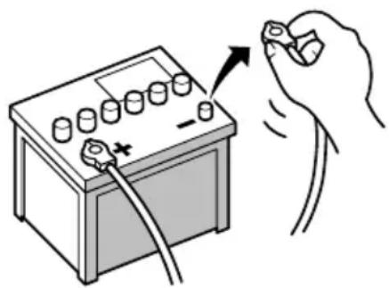
- Toavoidshortsintheelectricalsystem, be suretodisconnectthe(-)batterycablebeforeinstallation.

Topreventdamage

WARNING
- Usespeakersover50W(maximuminput power)andbetween4Ωto8Ω(impedancevalue).Donotuse1Ωto3Ωspeakersforthisproduct.
Theblackleadisearth.Pleaseearththis leadseparatelyfromtheearthhofhigh-currentproductssuchaspoweramps.Donot earthmorethanoneproducttogether withtheearthfromanotherproduct.For example,youmustseparatelyearthyany ampunitawayfromtheearthhofthisproduct.Connectionearthstogatheringcan causeafireand/ordamagetheproductsif theirearthsbecamedetached. -
Whenreplacingthefuse,besuretoonly useafuseoftheratingprescribedonthis product.
-
Whendisconnectingaconnector, pull the connectoritself.Donotpullthelead, as youmaypullitoutoftheconnector.
- ThisproductcannotbeinstalledinvehiclewithoutACC(accessory)positionontheignitionswitch.

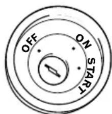
ACCpositionNoACCposition
- Toavoid short-circuiting, cover the disconnected lead with insulating tape. It is especially important to isolate all unused speaker leads, which if left uncovered may cause short circuit.
- Attachtheconnectorsoftthesamecolour tothecorrespondingcolouredport,i.e., blueconnectortotheblueport,blackto black,etc.
-
Refertotheowner's manualfordetailson connectingthepowerampandotherunits, thenmakeconnectionsaccordingly.
-
SinceauniqueBPTLCircuitisemployed, donotdirectlyearththe sideofthespeakerleadorconnectthe sideofan-othersideofthespeakerleadtogether.Be suretoconnectthe sideofthespeaker leadtothe sideofthespeakerleadon thisproduct.
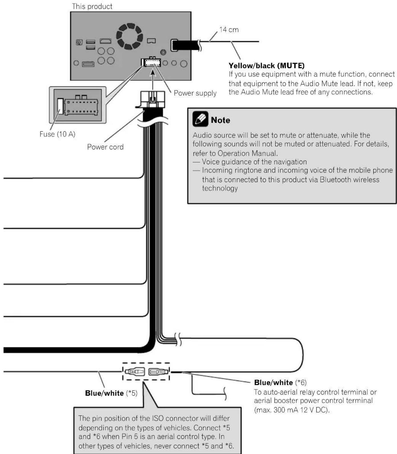
Noticefortheblue/whitelead

Important
Whenthisproductisin"PowerOFF"mode,the controlsignalisalsoturnedoff.If"PowerOFF"modeiscancelled,thecontrolsignalisoutput againandtheaerialisextendedwiththautoaerialfunction(iftheaerialisbeingused).Becareful sothatthextendederaialdoesnotcomeinto contactwithanyobstacles.
- Whentheignitionswitchisturnedon(ACC ON), a controlsignalisoutputthre blue/whitelead. Connecttoanexternal poweramp'systemremotecontrolterminal, the auto-aerial relay control terminal, or the aerial boosterpowercontrol terminal (max.300mA12VDC). The controlsignal is outputthre blue/whitelead, even if the audio source isswitchedoff.
- Besurenottousethisleadasthepower supplyleadfortheexternalpowerrms. Suchconnectioncouldcauseexcessive currentdrainandmalfunction.
- Besurenottousethisleadasthepower supplyleadfortheauto-aerialoraerial booster.Suchconnectioncouldcauseexcessivecurrentdrainandmalfunction.
Connection
Partssupplied
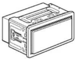
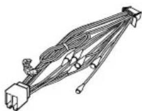
ThisproductPowercord
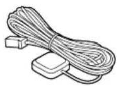
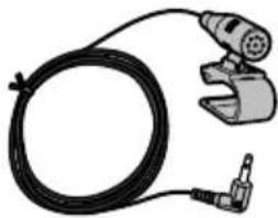
GPSaerialMicrophone
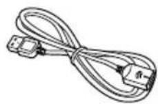
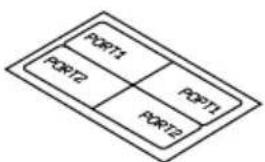
USBcableidentificationlabels
USBcable (2pcs.)
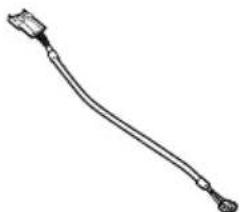

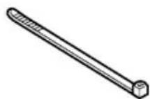
Locktie1VehicleBusconversion cable2
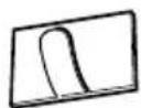

MetalsheetClamp(3pcs.)
Double-sidedtape

Notes
(^1) ThesepartsaresuppliedwithAVICF88DAB.
(^2) ThesepartsaresuppliedwithAVICF88DAB,AVIC-F80DABandAVICF980DAB.
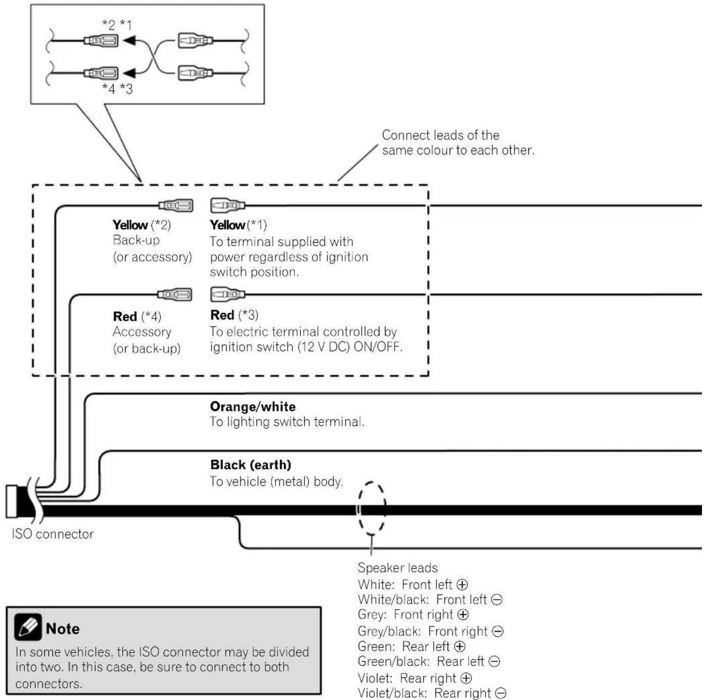
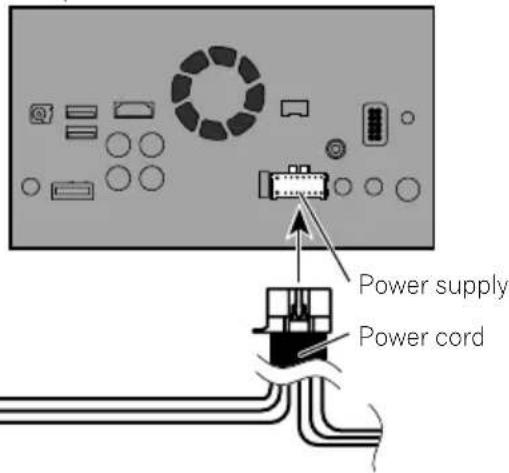
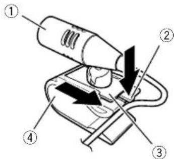
Connectingthepowercord(1)

Note
Depending on the types of vehicles, the function of 2 and 4 may be different. In this case, be sure to connect 1 to 4 and 3 to 2 as shown in the figure.
Connection

Connectingthepowercord(2)

Pink (CAR SPEED SIGNAL INPUT)
This product is connected here to detect the distance the vehicle travels. Always connect the vehicle's speed detection circuit. Failure to make this connection will increase errors in the vehicle's location display.

WARNING
IMPROPER CONNECTION MAY RESULT IN SERIOUS DAMAGE OR INJURY INCLUDING ELECTRICAL SHOCK, AND INTERFERENCE WITH THE OPERATION OF THE VEHICLE'S ANTILOCK BRAKING SYSTEM, AUTOMATIC GEARBOX AND SPEEDOMETER INDICATION.

CAUTION
It is strongly suggested that the speed pulse wire be connected for accuracy of navigation and better performance.

Note
The position of the speed detection circuit and the position of the handbrake switch vary depending on the vehicle model. For details, consult your authorised Pioneer dealer or an installation professional.
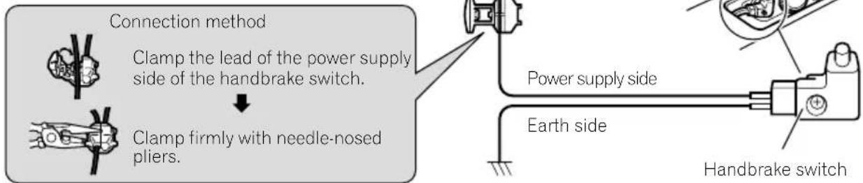
Light green (PARKING BRAKE)
Used to detect the ON/OFF status of the handbrake. This lead must be connected to the power supply side of the handbrake switch.
If this connection is made incorrectly or omitted, certain functions of this product will be unusable.

WARNING
LIGHT GREEN LEAD AT POWER CONNECTOR IS DESIGNED TO DETECT PARKED STATUS AND MUST BE CONNECTED TO THE POWER SUPPLY SIDE OF THE HANDBRAKE SWITCH. IMPROPER CONNECTION OR USE OF THIS LEAD MAY VIOLATE APPLICABLE LAW AND MAY RESULT IN SERIOUS INJURY OR DAMAGE.
Connection
This product
Violet/white (REVERSE-GEAR SIGNAL INPUT)
This is connected so that this product can detect whether the vehicle is moving forwards or backwards. Connect the violet/white lead to the lead whose voltage changes when the reverse gear is engaged. Unless connected, the sensor may not detect your vehicle travelling forward/backward properly, and thus the position of your vehicle detected by the sensor may be misaligned from the actual position.

Note
When you use a rear view camera, please make sure to connect this lead. Otherwise you cannot switch to the rear view camera picture.

Connectingthesystem

WARNING
- To avoid the risk of accident and the potential violation of applicable laws, this product should never be used while the vehicle is being driven except for navigation purposes. And, also rear displays should not be in a location where it is a visible distraction to the driver.
- In some countries, the viewing of images on a display inside a vehicle even by persons other than the driver may be illegal. Where such regulations apply they must be obeyed and this product's video source should not be used.

Connectingoseparatelysoldpoweramp
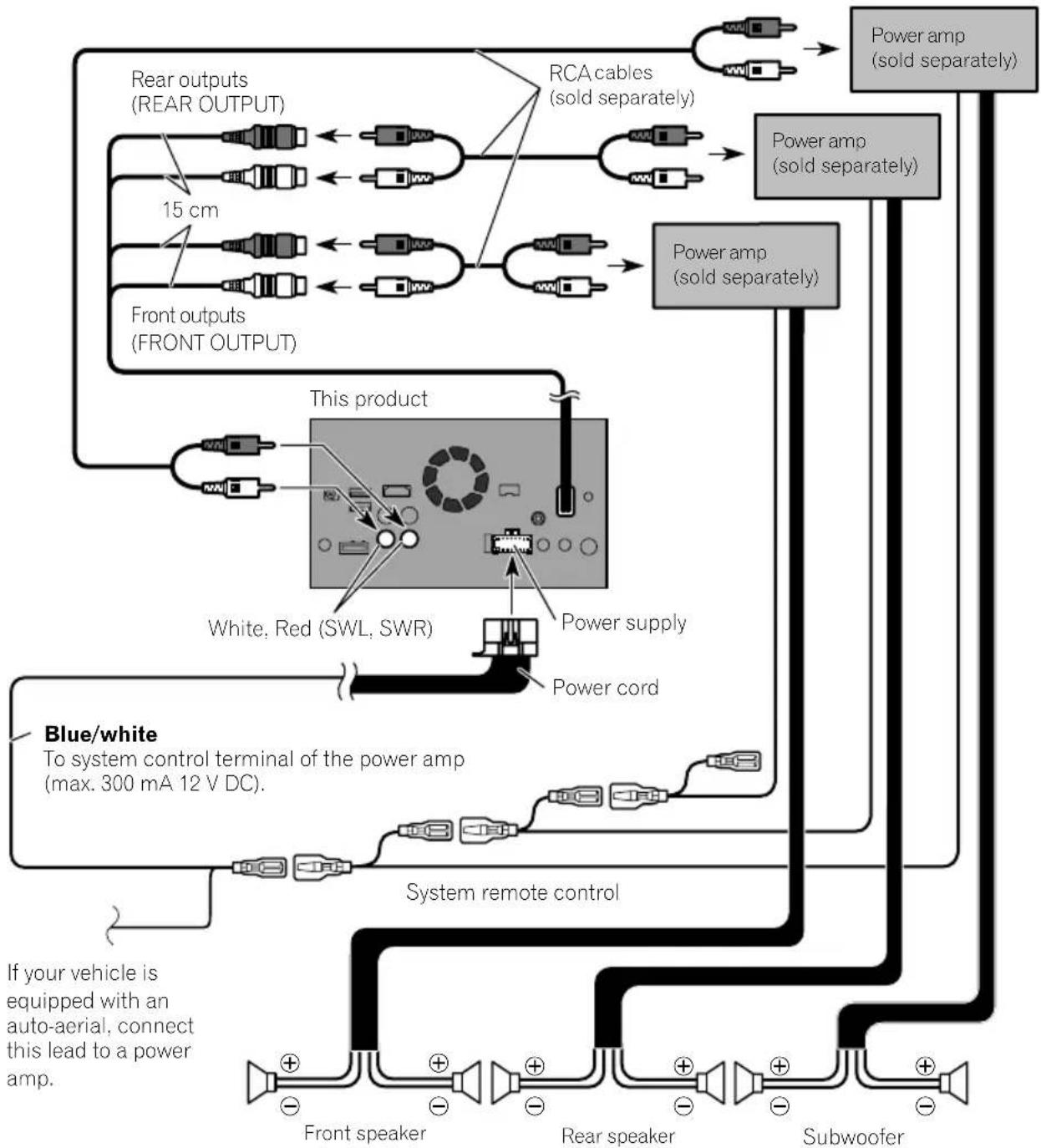

Notes
- You can change the RCA output of the subwoofer depending on your subwoofer system. (Refer to Operation Manual.)
- The subwoofer output of this product is monaural.

ConnectinganiPod/iPhoneorangAndroiddevice
Findourdeviceandthefunctionyouwanttooperatefromthelistbelow,andrefertothepagefortheconnection.
Dependingonthedevic,somefunctionsmaynotbeavailable.
| iPhone(5,5c,5s,6,6Plus)/iPodtouch(5thgeneration) | |
| iPod.audio | |
| AppleCarPlay | RefertoConnectingviatheUSBport(iPhone)onpage15. |
| AVICSYNCApp | |
| AppRadioMode | F88DAB |
| RefertoConnectingviatheHDMIport(iPhone)onpage16. | |
| AVICSYNCApp | F80DABf 980DAB F980BT F9880DAB F9880BT |
| RefertoConnectingviatheRGBinput(iPhone)onpage16. | |
| iPhone3GS/iPodtouch(2nd,3rdgeneration)/iPodclassic(80GB,160GB)/iPodnano(3rd,4th,5th,6th generation) | |
| iPod.audio | RefertoConnectingviatheAUXinput(iPhone)onpage17. |
| iPod(video) | |
| iPhone(4,4s)/iPodtouch(4thgeneration) | |
| iPod.audio | |
| iPod(video) | RefertoConnectingviatheRGBinput(iPhone)onpage18. |
| AppRadioMode | |
| AVICSYNCApp | |
| iPodnano(7thgeneration) | |
| iPod (audio) | Refer to Connecting via the USB port (iPhone) on page 15. |
| Androiddevice | |
| F88DAB | HDMIport |
| AppRadioMode | RefertoConnectingviatheHDMIport(Androiddevice)onpage18. |
| AVICSYNCApp | MHLport |
| RefertoConnectingviatheMHLport(Androiddevice)onpage19. | |
| F88DAB F80DAB | |
| AndroidAuto | RefertoConnectingviatheUSBport(Androiddevice)onpage19. |
| AVICSYNCApp | |

Attachingidentification labelstoUSBcables
AttachidentificationlabelstoUSBcablesbeforeinstallingthisproductinvehicle.
1ConnectUSBcablestotheUSBport1 and2ontherearofthisproduct.
2AttachtheidentificationlabelscorrespondingtoeachporttotheUSBcablesas illustratedbelow.
Attachthe"PORT1"labeltotheUSBcable connectedtotheUSBport1.
Attachthe"PORT2"labeltotheUSBcable connectedtotheUSBport2.

ConnectinganiPhonewith Lightningconnector

- Fordetailsonhowtoconnectanexternal deviceusingaseparatelysoldcable,refertothe manualforthecable.
- Fordetailsconcerningtheconnection, operationsandcompatibilityofiPhone,refertoOperationManual.
ConnectingviatheUSBport (iPhone)
TheUSBInterfacecableforiPod/iPhone(CD-IU52)(soldseparately)isrequiredforthecom- nnection.
- When using Apple CarPlay, connect the iPhone to USB port1.
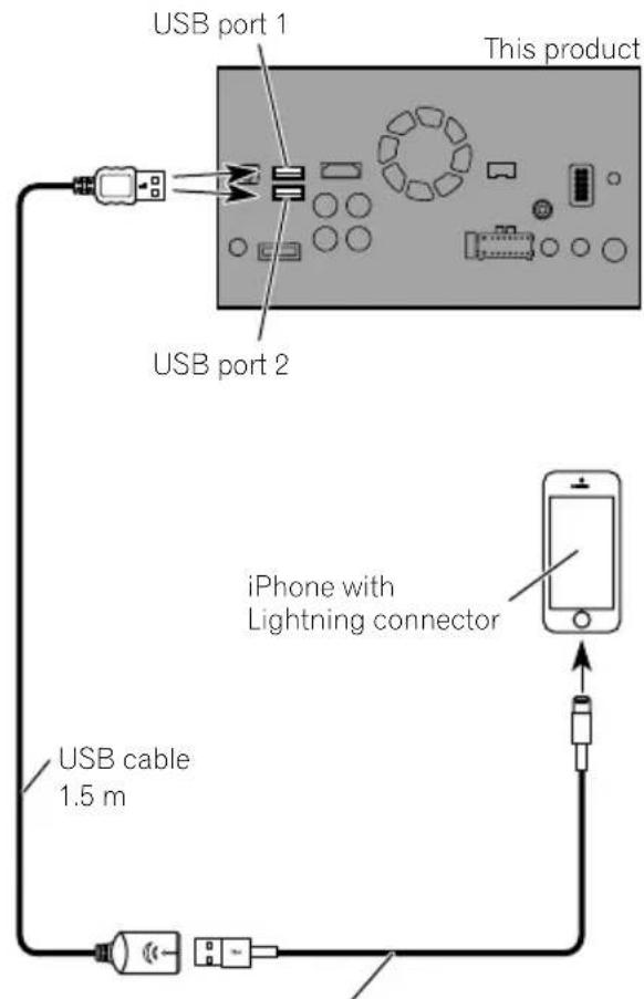
USB interface cable for iPod / iPhone (CD-IU52) (sold separately)
ConnectingviatheHDMIport (iPhone)
F88DAB
Thefollowingcablesarerequiredforthecom- nection.
- HDMIinterfacecableforiPod/iPhone (CD-IH202)(soldseparately)
- USBInterfacecableforiPod/iPhone(CD-IU52)(soldseparately)
LightningDigitalAVAdapter(AppleInc. products)(sold separately)
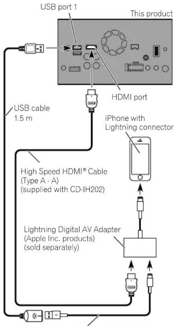
USB interface cable for iPod / iPhone (CD-IU52) (sold separately)

Note
WhenyouconnecttheHighSpeedHDMI Cable, usethelocktietofixitsecurely.
Fordetails,refertoSecuringtheHighSpeed HDMI® Cableonpage20.
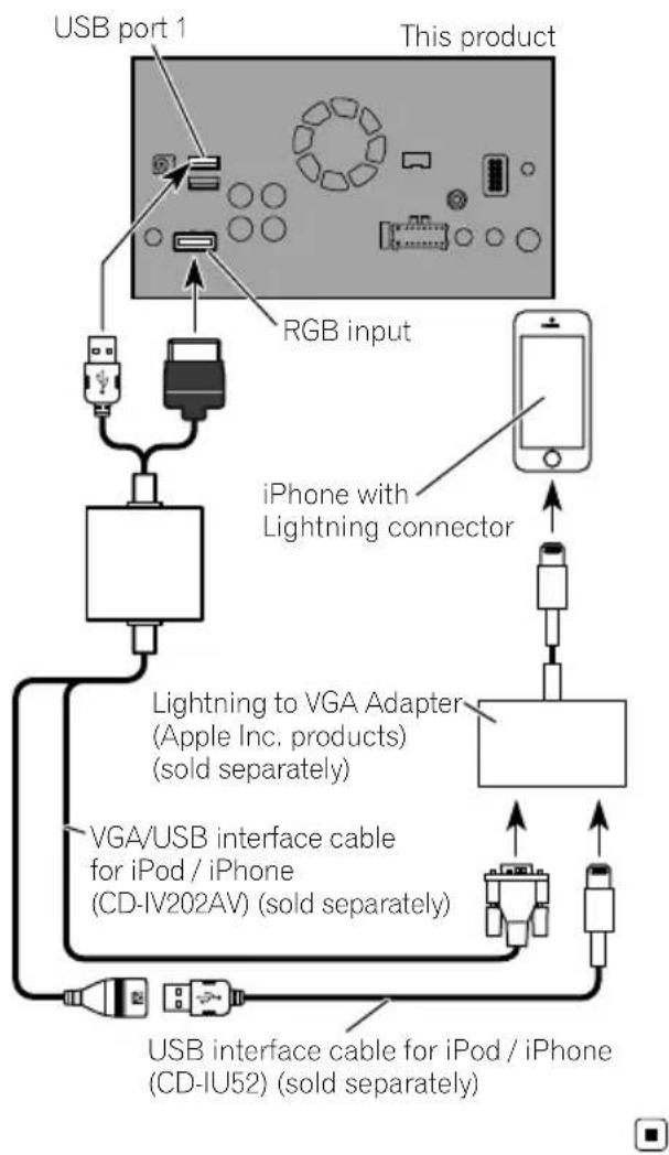
ConnectingviatheRGBinput (iPhone)
F80DAB
980DABFG
30BT
F9880DAB
F9880BT
Thefollowingcablesarerequiredforthecom- nection.
VGA/USBInterfacecableforiPod/iPhone (CD-IV202AV)(soldseparately)
- USBInterfacecableforiPod/iPhone(CD-IU52)(soldseparately)
LightningtoVGAAAdapter(AppleInc.pro
ducts)(soldseparately)
Connection
ConnectingviatheAUXinput (iPhone)
TheUSBInterfacecableforiPod/iPhone(CD-IU201V)(soldseparately)isrequiredforthe connection.
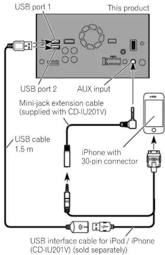
ConnectinganiPhonewith 30-pinconnector

Notes
- Fordetailsonhowtoconnectanexternal deviceusingaseparatelysoldcable,refertothe manualforthecable.
- Fordetailsconcerningtheconnection, operationsandcompatibilityofiPhone,refertoOperationManual.
ConnectingviatheRGBinput (iPhone)
TheUSBInterfacecableforiPod/iPhone(CD-IU201S)(soldseparately)isrequiredforthe connection.
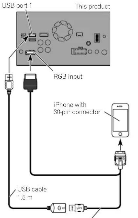
USB interface cable for iPod / iPhone (CD-IU201S) (sold separately)

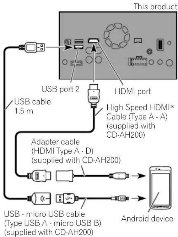
ConnectingtheAndroid device
F88DAB
AppConnectivityKit(CD-AH200)(soldseparately)isrequiredfortheconnection.

Notes
- Fordetailsonhowtoconnectanexternal deviceusingaseparatelysoldcable,referto the manualforthecable.
- FordetailsconcerningtheconnectionandoperationsofAndroiddevice,refertoOperation Manual.
- WhenyouconnecttheHighSpeedHDMI Cable,usethelocktietofixitsecurely.
Fordetails,refertoSecuringtheHigh SpeedHDMI® Cableonpage20.
ConnectingviatheHDMIport (Androiddevice)
ConnectingviatheMHLport (Androiddevice)
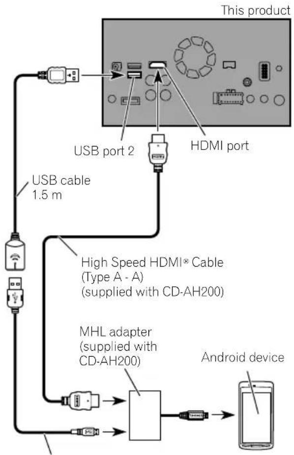
USB - micro USB cable
(Type USB A - micro USB B)
(supplied with CD-AH200)
ConnectingviatheUSB port(Androiddevice)
TheUSBInterfaceableforusewithAndroid devices(CD-MU200)(soldseparately)isrequiredfortheconnection.
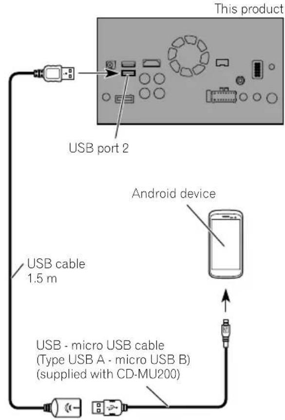


Note
Fordetailsonhowtoconnectanexternaldevice usingaseparatelysoldcable,refertothemanual forthecable.
SecuringtheHighSpeed HDMI® Cable
F88DAB
BesuretofixtheHighSpeedHDMI Cable withthelocktie,whenyouconnecttheexternaldevicewiththeHighSpeedHDMI Cable.
1InserttheHighSpeedHDMI Cableinto theHDMIport.
2Wrapthelocktiearoundthehook abovetheHDMIportandtheHighSpeed HDMI Cable,andthentightenittosecure theHighSpeedHDMI Cable.

① Hook
②Locktie
③HighSpeedHDMI Cable
Donottightenupthelocktiemorethan necessary.
Connectingarearviewcamera
Whenthisproductisusedwitharearview camera,itispossibletoautomaticallyswitch fromthevideotorearviewimagewhenthe gearstickismovedtoREVERSE(R).Camera Viewmodealsoallowsyoutocheckwhatis behindyouwhiledriving.

WARNING
USEINPUTONLYFORREVERSEORMIRROR
IMAGEREARVIEWCAMERA.OTHERUSEMAY
RESULTINJURYORDamage.

CAUTION
- Thescreenshotimagemayappearreversed.
- Therearviewcameraisusedasanaidto keeppaneyeontrailers,orbackingintoatight parkingspot.Donotusethisfunctionforentertainmentpurposes.
- Objectsinrearviewmayappearcloserormoredistantthaninreality.
- Please notethat the imageareashown by the rearviewcameramaydifferslightlywhen full-screenimagesaredisplayed when backing andwhen checkingtherearofthevehicle whilemovingforward.
Connection
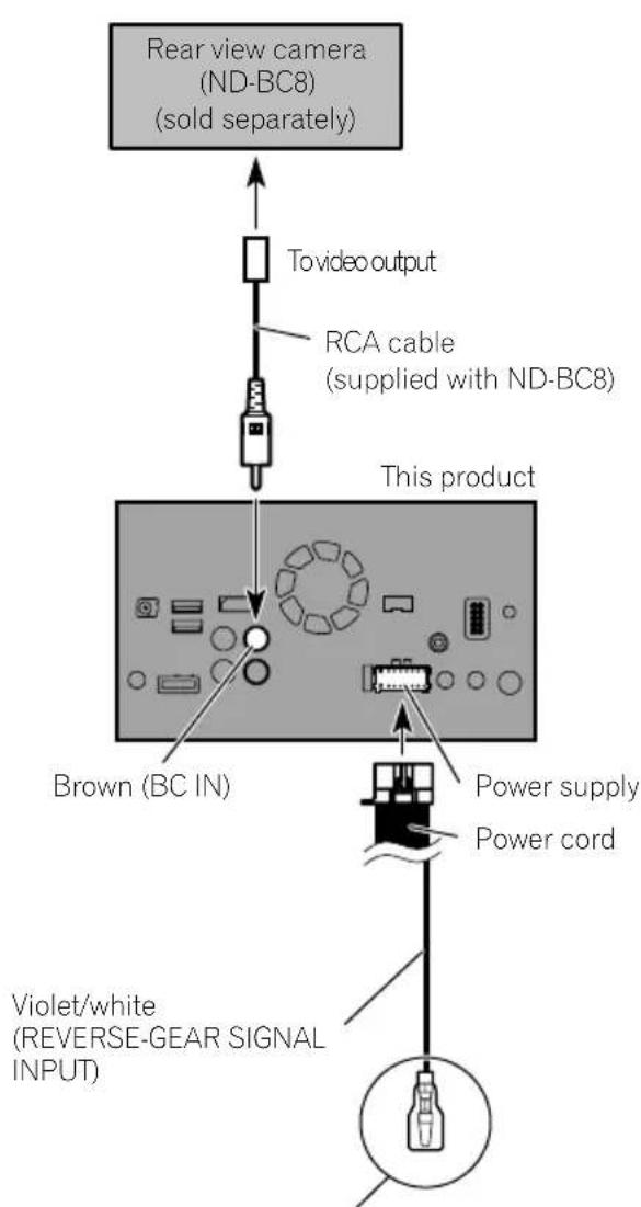
Formoredetailsaboutthewiring,refertoConnecting thepowercord(2)onpage10.

Notes
- Thismodeisavailablewhentherearview camerasettingissetto "On".(Fordetails, refereToOperationManual.)
- Connectthisproducttotherearviewcamera only. Donotconnecttoanyother equipment.
Connectingtheexternal videocomponent
UsingAVinput
You can connect an external video component or external camerat this product.
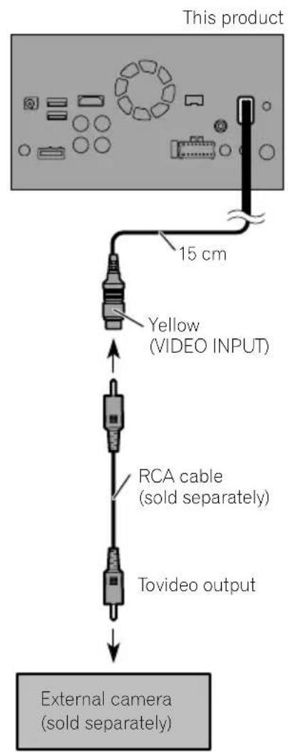
Connectinganexternalcamera

Note
ThismodeisavailablewhentheshettingofAV inputissetto"Camera".(Fordetails,refertoOperationManual.)
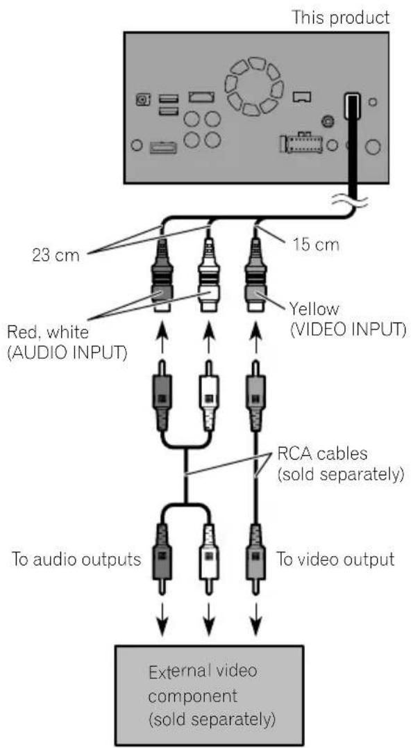
Connectingthevideocomponent

Note
ThismodeisavailablwwhenthesettingofAV input is set to "Source". (For details, refer to OperationManual.)
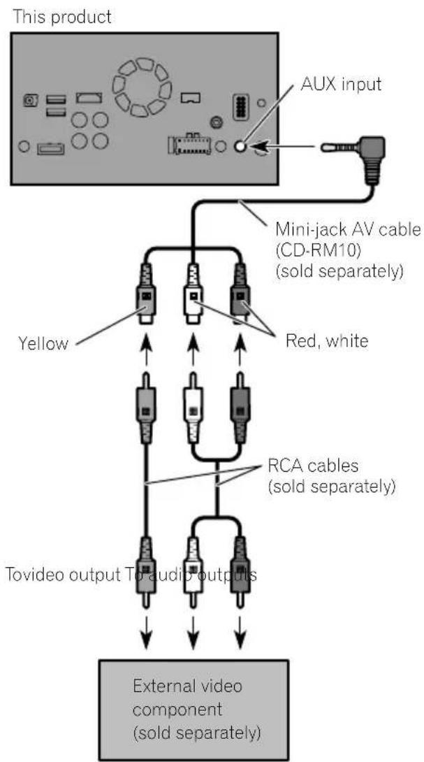
UsinganAUXinput

Notes
- Thismodeisavailablewhenthesettingof AUX input is set to "On". (For details, refer to OperationManual.)
- When connecting an external video component using a mini-jackAV cable, use separately sold AUX extension cable as necessary.
Connection

CAUTION
Besuretouseamini-jackAVcable(CD-RM10) (soldseparately)forwiring.Ifyouuseother cables,thewiringpositionmightdifferresulting indisturbedimagesounds.
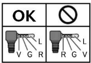
L: Left audio (White)
R:Rightaudio(Red)
V: Video (Yellow)
G:Earth

ConnectinganHDMIdevice
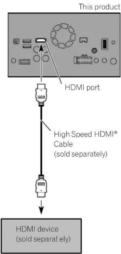
F88DAB

Notes
- FordetailsconcerningtheoperationsofHDMI device,refertoOperationManual.
- WhenyouconnecttheHighSpeedHDMI Cable,usethelocktietofixitsecurely.
Fordetails,refertoSecuringtheHigh SpeedHDMI Cableonpage20.
Connectingthereardisplay
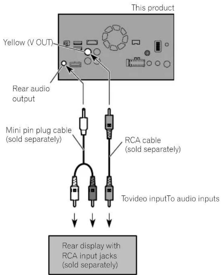
Whenusingareardisplay connectedorearvideooutput

WARNING
NEVERinstallthereardisplayalocation thatenablesthedrivertowatchthevideo sourcewhiledriving.
Thisproduct'searvideooutputisforconnection ofadisplaytoenablepassengersintherear seatstwatchthevideosource.
Precautionsbefore installation

CAUTION
- Neverinstallthisproductinplaceswhere, orinamannerthat:
—Couldinjurethedriverorpassengersif thevehiclestopssuddenly.
Mayinterferewiththedriver'soperatiofthevehicle,suchasonthefloorinfrontofthedriver'sseat,orclosetothesteeringwheelorgearstick. - Makesurethereisnothingbehindthedashboardorpanellingwhendrillingholesinthem.Becarefulnottodamagefuellines,brakelines,electroniccomponents,communicationwiresorpowercables.
- Whenusingscrews, donotallowthemto comeintocontactwithanyelectricallead. Vibrationmaydamagewiresorinsulation, leadingtoashortcircuitorotherdamage tothevehicle.
Toensureproperinstallation,besureto usethesuppliedpartsinthemannerspecified.Ifanypartsarenotsuppliedwith thisproduct,usecompatiblepartsinthe mannersspecifiedafteryouhavetheparts' compatibilitycheckedbyyourdealer.If partsotherthansuppliedorcompatible onesareused,theymaydamageinternal partsofthisproductortheymaywork looseandtheproductmaybecometdetached. - Itisextremelydangeroustoallowcables tobecomewoundaroundthesteeringcolumngearstick.Besuretoinstallthis product,itscables,andwiringawayinsuchsothattheywillnotobstructorhinderdriving.
- Makesurethatleadscannotgetcaughtin adoorortheslidingmechanismofaseat, resultinginashortcircuit.
-
Please confirm the proper function of your vehicle'sotherequipment after installation of this product.
-
Donotinstallthisproductwhereitmay(i) obstructthedriver'svision,(ii)impairthe performanceofanyofthevehicle'soperatingsystemsaftetyfeatures,includingairbags,hazardlampbuttonstoriii) impairthedriver'sabilitytosafelyoperatethevehicle.
Installthisproductbetweendriver's seatandfrontpassengerseatsothatit willnotbehitbythederiverorpassengerif thevehiclestopsquickly. - Neverinstallthisproductinfrontofor nexttotheplaceinthedashboard,door, orpillarfromwhichoneofyourvehicle's airbagswoulddeploy.Pleaserefotour vehicle'sowner'smanualforreference to thedeploymentareaofthefrontalairbags.
- Failuretofollowalloftheseprecautions mayresultinseriousinjuryordeath.
Toavoidelectromagnetic interference
Inordertopreventinterference,setthefollowingitemsfasfaraspossiblefromthisproduct,othercablesorleads:
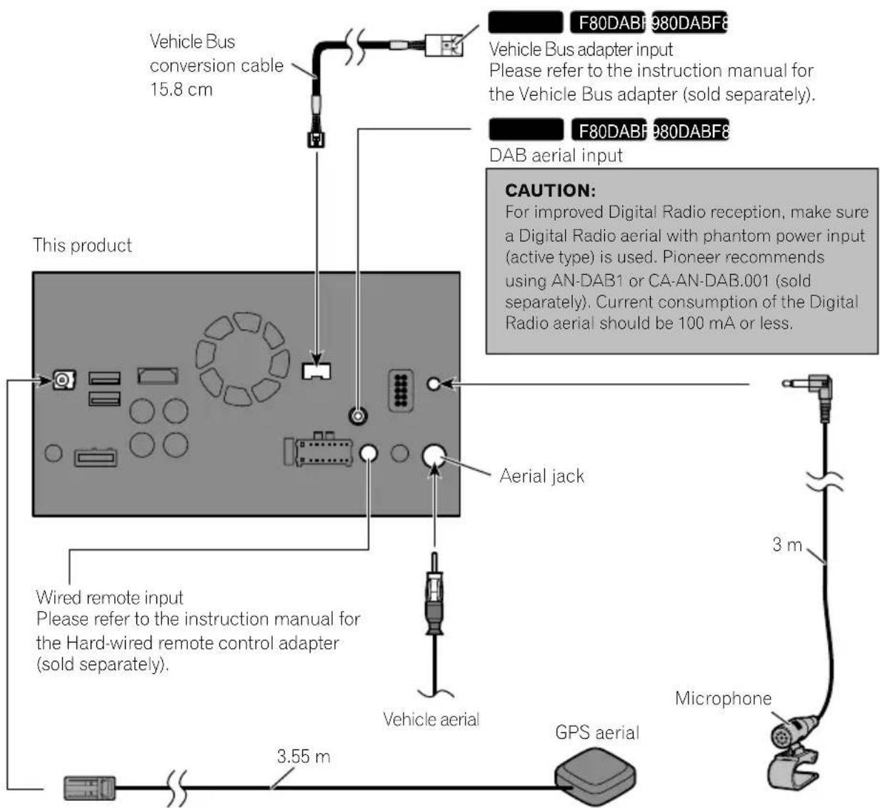
FM,MW/LWaerialanditslead
DABaerialanditslead(forAVIC-F88DAB, AVIC-F80DABandAVIC-F980DAB)
GPSaerialanditslead Inaddition,youshouldlayorrouteeaerial leadasfaraspossiblefromotheraerialleads. Donotbind,layorroutethemtogether,or crossthem.Electromagneticnoisewillincreaseasethepotentiaforerrorsinthevehicle's locationdisplay.
Beforeinstalling
- Consultwithyournearestdealerinstallationrequiresdrillingholesorthermodificationsofthevehicle.
Installation
- Beforemakingafinalinstallationofthis product, temporarily connect the wiring to confirm that the connections are correct and the system works properly.
ForAVIC-F88DABandAVIC-F80DABusers
Donotinstallthisproductinpositionwhere theopeningoftheLCDpanelisobstructedby anyobstacles,suchasthegearstick.Before installingthisproduct,besuretoleavesuftificientspacesothattheLCDpaneldoesnobot-structthegearstickwhenitisfullyopened. Thismaycauseinterferencewiththegearstick,oramalfunctionofthemechanismof thisproduct.
Installingthisproduct Installationnotes
- Donotinstallthisproductinplacesubject tohightemperaturesorhumidity,suchas:
-Placesclosetoahater,ventorairconditioner.
-Placesexposedtodirectsunlight,such asontopofthedashboard.
—Placesthatmaybeexposedtorain, suchasclosetothedoororonthevehicle'sfloor.
Installthisproductinanareastrongenoughtobearitsweight.Chooseposition wherethisproductcanbefirmlyinstalled, andinstallitsecurely.Ifthisproductisnot securelyinstalled,thecurrentlocation of thevehiclecannotbedisplayedcorrectly.
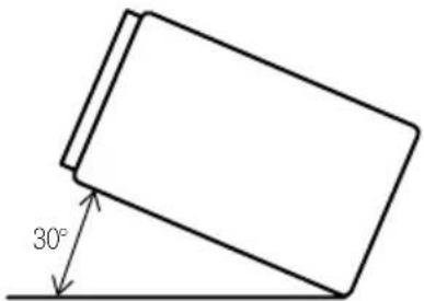
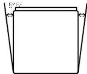
Installthisproducthorizontallyonasurfacewithin0to30degreestolerance(within5degreestotheleftorright).Improperinstallationoftheproductwiththesurface tiltedmorethanthesetolerancesincreases thepotentialforerrorsinthevehicle'slocationdisplay,andmightotherwisecausereduceddisplayperformance.
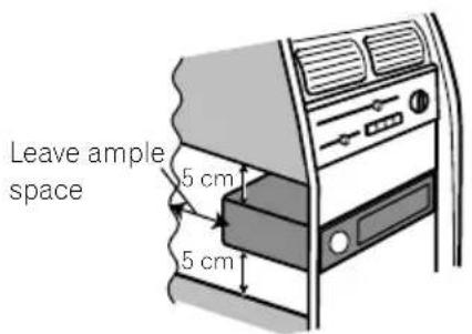
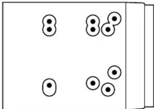
- Wheninstalling, toensureproperheatdispersalwhenusingthisproduct, makesure youleaveamplespacebehindtherear panelandwrapanyloosecablessothey arenotblockingthevents.
Installation
Thecordsmustnotcovertheareashown inthefigurebelow.Thisisnecessaryto allowtheamspsandnavigationmechanism todissipateheat.
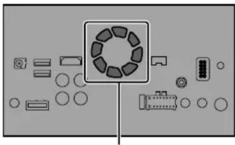
Donotcoverthisarea.
- Thesemiciconductorlaserwillbedamaged ifitoverheats,sodon'tinstallthisproduct anywherehot—foreinstanee,nearaheater outlet.
Partssupplied
Partsmarked(*)arepre-installed.
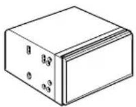
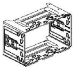
ThisproductHolder*
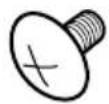
Trussheadscrew (5mm×8mm) (6pcs.)
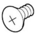
Flushsurfacescrew (5mm×9mm) (6pcs.)
Trimming*ExtractionKey
Beforeinstallingthisproduct
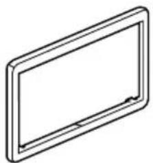
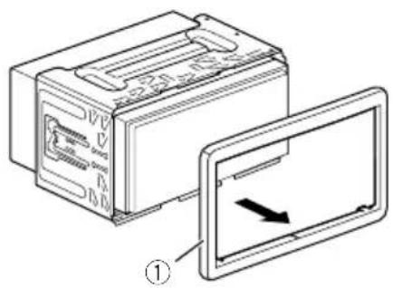
1Removethetrimring.
Extendopandbottomofthetrimringoutwardstoremovethetrimring.
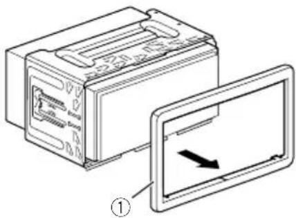
①Trimming
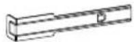
2Insertthesuppliedextractionkeysinto bothsidesoftheunituntiltheyclickinto place.
3Pulltheunitoutoftheholder.
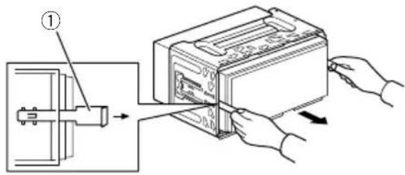
①Extractionkey
Installationwiththeholder
1Installtheholderintothedashboard.
2Securethemountingsleevebyusinga screwdrivertobendthemetaltabs (90^) intoplace.
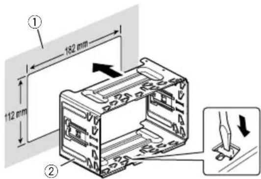
① Dashboard
②Holder
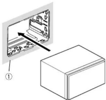
3Installthisproducttotheholder.
① Dashboard
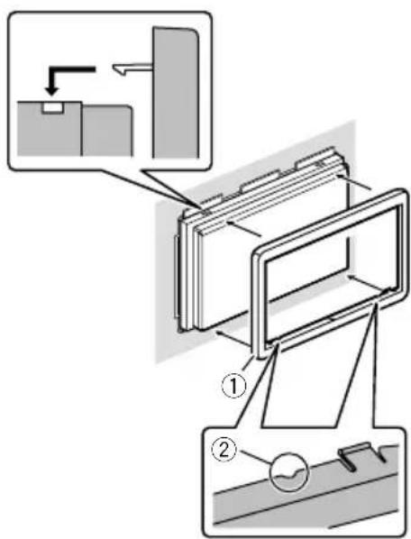
4Attachthetrimring.
①Trimming
②Groove
Attachthetrimringwiththesidewithagroovefacingdownward.
Installationusingthescrew holesonthesideofthisproduct
- Fasteningthisproducttothefactory radio-mountingbracket.
Positionthisproductsothatitsscrewholes arealignedwiththescrewholesofthebracket,andtightenthescrewsatthreelocations oneachside.
Useeitherthetrussheadscrews(5mm× 8mm)orflushsurfacedrives(5mm× 9mm),dependingontheshapeofthebracket'sscrewholes.
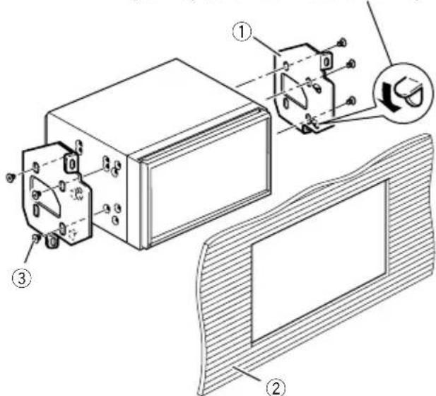
If the pawl interferes with installation, you may bend it down out of the way.
①Factoryradio-mountingbracket
②Dashboardorconsole
③ Trussheadscreworflushsurfacescrew Besuretousethescrewssuppliedwith thisproduct.
InstallingtheGPSaerial
CAUTION
DonotcuttheGPSaerialleadtoshortenit oruseanextensionomakeitlonger.Alteringtheaerialcablecouldresultinashortcircutormalfunctionandpermanentdamage tothisproduct.
Installationnotes
- Theaerialshouldbeinstalledonalevelsurfacewhereradiowaveswillbeblockedaslittleaspossible.Radiowavescannnotbereceivedbytheaerialifreecctionfromthesateliteisblocked.
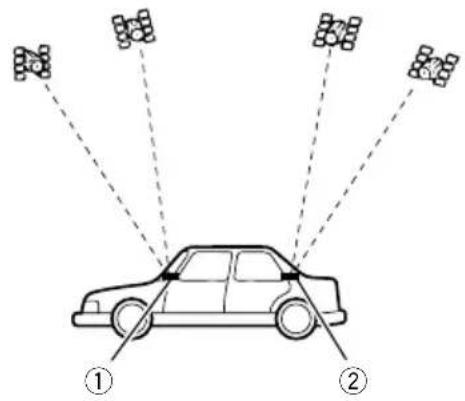
① Dashboard
(2)Rearshelf
- WheninstallingtheGPSaerialinsidethe vehicle, besuretousethemetalsheetprovidedwithyoursystem.Ifthisisnotused, thereceptionsensitivitywillbepoor.
- Donotcuttheaccessymetalsheet.This wouldreducethesensitivityoftheGPSaerial.
Takecarenottopulltheaerialleadwhen removingtheGPSaerial.Theleadmaybe- comedetached. - DonotpainttheGPSaerial, asthismayeffectitsperformance.
Wheninstallingtheaerialinsidethevehicle(onthedashboardor rearshelf)

WARNING
DonotinstalltheGPSaerialoveranysensorsorventsonthedashboardofthevehicle, asdoingsomayinterferewiththeproperfunctioningofsuchsensororsventsandmaycompromisetheabilityofthemetalsheetundertheGPSaerialtoproperlyandscurelyaffixtothedashboard.
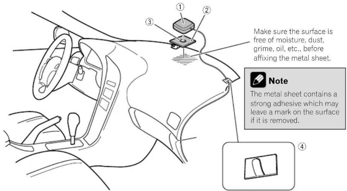
①GPSaerial
②Metalsheet
Peelofftheprotectivesheetonthear.
③Double-sidedtape
④ Clamps
Useclampstosecurtheleadwherenecessaryinsidethevehicle.
Affixthemetalssheetontthesurfaceaslevelas possiblewhereetheGPSaerialfacesthewindow.AffixtheGPSaerialonthemetalssheet usingthedouble-sidedtape.

Notes
- Whenattachingthemetalsheet,donotcut itintosmallpieces.
- Somemodelsusewindowglasssthatdoesn'tallowssignalsfromGPSsatellitestopassthrough.Onsuchmodels,installtheGPSaerialontheoutsideofthevehicle.

Installation
Installingthemicrophone
Installhemicrophoneinaplacewhereits directionanddistancefromthedriver makeiteasiesttopickupthedriver'svoice.
- Besuretoturnoff(ACCOFF)theproduct beforeconnectingthemicrophone.
- Dependingonthevehiclemodel,themicrophonecablelengthmaybetooshortwhenyoumountthemicrophoneonthe sunvisor.Insuchcases,installthemicrophoneonthesteeringcolumn.
Partssupplied
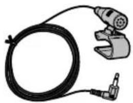

MicrophoneDouble-sidedtape
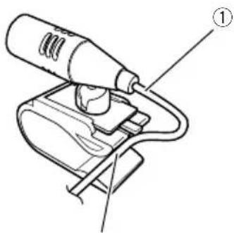
Mountingonthesunvisor 1Fitthemicrophoneleadintothe groove.
2
① Microphonelead
②Groove
2Attachemicrophonecliptothesun visor.
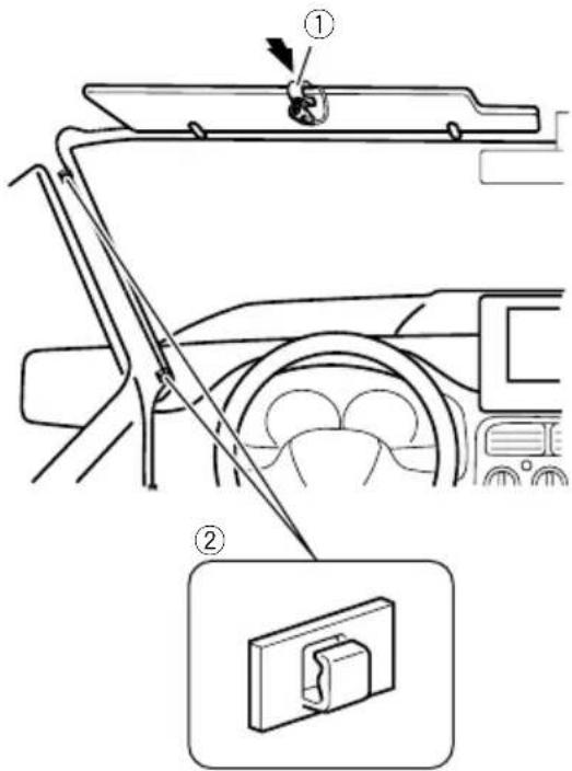
① Microphoneclip
② Clamps
Useseparatelysoldclampstosecurethe leadwherenecessaryarsinsidethevehicle.
Installthemicrophoneonthesunvisorwhen itisintheupposition.Itcannotrecognisethe driver'svoiceifthesunvisorisinthedownposition.
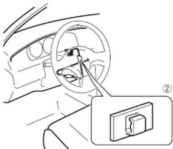
Installationonthesteeringcolumn
1Detachthemicrophonebasefromthe microphoneclipbyslidingthemicrophone basewhilepressingthetab.
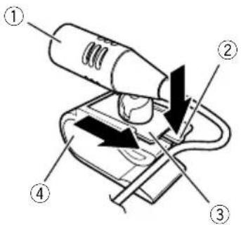
① Microphone
②Tab
③ Microphonebase
④ Microphoneclip
2Mountthemicrophoneonthesteering column.
Installthemicrophoneonthesteeringcolumn,keepingitawayfromthesteeringwheel.
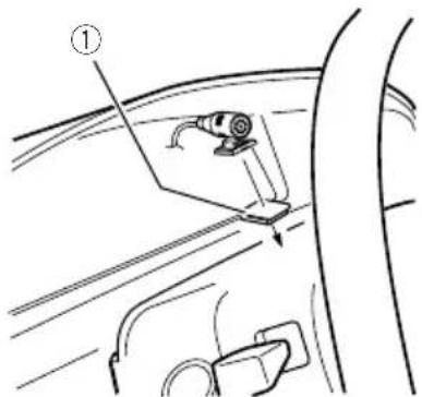

①Double-sidedtape
② Clamps
Useseparatelysoldclampstosecarethe leadwherenecessaryarsidethevehicle.
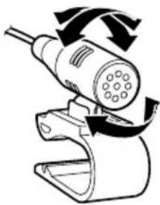
Adjustingthemicrophoneangle
Themicrophoneanglecanbeadjusted.

Afterinstallation
Afterinstallingthisproduct
1Reconnectthenegative(-)terminalof thevehicle'sbattery.
First, double-check that all connections are correct and that this product is installed correctly. Reassemble all vehicle components that you previously removed. Then reconnect thenegative(-) cable tothenegative(-) terminal of the battery.
2Starttheengine.
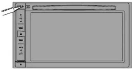
3PresstheRESETbutton.
PresstheRESETbuttononthisproductwithapointedobjectsuchasthetipofapen.
F88DABF30DAB
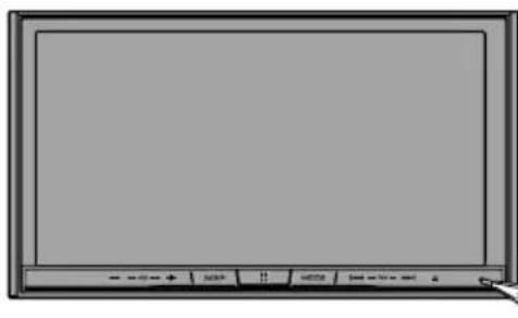
F980DAB F980BT F9880DAB F9880BT
Someofthesettingsandrecordedcontents willnotbereset.
4Changethesettingsasdesired.
Fordetailsconcerningoperations,referto OperationManual.
5Drivennanunobstructedroaduntil theGPSstartsreceivingthesignalnormally.

Note
Afterinstallingthisproduct, besuretocheckata safeplacethathevehicleisperformingnormally.

Précautions
Installationdumicrophone64
-Piècesfournies64
-Installationsurlepare-soleil64
-Installationsurlacolonned direction65
-Réglagedel'angledumicrophone65

Apresl'installation
1Retirezl'anneaudegarniture.
Étirezversl'extérieurlapartiessupérieureetinférieuredel'anneaudegarniturepourlerétirer.
①Anneaudegarniture
Installationdumicrophone
Installationsurlepare-soleil
Installationsurlacolonned direction
1Retirezlabasedumicrophonedel'a-grafepourmicroenfaitglisserlabasedumicrophonetoutenenfonçantlalanguette.
① Microphone
② Languette
③ Basedumicrophone
④Agrafepourmicro
2Montezlemicrophonesurlacolonne dedirection.
Installezlemicrophonesurlacolonnededirection,adistanceduvolant.

©2016PIONEERCORPORATION.
Allrightsreserved.
©2016PIONEERCORPORATION.
Tousdroitsdereproductionetde