PA 19000 M - Air-conditioner SIEMENS - Free user manual and instructions
Find the device manual for free PA 19000 M SIEMENS in PDF.
| Product type | Mobile monobloc air conditioner |
| Brand | Siemens |
| Model | PA 19000 M |
| Cooling capacity | 1900 W (according to EN14511) |
| Dehumidification capacity | 36 L/day |
| Main functions | Air conditioning (maximum and silent), dehumidification, air purification |
| Power supply | 220-240 V, 50 Hz, grounded plug |
| Maximum power consumption | 975 W |
| Recommended fuse | 10 A slow-blow |
| Energy efficiency class | D |
| Operating ambient temperature (air conditioning) | 20 °C to 35 °C |
| Operating ambient temperature (dehumidification) | 18 °C to 35 °C |
| Filter type | Washable base filter + purification filter (replace annually) |
| Accessories included | Air exhaust hose, diffuser, suction cup |
| Optional accessories | Window/balcony slide kit (PA11000Z), through-wall kit (PA10000Z) |
| Normal noise level | Operating sounds: pump, compressor, refrigerant (normal) |
| Routine maintenance | Clean the base filter with clean water regularly |
| End-of-season storage | Fold the hose backwards and attach it with the hook |
| Safety | Minimum distance of 20 cm from surfaces; do not cover air inlets/outlets; disconnect before cleaning |
| Repairability | Repair by certified technician; use original Siemens parts |
Frequently Asked Questions - PA 19000 M SIEMENS
User questions about PA 19000 M SIEMENS
0 question about this device. Answer the ones you know or ask your own.
Ask a new question about this device
Download the instructions for your Air-conditioner in PDF format for free! Find your manual PA 19000 M - SIEMENS and take your electronic device back in hand. On this page are published all the documents necessary for the use of your device. PA 19000 M by SIEMENS.
USER MANUAL PA 19000 M SIEMENS
Instructions for Use
Mode d'emploi
natural_image
3D rendering of a Siemens air purifier unit with control panel and ventilation slots (no text or symbols on the device itself)PA19000M
PA18100M
natural_image
3D diagram of a kitchen appliance with a handle and arrow, labeled Abb. 1 (no text or symbols on the main subject)natural_image
3D rendering of a mechanical component with a bucket and pipe pouring liquid, labeled Abb. 7 (no text or symbols on the diagram itself)natural_image
Close-up of a mechanical component with two white arrows pointing upward, labeled 'Abb. 12' (no other text or symbols)natural_image
Illustration of a cable being inserted into a window frame, labeled Abb 14 (no text or symbols on the diagram itself)natural_image
Architectural detail showing a window with a door and adjacent structure, labeled 'Abb. 16' (no other text or symbols)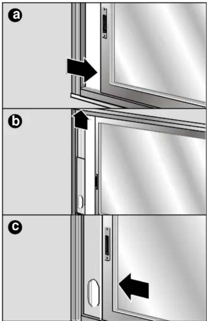
Festinstallation
natural_image
Mechanical assembly showing a pipe passing through a processing unit with a label 'Abb. 18' (no other text or symbols visible)natural_image
Close-up of a metallic knob with temperature and angle markings (20°, 30°) and label 'Abb. 20' at bottom right (no other text or symbols)natural_image
3D rendering of a kitchen appliance pouring liquid into a bucket on tiled floor, labeled Abb. 21 (no text or symbols on the main subject)natural_image
3D rendered mechanical component with threaded spring and mounting base, labeled Abb. 22 (no text or symbols on the component itself)natural_image
3D rendered mechanical knob or dial with no visible text or symbols, labeled 'Abb. 24' at bottom right (no other readable text or symbols)natural_image
Diagram showing a device with two arrows pointing to a panel and a base, labeled 'Abb. 25' (no text or symbols on the diagram itself)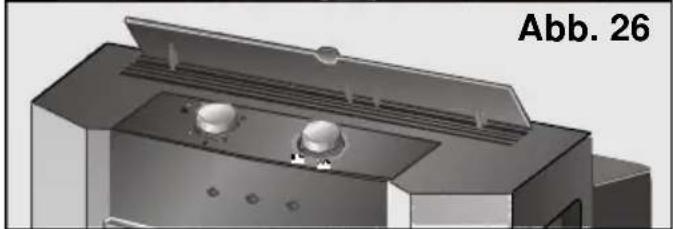
natural_image
3D rendering of a mechanical device with two circular components and a lid, labeled Abb. 26 (no text or symbols on the device itself)natural_image
3D rendered mechanical component with labeled parts (no readable text or symbols)natural_image
Exterior view of a rectangular plastic enclosure with four compartments (no text or symbols visible)Abb. 29
natural_image
Mechanical assembly diagram showing a lever mechanism with a white arrow indicating direction (no text or symbols present)natural_image
3D rendering of a Siemens industrial air duct system (no text or symbols visible)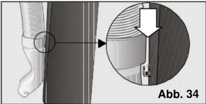
natural_image
Technical diagram showing a mechanical component with an inset close-up view labeled 'Abb. 34' (no readable text or symbols)Environmental protection
Recommendations for the disposal of packaging 21
Recommendations for the disposal of your old appliance ....21
Recommendations for saving energy ....21
Important Information
Before connecting your appliance....22
Your new appliance
Description of the appliance ....23
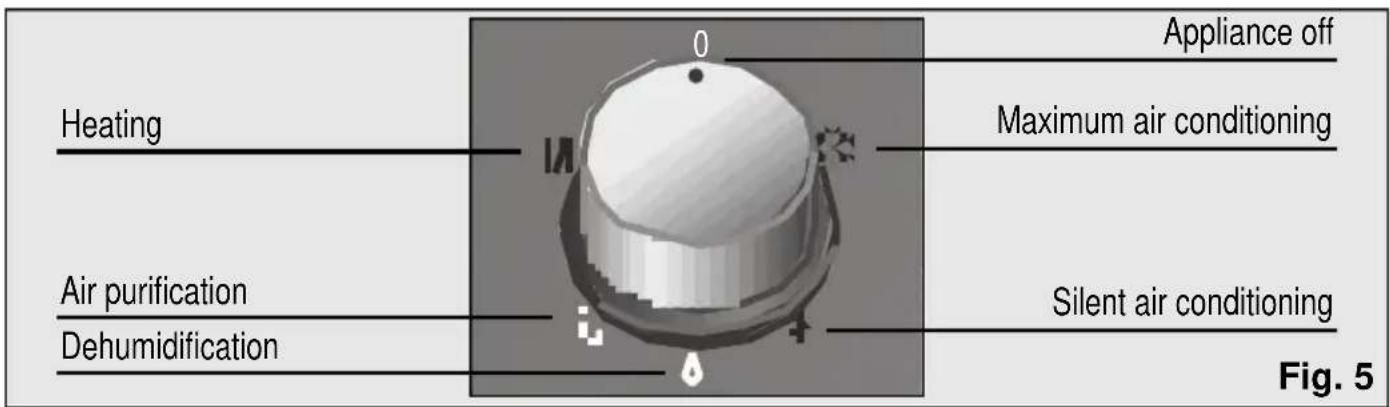
Control panel....24
Description of accessories....25
Requirements for use
Requirements for use ....25
Transportation requirements ....26
Instructions for Use
Cooling....26
Ways of releasing air outdoors 27
Dehumidification 29
Air purification ....30
Heating 30
Cleaning and Maintenance
Cleaning the appliance ....31
Cleaning and changing the purifying filters....31
Storage requirements ....32
Prior to use at change of season ....32
Things to check before calling the Technical Service
General operation ....33
Noise 33
Technical service / Warranty / Technical Information....34
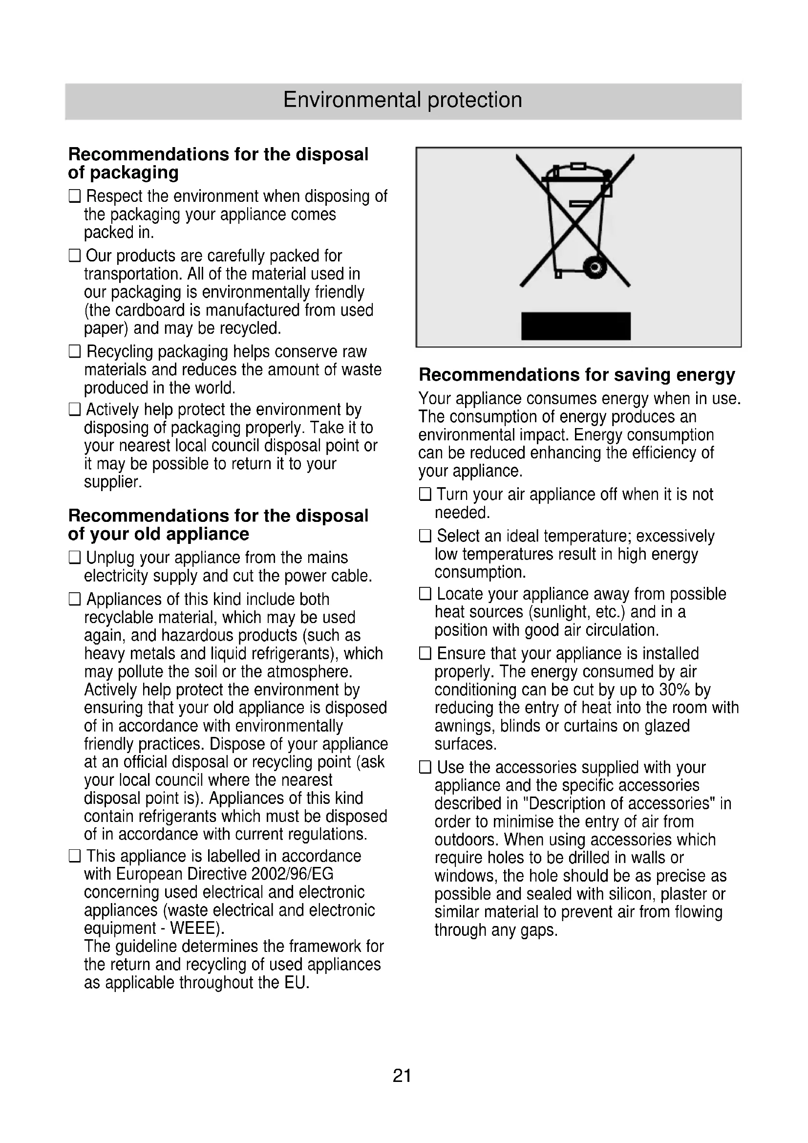
Recommendations for the disposal of packaging
☐ Respect the environment when disposing of the packaging your appliance comes packed in.
☐ Our products are carefully packed for transportation. All of the material used in our packaging is environmentally friendly (the cardboard is manufactured from used paper) and may be recycled.
□ Recycling packaging helps conserve raw materials and reduces the amount of waste produced in the world.
□ Actively help protect the environment by disposing of packaging properly. Take it to your nearest local council disposal point or it may be possible to return it to your supplier.
Recommendations for the disposal of your old appliance
□ Unplug your appliance from the mains electricity supply and cut the power cable.
☐ Appliances of this kind include both recyclable material, which may be used again, and hazardous products (such as heavy metals and liquid refrigerants), which may pollute the soil or the atmosphere. Actively help protect the environment by ensuring that your old appliance is disposed of in accordance with environmentally friendly practices. Dispose of your appliance at an official disposal or recycling point (ask your local council where the nearest disposal point is). Appliances of this kind contain refrigerants which must be disposed of in accordance with current regulations.
☐ This appliance is labelled in accordance with European Directive 2002/96/EG concerning used electrical and electronic appliances (waste electrical and electronic equipment - WEEE).
The guideline determines the framework for the return and recycling of used appliances as applicable throughout the EU.
natural_image
Symbol of a trash bin crossed with a diagonal line, representing waste sorting or disposal (no text or labels)
Recommendations for saving energy
Your appliance consumes energy when in use. The consumption of energy produces an environmental impact. Energy consumption can be reduced enhancing the efficiency of your appliance.
☐ Turn your air appliance off when it is not needed.
□ Select an ideal temperature; excessively low temperatures result in high energy consumption.
☐ Locate your appliance away from possible heat sources (sunlight, etc.) and in a position with good air circulation.
☐ Ensure that your appliance is installed properly. The energy consumed by air conditioning can be cut by up to 30% by reducing the entry of heat into the room with awnings, blinds or curtains on glazed surfaces.
☐ Use the accessories supplied with your appliance and the specific accessories described in "Description of accessories" in order to minimise the entry of air from outdoors. When using accessories which require holes to be drilled in walls or windows, the hole should be as precise as possible and sealed with silicon, plaster or similar material to prevent air from flowing through any gaps.
Environmental protection
It is recommended that you follow the manufacturer's instructions concerning the air expulsion tube (see "Ways of releasing air outdoors") in order to prevent efficiency loss and unnecessary energy consumption.
☐ Avoid sharp bends on the air expulsion tube and do not lengthen it more than necessary.
☐ When expelling hot air through sliding windows, install the accessory which prevents hot air entering the room from outdoors and enhances efficiency.
☐ Make sure that the diffusion duct is positioned in such a way that the window can be closed as far as possible in order to prevent air from outdoors entering the room.
☐ Check that the sleeves (collection and diffusion) are correctly joined to the air expulsion tube. See "Ways of releasing air outdoors".
□ Make sure that the air intakes and outlets are not obstructed. Keep them clean and free of dirt, dust and foreign objects.
☐ Make sure that the filters fitted on your appliance are clean and installed properly (see "Cleaning and Maintenance").
☐ In the summer, ventilate the building when the air outdoors is at its coolest (early morning, night).
Important Information
Before connecting your appliance
☐ Read the instructions book before using the appliance for the first time. It contains important information concerning not only how to use the appliance, but also maintenance and personal safety.
□ Keep this instructions book. It may be needed by another user at a later date.
☐ Do not use the appliance when damaged.
☐ Your appliance should be assembled and connected to the mains electricity supply in accordance with the assembly instructions and current regulations. You may lose your warranty if you fail to observe these instructions.
☐ Our appliances are manufactured in accordance with current safety regulations. Only technicians instructed in these matters are authorised to repair them. Your safety is at stake.
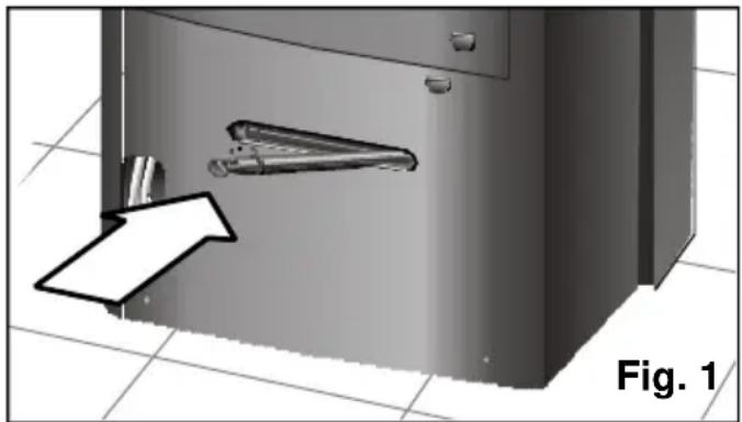
☐ Make sure that the drainage plug is fully inserted. It may have come loose during transportation, Fig. 1.
natural_image
3D diagram of a door with a handle and arrow pointing to the interior (no text or symbols)Description of the appliance
Your new appliance
Control panel
Model PA19000M
Model PA18100M
Description of accessories
| Suction pad filter | Base Purifying Active grom | Double Wall Sliding met balcony | filter window accessoryArt. No: Art. No: Art. No: PA10000Z PA11000Z 475075 | ||
| PA19000M | √ | √ | √ | ● | ● |
| PA18100M | √ | √ | √ | ● | ● |
| Approx.measurementmin / max(length x width) cm. | ∅ wall10,5 70x10/205x10 |
√ Standard accessories: These accessories are supplied with the appliance.
- Optional accessories: These accessories are available for purchase from the manufacturer's official technical service and authorised distributors.
* Optional accessories: These accessories are only available for purchase from the manufacturer's official technical service.
Requirements for use
☐ This home appliance should be connected to a 220/240 V, 50 Hz mains electricity supply via an earthed socket.
☐ It must be protected with a 10 A slow-action fuse.
☐ Should an extension lead be required, then this lead should be at least 1.5 mm^2 thick per terminal, less than 25 m long and earthed.
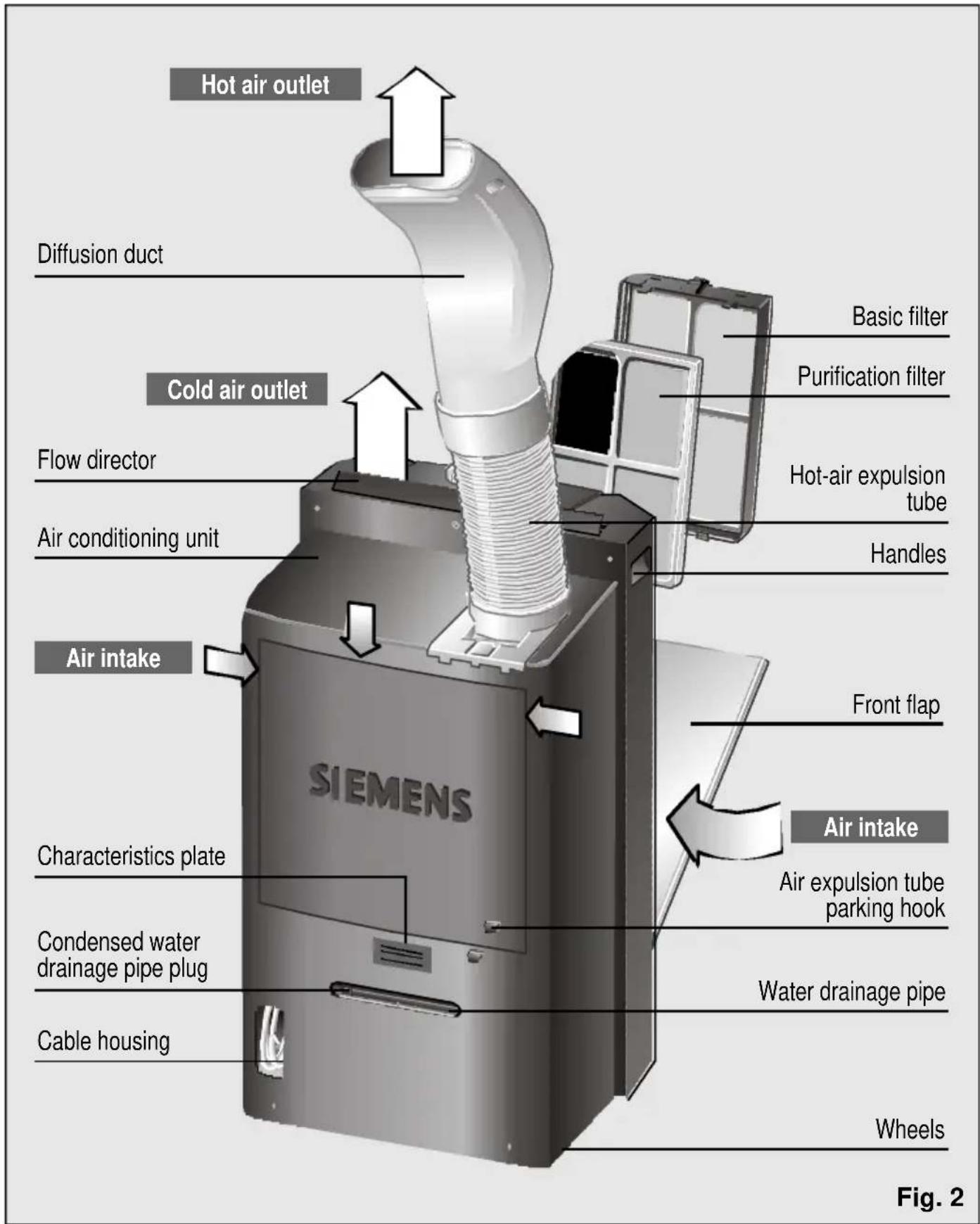
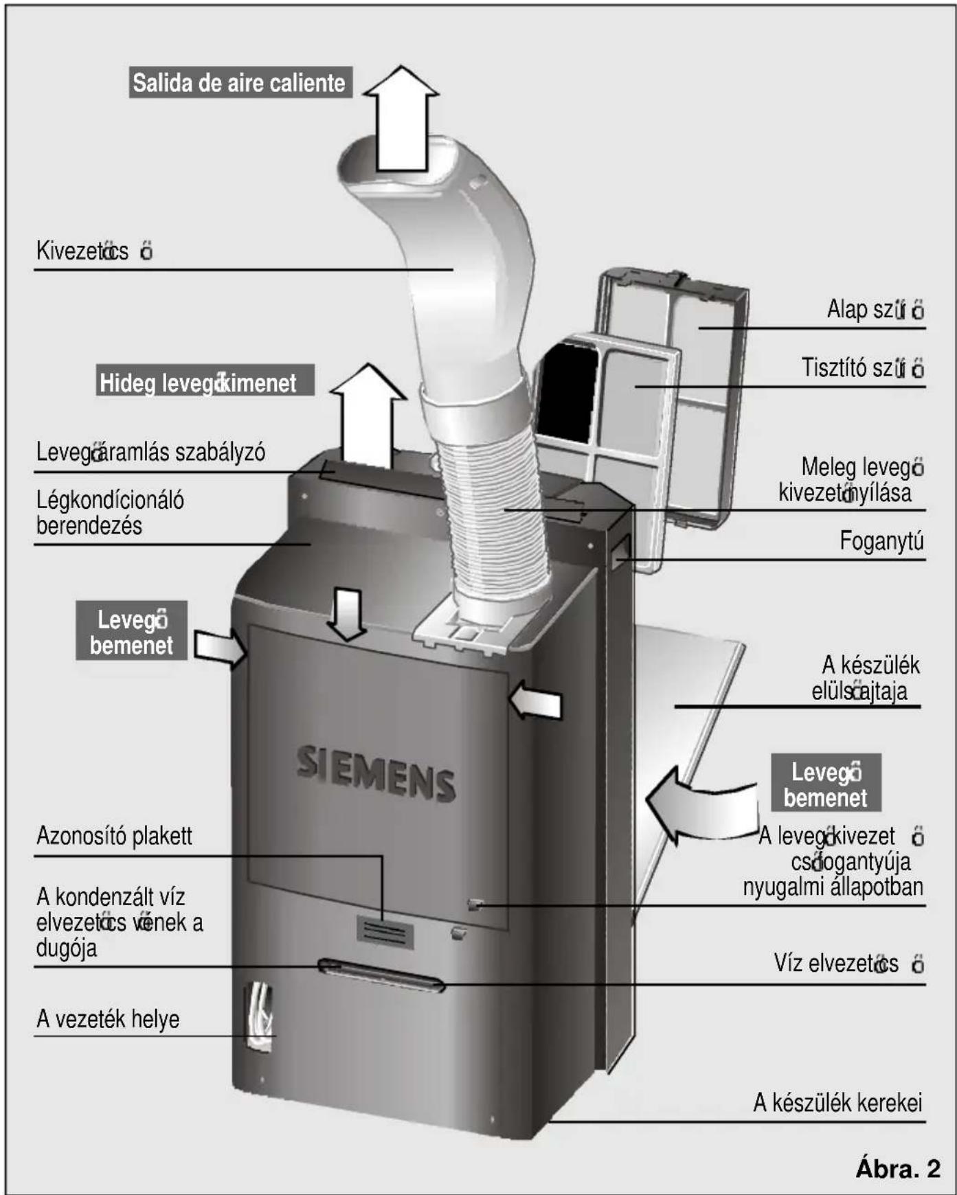
☐ There is a cavity at the back of the appliance to house the mains electricity supply cable. See Fig. 2.
☐ Do not allow water to enter your appliance and do not cover the air intakes/outlets.
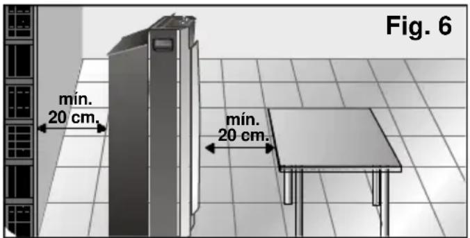
☐ For safety reasons, the appliance must be at least 20 cm away from any nearby surface before it is turned on. Fig. 6.
The mains electricity supply connection cable must only be replaced by authorised members of the manufacturer's Official Technical Service.
Requirements for use
When the appliance is turned off and then turned back on, it takes the compressor 3 minutes to start up again. This period of time is required in order to ensure correct operation.
Avoid direct contact with the air expelled through the expulsion tube.
Transportation requirements
The appliance is fitted with wheels to make it easier to move around. If necessary, you can tilt the appliance in order to move it. You should not turn the appliance back on again for a minimum period of one hour after performing this procedure.
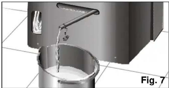
Before tilting it, empty the condensed water from the internal tank by extracting the water drainage pipe from its housing and removing the plug, Fig. 7. Do not forget to replace the plug and reinsert the pipe in its housing when the tank is empty.
natural_image
3D rendering of a metal bucket pouring liquid into a container, with no visible text or symbolsInstructions for Use
Cooling
The appliance cools and dehumidifies the air in the room at the same time in order to create a pleasant atmosphere.
□ Plug the appliance into the mains electricity supply.
☐ Lead the hot air expulsion tube outside. In order to avoid excessive noise and efficiency loss, the air expulsion tube should be positioned as shown in Fig. 14. See "Ways of releasing air outdoors".
☐ Check that the plug, Fig. 1, is fitted on the drainage pipe to prevent water from leaking onto the support surface.
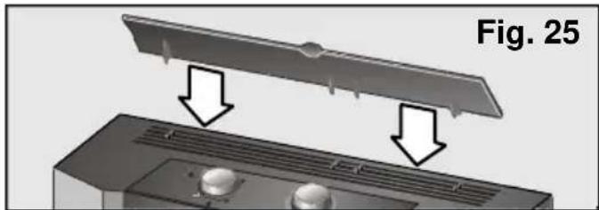
☐ Lift the air director on the top of the appliance. This air director is not installed on the appliance on PA18100M models. See figures 25 and 26 in "Heating".
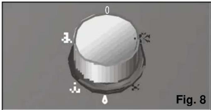
☐ Select the maximum ✗ or silent ✗ cooling function, Fig. 8. (The silent cooling function reduces the air flow on the appliance).
natural_image
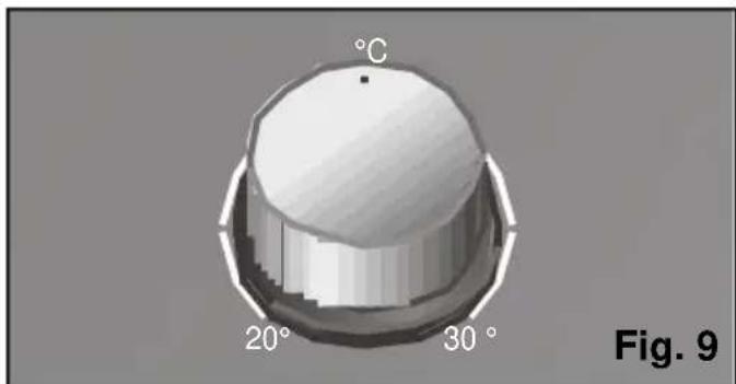
3D rendered object with labeled points (0, 1, 2, 3) and a droplet symbol, no readable text or symbols beyond labels☐ Set the thermostat to the desired temperature. Fig. 9. If the appliance turns itself off automatically because the thermostat trips, it is necessary to wait for ambient temperature to rise 2-3°C before it comes back on again.
natural_image
3D rendered mechanical component with angular measurement labels (20° and 30°) and a temperature marker (°C), no readable text or symbols beyond labels.Instructions for Use
During air conditioning, some of the condensed water produced evaporates automatically and is expelled outdoors together with the expelled air through the hot air expulsion tube.
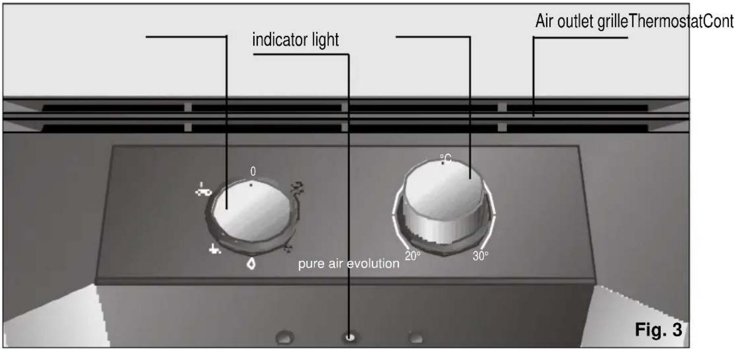
In conditions of extreme humidity, the appliance accumulates condensed water in an internal tank. When a certain level is reached an indicator light, Fig. 3, comes on indicating that the condensed water tank is full and needs to be emptied. When this happens, the appliance stops cooling the air in the room until the water is drained, as explained in "Transportation requirements", Fig. 7.
☐ It is recommended that you turn the appliance off while draining the water.
Warning!
Remember that when the appliance is turned off and turned back on, it is necessary to wait for approximately 3 minutes before the compressor starts up again. This period of time is required in order to ensure correct appliance operation.
Ways of releasing air outdoors Fitting the air expulsion tube and accessories onto the appliance
Fit the air expulsion tube assembly into the housing on the top of the appliance at the back, Fig. 11.
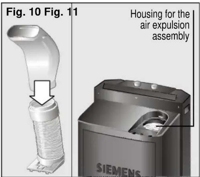
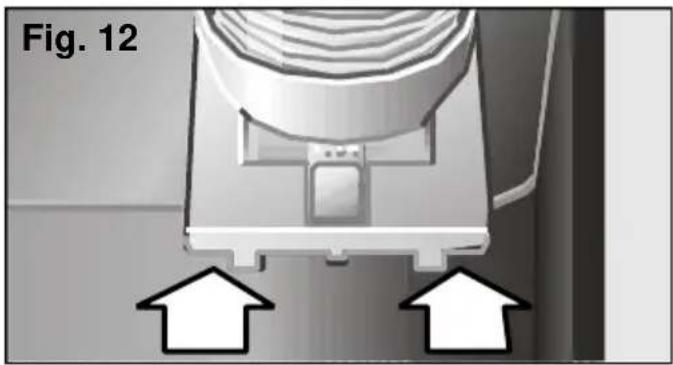
In order to fit the expulsion tube assembly properly in its housing, it is necessary to slide the sleeve into the positioning slot (as shown by the arrows on Fig. 12).
natural_image
Diagram of a mechanical component with two upward arrows indicating motion or force, labeled 'Fig. 12' (no text or symbols on the diagram itself)The diffusion duct, Fig. 10, is added when the tube assembly has been fitted onto the appliance.
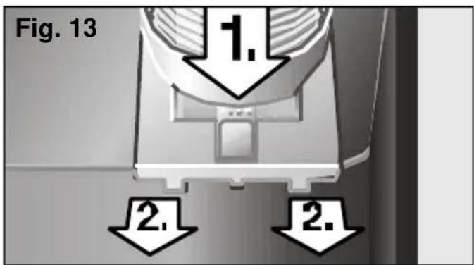
Press the "Push" tab (Fig. 13, 1) and slide out (Fig. 13, 2) to remove the assembly from the appliance.
Temporary installation
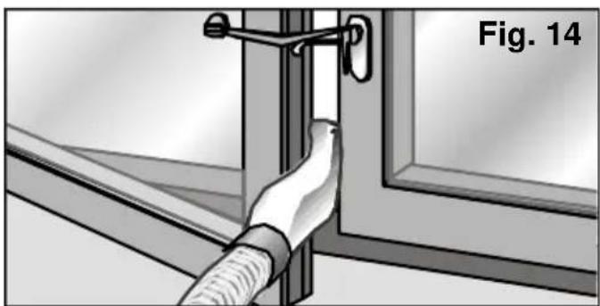
□ Open the window slightly and position the diffusion duct between the jamb and the glaze frame.
☐ Close the window as far as possible and secure it with the suction pad supplied, Fig. 14.
natural_image
Illustration of a hand holding a flexible hose to install a door frame, labeled Fig. 14 (no text or symbols on the diagram itself)Instructions for Use
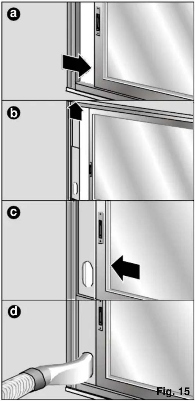
- The sliding window/balcony installation accessory can also be used (See "Description of accessories"), Fig. 15: a, b, c, d. This accessory can be used for both horizontal and vertical windows / balconies.
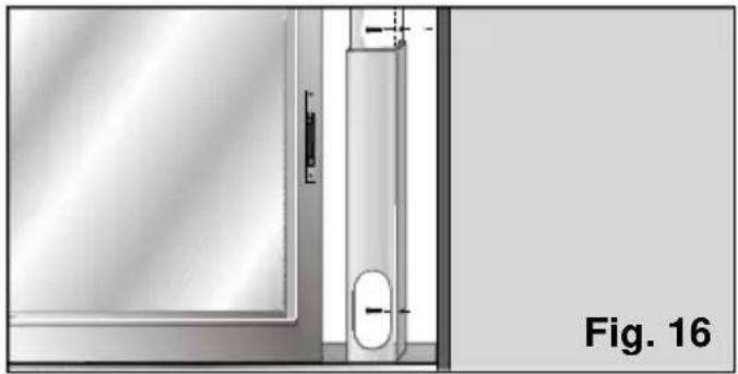
- The accessory has two holes on the side to fit it to the window / balcony with. The user can secure it to the frame or wall with two screws (not included with the accessory) to prevent it from moving or falling out of place, Fig. 16.
natural_image
Technical diagram showing a door frame and a vertical panel with measurement markings, labeled Fig. 16 (no text or symbols on the diagram itself)Permanent installation
Permanent installation is performed using the wall grommet / window grommet. See "Description of accessories".
☐ To expel hot air through the wall, it is necessary to make a hole in the wall and fit the wall grommet, Fig. 17.
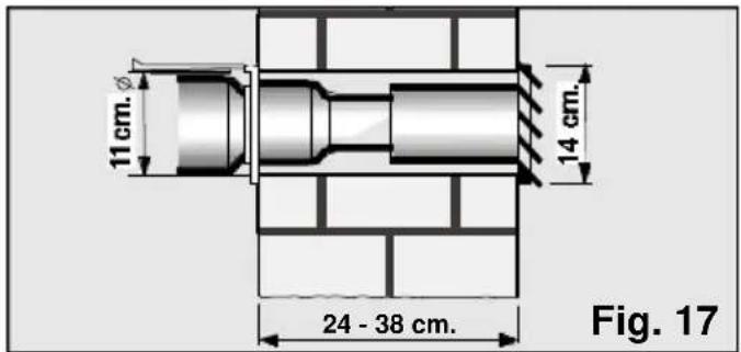
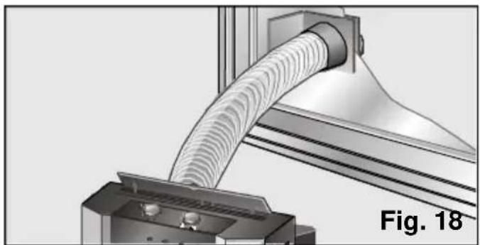
- Remove the diffusion sleeve and connect the air expulsion tube to the accessory. - If permanent installation is to be performed through the window, then it is only necessary to use the transparent end piece on the accessory. A 10.5-cm diameter hole needs to be cut in the glass, Fig. 18.
natural_image
Mechanical assembly showing a pipe passing through a housing component (no text or symbols visible)Notes
Do not extend the hot air expulsion tube more than necessary (maximum length; 140 cm).
Do not form sharp bends when positioning the tube, otherwise the correct expulsion of hot air may be impeded. This may cause a reduction in the cooling power and performance of the appliance.
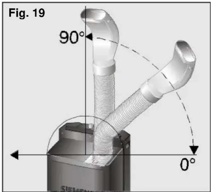
In order to achieve maximum cooling efficiency and minimum noise levels, the expulsion tube should be fitted above the total height of the appliance, Fig. 19.
Dehumidification
In position , the appliance reduces the humidity in the atmosphere.
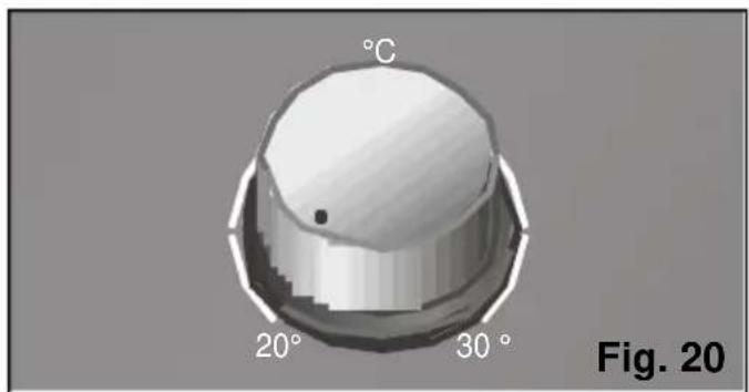
☐ Set the thermostat to its minimum temperature setting, Fig. 20.
natural_image
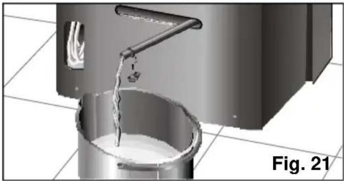
3D rendered mechanical knob with labeled degrees (20° and 30°) and a 'C' mark, no other text or symbols present.☐ Place a bowl at the drainage pipe outlet and remove the plug to collect the condensed water, Fig. 21.
natural_image
3D rendering of a mechanical component with liquid flowing through a bucket, labeled Fig. 21 (no text or symbols on the diagram itself)☐ Remove the diffusion duct and set the air expulsion tube to the position shown in figure 22.
☐ The expulsion tube may also be totally dismantled if desired.
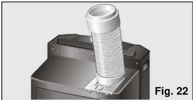
natural_image
3D rendering of a mechanical component with a coiled spring and housing (no text or symbols visible)☐ Lift the air director on the top of the appliance. This air director is not installed on the appliance on PA18100M models. See figures 25 and 26 in "Heating".
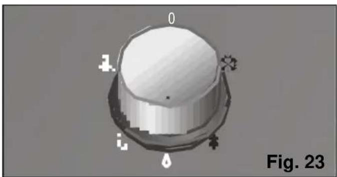
□ Select the dehumidification function,^ on the control knob, Fig. 23.
natural_image
3D rendered object resembling a dome or container with labeled parts (no readable text or symbols)Warning!
The amount of dehumidified water may reach a maximum of 36 litres in 24 hours, depending on ambient conditions. See "Technical Information".
Do not forget to replace the plug onto the water drainage pipe when you change function, otherwise the appliance will shed water when operated.
Remember that ambient temperature must be 18°C or higher in order for the appliance to work.
Air purification
The air entering the room (ventilation) is circulated through a purifying filter when the appliance is set to this function.
The appliance is fitted with a basic filter and a purifying filter for:
- Pollen, bacteria and dust.
☐ Put the air expulsion tube in the same position as for dehumidification.
☐ Lift the air director on the top of the appliance. This air director is not installed on the appliance on PA18100M models. See figures 25 and 26 in "Heating".
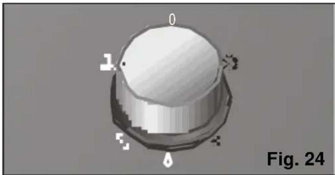
□ Select the purifying speed: maximum ✗ or silent ✗, Fig. 24.
natural_image
3D rendered mechanical knob or dial with labeled positions (0, 1, 2, 3) and a water droplet, no readable text or symbols beyond labels.□ When the appliance or the model is fitted with optional filters, we recommend that these be left on regardless of the function selected (air conditioning, dehumidification, air purification) in order to purify the air more effectively.
Heating (only on PA18100M)
When set to position , the appliance heats the air in the room until the temperature set by the user is reached. The air in the room is purified at the same time.
□ Plug the appliance into the mains electricity supply.
☐ Put the air expulsion tube in the same position as for dehumidification.
☐ This air director is not installed on the appliance on PA18100M models. The manufacturer recommends that an air director be previously installed in order to distribute the air flow better. The director is fitted as shown in the following figures.
natural_image
Diagram showing airflow or ventilation system with arrows pointing to a component (no text or symbols)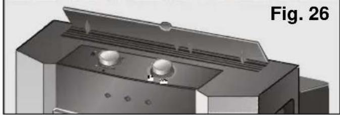
natural_image
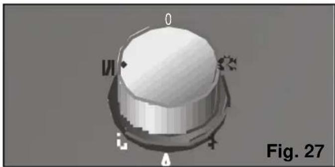
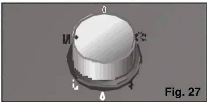
3D rendering of a mechanical device with ventilation grilles and control buttons (no text or symbols visible)□ Select the heating function, Fig. 27.
natural_image
3D rendered mechanical component with no visible text or symbols, labeled as Fig. 27 (no readable text or symbols on the component itself)☐ Set the thermostat to the desired temperature. When this temperature is reached, the appliance turns itself off automatically. It comes back on again when the temperature drops 2-3°C.
Warning!
Do not cover the air intakes or outlets on your appliance!
Cleaning the appliance
☐ For safety reasons, you should unplug the appliance from the mains electricity supply before cleaning.
☐ The appliance can be cleaned with a cloth or sponge, slightly warm water and a mild detergent.
□ Never use hot water (more than 40°C), bleach, benzene, petrol, acid, scouring pads, brushes or strong detergents. Prevent water from entering the appliance.
☐ Do not clean the appliance with a hose.
Cleaning and changing the purifying filters
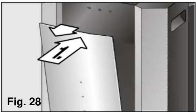
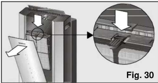
To change the purifying filter, it is first necessary to open the front flap on the appliance (it is not necessary to remove it). Pull the flap gently to do this. The flap can be opened up to the safety stop without risk of falling, Fig. 28.
natural_image
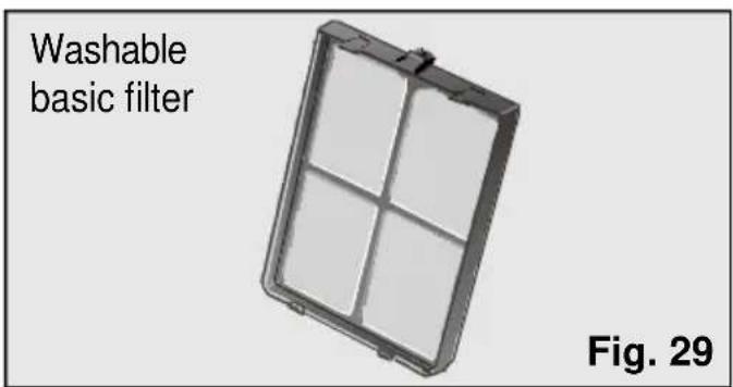
Diagram showing two arrows pointing to a document or panel, labeled 'Fig. 28' (no readable text or symbols)All models are fitted with a basic filter which needs to be cleaned regularly, Fig. 29. The filter is accessed by pressing the tab at the top and removing it from its housing, Fig. 30. The filter is cleaned under a cold tap, dried and replaced.
natural_image
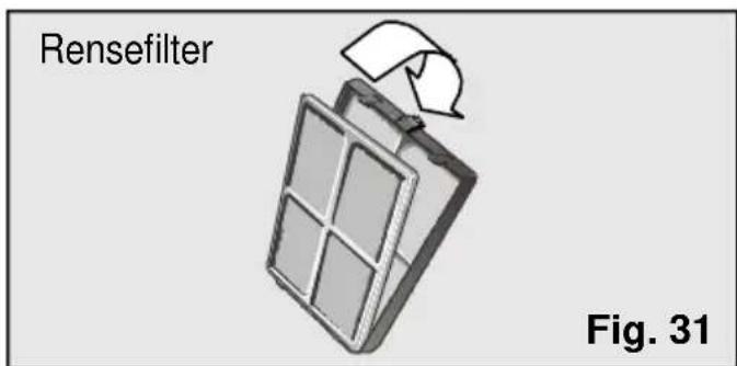
Technical diagram showing a mechanical assembly with an inset close-up of a structural detail (no text or symbols present)Apurifying filter is also fitted inside the basic filter on these models.
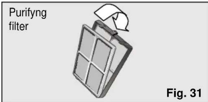
This purifying filter needs to be changed every year in order to remain operational.
(These accessories are available for purchase from the Manufacturer's Official Technical Service and authorised distributors). See "Description of accessories".
Installing the purifying filter:
□ Remove the basic filter from the appliance, Fig. 30.
□ Fit the purifying filter inside the basic filter as shown in Fig. 31.
☐ Install the assembly onto the appliance by lining the lower studs up with the slots on the front casing of the appliance and pressing the top clip in until it clicks into position. The assembly is fitted properly when it clicks into position.
□ Close the front flap.
☐ In order to maintain cooling power, only fit one set of filters onto the support.
Notes:
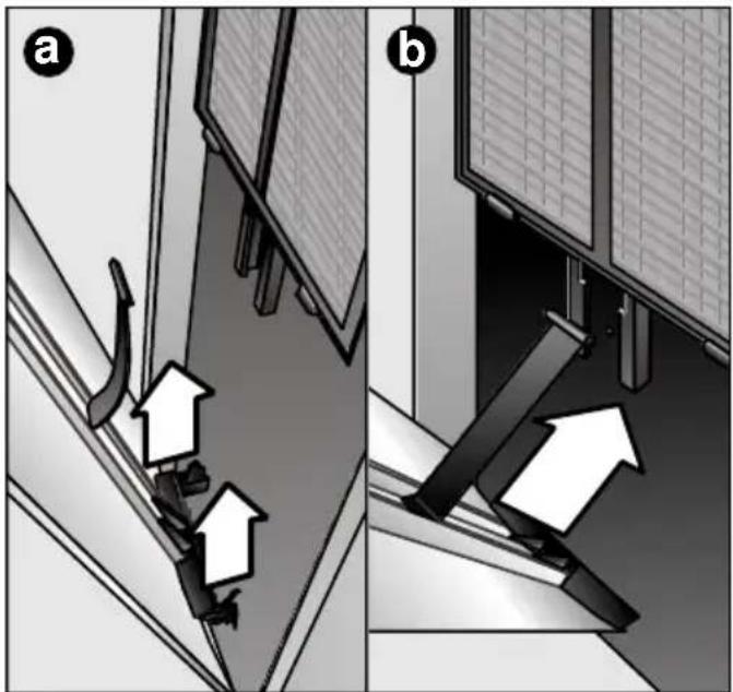
The flaps on these models are fitted with safety stops up to which point they can be opened without risk of the front flap falling and causing damage and/or injury. The flap on the appliance can be removed (firmly pull the flap towards you) to make it easier to clean and change the filters. Afterwards, or should for any reason the flap come out of its original housing, proceed as follows to fit it:
1° Lift the flap until it comes out of its lower supports, (Fig. 32: a).
2° Position the plastic leg in the front groove on the appliance (in T position) and slide it down to the safety stop, (Fig. 32: b).
3° fit the lower studs in the front stops on the appliance making sure that the plastic leg fitted in the previous step does not come out of position, (Fig. 32: c).
When finished, the user should make sure that the flap is fitted properly and does not fall when opened again. (The door opens up to the safety stop). If not fitted properly, repeat steps 1° and 2° again.
natural_image
Diagram showing two views (a and b) of a mechanical or architectural component with directional arrows indicating movement or force, no text or symbols present.
natural_image
Diagram showing a mechanical assembly with two downward arrows indicating motion or force, labeled 'Fig. 32' (no text or symbols on the diagram itself)Storage requirements
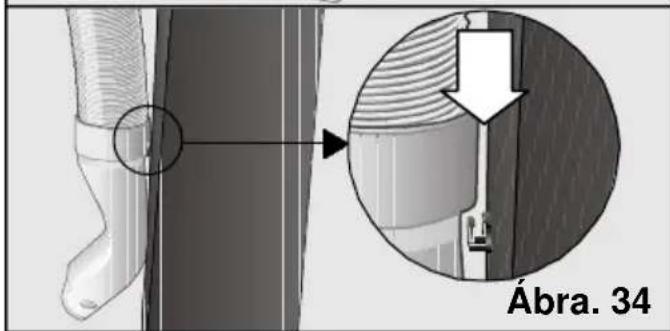
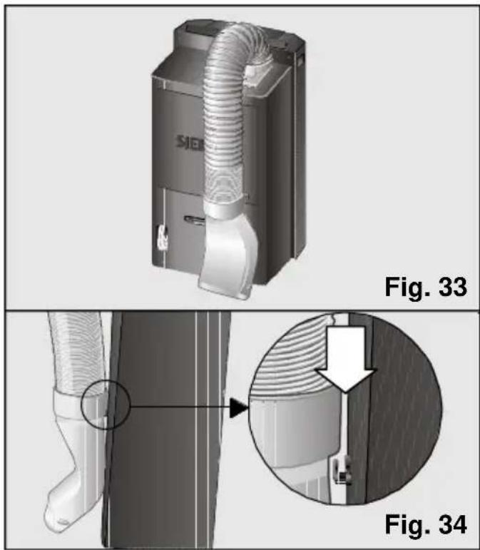
When the appliance is out of use for a long period, set the expulsion tube to parking position so that the appliance takes up as little space as possible.
☐ To do this, bend the tube towards the back of the appliance and secure it with the diffusion hook, Figs. 33 and 34.
Prior to use at change of season
□ Clean the air filter.
□ Clean the casing and the grilles if necessary.
General requirements for operation
What to do if...
... the appliance does not work ...
☐ Check that it is plugged in properly.
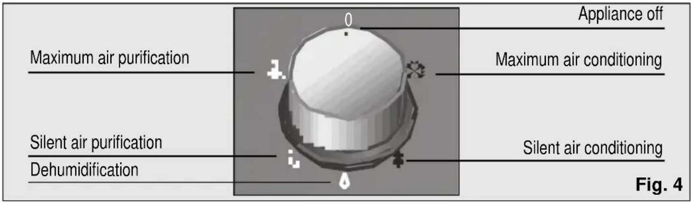
□ Make sure that the control knob is not set to off ●.
☐ Check that the mains electricity supply is working. Check the fuse box.
☐ Set the thermostat to a lower temperature.
... the appliance does not work and the light indicating that the condensed water tank is full is on ...
☐ Set the appliance on a flat surface. If the light does not go out, empty the internal water tank. (See instructions in "Cooling").
... the appliance does not reduce room temperature sufficiently ...
☐ Check the joins on the hot air expulsion tube.
☐ Make sure that the expulsion tube is not too bent and that it is not extended to more than 140 cm.
□ Make sure that the plug is fitted on the drainage water pipe.
☐ Fit the suction pad to close the window as far as possible.
☐ Lower blinds to reduce direct sunlight.
... there is water on the control panel grille or on the basic filter housing ...
☐ There is no cause for concern. This is normal.
Noise
... the appliance makes a lot of noise ...
Some noise is normal and other types of noise can be solved easily. You need to be able to distinguish between these types of noise:
Perfectly normal noise
☐ The sound of water flowing in cycles is due to the pump, which circulates the water to enhance the power of the appliance.
☐ A dull, humming sound is inevitable due to the compressor.
☐ A faint, whistling sound is due to the refrigerant passing through the thinner pipes on the appliance when the compressor starts up.
☐ A short clicking sound is produced when the pump connects and disconnects or when the regulator connects or disconnects the electronics system.
Easy-to-solve noises
□ Make sure that the air expulsion tube and the diffusion and collection sleeves are fitted properly onto the appliance.
□ Make sure that the air intakes and outlets on the appliance are free of obstacles.
☐ Make sure that the appliance is not in direct contact with furniture or other appliances. The air output may be flowing directly onto these and thereby increasing the noise level.
Any other type of fault or repair work should be dealt with by a specialised Technician. Get in touch with your authorised dealer, customer service or the Technical Service Network.
Technical service
Should your appliance fail to work properly and all the instructions for use and installation (especially the section headed
"Requirements....") have been carefully observed, then remember that our Technical Service Network is at your full disposal.
When contacting the Technical Service, quote the model code (E-NR) and the appliance's factory number (FD). This information can be found on characteristics plate, Fig. 2.
Warranty
The conditions of warranty depend on the relevant Supplier in a particular country. Contact the establishment where you purchased your appliance for more information and quote the appliance model and factory number. The receipt of purchase for the appliance must be produced prior to any work carried out under warranty.
Technical Information
| Model PA19000M PA18100M | ||
| Consumption at maximum power (W)* 975 975 | ||
| Cooling capacity (W)* 1900 1800 | ||
| Dehumidification capacity (l./day) 36 36 | ||
| Power in heating mode (W) – 1800 | ||
| Fuse (A) | 10 10 | |
| Energy efficiency (letter) | D | D |
| Working range | ||
| - Cooling (min./max. °C) | 20 – 35 | 20 – 35 |
| - Dehumidification (min./max. °C) | 18 – 35 | 18 – 35 |
| (*) per EN14511 | ||
Sommaire
natural_image
Symbolic representation of a trash bin crossed with a diagonal line, no text or labels presentnatural_image
3D diagram of a kitchen appliance with a handle and arrow, labeled Fig. 1 (no text or symbols on the main diagram)Conditions de transport
natural_image
3D rendering of a mechanical component with a bucket and pipe, labeled Fig. 7 (no text or symbols on the diagram itself)Mode d'Emploi
Climatisation
natural_image
3D rendered mechanical component with 20° and 30° angular features, labeled Fig. 9 (no text or symbols on the object itself)Mode d'Emploi
natural_image
Close-up of a mechanical component with two white arrows pointing to features, labeled 'Fig. 12' (no text or symbols on the object itself)natural_image
Illustration of a hand holding a flexible hose to connect a window frame (no text or symbols visible)Mode d'Emploi
natural_image
Technical diagram showing a door frame with a door and a doorbell, labeled Fig. 16 (no text or symbols on the diagram itself)Installation fixe
natural_image
Mechanical assembly showing a pipe passing through a housing component (no text or symbols visible)Remarques:
natural_image
3D rendered mechanical component with labeled degrees (20° and 30°) and a 'C' mark, no readable text or symbols beyond labels.natural_image
3D rendering of a mechanical device with a bucket and water pipe, labeled Fig. 21 (no text or symbols on the diagram itself)natural_image
3D rendering of a mechanical component with a coiled spring and mounting base, labeled Fig. 22 (no text or symbols on the object itself)natural_image
3D rendered mechanical component with no visible text or symbolsAttention!
natural_image
3D rendered object resembling a dome or container with labeled points (0, 1, 2, 3) and a water droplet, no readable text or symbols beyond labels.natural_image
Diagram showing airflow or ventilation between a fan blade and a vent, with arrows indicating direction (no text or symbols)
natural_image
3D rendering of a mechanical component with two circular features and a lid, labeled Fig. 26 (no text or symbols on the object itself)natural_image
3D rendered mechanical component with labeled parts (M, O, L) and a downward arrow, no readable text or symbols beyond labelsnatural_image
Diagram showing two white arrows pointing downward on a wall, labeled 'Fig. 28' (no text or symbols on the diagram itself)natural_image
Diagram showing a device interior with an arrow pointing to a component, and a magnified view of a structural detail labeled Fig. 30 (no text or symbols on the diagram itself)natural_image
Diagram showing two views (a and b) of a window with mechanical components, no text or symbols present.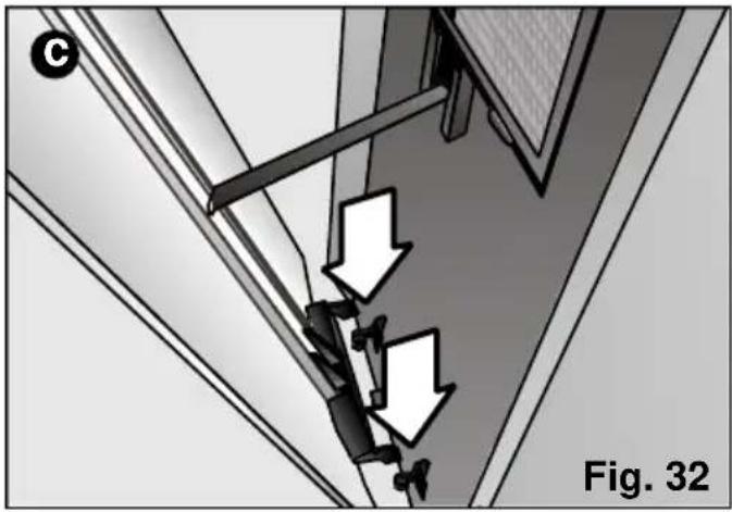
natural_image
Diagram showing mechanical components with arrows indicating downward motion, labeled 'Fig. 32' (no text or symbols on diagram itself)natural_image
3D rendering of a Siemens industrial air duct system (no text or symbols visible)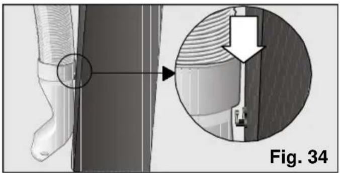
natural_image
Technical diagram showing a mechanical component with an inset close-up of a detail (no text or symbols present)natural_image
3D diagram of a kitchen appliance with a handle and arrow indicating a component, labeled Fig. 1 (no text or symbols on the main diagram)natural_image
3D rendering of a mechanical device pouring liquid into a bucket, labeled Fig. 7 (no text or symbols on the diagram itself)natural_image
3D rendered object with labeled parts (0, 1, 2, 3, 4) and no visible text or symbols on the object itselfnatural_image
3D rendered mechanical component with labeled degrees (20° and 30°) and a 'C' mark, no readable text or symbols beyond labels.natural_image
Mechanical component diagram showing a base with two upward-pointing arrows indicating motion or assembly (no text or symbols present)natural_image
Illustration of a hand holding a flexible hose to install a door frame, labeled Fig. 14 (no text or symbols on the diagram itself)natural_image
Technical diagram showing a door frame and a vertical panel with a minus symbol, labeled Fig. 16 (no text or symbols on the diagram itself)Instalación fija
natural_image
Mechanical assembly showing a pipe passing through a housing component (no text or symbols visible)Notas:
natural_image
3D rendered mechanical component with labeled degrees (20° and 30°) and a 'C' mark, no readable text or symbols beyond labels.natural_image
3D rendering of a mechanical component with liquid flowing through a bucket, labeled Fig. 21 (no text or symbols on the diagram itself)natural_image
3D rendering of a mechanical component with a coiled spring and housing (no text or symbols visible)natural_image
3D rendered mechanical component with labeled parts (no readable text or symbols)¡Atención!
natural_image
3D rendered mechanical component with no visible text or symbols, labeled 'Fig. 24' at bottom right (no readable text or symbols on the component itself)natural_image
Diagram showing airflow or ventilation system with arrows pointing to a component (no text or symbols)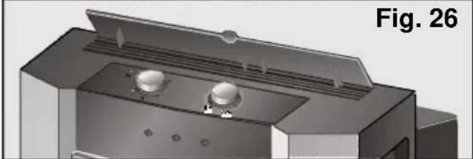
natural_image
3D rendering of a printer or printer casing with two circular components and ventilation grilles (no text or symbols visible)natural_image
3D rendered mechanical component with no visible text or symbols, labeled 'Fig. 27' at bottom right (no readable text or symbols on the object itself)natural_image
Diagram showing two overlapping paper sheets with arrows pointing downward, labeled Fig. 28 (no text or symbols on the diagram itself)natural_image
Technical diagram showing a mechanical assembly with an inset close-up of a structural detail (no text or symbols present)natural_image
Diagram showing two views (a and b) of a window with ventilation ducts and airflow arrows, no text or symbols present.
natural_image
Diagram showing a mechanical assembly with two downward arrows indicating motion or force, labeled 'Fig. 32' (no text or symbols on the diagram itself)natural_image
3D rendering of a kitchen appliance with a handle and arrow indicator, labeled Fig. 1 (no text or symbols on the main subject)natural_image
3D rendering of a metal bucket pouring liquid into a container, with no visible text or symbolsInstruções de Uso
Climatização
natural_image
3D rendered mechanical component with no visible text or symbols, labeled 'Fig. 8' at bottom right (no readable text or symbols on the object itself)natural_image
3D rendered mechanical component with labeled degrees (20° and 30°) and a '°C' mark, no readable text or symbols beyond labels.Instruções de Uso
natural_image
Close-up of a mechanical component with two upward-pointing arrows indicating motion or assembly (no text or symbols)natural_image
Illustration of a hand holding a flexible hose to connect a window frame (no text or symbols)Instruções de Uso
natural_image
Technical diagram showing a door frame with a door and a doorbell, labeled Fig. 16 (no text or symbols on the diagram itself)Instalação fixa
natural_image
Mechanical assembly showing a pipe passing through a housing with a base device, labeled Fig. 18 (no text or symbols on the diagram itself)Notas:
natural_image
3D rendered mechanical knob with labeled degrees (20° and 30°) and a 'C' mark, no readable text or symbols beyond labelsnatural_image
3D rendering of a mechanical device pouring liquid into a bucket, labeled Fig. 21 (no text or symbols on the diagram itself)natural_image
3D rendering of a mechanical component with a coiled spring and mounting base, labeled Fig. 22 (no text or symbols on the object itself)natural_image
3D rendered mechanical component with no visible text or symbols, labeled as Fig. 23 (no readable text or symbols on the component itself)Atenção!
natural_image
3D rendered mechanical component with labeled parts (no text or symbols on the object itself)natural_image
Diagram showing airflow or fluid flow between a panel and a device, labeled Fig. 25 (no text or symbols on diagram itself)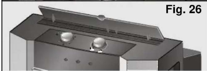
natural_image
3D rendering of a mechanical component with two circular features and a lid, labeled Fig. 26 (no text or symbols on the diagram itself)natural_image
3D rendered mechanical component with no visible text or symbols, labeled 'Fig. 27' at bottom right (no readable text or symbols on the object itself)natural_image
Diagram showing two arrows pointing to a document or paper, labeled 'Fig. 28' (no readable text or symbols)natural_image
Technical illustration of a mechanical device with an inset close-up showing internal components (no text or symbols)natural_image
Diagram showing two views (a and b) of a window with ventilation grilles and a scroll, no text or symbols present.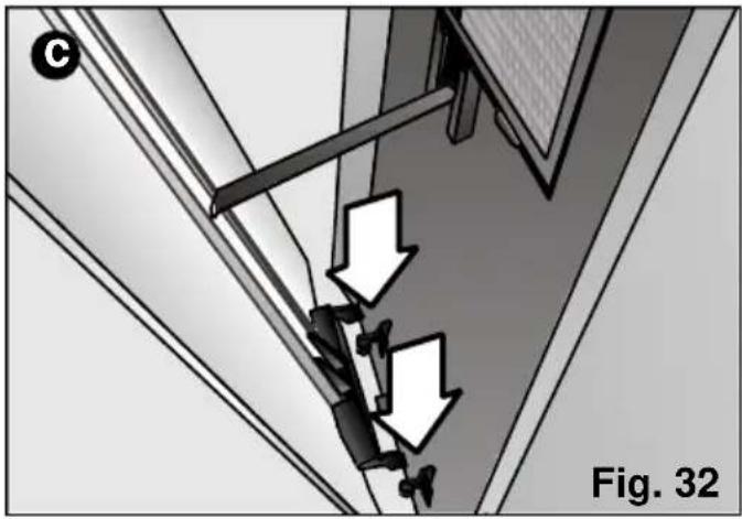
natural_image
Diagram showing a mechanical assembly with two downward arrows indicating motion or force, labeled 'Fig. 32' (no text or symbols on the diagram itself)natural_image
3D rendering of a Siemens industrial air duct system (no text or symbols visible)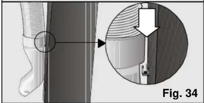
natural_image
Technical diagram showing a mechanical component with an inset close-up of a detail (no text or symbols present)natural_image
3D diagram of a kitchen appliance with a handle and arrow indicating a component, labeled Fig. 1 (no text or symbols on the main structure)natural_image
3D rendering of a mechanical device pouring liquid into a bucket, labeled Fig. 7 (no text or symbols on the diagram itself)natural_image
3D rendered mechanical component with labeled parts (no text or symbols on the object itself)natural_image
3D rendered mechanical component with labeled degrees (20° and 30°) and a 'C' mark, no readable text or symbols beyond labels.natural_image
Diagram of a mechanical component with two upward-pointing arrows indicating motion or assembly (no text or symbols present)natural_image
Diagram of a cable being inserted into a window frame, labeled Fig. 14 (no text or symbols on the diagram itself)natural_image
Architectural detail showing a window with a vertical panel and a door, labeled Fig. 16 (no text or symbols on the diagram itself)Vaste installatie
natural_image
Mechanical assembly showing a coiled pipe being inserted into a housing component, labeled Fig. 18 (no text or symbols on the diagram itself)Opmerkingen:
natural_image
3D rendered mechanical knob with temperature and angle labels (20°, 30°) and 'Fig. 20' at bottom right, no other text or symbols present.natural_image
3D rendering of a mechanical component with liquid flowing through a bucket, labeled Fig. 21 (no text or symbols on the diagram itself)natural_image
3D rendering of a mechanical component with a coiled spring and housing (no text or symbols visible)natural_image
3D rendered object with labeled points (0, 1, 2, 3, 4) and no visible text or symbols on the object itselfVerwarming (alleen in model PA18100M)
natural_image
3D rendered mechanical knob or dial with labeled ports (no text or symbols on the dial itself)natural_image
Diagram showing two arrows pointing at a white panel, labeled 'Fig. 28' (no text or symbols on the diagram itself)
natural_image
Technical diagram showing a mechanical assembly with an inset close-up of a structural detail (no text or symbols present)natural_image
Diagram showing two views (a and b) of a mechanical assembly with arrows indicating motion or force direction, no text or symbols present.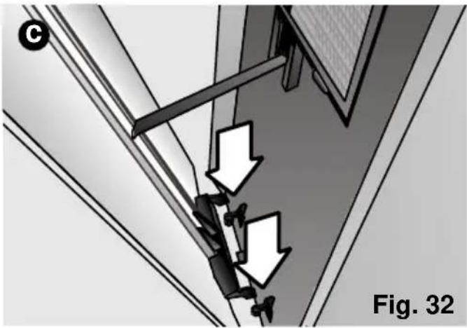
natural_image
Diagram showing a mechanical assembly with two downward arrows indicating motion or force, labeled Fig. 32 (no text or symbols on the diagram itself)natural_image
3D rendering of a Siemens industrial device with coiled duct and housing (no text or symbols visible)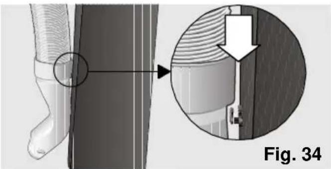
natural_image
Technical illustration of a mechanical component with an inset magnified view showing a detail (no text or symbols present)natural_image
3D diagram of a kitchen appliance with a handle and arrow indicating a component, labeled Fig. 1 (no text or symbols on the main structure)natural_image
3D rendering of a metal bucket pouring liquid into a container, with no visible text or symbolsIstruzioni d'uso
Climatizzazione
natural_image
3D rendered mechanical component with labeled parts (no text or symbols on the object itself)natural_image
3D rendered mechanical component with labeled degrees (20° and 30°) and a 'C' mark, no readable text or symbols beyond labels.Istruzioni d'uso
natural_image
Close-up of a mechanical component with two white arrows pointing to features, labeled 'Fig. 12' (no readable text or symbols beyond label)natural_image
Diagram of a pipe being inserted into a window frame, labeled Fig. 14 (no text or symbols on the diagram itself)Istruzioni d'uso
natural_image
Technical diagram showing a door frame with a door and a doorbell, labeled Fig. 16 (no text or symbols on the diagram itself)Installazione fissa
natural_image
Diagram of a mechanical device emitting a coiled cable or fiber, labeled 'Fig. 18' (no text or symbols on the diagram itself)Note:
natural_image
3D rendered mechanical component with labeled degrees (20° and 30°) and a 'C' mark, no readable text or symbols beyond labels.natural_image
3D rendering of a mechanical device pouring liquid into a bucket, labeled Fig. 21 (no text or symbols on the diagram itself)natural_image
3D rendering of a mechanical component with a coiled spring and mounting base, labeled Fig. 22 (no text or symbols on the object itself)natural_image
3D rendered mechanical component with no visible text or symbols, labeled 'Fig. 23' at bottom right (no readable text or symbols on the object itself)Attenzione!
natural_image
3D rendered mechanical component with labeled parts (0, 1, 2, 3, 4) and no visible text or symbols on the object itself.natural_image
Diagram showing a component with two downward arrows pointing to a panel, labeled Fig. 25 (no text or symbols on the diagram itself)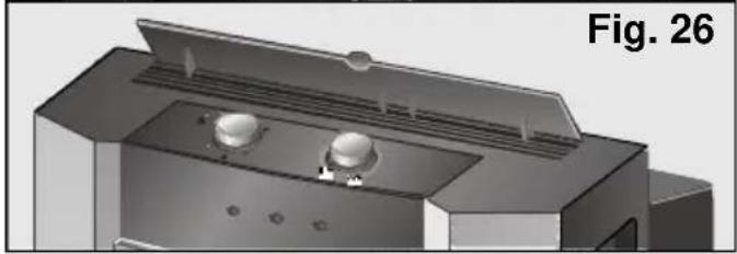
natural_image
3D rendering of a mechanical device with two circular components and a lid, labeled Fig. 26 (no text or symbols on the device itself)natural_image
3D rendered mechanical component with labeled parts (no readable text or symbols)natural_image
Diagram showing two overlapping documents with arrows pointing to them, labeled 'Fig. 28' (no readable text or symbols)natural_image
Technical illustration of a mechanical device with an inset close-up showing a detail of a structural detail (no text or symbols present)natural_image
Diagram showing two views (a and b) of a window with ventilation ducts and airflow arrows, no text or symbols present.
natural_image
Diagram showing mechanical components with arrows indicating downward motion, labeled 'Fig. 32' (no text or symbols on diagram itself)natural_image
Symbol of a trash bin crossed with two crossed lines, representing waste sorting or restriction (no text present)
Så sparar Du energi
natural_image
3D rendering of a kitchen appliance with a handle and arrow pointing to a component, labeled 'Bild. 1' (no text on the appliance itself)natural_image
3D rendering of a metal bucket pouring liquid into a cylindrical container, with no visible text or symbolsnatural_image
3D rendered mechanical knob with temperature and angle labels (20°, 30°) and 'Bild 9' identifier, no other text or symbols present.natural_image
Close-up of a mechanical component with two white arrows pointing upward, labeled 'Bild. 12' (no other text or symbols)natural_image
Illustration of a hand holding a coiled cable attached to a window frame, labeled 'Bild. 14' (no other text or symbols)natural_image
Architectural detail showing a window with a door and a cylindrical component, labeled 'Bild. 16' (no other text or symbols)Fast installation
natural_image
Mechanical assembly showing a pipe passing through a housing component (no text or symbols visible)Observationer:
natural_image
3D rendered mechanical knob with temperature and angle annotations (no text or symbols on the knob itself)natural_image
3D rendering of a mechanical component pouring liquid into a cylindrical tank, with no visible text or symbols.natural_image
3D rendered mechanical component with coiled spring and mounting base (no text or symbols)natural_image
3D rendered object with a dome-like top and surrounding small protrusions, labeled 'Bild. 24' at bottom (no other text or symbols)natural_image
3D rendered mechanical component with no visible text or symbolsnatural_image
Illustration of a door with two arrows pointing to a white sheet, labeled 'Bild. 28' (no other text or symbols)natural_image
Technical diagram showing a mechanical assembly with an inset close-up of a structural detail (no text or symbols present)natural_image
Diagram showing two scenarios (a and b) of a window with a cat, arrows indicating movement, and a tool inserted into the interior (no text or symbols present)
natural_image
Diagram showing a mechanical assembly with three downward arrows indicating motion or force directions, labeled 'Bild. 32' (no text or symbols on the diagram itself)natural_image
Symbol of a trash bin crossed with diagonal lines, representing waste sorting or restriction (no text present)
Råd om energisparing
natural_image
3D diagram of a kitchen appliance with a handle and arrow pointing to a component, labeled Fig. 1 (no text or symbols on the main diagram)natural_image
3D rendering of a mechanical component pouring liquid into a bucket, with no visible text or symbolsBruksanvisning
Klimatisering
natural_image
3D rendered object resembling a dome or container with labeled parts (no text or symbols on the object itself)natural_image
3D rendered mechanical component with labeled degrees (20° and 30°) and a 'C' mark, no readable text or symbols beyond labels.Bruksanvisning
natural_image
Close-up of a mechanical component with two white arrows pointing to features, labeled 'Fig. 12' (no text or symbols on the object itself)Når slangesettet er montert på anlegget, settes sprededysen på. Fig. 10.
natural_image
Illustration of a hand holding a flexible hose to install a door frame, labeled Fig. 14 (no text or symbols on the diagram itself)Bruksanvisning
natural_image
Technical diagram showing a door frame with a door and a doorbell, labeled Fig. 16 (no text or symbols on the diagram itself)Fast installasjon
natural_image
Mechanical assembly showing a coiled pipe being inserted into a housing (no text or symbols visible)Noter:
Bruk ikke unødvendig lang utluftingsslange for varmluften (maksimal lengde 140 cm).
Bruksanvisning
natural_image
3D rendered mechanical component with labeled degrees (20° and 30°) and a 'C' mark, no readable text or symbols beyond labels.natural_image
3D rendering of a mechanical device pouring liquid into a bucket, labeled Fig. 21 (no text or symbols on the diagram itself)natural_image
3D rendered mechanical component with coiled spring and mounting base, labeled Fig. 22 (no text or symbols on the component itself)natural_image
3D rendered mechanical component with no visible text or symbols, labeled 'Fig. 23' at bottom right (no readable text or symbols on the object itself)Bemerk!
natural_image
3D rendered mechanical component with labeled parts (0, 1, 2, 3, 4) and no visible text or symbols on the object itself.natural_image
Diagram showing airflow or ventilation system with arrows pointing to a component (no text or symbols)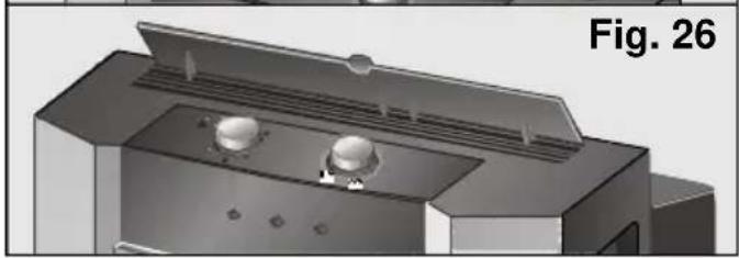
natural_image
3D rendering of a mechanical device with two circular components and ventilation grilles (no text or symbols visible)□ Velg varmefunksjon, Fig. 27.
natural_image
3D rendered mechanical component with labeled parts (no readable text or symbols)natural_image
Diagram showing two overlapping paper sheets with arrows pointing upward, labeled 'Fig. 28' (no text or symbols on the diagram itself)natural_image
Technical illustration of a mechanical device with an inset close-up showing structural details (no text or symbols)Disse modellene har dessuten i tillegg et rensefilter som ligger inni standardfilteret.
natural_image
Diagram showing two views (a and b) of a window with mechanical components, no text or symbols present.
natural_image
Diagram showing mechanical components with arrows indicating downward motion, labeled 'Fig. 32' (no text or symbols on diagram itself)Lagringsvilkår
natural_image
3D rendering of a Siemens air duct controller device (no text or symbols visible)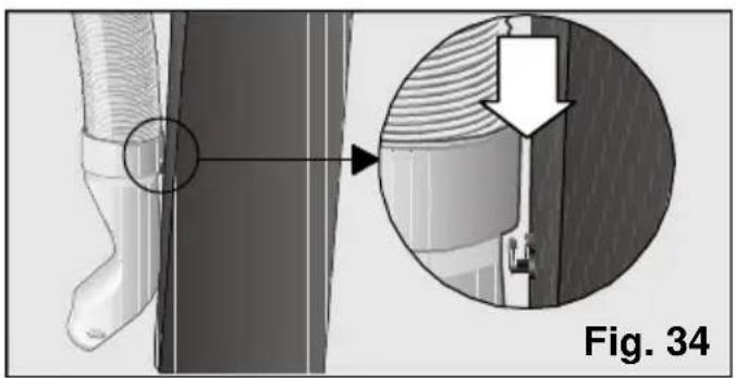
natural_image
Technical diagram showing a mechanical component with an inset close-up view labeled Fig. 34 (no text or symbols on the diagram itself)natural_image
Symbol of a trash bin crossed with no text or labels
natural_image
3D diagram of a kitchen appliance with a handle and arrow, labeled 'Ábra. 1' (no other text or symbols)A készülék leírása
natural_image
3D rendering of a metal container pouring liquid into a cylindrical tank, with no visible text or symbols on the diagram itself.Használati útmutató
A légkondicionálás
natural_image
Illustration of a hand holding a cable or wire attached to a window frame, with no visible text or symbols.natural_image
Diagram of a door with an arrow pointing to the left side of a window (no text or symbols present)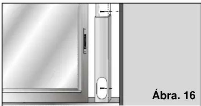
natural_image
Architectural detail showing a window with a door and vertical panel, labeled 'Ábra. 16' (no other text or symbols)Használati útmutató
Fix rögzítés
natural_image
Close-up of a mechanical device with coiled tubing and a labeled section (no readable text or symbols)Megjegyzés:
natural_image
3D rendering of a mechanical device with a water pipe inserted into a container, labeled 'Ábra. 21' (no other text or symbols)natural_image
3D rendering of a mechanical component with a coiled spring and mounting base (no text or symbols visible)natural_image
3D rendered object resembling a dome or container with labeled points (0, 1, 2, 3) and a small symbol, no readable text or symbols beyond labels.Figyelem!
natural_image
3D rendered mechanical component with no visible text or symbolsnatural_image
Diagram showing two views (a and b) of a window or door assembly with directional arrows indicating movement or force, no text or symbols present.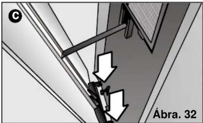
Tárolási feltételek
natural_image
3D rendering of a Siemens industrial device with coiled tubing and a labeled section (no readable text or symbols on the device itself)