
AEA09BE - Air-conditioner SHARP - Free user manual and instructions
Find the device manual for free AEA09BE SHARP in PDF.
| Product Type | Split air conditioner |
| Brand | Sharp |
| Model | AEA09BE |
| Power Supply | 230 V ~ 50 Hz |
| Operating Modes | Auto, Cool (cooling), Dry (dehumidification) |
| Temperature Range (Cool) | 18 °C to 32 °C |
| Fan Speed | Auto, Soft, High, Low |
| Air Flow Direction | Vertical (motorized) and Horizontal (manual) |
| Timers | Off after 1 hour, programmable timer (0.5 to 12 h) |
| Remote Control | Yes, with LCD display and AAA (R03) batteries |
| Air Filter | Washable, clean every 2 weeks |
| Air Purifying Filter (optional) | Apatite antibacterial filter, replace every 3 to 6 months |
| Maintenance | Clean filters with vacuum or warm water, dry in shade |
| Safety - Grounding | Mandatory, do not connect to gas or water pipe |
| Safety - Power Failure | Unit restarts automatically after a power failure (except timer) |
| Safety - Protection | Leakage circuit breaker recommended; do not use with wet hands |
| Installation | Entrust to a qualified professional |
| Repairability | Do not disassemble yourself; contact after-sales service |
| Indoor Unit Dimensions | Not available in the manual |
| Weight | Not available |
Frequently Asked Questions - AEA09BE SHARP
User questions about AEA09BE SHARP
0 question about this device. Answer the ones you know or ask your own.
Ask a new question about this device
Download the instructions for your Air-conditioner in PDF format for free! Find your manual AEA09BE - SHARP and take your electronic device back in hand. On this page are published all the documents necessary for the use of your device. AEA09BE by SHARP.
USER MANUAL AEA09BE SHARP
natural_image
Illustration of a mobile phone emitting a light beam into a rectangular air conditioner (no text or symbols)INDOOR UNIT
ZIMMERGERÄT
UNIT INTERIEURE
UNIDAD INTERIOR
UNITA' INTERNA
UNIDADE INTERIOR
ΕΣΩΤΕΡΙΚΗ ΣΥΣΚΕΥΗ
BINNEN-UNIT
İÇ ÜNİTE
ВНУТРЕННИЙ БЛОК
AY-A07BE
AY-A09BE
AY-A12BE
AH-A07BE
AH-A09BE
AH-A12BE
OUTDOOR UNIT
AUSSENGERÄT
UNIT EXTERIEURE
UNIDAD EXTERIOR
UNITA' ESTERNA
UNIDADE EXTERIOR
ΕΞΩΤΕΡΙΚΗ ΣΥΣΚΕΥΗ
BUITEN-UNIT
DIŞ ÜNİTE
НАРУЖНИЙ БЛОК
AE-A07BE
AE-A09BE
AE-A12BE
AU-A07BE
AU-A09BE
AU-A12BE
香港電器安全規格
(國際電工委員會規格適合)
AY-A07BE AY-A09BE AY-A12BE AH-A07BE AH-A09BE AH-A12BE
SPLIT TYPE
ROOM AIR CONDITIONER
ZWEITEILIGES
KLIMAGERÄT
CLIMATISEUR INDIVIDUEL
EN DEUX PARTIES
MANUAL DE INSTRUÇÕES
Thank you for purchasing a SHARP air conditioner. Please read this manual carefully before operating the product.
CONTENTS
- PRECAUTIONS ......E-1
• ADDITIONAL NOTES ON OPERATION .....E-3
• TIPS ON SAVING ENERGY .....E-3 -
PART NAMES....E-4
• USING THE REMOTE CONTROL .....E-6
• BASIC OPERATION .....E-8
• ADJUSTING THE AIR FLOW DIRECTION .E-10 -
ONE-HOUR OFF TIMER ...... E-11
• TIMER OPERATION..... E-12 - AUXILIARY MODE ...... E-14
• OPTION KIT..... E-14 - MAINTENANCE ...... E-15
- BEFORE CALLING FOR SERVICE ... E-16
PRECAUTIONS
WARNINGS FOR USE
1 Do not pull or deform the power supply cord. Pulling and misuse of the power supply cord can result in damage to the unit and cause electrical shock.
2 Be careful not to expose your body directly to the outlet air for a long time. It may affect your physical conditions.
3 When using the air conditioner for infants, children, elderly, bedridden, or disabled people make sure the room temperature is suitable for those in the room.
4 Never insert objects into the unit. Inserting objects can result in injury due to the high speed rotation of internal fans.
5 Ground the air conditioner without fail. Do not connect the grounding wire to gas pipe, water pipe, lightning rod or telephone grounding wire. Incomplete grounding may cause electric shock.
6 If anything is abnormal with the air conditioner (ex. a burning smell), stop the operation immediately and turn the circuit breaker OFF.
7 Follow local rules and regulations for power supply cord cabling. Improper cable connection can cause the power supply cord, plug and the electrical outlet to overheat and cause fire.
8 Use only the manufacture-specified power cord for replacement. Replacement should be performed by a qualified technician or a service person.
WARNINGS FOR INSTALLATION / REMOVAL / REPAIR
- Do not attempt to install/remove/repair the unit by yourself. Incorrect work will cause electric shock, water leak, fire etc. Consult your dealer or other qualified service personnel for the installation/removal/repair of the unit.

This equipment complies with the requirements of Directives 89/336/EEC and 73/23/EEC as amended by 93/68/EEC.
PRECAUTIONS
CAUTIONS FOR USE
1 Open a window or door periodically to ventilate the room, especially when using gas appliances. Insufficient ventilation may cause oxygen shortage.
2 Do not operate the buttons with wet hand. It may cause electric shock.
3 For safety, turn the circuit breaker off when not using the unit for an extended period of time.
4 Check the outdoor unit mounting rack periodically for wear and to make sure it is firmly in place.
5 Do not put anything on the outdoor unit nor step on it. The object or the person may fall down or drop, causing injury.
6 This unit is designed for residential use. Do not use for other applications such as in a kennel or greenhouse to raise animals or grow plants.
7 Do not place a vessel with water on the unit. If water penetrates into the unit, electrical insulations may deteriorate and cause electric shock.
8 Do not block the air inlets nor outlets of the unit. It may cause insufficient performance or troubles.
9 Be sure to stop the operation and turn the circuit breaker off before performing any maintenance or cleaning. A fan is rotating inside the unit and you may get injured.
10 Do not splash or pour water directly on the unit. Water can cause electrical shock or equipment damage.
11 This appliance is not intended for use by young children or infirm persons without supervision.
Young children should be supervised to ensure that they do not play with the appliance.
CAUTIONS FOR LOCATION / INSTALLATION
- Make sure to connect the air conditioner to power supply of the rated voltage and frequency.
Use of a power supply with improper voltage and frequency can result in equipment damage and possible fire. - Do not install the unit in a place where inflammable gas may leak. It may cause fire. Install the unit in a place with minimal dust, fumes and moisture in the air.
- Arrange the drain hose to ensure smooth drainage. Insufficient drainage may cause wetting of the room, furniture etc.
- Make sure a leak breaker or a circuit breaker is installed, depending on the installation location, to avoid electrical shock.
ADDITIONAL NOTES ON OPERATION
D.B. = Dry-bulb W.B. = Wet-bulb
• The built-in protective device may prevent the unit from operating when used out of this range.
- Condensation may form on the air outlet if the unit operates continuously in the COOL or DRY mode when humidity is over 80 percent.
WHEN POWER FAILURE OCCURS
This air conditioner has a memory function to store settings when a power failure occurs.
After power recovery, the unit will automatically re-start in the same settings which were active before the power failure, except for timer settings.
If the timers were set before a power failure, they will need to be re-set after power recovery.
NOTES FOR MODELS AY-A07BE/AY-A09BE/AY-A12BE
PREHEATING FUNCTION
In the HEAT operation, the indoor fan may not start for two to five minutes after the unit is turned on to prevent cold air from blowing out of the unit.
DE-ICING FUNCTION
- When ice forms on the heat exchanger in the outdoor unit during the HEAT operation, an automatic de-icer provides heat for about 5 to 10 minutes to remove the ice. During de-icing, the inside and outside fans stop operating.
- After de-icing is completed, the unit automatically resumes operation in the HEAT mode.
HEATING EFFICIENCY
- The unit employs a heat pump that draws heat from the outside air and releases it into the room. The outside air temperature therefore greatly affects the heating efficiency.
- If the heating efficiency is reduced due to low outside temperatures, use an additional heater.
- It takes time to warm up and heat the entire room because of the forced air circulation system.
TIPS ON SAVING ENERGY
Below are some simple ways to save energy when you use your air conditioner.
SET THE CORRECT TEMPERATURE
- Setting the thermostat 1°C higher than the desired temperature in the COOL mode (and 2°C lower in the HEAT mode with models AY-A07BE/AY-A09BE/AY-A12BE) will save approximately 10 percent in power consumption.
- Setting the temperature lower than necessary during cooling operation will result in increased power consumption.
BLOCK DIRECT SUNLIGHT AND PREVENT DRAFTS
- Blocking direct sunlight during cooling operation will reduce power consumption.
- Close the windows and doors during cooling operation (and heating operation with models AY-A07BE/AY-A09BE/AY-A12BE).
SET PROPER AIR FLOW DIRECTION TO OBTAIN THE BEST AIR CIRCULATION
KEEP FILTER CLEAN TO ENSURE THE MOST EFFICIENT OPERATION MAKE MOST OF THE TIMER OFF FUNCTION
DISCONNECT THE POWER CORD WHEN THE UNIT IS NOT USED FOR AN EXTENDED PERIOD OF TIME
- The indoor unit still consumes a small amount of power when it is not operating.
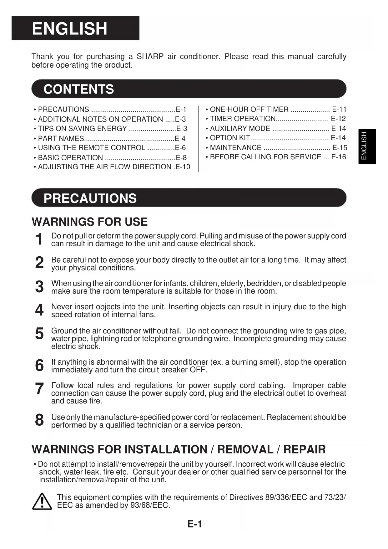
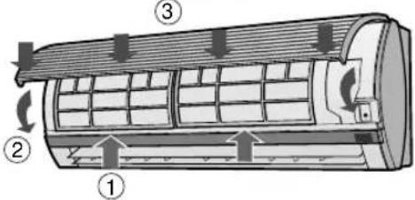
INDOOR UNIT
flowchart
graph TD
    A["Menu Icon"] --> B["Clock Icon"]
    B --> C["Fan Icon"]
    C --> D["Fan Icon"]
    D --> E["Roll Icon"]
    E --> F["Arrow to Panel"]
    style A fill:#f9f,stroke:#333
    style B fill:#ccf,stroke:#333
    style C fill:#cfc,stroke:#333
    style D fill:#fcc,stroke:#333
    style E fill:#ffc,stroke:#333
    style F fill:#cfc,stroke:#333
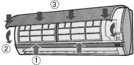
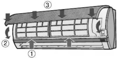
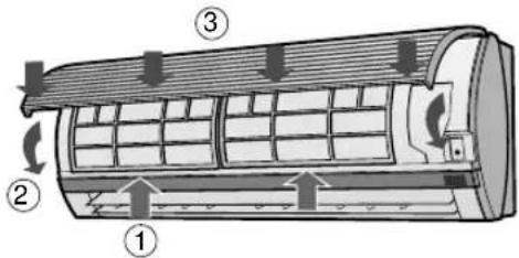
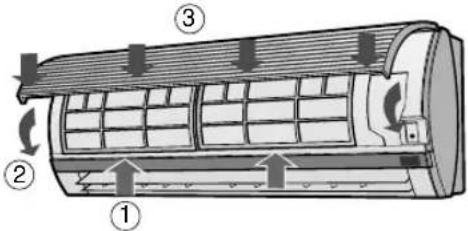
① Inlet (Air)
② Open Panel
③ Air Filters
④ AUX. Button
⑤ RECEIVER Window
⑥ Power Supply Cord
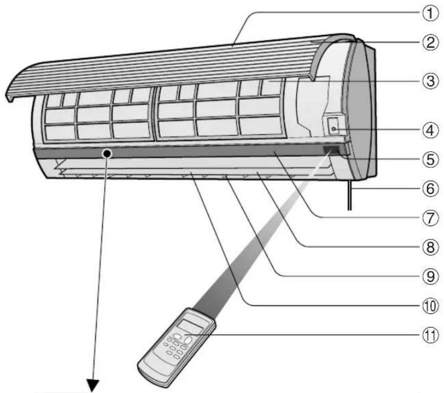
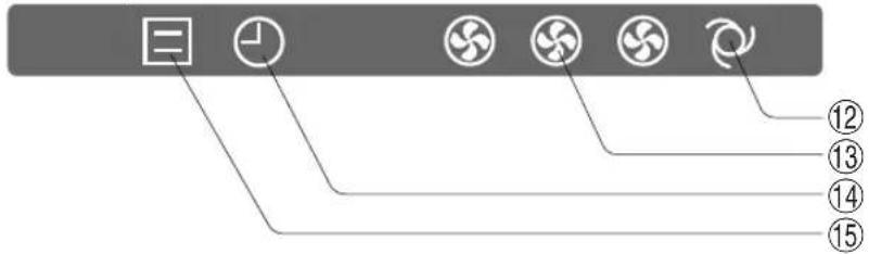
⑦ Indicator Panel
⑧ Vertical Adjustment Louvres
⑨ Horizontal Adjustment Louvres
⑩ Outlet (Air)
⑪ Remote Control
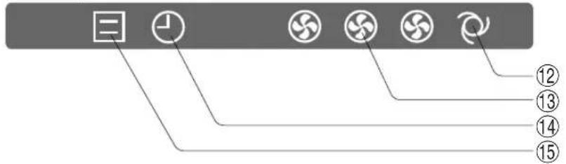
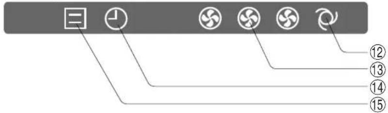
⑫ AUTO FAN SPEED Lamp (green 📋)
⑬ FAN SPEED Lamp (green
⑭ TIMER Lamp (orange ⏻)
⑮ OPERATION Lamp (red ☐)
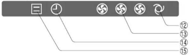
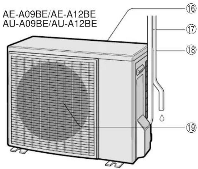
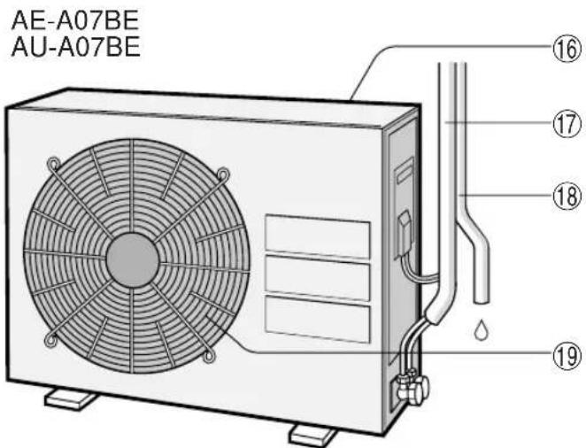
OUTDOOR UNIT
⑯ Inlet(Air)
⑰ Refrigerant Tube and Interconnecting Cord
⑱ Drainage Hose
⑲ Outlet(Air)
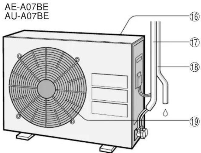
NOTE: Actual units might vary slightly from those shown above.
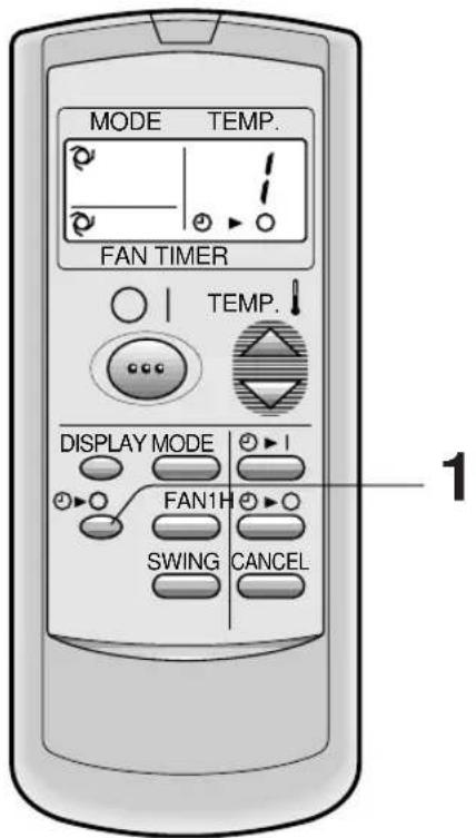
REMOTE CONTROL
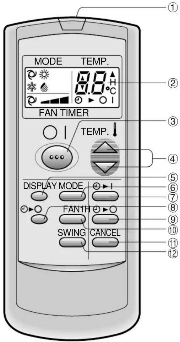
① TRANSMITTER
② DISPLAY (Liquid Crystal Display)
③ ON/OFF Button
④ THERMO. (Thermostat) Button
⑤ DISPLAY Button
⑥ MODE Button
⑦ TIMER ON Button (for setting the timer)
⑧ ONE-HOUR OFF TIMER Button
⑨ TIMER OFF Button (for setting the timer)
⑩ FAN Button
⑪ TIMER CANCEL Button
⑫ SWING Button
(The heat mode symbol 🌐 is provided only on models AY-A07BE/AY-A09BE/AY-A12BE)
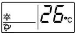
L.C.D. REMOTE CONTROL DISPLAY
⑬ MODE SYMBOLS

: AUTO : COOL


:HEAT:DRY
(only for AY-A07BE/
AY-A09BE/AY-A12BE)
⑭ FAN SPEED SYMBOLS

: AUTO : Manual

⑮ TEMPERATURE AND TIMER COUNT DOWN INDICATOR
⑯ TRANSMITTING SYMBOL
⑰ TIMER ON/TIMER OFF INDICATOR
Indicates when timer on or timer off is set.
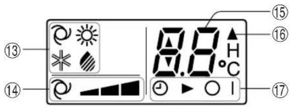
(The heat mode symbol 🌈 is provided only on models AY-A07BE/AY-A09BE/AY-A12BE)
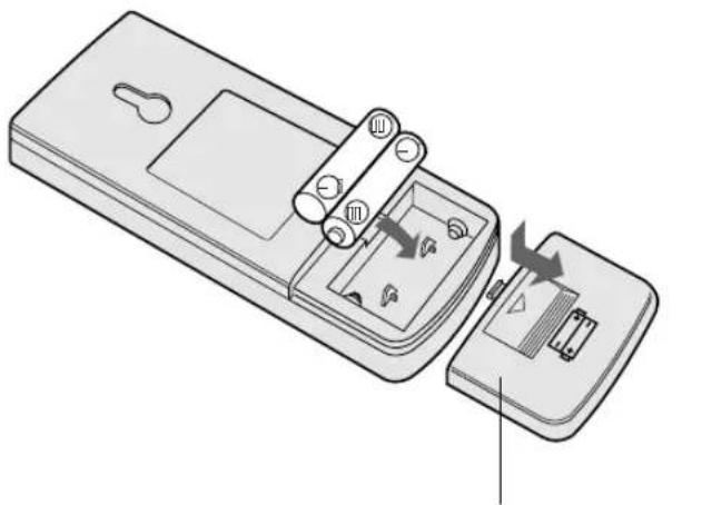
LOADING BATTERIES Use two size-AAA (R03) batteries.
1 Remove the battery cover at the back of the remote control.
2 Insert batteries in the compartment, making sure the ⊕ and ⊖ polarities are correctly aligned.
- Lines will be indicated on the display when batteries are properly installed.
3 Reinstall the battery cover.
natural_image
Diagram of a remote control device showing internal components and directional arrows (no text or symbols)Remote control cover
NOTES:
- The battery life is approximately one year in normal use.
- When you replace the batteries, always change both batteries, and make sure they are the same type.
- If the remote control does not operate properly after replacing the batteries, take out the batteries and reinstall them again after 30 seconds.
- If you will not be using the unit for a long time, remove the batteries from the remote control.
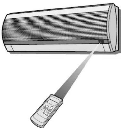
HOW TO USE THE REMOTE CONTROL
Point the remote control towards the unit's signal receiver window and press the desired button. The unit generates a beep when it receives the signal.
- Make sure there is no curtain or other object between the remote control and the unit.
- The remote control can send signals from up to 7 metres away.
natural_image
Illustration of a car air conditioner with a digital display and pointer, no text or symbols present
CAUTION
- Do not allow the signal receiver window to receive strong direct sunlight, since it can adversely affect its operation. If the signal receiver window is exposed to direct sunlight, close a curtain to block the light.
- Using a fluorescent lamp with a quick starter in the same room may interfere with transmission of the signal.
- The unit can be affected by signals transmitted from the remote control of a television, VCR or other equipment used in the same room.
- Do not leave the remote control in direct sunlight or near a heater. Also, protect the unit and remote control from moisture and shock which can discolour or damage them.
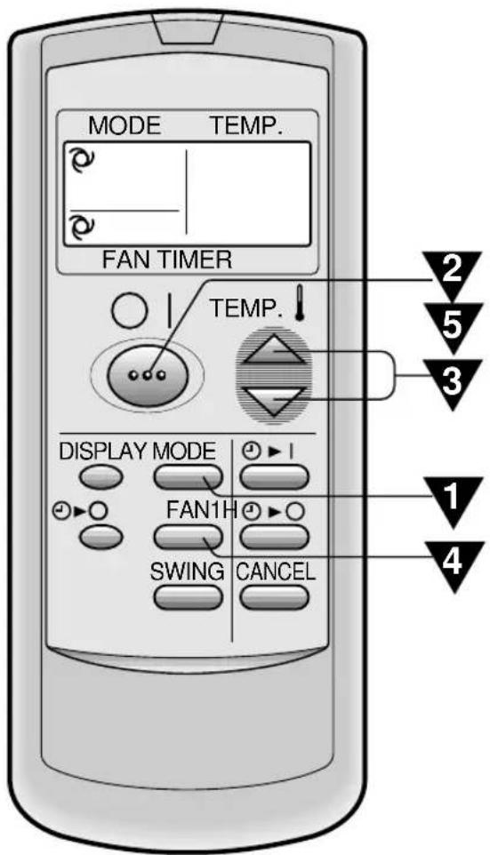
1
Press the MODE button to select the operation mode.
AUTO HEAT COOL DRY
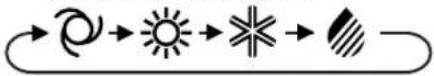
HEAT
(☀️ is only for AY-A07BE/AY-A09BE/AY-A12BE)
2
Press the ON/OFF button to start operation.
- The red OPERATION lamp ( ☐ on the unit will light.
3
Press the THERMO. button to set the desired temperature.
AUTO/DRY MODE
The temperature can be changed in 1°C increments within the range of 2°C higher to 2°C lower from the temperature automatically determined by the air conditioner.
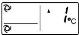
COOL(HEAT for AY-A07BE/AY-A09BE/AY-A12BE)MODE
The temperature can be set within the range of 18 to 32°C.
4
Please the FAN button to set the desired fan speed.
AUTO SOFT LOW HIGH
flowchart
graph LR
    A["Start"] --> B["Process Step"]
    B --> C["End"]
- In the DRY mode, the fan speed is pre-set to AUTO and cannot be changed.
5
To turn off the unit, press the ON/OFF button again.
- The red OPERATION lamp ( ☐ on the unit will turn off.
TIPS ABOUT AUTO MODE
In the AUTO mode, the temperature setting and mode are automatically selected according to the room temperature when the unit is turned on.
Modes and Temperature Settings for Models AH-A07BE/AH-A09BE/AH-A12BE
| Room temp. at operation start-up | Automatic Operation | |
| Mode Thermostat Setting | ||
| Below 24°C DRY Room Temp. at start-up | ||
| 24°C-26°C COOL | 24°C | |
| 26°C-28°C COOL | 25°C | |
| Above 28°C COOL | 26°C | |
Modes and Temperature Settings for Models AY-A07BE/AY-A09BE/AY-A12BE
| Room temp. at operation start-up | Automatic Operation | |
| Mode Thermostat Setting | ||
| Below 21°C HEAT | 23°C | |
| 21°C-24°C DRY Room Temp. at start-up | ||
| 24°C-26°C COOL | 24°C | |
| 26°C-28°C COOL | 25°C | |
| Above 28°C COOL | 26°C | |
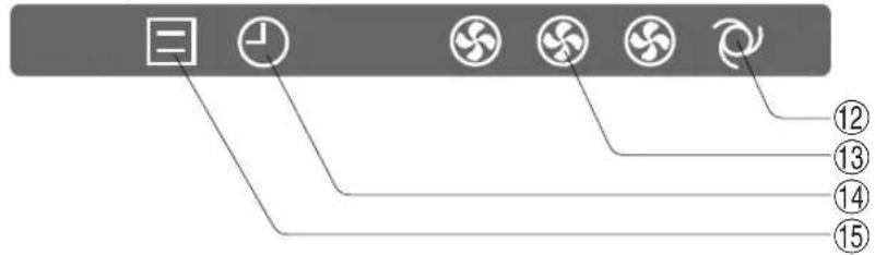
TIPS ABOUT FAN SPEED LAMP
During operation, the FAN SPEED Lamp will light up in 3 levels (2 levels for DRY mode) on the indicator panel of the unit to indicate the fan speed.
When fan speed is set to AUTO When fan speed is set to manual
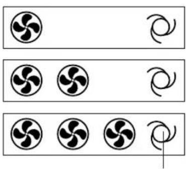
natural_image
Three rows of circular icons with curved lines, no text or symbols present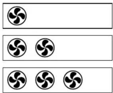
natural_image
Three identical rows of six black fan icons arranged horizontally (no text or symbols)Soft speed
Low speed
High speed
The AUTO FAN SPEED Lamp will light up.
To turn off the FAN SPEED Lamp, press the DISPLAY button.
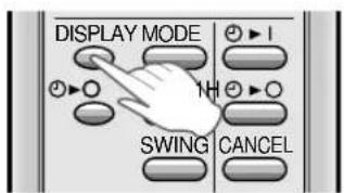
ADJUSTING THE AIR FLOW DIRECTION
VERTICAL AIR FLOW DIRECTION
The air flow direction is automatically preset in each mode as follows for optimum comfort:
| COOL and DRY mode Horizontal air flow | |
| HEAT mode (only for AY-A07BE/AY-A09BE/AY-A12BE) | Diagonal air flow |
HOW TO ADJUST THE AIR FLOW DIRECTION
Press the SWING button on the remote control once.
- The vertical adjustment louvre will change its angle continuously.
Press the SWING button again when the vertical adjustment louvre is at the desired position.
- The louvre will stop moving within the range shown in the diagram.
- The adjusted position will be memorized and will be automatically set to the same position when operated the next time.
Adjustment range
COOL and DRY mode
HEAT mode (only for AY-A07BE/AY-A09BE/AY-A12BE)
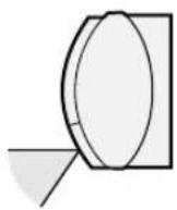
The adjustment range is narrower the SWING range in order to prevent condensation from dripping.
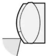
The range is wide so the air flow can be directed toward the floor.
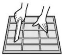
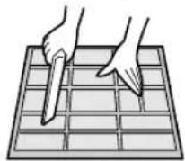
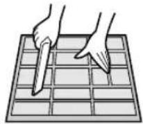
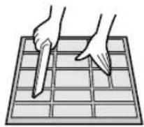
HORIZONTAL AIR FLOW DIRECTION
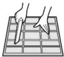
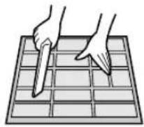
Hold the horizontal adjustment louvre as shown in the diagram and adjust the air flow direction.

natural_image
Illustration of a hand holding a rolled-up sheet of paper with horizontal lines and a shaded band (no text or symbols)
CAUTION
Never attempt to adjust the vertical adjustment louvres manually.
- Manual adjustment of the vertical adjustment louvre can cause the unit to malfunction when the remote control is used for the adjustment.
- When the vertical adjustment louvre is positioned at the lowest position in the COOL or DRY mode for an extended period of time, condensation may result.
When the ONE-HOUR OFF TIMER is set, the unit will stop operating after one hour.
1 Press the ONE-HOUR OFF TIMER button.
- The remote control displays “/②▶○
- The orange TIMER lamp (④) on the unit will light up.
- The unit will stop operating after one hour.
TO CANCEL
Press the CANCEL button.
- The orange TIMER lamp ( Ⓞ) on the unit will turn off.
Or, turn the unit off by pressing the ON/OFF button.
- The red OPERATION lamp (☐) and the orange TIMER lamp (☐) on the unit will turn off.
NOTES:
- The ONE-HOUR OFF TIMER operation has priority over TIMER ON and TIMER OFF operations.
- When the ONE-HOUR OFF TIMER is set while the unit is not operating, the unit will operate for an hour with the formerly set condition.
- If you wish to operate the unit for another hour before the ONE-HOUR OFF TIMER activates, press the ONE-HOUR OFF TIMER button again during operation.
TIMER OFF
The unit will turn off automatically according to your setting.
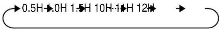
Timer duration can be set from minimum 0.5 hours (30 minutes) to maximum 12 hours.
Up to 9.5 hours, you can set by 0.5 hours (30 minutes) increments and from 10 to 12 hours, by 1 hour increment.
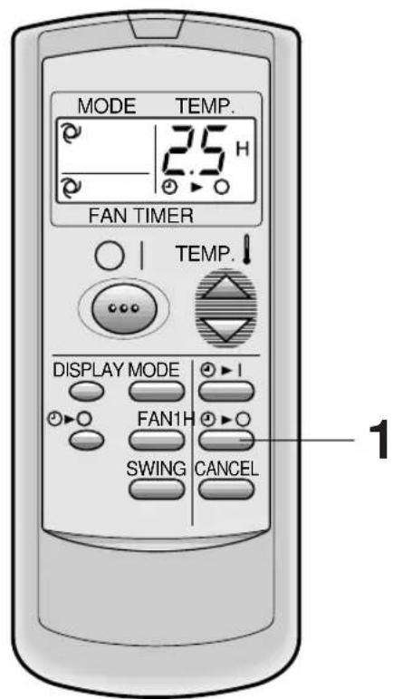
Example : When you wish to stop the operation 2.5 hours later.
Point the remote control at the signal receiver window on the unit.
1 Press the TIMER OFF ( ⏻ button and set time as desired.
- The time setting will change as you to press the button as follows,
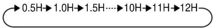
flowchart
graph LR
    A["0.5H"] --> B["1.0H"]
    B --> C["1.5H"]
    C --> D["..."]
    D --> E["10H"]
    E --> F["11H"]
    F --> G["12H"]
Hold the button pressed down for fast setting.
- The orange TIMER lamp ( ⏻ ) on the unit will light.
- The unit will generate a beep when it receives the signal.
- The time setting will count down to show remaining time.
When the TIMER OFF is set, the temperature setting is automatically adjusted to prevent the room from becoming excessively hot or too cold while you sleep. (Auto Sleep function)
COOL/DRY MODE:
- One hour after the timer operation begins, the temperature setting rises 1^ higher than the original thermostat setting.
HEAT MODE:
(only for models AY-A07BE/AY-A09BE/AY-A12BE)
- One hour after the timer operation begins, the temperature setting drops 3^ lower than the original thermostat setting.
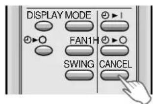
TO CANCEL TIMER
Press the CANCEL button.
• The orange TIMER lamp (💡) on the unit will turn off.
TO CHANGE TIMER SETTING
Press the TIMER button which you wish to change, (TIMER OFF or TIMER ON) and change the time setting.
TIMER ON
The unit will turn on automatically according to your setting.
Timer duration can be set from minimum 0.5 hours (30 minutes) to maximum 12 hours.
Up to 9.5 hours, you can set by 0.5 hours (30 minutes) increments and from 10 to 12 hours, by 1 hour increment.
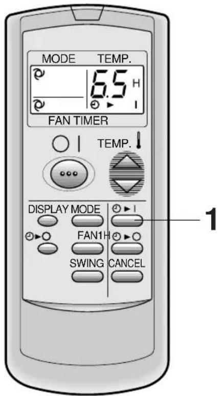
Example : When you wish the room temperature to be as desired 6.5 hours later.
Point the remote control at the signal receiver window on the unit.
1 Press the TIMER ON ( ⏻ button.
- The time setting will change as you press the button as follows.
Hold the button pressed down for fast setting.
- The orange TIMER lamp ( ⏻ on the unit will light.
- The unit will generate a beep when it receives the signal.
- The time setting will count down to show remaining time.
Select the mode, temperature and fan speed setting as desired.
- When the temperature is set with the TIMER ON, the temperature will show in the display for 5 seconds and then return to the time display.
- If you do not change the setting, the unit will operate with the latest setting.
- The unit will turn on prior to the set time to allow the room to reach the desired temperature by the programmed time. (Awaking function)
NOTES FOR TIMER SETTING AND OPERATION
- The latest time setting will be memorized and will appear on the remote control display the next time you set the TIMER OFF or TIMER ON.
- TIMER OFF and TIMER ON can not be set together.
The latest set TIMER will be active. - When ONE-HOUR OFF TIMER is set, TIMER OFF and TIMER ON will not be available.
- When ONE-HOUR OFF TIMER is set during TIMER OFF or TIMER ON duration, the TIMER ON or TIMER OFF will be cancelled.
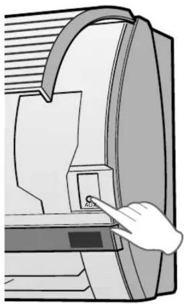
AUXILIARY MODE
Use this mode when the remote control is not available.
TO TURN ON
Lift the front panel of the indoor unit and press the AUX. button on the operation panel.
- The red OPERATION lamp (☐) on the unit will light and the unit will start operating in the AUTO mode.
- The fan speed and temperature setting are set to AUTO.
TO TURN OFF
Press the AUX. button on the operation panel again.
- The red OPERATION lamp (☐) on the unit will turn off.
NOTE:
If the AUX. button is pressed during normal operation, the unit will turn off.
natural_image
Illustration of a hand pressing a button labeled 'ACX' on a computer monitor (no text or symbols beyond the label)OPTION KIT
Air Purifying Filter
During operation of the air conditioner, the air purifying filter removes dust and tobacco smoke from the air and discharges clean air.
The apatite antibacterial material used in the air purifying filter suppresses activities of adsorbed viruses and other germs.
The replacement period for the disposable type is approximately 3\~6 months.
Contact your dealer for the purchase of this option.

natural_image
3D illustration of a layered rectangular block with textured surface (no text or symbols)Type AZ-F900B
CAUTION
Be sure to disconnect the power cord from the wall outlet or turn off the circuit breaker before performing any maintenance.
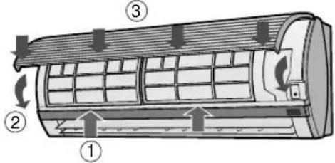
CLEANING THE FILTERS
The air filters should be cleaned every two weeks.
1 TURN OFF THE UNIT
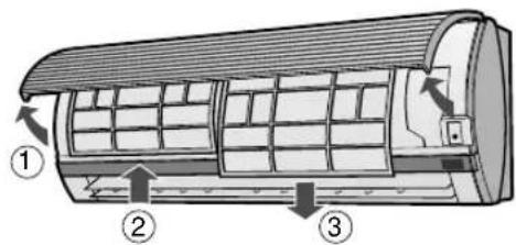
2 REMOVE THE FILTERS
1 Lift the open panel.
2 Push the air filters up slightly to unlock them.
3 Pull the air filters down to remove them.
3 CLEAN THE FILTERS
Use a vacuum cleaner to remove dust. If the filters are dirty, wash them with warm water and a mild detergent. Dry filters in the shade before reinstalling.
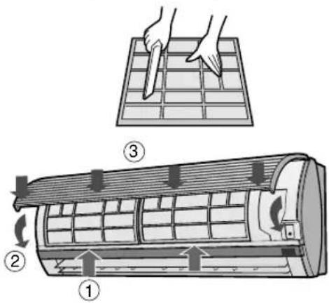
4 REINSTALL THE FILTERS
1 Reinstall the filters in the original positions.
2 Close the front panel.
3 Push the center part of the panel firmly to lock it in place.
CLEANING THE UNIT AND THE REMOTE CONTROL
CAUTION
- Wipe them with a soft cloth.
- Do not directly splash or pour water on them. We can cause electrical shock or equipment damage.
- Do not use hot water, thinner, abrasive powders or strong solvents.
MAINTENANCE AFTER AIR CONDITIONER SEASON
1 Operate the unit in the COOL mode, temperature setting 32^ C, for about half a day to allow the mechanism to thoroughly dry.
2 Stop the operation and unplug the unit. Turn off the circuit breaker, if you have one exclusively for the air conditioner.
3 Clean the filters, then reinstall them.
MAINTENANCE BEFORE AIR CONDITIONER SEASON
1 Make sure that the air filters are not dirty.
2 Make sure that nothing obstructs the air inlet or outlet.
CAUTION
3 Check the outdoor mounting rack periodically for wear and to make sure it is firmly in place.
BEFORE CALLING FOR SERVICE
The following conditions do not denote equipment malfunctions
| UNIT DOES NOT OPERATEThe unit will not operate if it is turned on immediately after it is turned off. The unit will not operate immediately after the mode is changed.This is to protect the internal mechanisms. Wait 3 minutes before operating the unit. | SWISHING NOISEThe soft, swishing noise is the sound of the refrigerant flowing inside the unit. |
| WATER VAPOURIn the COOL and DRY operation, water vapour can sometimes be seen at the air outlet due to the difference between the room air temperature and the air discharged by the unit.In the HEAT operation, water vapour may flow out of the outdoor unit during de-icing. (Only in models AY-A07BE/AY-A09BE/AY-A12BE) | |
| UNIT DOES NOT SEND OUT WARM AIR(Models AY-A07BE/AY-A09BE/AY-A12BE)The unit is preheating or de-icing. | |
| ODORSCarpet and furniture odors that entered into the unit and the air conditioner's inner component odors at the early stage of installation may be sent out from the unit. | |
| CRACKING NOISEThe unit may produce a cracking noise. This sound is generated by the friction of the front panel and other components expanding or connecting due to a temperature change. |
If the unit appears to be malfunctioning, check the following points before calling for service.
| IF THE UNIT FAILS TO OPERATE |
| Check to see if the circuit breaker has tripped or the fuse has blown. |
| IF THE UNIT FAILS TO COOL (OR HEAT) THE ROOM EFFECTIVELY | ||
| Check the filters. If dirty, clean them. | Check the outdoor unit to make sure nothing is blocking the air inlet or outlet. | Check the thermostat is proper setting. |
| Make sure windows and doors are closed tightly. | A large number of people in the room can prevent the unit from achieving the desired temperature. | Check whether any heat-generating appliances are operating in the room. |
| IF THE UNIT FAILS TO RECEIVE THE REMOTE CONTROL SIGNAL | ||
| Check whether the remote control batteries have become old and weak. | Try to send the signal again with the remote control pointed properly towards the unit's signal receiver window. | Check whether the remote control batteries are installed with the polarities properly aligned. |
Please call for service when OPERATION Lamp and TIMER Lamp on the indicator panel blink.
flowchart
graph TD
    A["Menu Icon"] --> B["Clock Icon"]
    B --> C["Fan Icon"]
    C --> D["Fan Icon"]
    D --> E["Roll Icon"]
    E --> F["Arrow to Screen Icon"]
    style A fill:#f9f,stroke:#333
    style B fill:#ccf,stroke:#333
    style C fill:#cfc,stroke:#333
    style D fill:#fcc,stroke:#333
    style E fill:#cff,stroke:#333
    style F fill:#ffc,stroke:#333
natural_image
Illustration of a car air conditioner with a handheld flash unit emitting light (no text or symbols)
VORSICHT
1
natural_image
Illustration of a hand pressing down on a curved panel with horizontal lines (no text or symbols)
VORSICHT
natural_image
Illustration of a hand pressing a button labeled 'ACX' on a computer monitor (no text or symbols beyond the label)WAHLAUSSTATTUNG
natural_image
3D illustration of a layered rectangular block with textured surface (no text or symbols)Typ AZ-F900B
VORSICHT
1 SCHALTEN SIE DAS GERÄT AUS
2 ENTNEHMEN SIE DIE FILTER
D.B. = Sec W.B. = Humide

flowchart
graph TD
    A["Menu Icon"] --> B["Clock Icon"]
    B --> C["Fan Fan Icon"]
    C --> D["Fan Circle Icon"]
    D --> E["Swing Arrow Icon"]
    style A fill:#f9f,stroke:#333
    style B fill:#ccf,stroke:#333
    style C fill:#cfc,stroke:#333
    style D fill:#fcc,stroke:#333
    style E fill:#ffc,stroke:#333
natural_image
Diagram of a remote control device showing internal components and directional arrows (no text or symbols)natural_image
Illustration of a handheld air conditioner with a digital display and pointer, no text or symbols present
ATTENTION
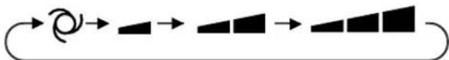
flowchart
graph LR
    A["Start"] --> B["Circle"]
    B --> C["Right Arrow"]
    C --> D["Right Triangle"]
    D --> E["Right Square"]
    E --> F["Right Rectangle"]
natural_image
Three identical abstract diagrams of fan-like symbols with no text or labelsnatural_image
Three identical circular diagrams with black fan-like symbols inside, arranged horizontally (no text or labels)Faible
Vitesse basse
Vitesse haute
natural_image
Illustration of a hand pressing down on a curved panel with horizontal lines and a shaded band (no text or symbols)
ATTENTION
POUR MODIFIER LE REGLAGE D'HEURE
natural_image
Illustration of a hand pressing a button on a computer monitor (no text or symbols visible)KIT EN OPTION
natural_image
3D illustration of a layered rectangular block with textured surface (no text or symbols)Type AZ-F900B
ATTENTION
flowchart
graph TD
    A["Button"] --> B["Clock Icon"]
    B --> C["Circle with Turn"]
    C --> D["Circle with Turn"]
    D --> E["Circle with Turn"]
    E --> F["Arrow with Arrow"]
    style A fill:#f9f,stroke:#333
    style B fill:#ccf,stroke:#333
    style C fill:#cfc,stroke:#333
    style D fill:#fcc,stroke:#333
    style E fill:#cff,stroke:#333
    style F fill:#ffc,stroke:#333
natural_image
Technical line drawing of a remote control device with internal components and directional arrows indicating movement (no text or symbols)natural_image
Illustration of a car air conditioner with a handheld digital display emitting a beam of light (no text or symbols)
PRECAUCIÓN

CORRIENTE DE AIRE VERTICAL
natural_image
Illustration of a hand pressing down on a curved panel with horizontal stripes (no text or symbols)
PRECAUCIÓN
natural_image
Illustration of a hand pressing a button labeled 'AUX' on a computer screen (no text or symbols beyond the label)KIT OPCIONAL
natural_image
3D illustration of a layered rectangular block with textured top surface (no text or symbols)Tipo AZ-F900B
PRECAUCION
1 DESCONECTE LA UNIDAD
2 SAQUE LOS FILTROS
flowchart
graph TD
    A["Button"] --> B["Clock Icon"]
    B --> C["Waveform Icon"]
    C --> D["Waveform Icon"]
    D --> E["Waveform Icon"]
    E --> F["Label 12"]
    E --> G["Label 13"]
    E --> H["Label 14"]
    E --> I["Label 15"]
⑭ SIMBOLI DELLA VELOCITA' DEL VENTILATORE

: AUTOMATICO
natural_image
Illustration of a car air conditioner with a handheld digital display emitting a beam of light (no text or symbols)
PRECAUZIONI

natural_image
Illustration of a hand pressing down on a curved panel with horizontal lines and a shaded band (no text or symbols)
PRECAUZIONE
PER CAMBIARE L'IMPOSTAZIONE DEL TIMER
natural_image
Illustration of a hand pressing a button labeled 'AUX' on a computer screen (no text or symbols beyond the label)KIT OPZIONALE
natural_image
Stack of three rectangular panels with textured surfaces, no text or symbols visibleTipo AZ-F900B
PRECAUZIONI
1 SPEGNETE L'UNITA'
2 RIMUOVETE I FILTRI
INDICAÇÕES REFERENTES AOS MODELOS AY-A07BE/AY-A09BE/AY-A12BE
flowchart
graph TD
    A["Input"] --> B["Clock"]
    B --> C["Output Module 1"]
    C --> D["Output Module 2"]
    D --> E["Output Module 3"]
    E --> F["Output Module 4"]
    F --> G["Output Module 5"]
    G --> H["Output Module 6"]
    H --> I["Output Module 7"]
    I --> J["Output Module 8"]
    J --> K["Output Module 9"]
    K --> L["Output Module 10"]
    L --> M["Output Module 11"]
    M --> N["Output Module 12"]
natural_image
Diagram of a remote control device showing internal components and directional arrows (no text or symbols)Tampa do controlo remoto
NOTAS:
natural_image
Illustration of a wall-mounted air conditioner with a digital display emitting a beam of light (no text or symbols)
ATENÇÃO

natural_image
Four circular fan icons in a row, one with a spiral line on the right (no text or symbols)natural_image
Illustration of a hand holding a curved panel with horizontal lines and a ruler, no text or symbols present
ATENÇÃO
PARA MODIFICAR A HORA
natural_image
3D illustration of a two-layered rectangular block (no text or symbols)Tipo AZ-F900B
ATENÇÃO
1 DESLIGAR A UNIDADE
2 RETIRAR OS FILTROS
1 Levante o painel.
natural_image
Diagram of a remote control device showing internal components and directional arrows (no text or symbols)natural_image
Illustration of a mobile phone emitting a laser beam from a rectangular air conditioner (no text or symbols)
ΠΡΟΣΟΧΗ
natural_image
Illustration of a hand pressing down on a curved surface with horizontal lines and a shaded band (no text or symbols)
ΠΡΟΣΟΧΗ
natural_image
3D illustration of a layered rectangular block with textured top surface (no text or symbols)Túποσ AZ-F900B
ΠΡΟΣΟΧΗ
WAARSCHUWINGEN BIJ DE PLAATSING / INSTALLATIE
① Inlaat (lucht)
② Opklapbaar paneel
③ Luchtfilters
④ HELP-toets (AUX.)
⑤ ONTVANGST-venster
⑥ Netsnoer
⑦ Indicatorpaneel
⑧ Verticaal instelbare jaloezieën
⑨ Horizontaal instelbare jaloezieën
⑩ Uitlaat (lucht)
⑪ Afstandsbediening
⑫ AUTOMATISCHE VENTILATORSNELHEID-lamp (groen Ⓤ)
⑬ VENTILATORSNELHEID-lamp (groen
⑭ SCHAKELKLOK-indicator (oranje ⏻)
⑮ BEDRIJF-indicator (rood)
BUITEN-UNIT
⑯ Inlaat (lucht)
⑰ Koelstofbuis en tussenkabel
⑱ Afvoerslang
⑲ Uitlaat (lucht)
natural_image
Illustration of a handheld air conditioner with a digital display and pointer, no text or symbols present
LET OP
natural_image
Three rows of circular icons with different leaf patterns, no text or symbols presentnatural_image
Three identical panels of a fan icon, each containing six black fan-like symbols, arranged horizontally (no text or labels)Zachte snelheid
Lage snelheid
Hoge snelheid
De AUTO VENTILATORSNELHEID-lamp begint te branden.
INSTELLEN VAN DE LUCHTSTROOMRICHTING
VERTICALE LUCHTSTROOMRICHTING
natural_image
Illustration of a hand holding a curved object with horizontal stripes, no text or symbols present
LET OP
KOELEN/DROGEN-FUNCTIE:
natural_image
Stacked rectangular panels with textured surfaces, no visible text or symbolsType AZ-F900B
LET OP
1 SCHAKEL HET TOESTEL UIT
2 VERWIJDER DE FILTERS
natural_image
Illustration of a handheld air conditioner with a digital display and pointer, no text or symbols present
UYARI

HAVA AKİŞ YÖNÜNÜN AYARLANMASI
DÜŞEY HAVA AKIŞI
natural_image
Illustration of a hand pressing down on a curved panel with horizontal lines (no text or symbols)
UYARI
BİR SAAT SONRA KAPANMA AYARI
natural_image
Illustration of a hand pressing a button labeled 'AUX' on a computer monitor (no text or symbols beyond the label)OPSİYON KİTİ
natural_image
3D illustration of a layered rectangular block with textured surface (no text or symbols)Tip AZ-F900B
UYARI
1 ÜNİTEYİ KAPATIN
2 FILTRELERİ ÇIKARIN
4 FILTRELERİ YERİNE TAKIN