
AEX08BEC - Air-conditioner SHARP - Free user manual and instructions
Find the device manual for free AEX08BEC SHARP in PDF.

| Product Type | Air Conditioner |
| Brand | Sharp |
| Model | AEX08BEC |
| Operating Modes | Auto, Cool, Heat, Dry, Fan Only |
| Plasmacluster Technology | Ionization to purify air and cool |
| Self-Cleaning | SELF CLEAN function to dry interior |
| Timer | On, Off, Off after one hour |
| Full Power Function | Rapid cooling or heating |
| Airflow Direction | Vertical (motorized) and horizontal (manual) |
| Display | Indoor/outdoor temperature, power monitor |
| Remote Control | With AAA batteries, range 7 meters |
| Power Supply | 220-240 V, 50 Hz |
| Max Power Consumption | 12 A (setting H), 8 A (setting L) – depending on model |
| Filter Maintenance | Air filters: every 2 weeks; deodorizing filter: every 3-6 months |
| Spare Parts | Deodorizing filter AZ-F910C, dust filter AZ-F900C |
| Safety | Mandatory grounding, leakage breaker, do not insert objects |
| Operating Temperature Range | Cool: 21-32°C indoor, 21-43°C outdoor; Heat: 20-27°C indoor, -8.5-24°C outdoor |
Frequently Asked Questions - AEX08BEC SHARP
User questions about AEX08BEC SHARP
0 question about this device. Answer the ones you know or ask your own.
Ask a new question about this device
Download the instructions for your Air-conditioner in PDF format for free! Find your manual AEX08BEC - SHARP and take your electronic device back in hand. On this page are published all the documents necessary for the use of your device. AEX08BEC by SHARP.
USER MANUAL AEX08BEC SHARP
natural_image
Illustration of a car air conditioner with a digital display and a sensor emitting a beam of light (no text or symbols)INDOOR UNIT
ZIMMERGERÄT
UNITE INTERIEURE
UNIDAD INTERIOR
UNITA' INTERNA
UNIDADE INTERIOR
ΕΣΩΤΕΡΙΚΗ ΣΥΣΚΕΥΗ
BINNEN-UNIT
iÇ ÜNİTE
ВНУТРЕННИЙ БЛОК
AY-XP08CE
AY-XP10CE
AY-XP13CE
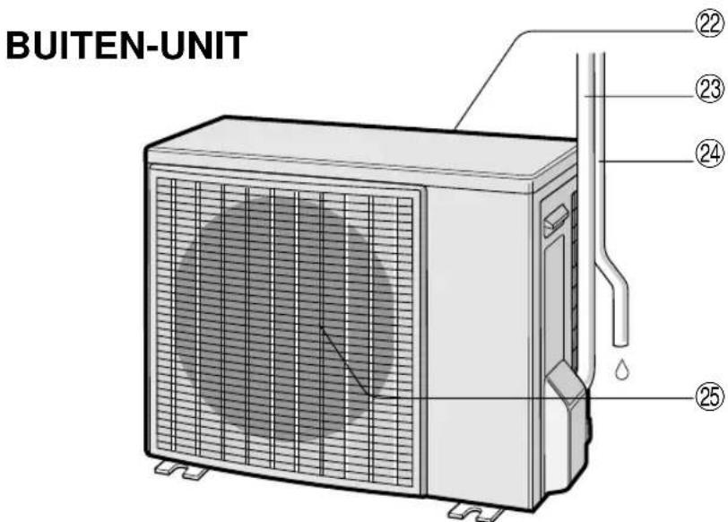
OUTDOOR UNIT
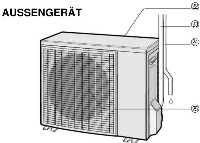
AUSSENGERÄT
UNITE EXTERIEURE
UNIDAD EXTERIOR
UNITA' ESTERNA
UNIDADE EXTERIOR
ΕΞΩΤΕΡΙΚΗ ΣΥΣΚΕΥΗ
BUITEN-UNIT
DIŞ ÜNİTE
НАРУЖНИЙ БЛОК
AE-X08BE-c
AE-X10BE-c
AE-X13BE
AY-XP08CE AY-XP10CE AY-XP13CE
SPLIT TYPE
ROOM AIR CONDITIONER
ZWEITEILIGES
KLIMAGERAT
CLIMATISEUR INDIVIDUEL
EN DEUX PARTIES
MANUAL DE INSTRUÇÕES
Thank you for purchasing a SHARP air conditioner. Please read this manual carefully before operating the product.
CONTENTS
- PRECAUTIONS ......E-1
- PART NAMES......E-3
- SETTING DUST COLLECTING FILTER AND DEODORANT FILTER ....E-5
• USING THE REMOTE CONTROL .....E-6
• BASIC OPERATION .....E-8
• ADJUSTING THE AIR FLOW DIRECTION ...E-10
• FULL POWER OPERATION .....E-11 - ONE-HOUR OFF TIMER ......E-11
• TIPS ABOUT PLASMACLUSTER OPERATION... E-12
• PLASMACLUSTER OPERATION ..... E-13
- SELF CLEAN OPERATION ...... E-13
• TIMER OPERATION...... E-14
• AUXILIARY MODE ...... E-16
• POWER SELECTOR ...... E-16
• ADDITIONAL NOTES ON OPERATION ... E-17
• TIPS ON SAVING ENERGY ...... E-17
- MAINTENANCE ...... E-18
- BEFORE CALLING FOR SERVICE .. E-20
PRECAUTIONS
WARNINGS FOR USE
1 Do not pull or deform the power supply cord. Pulling and misuse of the power supply cord can result in damage to the unit and cause electrical shock.
2 Be careful not to expose your body directly to the outlet air for a long time. It may affect your physical conditions.
3 When using the air conditioner for infants, children, elderly, bedridden, or disabled people make sure the room temperature is suitable for those in the room.
4 Never insert objects into the unit. Inserting objects can result in injury due to the high speed rotation of internal fans.
5 Ground the air conditioner without fail. Do not connect the grounding wire to gas pipe, water pipe, lightning rod or telephone grounding wire. Incomplete grounding may cause electric shock.
6 If anything is abnormal with the air conditioner (ex. a burning smell), stop the operation immediately and turn the circuit breaker OFF.
7 Follow local rules and regulations for power supply cord cabling. Improper cable connection can cause the power supply cord, plug and the electrical outlet to overheat and cause fire.
8 Use only the manufacture-specified power cord for replacement. Replacement should be performed by a qualified technician or a service person.
WARNINGS FOR INSTALLATION / REMOVAL / REPAIR
- Do not attempt to install/remove/repair the unit by yourself. Incorrect work will cause electric shock, water leak, fire etc. Consult your dealer or other qualified service personnel for the installation/removal/repair of the unit.

This equipment complies with the requirements of Directives 89/336/EEC and 73/23/EEC as amended by 93/68/EEC.
PRECAUTIONS
CAUTIONS FOR USE
1 Open a window or door periodically to ventilate the room, especially when using gas appliances. Insufficient ventilation may cause oxygen shortage.
2 Do not operate the buttons with wet hand. It may cause electric shock.
3 For safety, turn the circuit breaker off when not using the unit for an extended period of time.
4 Check the outdoor unit mounting rack periodically for wear and to make sure it is firmly in place.
5 Do not put anything on the outdoor unit nor step on it. The object or the person may fall down or drop, causing injury.
6 This unit is designed for residential use. Do not use for other applications such as in a kennel or greenhouse to raise animals or grow plants.
7 Do not place a vessel with water on the unit. If water penetrates into the unit, electrical insulations may deteriorate and cause electric shock.
8 Do not block the air inlets nor outlets of the unit. It may cause insufficient performance or troubles.
9 Be sure to stop the operation and turn the circuit breaker off before performing any maintenance or cleaning. A fan is rotating inside the unit and you may get injured.
10 Do not splash or pour water directly on the unit. Water can cause electrical shock or equipment damage.
11 This appliance is not intended for use by young children or infirm persons without supervision.
Young children should be supervised to ensure that they do not play with the appliance.
CAUTIONS FOR LOCATION / INSTALLATION
- Make sure to connect the air conditioner to power supply of the rated voltage and frequency.
Use of a power supply with improper voltage and frequency can result in equipment damage and possible fire. - Do not install the unit in a place where inflammable gas may leak. It may cause fire. Install the unit in a place with minimal dust, fumes and moisture in the air.
- Arrange the drain hose to ensure smooth drainage. Insufficient drainage may cause wetting of the room, furniture etc.
- Make sure a leak breaker or a circuit breaker is installed, depending on the installation location, to avoid electrical shock.
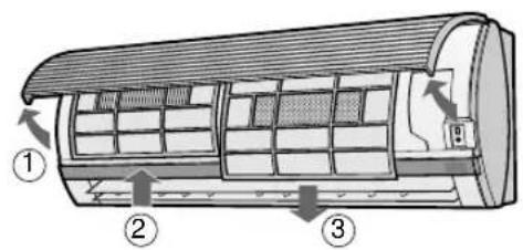
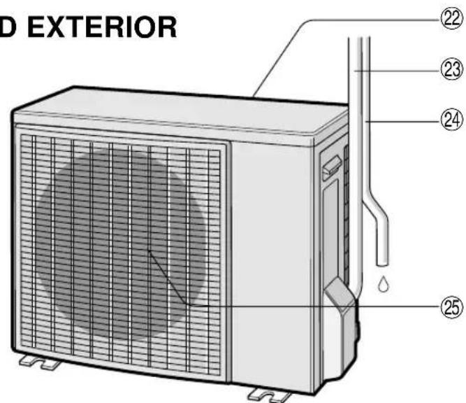
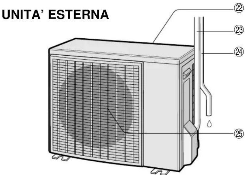
INDOOR UNIT


① DUST COLLECTION FILTER (non-washable)
②DEODORANT FILTER (washable)
③Inlet (Air)
④Open Panel
⑤ Air Filters
⑥POWER SELECTOR SWITCH
(only for AY-XP13CE)
⑦ AUX. Button
⑧RECEIVER Window
⑨Power Supply Cord
⑩Indicator Panel
⑪ Vertical Adjustment Louvres
⑫Horizontal Adjustment Louvres
⑬ Outlet (Air)
⑭ Remote Control
⑮ OUTDOOR Temp. Lamp (green ⬇!)
⑯ TEMPERATURE INDICATOR
⑰ROOM Temp. Lamp (green
⑱ POWER MONITOR
⑲PLASMACLUSTER Lamp (blue, green)
⑳TIMER Lamp (orange 📋)
②OPERATION Lamp (red ☐)
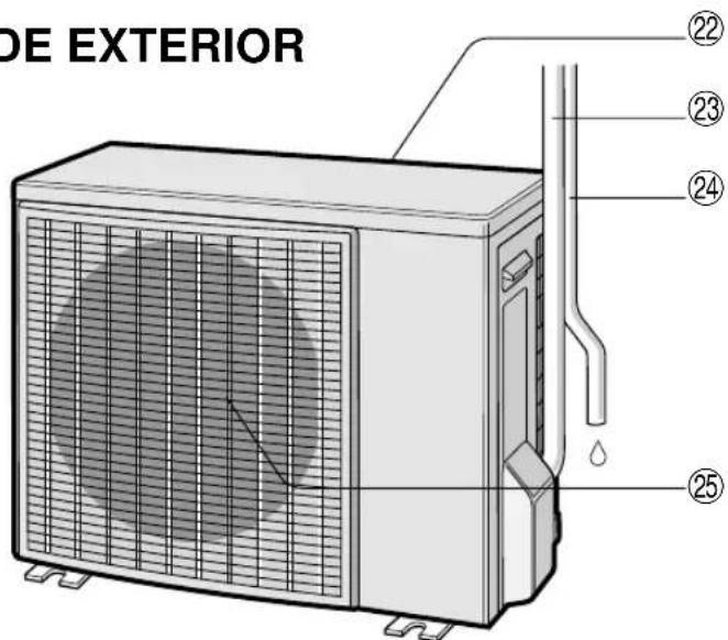
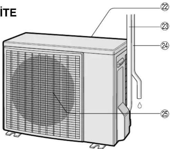
②Inlet (Air)
②3 Refrigerant Tube and Interconnecting Cord
⑳Drainage Hose
⑳Outlet (Air)
NOTE: Actual units might vary slightly from those shown above.
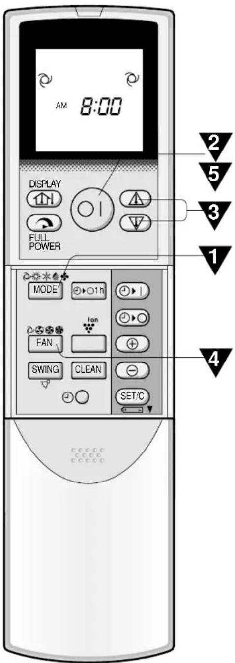
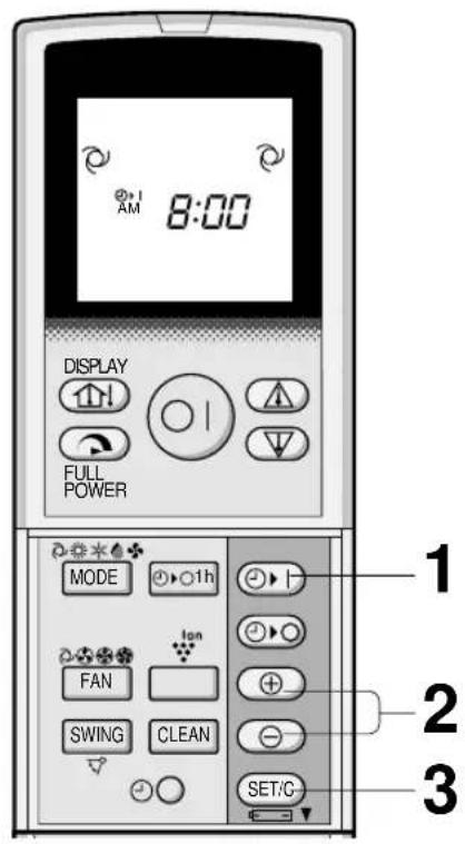
REMOTE CONTROL
①TRANSMITTER
②DISPLAY (Liquid Crystal Display)
③DISPLAY Button
④FULL POWER Button
⑤ON/OFF Button
⑥THERMO. (Thermostat) Button
⑦MODE Button
⑧FAN Button
⑨ONE-HOUR OFF TIMER Button
⑩ TIMER ON Button (for setting the timer)
⑪ TIMER OFF Button (for setting the timer)
⑫PLASMACLUSTER Button
⑬TIME ADVANCE Button
⑭TIME REVERSE Button
⑮ SELF CLEAN Button
⑯ TIMER SET/CANCEL Button
⑰ Indicates BATTERY COMPARTMENT is below this mark
⑱ CLOCK Button
⑲ SWING Button
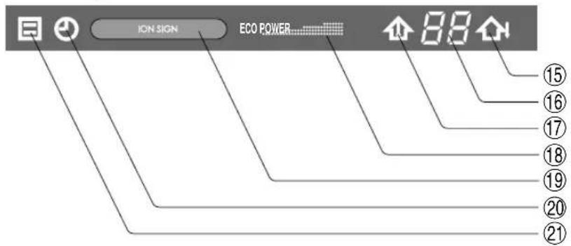
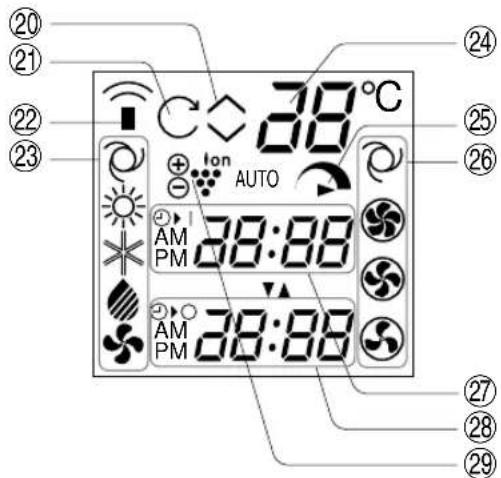
L.C.D. REMOTE CONTROL DISPLAY
⑳ THERMOSTAT SETTING FOR AUTO AND DRY MODES
②1 SELF CLEAN SYMBOL
⑳TRANSMITTING SYMBOL
②3 MODE SYMBOLS
⑳TIMER ON INDICATOR/CLOCK
Indicates the on timer preset time or current time.
⑳TIMER OFF INDICATOR
Indicates the preset time for off timer or one-hour off timer.
⑲PLASMACLUSTER SYMBOL
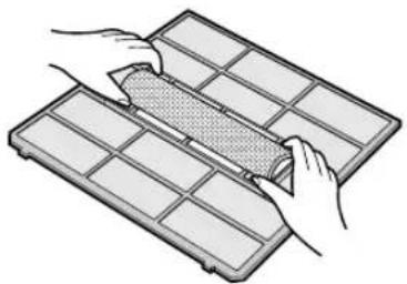
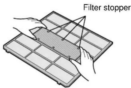
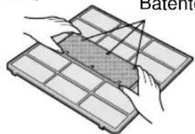
SETTING DUST COLLECTION FILTER AND DEODORANT FILTER
The dust collection filter and the deodorant filter are packed as accessory of this unit. During operation of the air conditioner, the filters remove dust and tobacco smoke from the air and discharges clean air.
DUST COLLECTION FILTER (gray)
Set the black side facing upward.
DEODORANT FILTER (green)
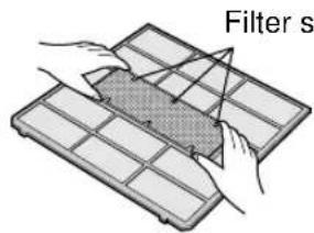

1 Take out the air filters.
① Open the open panel.
②Push the air filters up slightly to unlock them.
③Pull the air filters down to remove them.
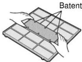
2 Set the dust collection filter and the deodorant filter under the filter stoppers located on the air filter.
3 Reinstall the air filters
①Reinstall the air filters in the original positions.
②Close the open panel.
③Push the arrow-marked of the panel firmly to lock it in place.
Precautions
- The filters are sealed in a plastic bag to keep their dust collection effect.
Do not open the bag until using the filters. (Otherwise the filters life may get shorter.) - Do not expose the filters to direct sunlight. (Otherwise they may deteriorate.)
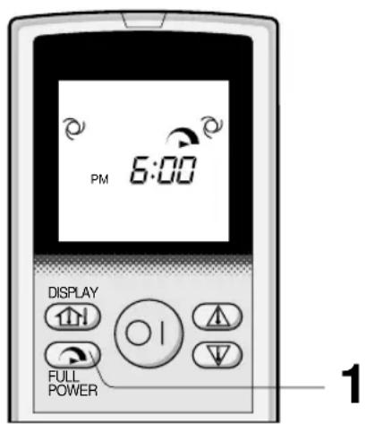
LOADING BATTERIES Use two size-AAA (R03) batteries.
1 Remove the remote control cover.
2 Insert batteries in the compartment, making sure the ⊕ and ⊖ polarities are correctly aligned.
- The display indicates "AM 6:00" when batteries are properly installed.
3 Reinstall the cover.
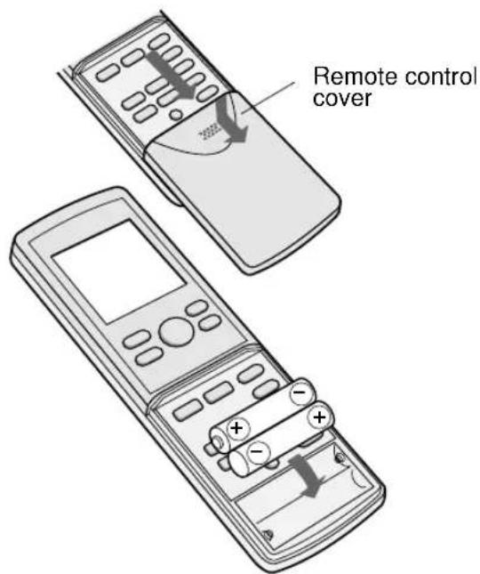
NOTES:
• The battery life is approximately one year in normal use.
- When you replace the batteries, always change both batteries, and make sure they are the same type.
- If the remote control does not operate properly after replacing the batteries, take out the batteries and reinstall them again after 30 seconds.
- If you will not be using the unit for a long time, remove the batteries from the remote control.
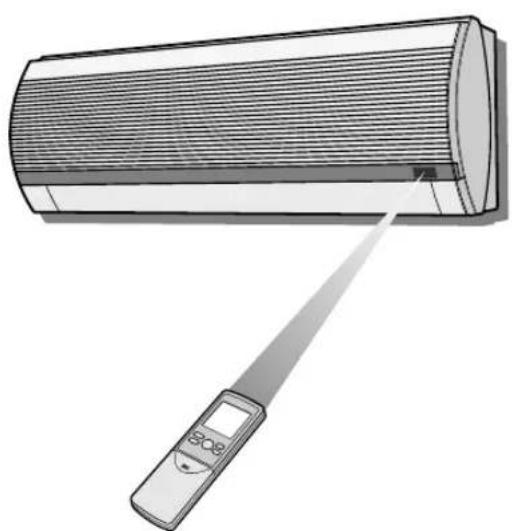
HOW TO USE THE REMOTE CONTROL
Point the remote control towards the unit's signal receiver window and press the desired button. The unit generates a beep when it receives the signal.
- Make sure there is no curtain or other object between the remote control and the unit.
- The remote control can send signals from up to 7 metres away.
natural_image
Illustration of a wall-mounted air conditioner with a digital display and pointer, no text or symbols present
CAUTION
- Do not allow the signal receiver window to receive strong direct sunlight, since it can adversely affect its operation. If the signal receiver window is exposed to direct sunlight, close a curtain to block the light.
- Using a fluorescent lamp with a quick starter in the same room may interfere with transmission of the signal.
- The unit can be affected by signals transmitted from the remote control of a television, VCR or other equipment used in the same room.
- Do not leave the remote control in direct sunlight or near a heater. Also, protect the unit and remote control from moisture and shock which can discolour or damage them.
SET CURRENT CLOCK TIME
There are two clock modes: 12-hour mode and 24-hour mode.
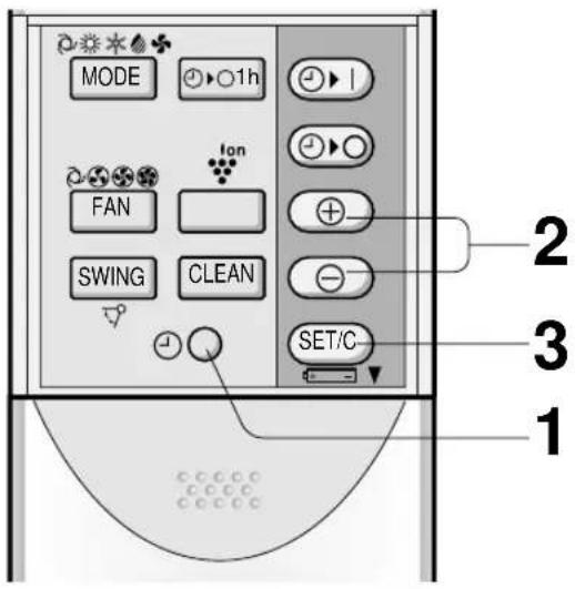
Example: 5 o'clock in the afternoon
| Clock Display | |
| 12-hour mode PM 5:00 | |
| 24-hour mode 17:00 | |
1 To set to the 12-hour mode, press the CLOCK button once in the first step. To set to the 24-hour mode, press the CLOCK button twice in the first step.
2 Press the TIME ADVANCE or REVERSE button to set the current time.
- Keep the button pressed to advance or reverse the time display quickly.
3 Press the SET/C button.
- The colon (:) blinks to indicate that the clock is functioning.
NOTE:
- The current time cannot be set when the timer is operating.

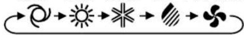
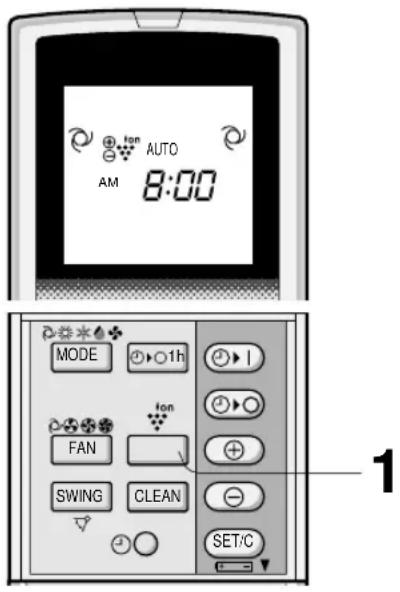
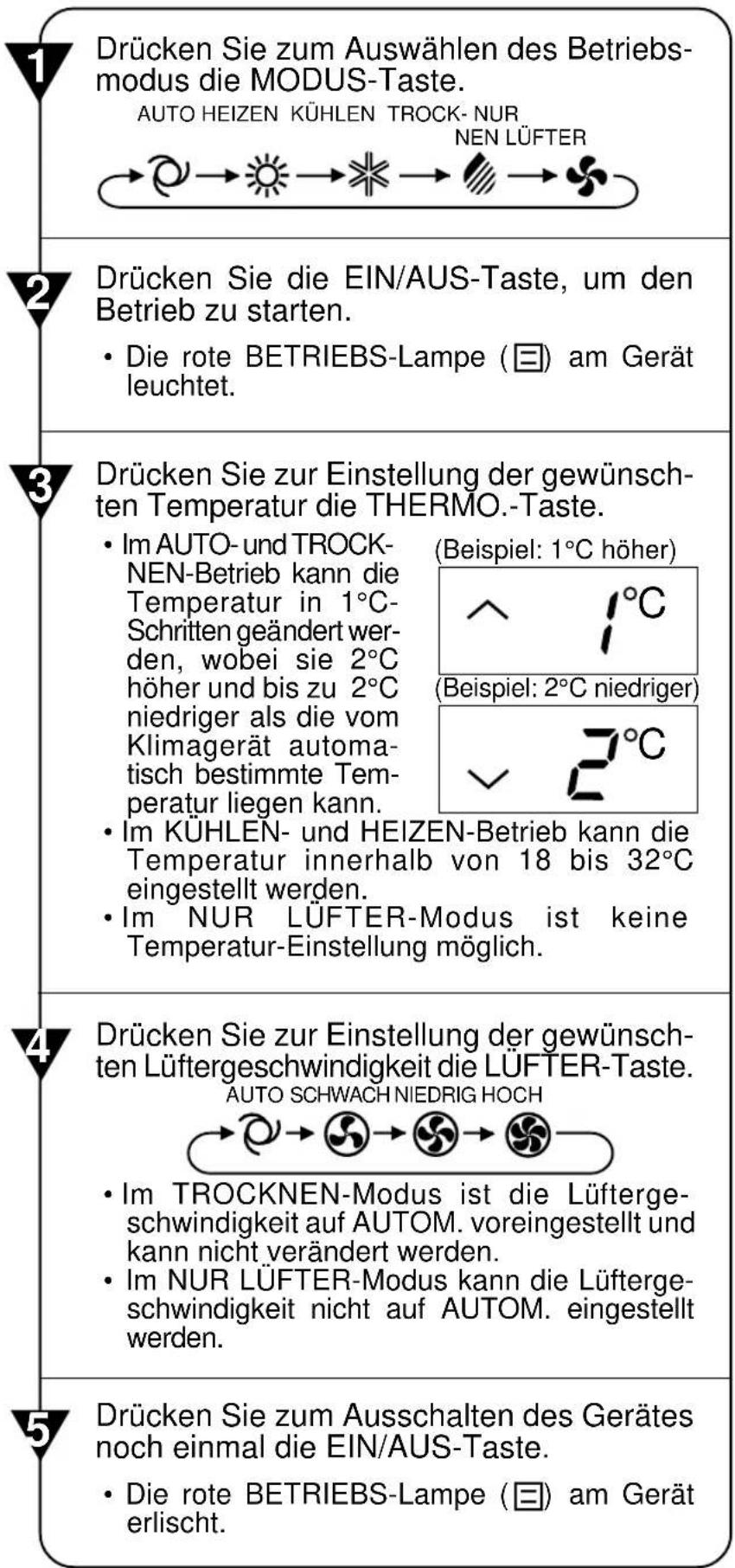
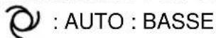
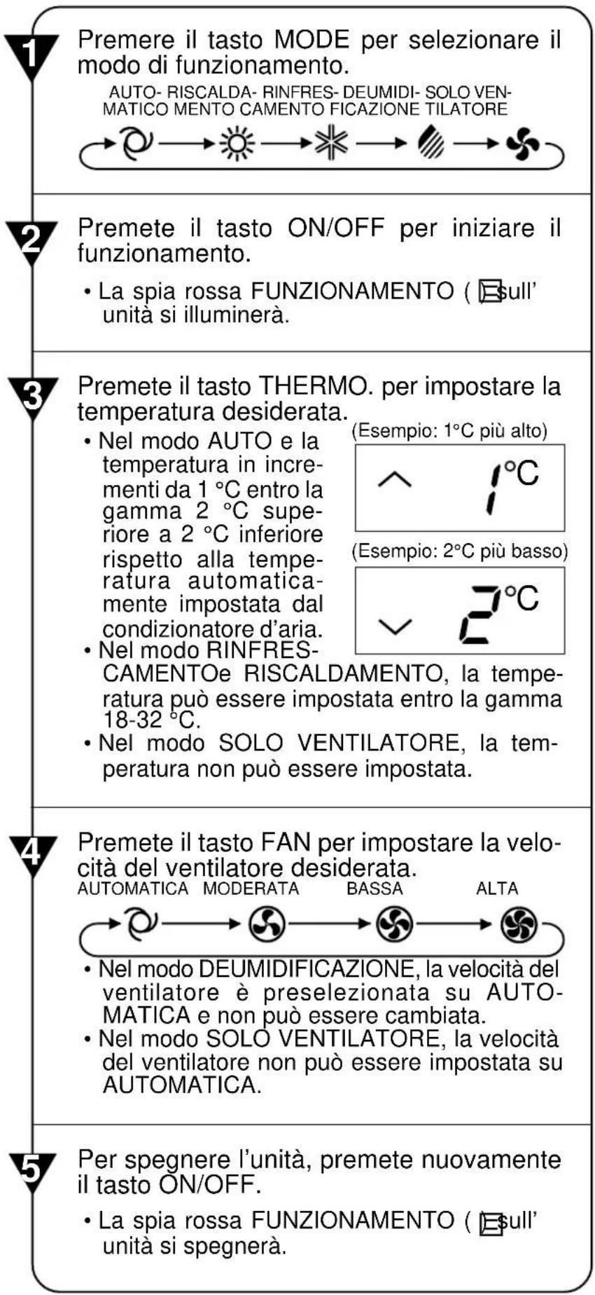
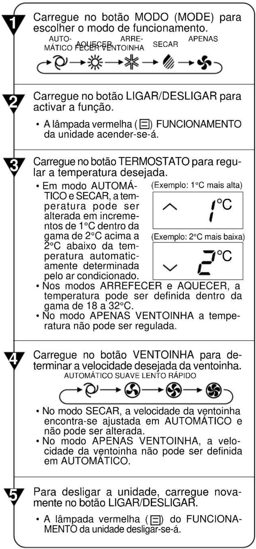
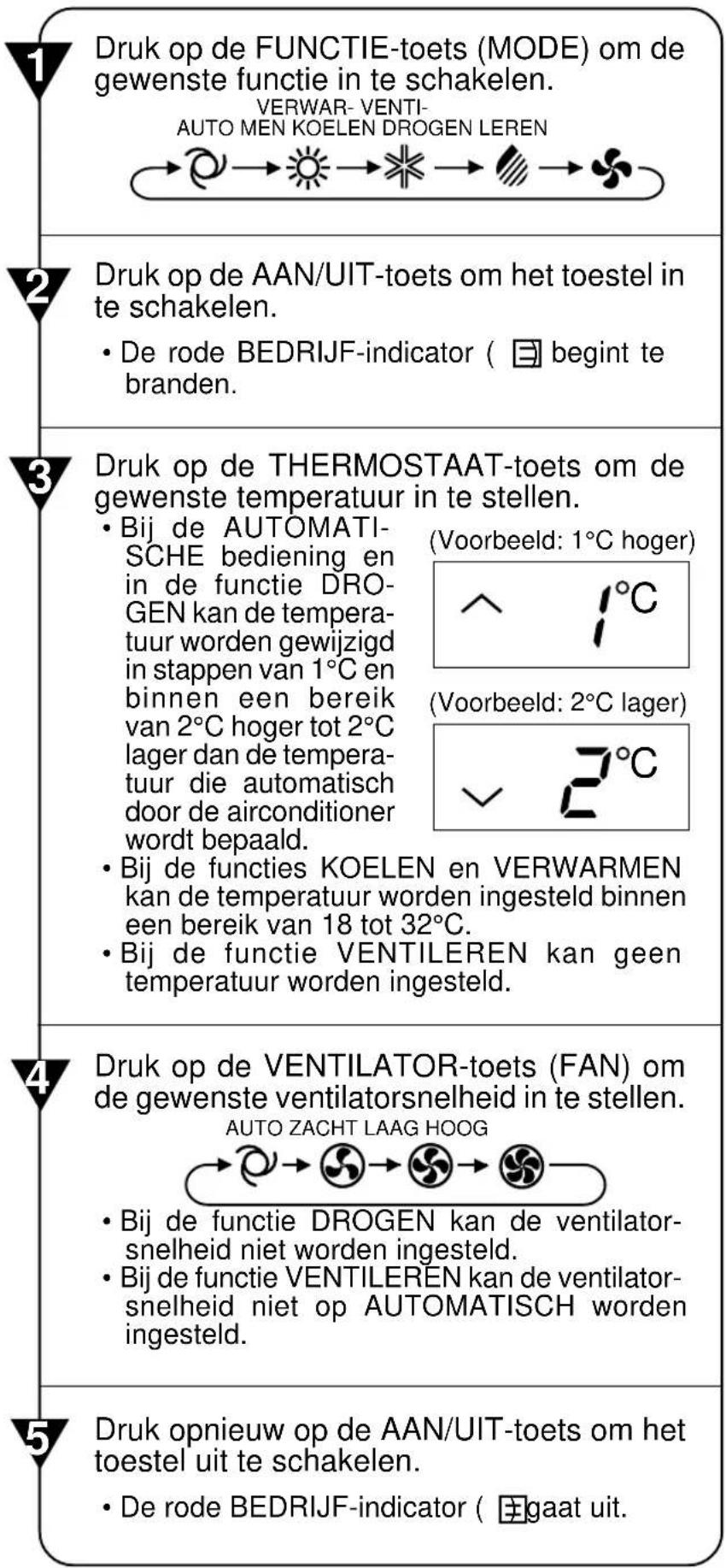
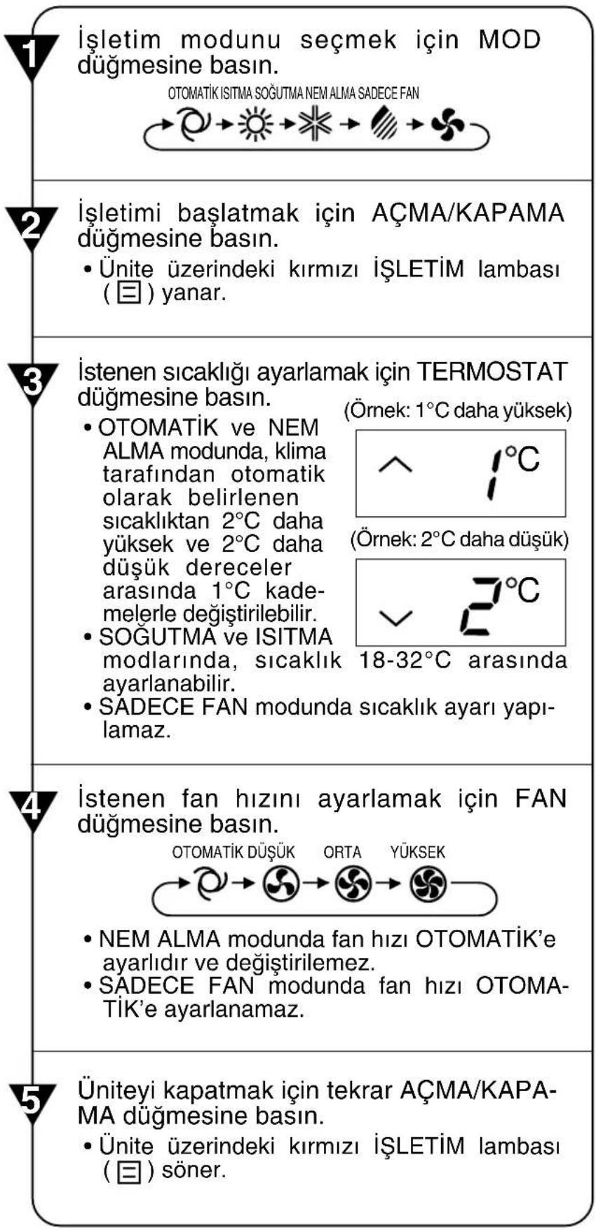
Press the MODE button to select the operation mode.
AUTO HEAT COOL DRY FAN ONLY

Press the ON/OFF button to start operation.
- The red OPERATION lamp ( ☐ on the unit will light.

Press the THERMO. button to set the desired temperature. (Example: 1°C higher)
• In the AUTO and DRY mode, the temperature can be changed in 1°C incerments within the range of 2°C higher to 2°C lower from the temperature automatically determined by the air conditioner.
(Example: 1°C higher)
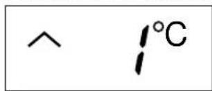
(Example: 2°C lower)
- In the COOL and HEAT modes, the temperature can be set within the range of 18 to 32^
- In the FAN ONLY mode, the temperature setting cannot be made.

Press the FAN button to set the desired fan speed.
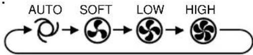
flowchart
graph LR
    A["AUTO"] --> B["SOFT"]
    B --> C["LOW"]
    C --> D["HIGH"]
- In the DRY mode, the fan speed is preset to AUTO and cannot be changed.
- In the FAN ONLY mode, the fan speed cannot be set to AUTO.

To turn off the unit, press the ON/OFF button again.
- The red OPERATION lamp ( ☑ on the unit will turn off.
TIPS ABOUT AUTO MODE
In the AUTO mode, the temperature setting and mode are automatically selected according to the room temperature and outdoor temperature when the unit is turned on.
Modes and Temperature Settings
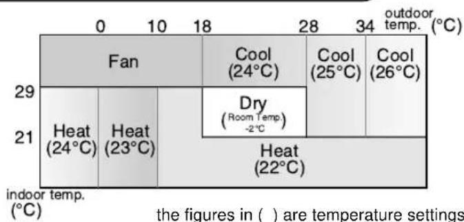
During operation, if the outdoor temperature changes, the temperature settings will automatically slide as shown in the chart.
MODE CHANGEOVER
During seasons when you need COOLING at daytime and HEATING at night, or if the room temperature should become extremely higher than the temperature setting, due to supplementary heating equipment, the mode will automatically switch between HEAT and COOL mode to keep the comfortable room temperature.
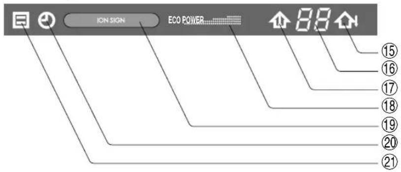
-TIPS ABOUT INDICATOR PANEL
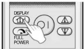
The indicator panel will change each time you press the DISPLAY button in the following manner.
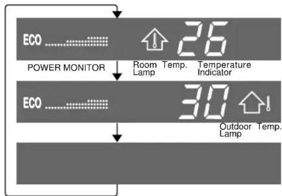
flowchart
graph TD
    A["ECO ......"] --> B["POWER MONITOR"]
    B --> C["Room Temp. 26 Lamp"]
    C --> D["Temperature Indicator"]
    E["ECO ......"] --> F["Outdoor Temp. 30 Lamp"]
    F --> G["Temp. 1"]
The room temperature and POWER MONITOR are displayed.
The outdoor temperature and POWER MONITOR are displayed.
No display.
POWER MONITOR
When the room temperature or the outdoor temperature is displayed, the POWER MONITOR will light up in 4 levels for COOL and HEAT modes (3 levels for DRY mode), to indicate the operation power. When the air conditioner is operating at maximum power in the COOL and HEAT modes, "Power" will light and "Eco" will turn off on the indicator panel.
NOTES:
- The displayed temperatures are rough estimates and may vary from the actual temperatures.
• Temperature display ranges
Room temperature: 0^ C \~ 40^ C (Lo is displayed when less than 0^ C and H, when higher than 40^ C)
Outdoor temperature: -9^ 45^ ( L_0 is displayed when less than -9^ and H, when higher than 45^ )
- -- is displayed during the first 90 seconds of operation while the temperatures are being detected.
- Only the room temperature can be displayed for 5 seconds when the unit is not in operation.
VERTICAL AIR FLOW DIRECTION
The air flow direction is automatically preset in each mode as follows for optimum comfort:
| COOL and DRY modes Horizontal air flow | |
| FAN ONLY and HEAT modes Diagonal air flow |
HOW TO ADJUST THE AIR FLOW DIRECTION
Press the SWING button on the remote control once.
- The vertical adjustment louvre will change its angle continuously.
Press the SWING button again when the vertical adjustment louvre is at the desired position.
- The louvre will stop moving within the range shown in the diagram.
- The adjusted position will be memorized and will be automatically set to the same position when operated the next time.
Adjustment range
COOL and DRY modes
FAN ONLY and HEAT modes
The adjustment range is narrower the SWING range in order to prevent condensation from dripping.
The range is wide so the air flow can be directed toward the floor.
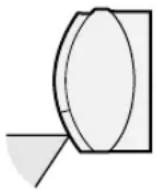
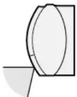
HORIZONTAL AIR FLOW DIRECTION
Hold the horizontal adjustment louvre as shown in the diagram and adjust the air flow direction.
natural_image
Illustration of a hand holding a curved object with horizontal lines and a ruler, no text or symbols present
CAUTION
Never attempt to adjust the vertical adjustment louvres manually.
- Manual adjustment of the vertical adjustment louvre can cause the unit to malfunction when the remote control is used for the adjustment.
- When the vertical adjustment louvre is positioned at the lowest position in the COOL or DRY mode for an extended period of time, condensation may result.
Do not adjust the horizontal adjustment louvre extremely to the right or left when operating the air conditioner with fan speed "SOFT" for an extended period of time.
Condensation may form on the louvres.
In this operation, the air conditioner works at maximum power to makes the room cool or warm so rapidly that you can use it just after you come home.
1 To activate the FULL POWER operation, press the FULL POWER button during operation.
• The remote control will display

- The temperature display will go off.
TO CANCEL
Press the FULL POWER button again.
- FULL POWER operation will also be cancelled when the operation mode is changed, or when the unit is turned off.
NOTES:
- You cannot use the FULL POWER operation during the FAN ONLY mode.
- You cannot set the temperature and fan speed during the FULL POWER operation.
ONE-HOUR OFF TIMER
When the ONE-HOUR OFF TIMER is set, the unit will stop operating after one hour.
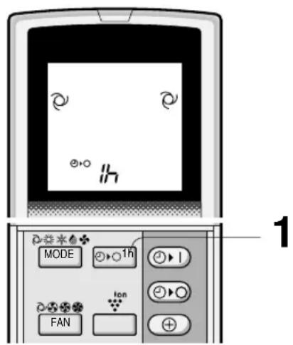
1 Press the ONE-HOUR OFF TIMER button.
- The remote control displays "
- The orange TIMER lamp ( ⚠ on the unit will light up.
- The unit will stop operating after one hour.
TO CANCEL
Press the TIMER CANCEL (SET/C) button.
- The orange TIMER lamp ( ) on the unit will turn off.
Or, turn the unit off by pressing the ON/OFF button.
- The red OPERATION lamp (☐) and the orange TIMER lamp (☑) on the unit will turn off.
NOTES:
- The ONE-HOUR OFF TIMER operation has priority over TIMER ON and TIMER OFF operations.
- When the ONE-HOUR OFF TIMER is set while the unit is not operating, the unit will operate for an hour with the formerly set condition.
- If you wish to operate the unit for another hour before the ONE-HOUR OFF TIMER activates, press the ONE-HOUR OFF TIMER button again during operation.
- If TIMER ON and/or TIMER OFF are set, TIMER CANCEL button cancels every setting.
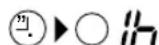
TIPS ABOUT PLASMACLUSTER OPERATION
The ionizer inside the air conditioner will release cluster ions, which are collective mass of positive and negative ions, into the room.
The cluster ions eliminate airborne mold fungus and deodorize / decompose odor-causing molecules.
flowchart
graph TD
    A["Mold fungus Odor"] --> B["Cluster ions"]
    B --> C["H2O"]
    D["Ionizer"] --> E["H2O"]
    style A fill:#ccc,stroke:#333
    style B fill:#ccc,stroke:#333
    style C fill:#999,stroke:#333
    style D fill:#ccc,stroke:#333
    style E fill:#999,stroke:#333
Eliminate, deodorize, decompose
AIR CLEAN OPERATION
Cluster ions released into the air will keep your room air clean.
Negative cluster ions which also exist in natural environment will be released into the air of your room in an increased rate, and help your physical and mental refreshment.
PLASMACLUSTER AUTO OPERATION
Allergen sensor and odor sensor will detect foul air in the room.
Air Clean Operation will be performed for one minute after the air conditioner is operated to detect foul air.
Air Clean Operation and Refreshing Operation will be selected and be performed automatically depending on the air foul degree.
Air Clean Operation will be performed when the air is detected to be foul, Refreshing Operation will be performed when the air is clean.
SELF CLEAN OPERATION
Plasmacluster Operation will be performed with FAN or HEAT mode, in order to reduce the growth of mold fungus, and dry inside of the air conditioner unit.
Utilize the operation at seasonal change over terms.
Mold fungus already grown can not be eliminated by this operation.
TIPS ABOUT ALLERGEN SENSOR AND ODOR SENSOR
What does Allergen Sensor react to?
- Alergen sensor reacts to mold fungus, plants/flowers pollen, dead ticks, dust, tobacco smoke etc.
What to Odor Sensor react to?
- Odor Sensor reacts to tobacco smoke, motor exhaust, odor emitted from animals, etc.
Allergen and Odor Sensor also may react to vapour of insecticides, cosmetics, alcohol, chemicals and the like, and to extreme change of temperature/humidity.
PLASMACLUSTER OPERATION
You can choose PLASMACLUSTER AUTO OPERATION, AIR CLEAN OPERATION or REFRESHING OPERATION
1 During operation, press the PLASMACLUSTER button to select the mode.
PLASMACLUSTER AUTO AIR CLEAN REFRESHING CANCEL
chemical
Diagram showing ion movement in a reaction mechanism with auto-catalyzed transformation• In the AIR CLEAN operation, the blue PLASMACLUSTER lamp on the unit will light up.
- In the REFRESHING operation, the green PLASMACLUSTER lamp on the unit will light up.
TO CANCEL
Press the PLASMACLUSTER button until PLASMACLUSTER symbol on the remote control display goes off.
- The PLASMACLUSTER lamp on the unit will turn off.
NOTES:
- Setting of the PLASMACLUSTER operation will be memorized and will operate in the same mode, the next time you turn on the air conditioner.
- To turn off the PLASMACLÜSTER lamp, press the DISPLAY button.
SELF CLEAN OPERATION
1 Press the SELF CLEAN button when the unit is not operating.
- The remote control displays " C".
- The red OPERATION lamp ( ☐ ) and the blue PLASMACLUSTER lamp on the unit will light up.
- The unit will stop operation after forty minutes.
- The remaining operation time will be indicated on the TEMPERATURE INDICATOR of the indoor unit in minute decrements.
TO CANCEL
Press the SELF CLEAN button.
Or, turn the unit off by pressing the ON/OFF button.
- The red OPERATION lamp (☐), the blue PLASMACLUSTER lamp and the TEMPERATURE INDICATOR on the unit will turn off.
NOTE:
- You cannot set the temperature, fan speed, air flow direction or timer setting during the SELF CLEAN operation.
TIMER OPERATION
NOTE:
Before setting the timer, make sure the clock is properly set with the current time.
TIMER OFF
1 Press the TIMER OFF ( - ) button.
2 The TIMER OFF indicator will blink; press the TIME ADVANCE or REVERSE buttons to set the desired time. (The time can be set in 10-minute increments.)
3 Point the remote control at the signal receiver window on the unit and press the TIMER SET (SET/C) button.
- The orange TIMER lamp ( ⏻ ) on the unit will light.
- The unit will generate a beep when it receives the signal.
When the TIMER OFF mode is set, the temperature setting is automatically adjusted to prevent the room from becoming excessively hot or too cold while you sleep. (Auto Sleep function)
COOL/DRY MODE:
- One hour after the time operation begins, the temperature setting rises 1^ higher than the original thermostat setting.
HEAT MODE:
- One hour after the timer operation begins, the temperature setting drops 3°C lower than the original thermostat setting.
NOTE:
- The Auto Sleep function will not activate during the FAN ONLY mode.
TO CANCEL TIMER MODE
Press the TIMER CANCEL (SET/C) button.
- The orange TIMER lamp ( ⏻ ) on the unit will turn off.
• The current clock time will be displayed on the remote control.
NOTE:
- If any TIMER ON, TIMER OFF and ONE-HOUR OFF TIMER are set, the TIMER CANCEL button cancels all settings.
TO CHANGE TIME SETTING
Cancel the TIMER setting first, then set it again.
TIMER ON
1 Press the TIMER ON ( ⏻ button.
2 The TIMER ON indicator will blink; press the TIME ADVANCE or REVERSE buttons to set the desired time. (The time can be set in 10-minute increments.)
3 Point the remote control at the signal receiver window on the unit and press the TIMER SET (SET/C) button.
- The orange TIMER lamp ( ⏻ ) on the unit will light.
- The unit will generate a beep when it receives the signal.
4 Select the operation condition.
- The unit will turn on prior to the set time to allow the room to reach the desired temperature by the programmed time. (Awaking function)
COMBINED USE OF ON AND OFF TIMERS
You can use the ON and OFF timers in combination.
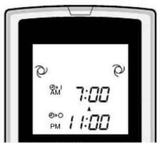
Example:
To stop operation at 11:00 p.m. and resume operation (With the same mode and temperature settings) to bring the room temperature to the desired level by 7:00 a.m.
1 Set the TIMER OFF to 11:00 p.m. during operation.
2 Set the TIMER ON to 7:00 a.m.
The arrow (▼ or ▲) between the TIMER ON indicator and the TIMER OFF indicator shows which timer will activate first.
NOTES:
- You cannot programme the ON-TIMER and OFF-TIMER to operate the unit at different temperatures or other settings.
- Either timer can be programmed to activate prior the other.
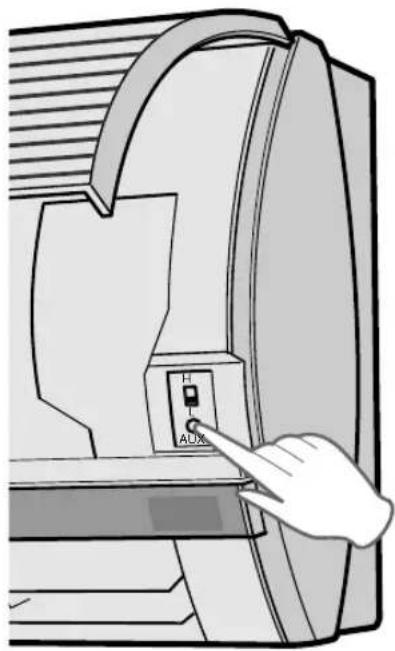
AUXILIARY MODE
Use this mode when the remote control is not available.
TO TURN ON
Lift the front panel of the indoor unit and press the AUX. button on the operation panel.
- The red OPERATION lamp (☐) on the unit will light and the unit will start operating in the AUTO mode.
- The fan speed and temperature setting are set to AUTO.
TO TURN OFF
Press the AUX. button on the operation panel again.
- The red OPERATION lamp ( ☐ ) on the unit will turn off.
NOTE:
If the AUX. button is pressed during normal operation, the unit will turn off.
natural_image
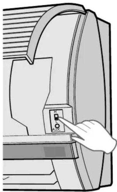
Illustration of a hand pressing a button labeled 'AUX' on a computer monitor (no text or symbols beyond basic labels)POWER SELECTOR (only for model AY-XP13CE)
When installing the air-conditioner to a residence with small electrical current capacity, switch the POWER SELECTOR to "L". The air conditioner will operate with reduced power, and the circuit breaker tripping or fuse blowing caused by excess power consumption can be avoided.
• COOLING or HEATING capacity will be reduced when operating at "L" setting.
- Consult your dealer or qualified technician if continuous breaker tripping or fuse blowing is experienced even by switching to "L" setting.
| AY-XP13CE | |
| Maximum ampere at "H" setting | 12A |
| Maximum ampere at "L" setting | 8A |
ADDITIONAL NOTES ON OPERATION
D.B. = Dry-bulb
W.B. = Wet-bulb
- The built-in protective device may prevent the unit from operating when used out of this range.
- Condensation may form on the air outlet if the unit operates continuously in the COOL or DRY mode when humidity is over 80 percent.
WHEN POWER FAILURE OCCURS
This air conditioner has a memory function to store settings when a power failure occurs. After power recovery, the unit will automatically re-start in the same settings which were active before the power failure, except for timer settings.
If the timers were set before a power failure, they will need to be re-set after power recovery.
PREHEATING FUNCTION
In the HEAT operation, the indoor fan may not start for two to five minutes after the unit is turned on to prevent cold air from blowing out of the unit.
DE-ICING FUNCTION
- When ice forms on the heat exchanger in the outdoor unit during the HEAT operation, an automatic de-icer provides heat for about 5 to 10 minutes to remove the ice. During de-icing, the inside and outside fans stop operating.
- After de-icing is completed, the unit automatically resumes operation in the HEAT mode.
HEATING EFFICIENCY
- The unit employs a heat pump that draws heat from the outside air and releases it into the room. The outside air temperature therefore greatly affects the heating efficiency.
- If the heating efficiency is reduced due to low outside temperatures, use an additional heater.
- It takes time to warm up and heat the entire room because of the forced air circulation system.
TIPS ON SAVING ENERGY
Below are some simple ways to save energy when you use your air conditioner.
SET THE CORRECT TEMPERATURE
- Setting the thermostat 1°C higher than the desired temperature in the COOL mode and 2°C lower in the HEAT mode will save approximately 10 percent in power consumption.
- Setting the temperature lower than necessary during cooling operation will result in increased power consumption.
BLOCK DIRECT SUNLIGHT AND PREVENT DRAFTS
- Blocking direct sunlight during cooling operation will reduce power consumption.
- Close the windows and doors during cooling and heating operations.
SET PROPER AIR FLOW DIRECTION TO OBTAIN THE BEST AIR CIRCULATION
KEEP FILTER CLEAN TO ENSURE THE MOST EFFICIENT OPERATION MAKE MOST OF THE TIMER OFF FUNCTION
DISCONNECT THE POWER CORD WHEN THE UNIT IS NOT USED FOR AN EXTENDED PERIOD OF TIME
- The indoor unit still consumes a small amount of power when it is not operating.
Be sure to disconnect the power cord from the wall outlet or turn off the circuit breaker before performing any maintenance.
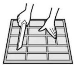
CLEANING THE FILTERS
The air filters should be cleaned every two weeks.

natural_image
Illustration of hands using a tool to cut or spread on a grid (no text or symbols)
1 TURN OFF THE UNIT
2 REMOVE THE FILTERS
①Lift the open panel.
②Push the air filters up slightly to unlock them.
③Pull the air filters down to remove them.
3 TAKE OFF THE DEODORANT FILTER AND THE DUST COLLECTION FILTER FROM THE AIR FILTERS
4 CLEAN THE FILTERS
Use a vacuum cleaner to remove dust. If the filters are dirty, wash them with warm water and a mild detergent. Dry filters in the shade before reinstalling.
5 REINSTALL THE DEODORANT FILTER AND THE DUST COLLECTION FILTER
6 REINSTALL THE FILTERS
①Reinstall the filters in the original positions.
②Close the front panel.
③Push the arrow-marked of the panel firmly to lock it in place.
CLEANING THE UNIT AND THE REMOTE CONTROL
- Wipe them with a soft cloth.
- Do not directly splash or pour water on them. We can cause electrical shock or equipment damage.
- Do not use hot water, thinner, abrasive powders or strong solvents.
MAINTENANCE AFTER AIR CONDITIONER SEASON
1 Operate the unit in the SELF CLEAN OPERATION to allow the mechanism to thoroughly dry.
2 Stop the operation and unplug the unit. Turn off the circuit breaker, if you have one exclusively for the air conditioner.
3 Clean the filters, then reinstall them.
MAINTENANCE BEFORE AIR CONDITIONER SEASON
1 Make sure that the air filters are not dirty.
2 Make sure that nothing obstructs the air inlet or outlet.
3 Check the outdoor mounting rack periodically for wear and to make sure it is firmly in place.
CLEANING THE DEODORANT FILTER (GREEN)
The filter should be cleaned every 3\~6 months
natural_image
Illustration of hands handling a grid-patterned device with a mesh coil (no text or symbols)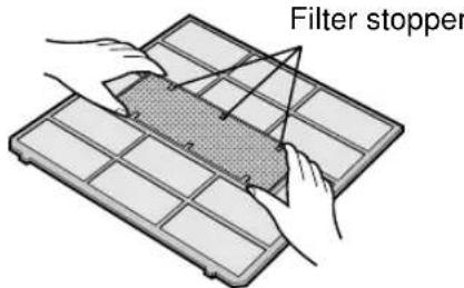
1 REMOVE THE AIR FILTERS
2 CLEAN THE DEODORANT FILTER
1 Take off the deodorant filter from the air filters.
2 Soak the deodorant filter in mild detergent dilution for 10 to 20 minutes.
Rinse thoroughly with water, dry completely under sunlight.
3 Set the clean deodorant filter under the filter stoppers located on the air filters.
3 REINSTALL THE AIR FILTERS
NOTE:
- Replacement is necessary at the interval of 3 years, as the deodorising effect will deteriorate. The new filters are available at your nearest dealer.
Replacement filter: Type AZ-F910C
CHANGING THE DUST COLLECTION FILTER (GRAY)
The filter should be changed every 3\~6 months
1 REMOVE THE AIR FILTERS
2 CHANGE THE DUST COLLECTION FILTER
1 Take off the old dust collection filter from the air filters.
2 Set the new dust collection filter, the black side facing upward, under the filter stoppers located on the air filters.
3 REINSTALL THE AIR FILTERS
NOTE:
- The dirty dust collection filter is not washable for reuse. The new filters are available at your nearest dealer.
Replacement filter: Type AZ-F900C
BEFORE CALLING FOR SERVICE
The following conditions do not denote equipment malfunctions
| UNIT DOES NOT OPERATEThe unit will not operate if it is turned on immediately after it is turned off. The unit will not operate immediately after the mode is changed. This is to protect the internal mechanisms. Wait 3 minutes before operating the unit. | SWISHING NOISEThe soft, swishing noise is the sound of the refrigerant flowing inside the unit. |
| WATER VAPOURIn the COOL and DRY operation, water va-pour can sometimes be seen at the air outlet due to the difference between the room air temperature and the air discharged by the unit.In the HEAT operation, water vapour may flow out of the outdoor unit during de-icing. | |
| UNIT DOES NOT SEND OUT WARM AIRThe unit is preheating or de-icing. | |
| ODORSCarpet and furniture odors that entered into the unit and the air conditioner's inner component odors at the early stage of installation may be sent out from the unit. | THE OUTDOOR UNIT DOES NOT STOPAfter stopping the operation, the outdoor unit will rotate its fan for about a minute to cool down the unit. |
| CRACKING NOISEThe unit may produce a cracking noise. This sound is generated by the friction of the front panel and other components expanding or connecting due to a temperature change. | ODOR EMITTED FROM THE PLASMACLUSTER AIR OUTLETThis is the smell of ozone generated from the ionizer. Density of the ozone is very little, hav-ing no adverse effect over your health. The ozone released into the air will decompose soon, and its density in the room will not increase. |
| A LOW BUZZ NOISE EMITTEDThis is a sound emitted when the unit is generating ion clusters. | |
| During PLASMACLUSTER AUTO OPERATION, the air conditioner operates in the REFRESHING OP-ERATION even when there is odor in the room.In case for example, when the room is full of tobacco smokes before the air conditioner is turned on, the ODOR SENSOR may become unreactive. | |
If the unit appears to be malfunctioning, check the following points before calling for service.
| IF THE UNIT FAILS TO OPERATE |
| Check to see if the circuit breaker has tripped or the fuse has blown. |
| IF THE UNIT FAILS TO COOL (OR HEAT) THE ROOM EFFECTIVELY | ||
| Check the filters. If dirty, clean them. | Check the outdoor unit to make sure nothing is blocking the air inlet or outlet. | Check the thermostat is proper setting. |
| Make sure windows and doors are closed tightly. | A large number of people in the room can prevent the unit from achieving the desired temperature. | Check whether any heat-generating appliances are operating in the room. |
| IF THE UNIT FAILS TO RECEIVE THE REMOTE CONTROL SIGNAL | ||
| Check whether the remote control batteries have become old and weak. | Try to send the signal again with the remote control pointed properly towards the unit's signal receiver window. | Check whether the remote control batteries are installed with the polarities properly aligned. |
Please call for service when OPERATION Lamp, TIMER Lamp and TEMPERATURE INDICATOR on the indicator panel blink.
DEUTSCH

STAUBAUFFANGFILTER (grau)
natural_image
Illustration of a wall-mounted air conditioner with a digital display and pointer, no text or symbols present
VORSICHT
Beispiel: 17:00 Uhr
natural_image
Illustration of a hand holding a curved object with horizontal lines and a small rectangular object at the base (no text or symbols)
VORSICHT
chemical
Diagram illustrating the formation of hydrogen peroxide (H2O) from Schimmelpilze Geruch and Ionisator, showing electron transfer and water dissolution steps.PLASMACLUSTER-BETRIEB
chemical
Electron transfer reaction diagram showing ion movement from negative to positive and negative ions via auto electron transferHINWEIS:
Beispiel:
natural_image
Illustration of a computer monitor with an 'AUX' button and a hand pointing to it (no text or symbols on the device itself)
natural_image
Illustration of hands using a tool to cut or spread a grid on a grid-patterned surface (no text or symbols)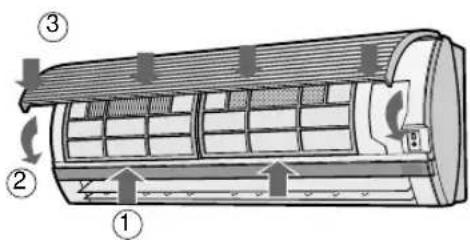
1 SCHALTEN SIE DAS GERÄT AUS.
2 ENTNEHMEN SIE DIE FILTER.
natural_image
Illustration of hands handling a grid-patterned object on a rectangular tray (no text or symbols)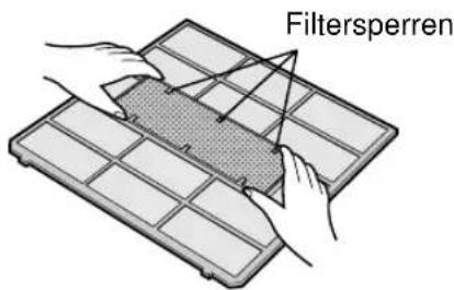
1 NEHMEN SIE DIE LUFTFILTER HERAUS.
2 REINIGEN SIE DEN DESODORIERUNGSFILTER.
① FILTRE A POUSSIERE (non lavable)
② FILTRE DESODORISANT (lavable)
①EMETTEUR
② AFFICHAGE (Affichage à cristaux liquides)
③ Touche D'AFFICHAGE (DISPLAY)
④Touche PLEIN REGIME (FULL POWER)
⑤ Touche ON/OFF
⑥Touche Thermostat. (THERMO)
⑦Touche MODE
⑧Touche de VENTILATEUR (FAN)
⑨ Touche D'ARRET APRES UNE heure (ONE-HOUR OFF TIMER)
⑩ Touche DE MISE EN MARCHE DE LA MINUTERIE (TIMER ON)
⑪ Touche D'ARRET DE LA MINUTERIE (TIMER OFF)
⑫Touche PLASMACLUSTER
⑬Touche D'AVANCE DU TEMPS (TIME ADVANCE)
⑭Touche DE RECUL DU TEMPS (TIME REVERSE)
⑮ Touche de nettayage automatique (SELF CLEAN)
⑯ Touche DE REGLAGE DE MINUTERIE/D'ANNULATION PLEIN REGIME (SET/CANCEL)
⑰Indique que le COMPARTIMENT DES PILES est en dessous de cette marque
⑱ Touche D'HORLOGE (CLOCK)
⑲Touche SWING
AFFICHAGE L.C.D. DE LA TELECOMMANDE


natural_image
Illustration of a wall-mounted air conditioner with a digital display and pointer, no text or symbols present
ATTENTION
natural_image
Illustration of a hand holding a ruler on a curved surface with horizontal lines (no text or symbols)
ATTENTION
REMARQUE :
Exemple :
natural_image
Illustration of a computer monitor with an 'AUX' button and a hand pointing to it (no text or symbols on the device itself)SELECTEUR D'ALIMENTATION(AY-XP13CE seulement)

natural_image
Illustration of hands using a tool to cut or spread a grid on a 3x3 grid (no text or symbols)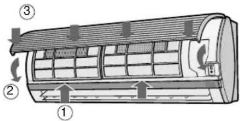
natural_image
Illustration of hands handling a grid-patterned device with a mesh coil (no text or symbols)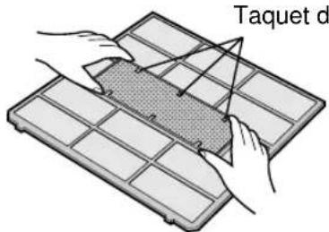
1 RETIRER LES FILTRES A AIR
2 NETTOYER LE FILTRE DESODORISANT

UNIDAD EXTERIOR
⑲SÍMBOLO DEL PLASMACLUSTER
natural_image
Illustration of a wall-mounted air conditioner with a digital display and pointer, no text or symbols present
PRECAUCIÓN

natural_image
Illustration of a hand pressing down on a curved surface with horizontal lines and a scale bar (no text or symbols)
PRECAUCIÓN
chemical
Diagram showing ion movement in a reaction mechanism with labeled positive and negative chargesnatural_image
Illustration of a hand pressing a button labeled 'AUX' on a computer monitor (no text or symbols beyond basic labels)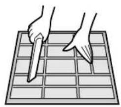
natural_image
Illustration of hands using a tool to cut or spread a grid on a 3x3 grid (no text or symbols)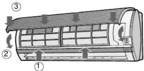
1 DESCONECTE LA UNIDAD
2 SAQUE LOS FILTROS
natural_image
Illustration of two hands installing or adjusting a grid-patterned plastic tray (no text or symbols)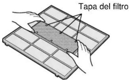
1 SAQUE LOS FILTROS DE AIRE
2 LIMPIE EL FILTRO DESODORANTE

①FILTRO DI ACCUMULO POLVERE (non lavabile)
②FILTRO DEODORANTE (lavabile)
③Presa (d'aria)
④Pannello aperto
⑤ Filtri dell'aria
FILTRO DI ACCUMULO POLVERE (grigio)
natural_image
Illustration of a wall-mounted air conditioner with a digital display and pointer, no text or symbols present
PRECAUZIONI
natural_image
Illustration of a hand holding a ruler with measurement markings (no text or symbols present)
PRECAUZIONI
NOTA:
Esempio:
natural_image
Illustration of a hand pressing a button labeled 'AUX' on a computer monitor (no text or symbols beyond the label)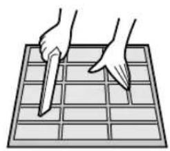
natural_image
Illustration of hands using a tool to cut or spread a grid on a rectangular surface (no text or symbols)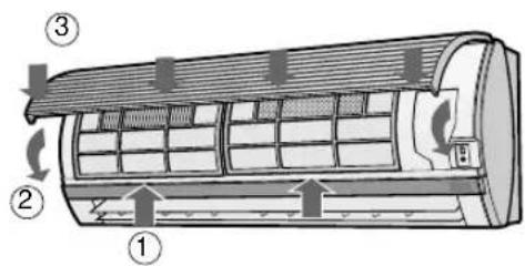
1 SPEGNETE L'UNITA'
2 RIMUOVETE I FILTRI
natural_image
Illustration of hands handling a grid-patterned device with a mesh coil (no text or symbols)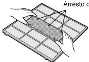
1 ESTRAETE I FILTRI AD ARIA
2 PULITE IL FILTRO DEODORANTE

UNIDADE EXTERIOR
FILTRO DE RECOLHA DE POEIRA (cinzento)
Instale o lado negro virado para cima.
FILTRO DESODORIZANTE
(verde)
natural_image
Illustration of hands assembling a battery grid (no text or symbols)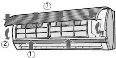
NOTAS:
natural_image
Illustration of a wall-mounted air conditioner with a digital display and pointer, no text or symbols present
ATENÇÃO
natural_image
Illustration of a hand holding a ruler on a curved surface with horizontal lines (no text or symbols)
ATENÇÃO
chemical
Diagram showing ion movement in a reaction mechanism with autoantibody, showing electron transfer and charge distributionNOTA:
natural_image
Illustration of hands using a tool to cut or spread a grid on a 3x3 grid (no text or symbols)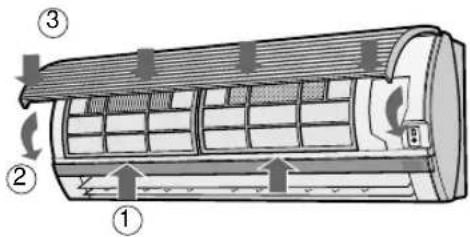
1 DESLIGAR A UNIDADE
2 RETIRAR OS FILTROS
natural_image
Illustration of hands installing or adjusting a grid-patterned plastic tray (no text or symbols)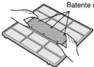
1 REMOVA OS FILTROS DE AR
2 LIMPE O FILTRO DESODORIZANTE

natural_image
Illustration of a wall-mounted air conditioner with a digital display and pointer, no text or symbols present
ΠΡΟΣΟΧΗ
1
natural_image
Illustration of a hand holding a ruler above a curved surface with horizontal lines (no text or symbols)
ΠΡΟΣΟΧΗ
1
ΓΙΑ ΑΚΥΡΩΣΗ
ΣΗΜΕΙΩΣΗ:
natural_image
Illustration of a hand pressing a button labeled 'AUX' on a computer monitor (no text or symbols beyond basic labels)natural_image
Illustration of a hand pressing a button labeled 'A1X' on a computer screen (no text or symbols beyond the label)
natural_image
Illustration of hands using a tool to cut or spread on a grid (no text or symbols)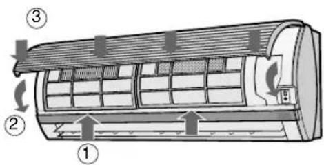
natural_image
Illustration of hands handling a grid-patterned device with a mesh coil (no text or symbols)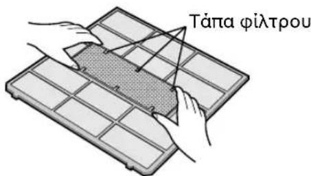
WAARSCHUWINGEN BIJ DE PLAATSING/INSTALLATIE

①STOFOPVANGFILTER (niet-wasbaar)
②ONTGEURINGSFILTER (wasbaar)
③Inlaat (lucht)
④Opklapbaar paneel
⑤Luchtfilters
STOFOPVANGFILTER (grijs)
natural_image
Illustration of a wall-mounted air conditioner with a digital display and pointer, no text or symbols present
LET OP
natural_image
Illustration of a hand holding a curved object with horizontal lines and a ruler, no text or symbols present
LET OP
natural_image
Simple cartoon-style illustration of a tablet device with a face and abstract symbols (no text or readable labels)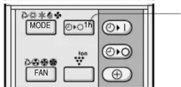
1 Druk op de ÉÉN-UURS TIMER-toets.
chemical
Diagram showing ion movement in a reaction mechanism with autoantibody, showing electron transfer and ion evolutionKOELEN/DROGEN-FUNCTIE:
OPMERKING:
Voorbeeld:
natural_image
Illustration of a hand pressing a button labeled 'AUX' on a computer monitor (no text or symbols beyond labels)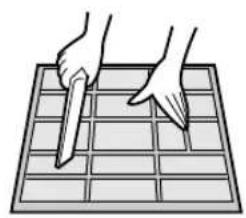
natural_image
Illustration of hands using a tool to cut or spread on a grid (no text or symbols)
1 SCHAKEL HET TOESTEL UIT
2 VERWIJDER DE FILTERS

DIŞ ÜNİTE
TOZ TOPLAMA FİLTRESİ (gri)
natural_image
Illustration of a wall-mounted air conditioner with a digital display and a power cord emitting light (no text or symbols)
UYARI
natural_image
Illustration of a hand holding a ruler on a curved surface with horizontal lines (no text or symbols)
UYARI
BİR SAAT SONRA KAPANMA AYARI
chemical
Diagram showing ion movement in a reaction mechanism with autoantibody, involving proton and electron symbolsNOT:
natural_image
Illustration of a hand inserting a button labeled 'AUX' into a device (no text or symbols beyond the label)
natural_image
Illustration of hands using a tool to cut or spread on a grid (no text or symbols)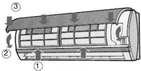
1 ÜNİTEYİ KAPATIN
2 FILTRELERİ ÇIKARIN
①Ön paneli açın.
natural_image
Illustration of hands handling a grid-patterned device (no text or symbols visible)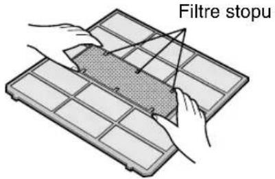
1 HAVA FILTRELERİNİ ÇIKARIN
2 KOKU GİDERME FİLTRESİNİ TEMİZLEYİN

- AY-XP08CE AY-XP10CE AY-XP13CE
- CONTENTS
- PRECAUTIONS
- WARNINGS FOR USE
- WARNINGS FOR INSTALLATION / REMOVAL / REPAIR
- CAUTIONS FOR USE
- CAUTIONS FOR LOCATION / INSTALLATION
- L.C.D. REMOTE CONTROL DISPLAY
- SETTING DUST COLLECTION FILTER AND DEODORANT FILTER
- Take out the air filters.
- Set the dust collection filter and the deodorant filter under the filter stoppers located on the air filter.
- Reinstall the air filters
- LOADING BATTERIES Use two size-AAA (R03) batteries.
- NOTES:
- HOW TO USE THE REMOTE CONTROL
- CAUTION
- SET CURRENT CLOCK TIME
- NOTE:
- TIPS ABOUT AUTO MODE
- MODE CHANGEOVER
- -TIPS ABOUT INDICATOR PANEL
- POWER MONITOR
- VERTICAL AIR FLOW DIRECTION
- HOW TO ADJUST THE AIR FLOW DIRECTION
- Adjustment range
- HORIZONTAL AIR FLOW DIRECTION
- TO CANCEL
- ONE-HOUR OFF TIMER
- TIPS ABOUT PLASMACLUSTER OPERATION
- AIR CLEAN OPERATION
- PLASMACLUSTER AUTO OPERATION
- SELF CLEAN OPERATION
- TIPS ABOUT ALLERGEN SENSOR AND ODOR SENSOR
- What does Allergen Sensor react to?
- What to Odor Sensor react to?
- PLASMACLUSTER OPERATION
- You can choose PLASMACLUSTER AUTO OPERATION, AIR CLEAN OPERATION or REFRESHING OPERATION
- TIMER OPERATION
- TIMER OFF
- COOL/DRY MODE:
- HEAT MODE:
- TO CANCEL TIMER MODE
- TO CHANGE TIME SETTING
- TIMER ON
- COMBINED USE OF ON AND OFF TIMERS
- Example:
- AUXILIARY MODE
- TO TURN ON
- TO TURN OFF
- POWER SELECTOR (only for model AY-XP13CE)
- ADDITIONAL NOTES ON OPERATION
- WHEN POWER FAILURE OCCURS
- PREHEATING FUNCTION
- DE-ICING FUNCTION
- HEATING EFFICIENCY
- TIPS ON SAVING ENERGY
- SET THE CORRECT TEMPERATURE
- BLOCK DIRECT SUNLIGHT AND PREVENT DRAFTS
- SET PROPER AIR FLOW DIRECTION TO OBTAIN THE BEST AIR CIRCULATION
- KEEP FILTER CLEAN TO ENSURE THE MOST EFFICIENT OPERATION MAKE MOST OF THE TIMER OFF FUNCTION
- DISCONNECT THE POWER CORD WHEN THE UNIT IS NOT USED FOR AN EXTENDED PERIOD OF TIME
- CLEANING THE FILTERS
- CLEANING THE UNIT AND THE REMOTE CONTROL
- MAINTENANCE AFTER AIR CONDITIONER SEASON
- MAINTENANCE BEFORE AIR CONDITIONER SEASON
- CLEANING THE DEODORANT FILTER (GREEN)
- CHANGING THE DUST COLLECTION FILTER (GRAY)
- BEFORE CALLING FOR SERVICE
- DEUTSCH
- VORSICHT
- PLASMACLUSTER-BETRIEB
- HINWEIS:
- Beispiel:
- AFFICHAGE L.C.D. DE LA TELECOMMANDE
- ATTENTION
- REMARQUE :
- Exemple :
- SELECTEUR D'ALIMENTATION(AY-XP13CE seulement)
- PRECAUCIÓN
- PRECAUZIONI
- NOTA:
- Esempio:
- NOTAS:
- ATENÇÃO
- DESLIGAR A UNIDADE
- RETIRAR OS FILTROS
- ΠΡΟΣΟΧΗ
- 1
- ΓΙΑ ΑΚΥΡΩΣΗ
- ΣΗΜΕΙΩΣΗ:
- WAARSCHUWINGEN BIJ DE PLAATSING/INSTALLATIE
- LET OP
- KOELEN/DROGEN-FUNCTIE:
- OPMERKING:
- Voorbeeld:
- UYARI
- BİR SAAT SONRA KAPANMA AYARI
- NOT:
Brand : SHARP
Model : AEX08BEC
Category : Air-conditioner