8000 BTU - Air Conditioning CONRAD - Free user manual and instructions
Find the device manual for free 8000 BTU CONRAD in PDF.


User questions about 8000 BTU CONRAD
0 question about this device. Answer the ones you know or ask your own.
Ask a new question about this device
Download the instructions for your Air Conditioning in PDF format for free! Find your manual 8000 BTU - CONRAD and take your electronic device back in hand. On this page are published all the documents necessary for the use of your device. 8000 BTU by CONRAD.
USER MANUAL 8000 BTU CONRAD
www.business.conrad.at
text_image
Technical diagram of a dual-chamber air conditioner unit with numbered labels pointing to internal components.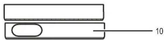
natural_image
Simple line drawing of two rectangular blocks with a central oval and a horizontal line labeled '10' (no text or symbols beyond the number)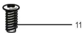
text_image
12 13
natural_image
Simple line drawing of a bowl with a side panel and a horizontal line extending from the center (no text or symbols)b) Bedienfeld
text_image
14 15 16 17 18 19 20 21 22 23 24 WF COMP HIGH LOW TIMER SLEEP COOL DEHUM FAN POWER 2526272829303132c) Fernbedienung
text_image
41 40 39 38 33 34 35 36 37natural_image
Diagram showing a cylindrical object with internal components and directional arrows indicating rotation or movement (no text or symbols)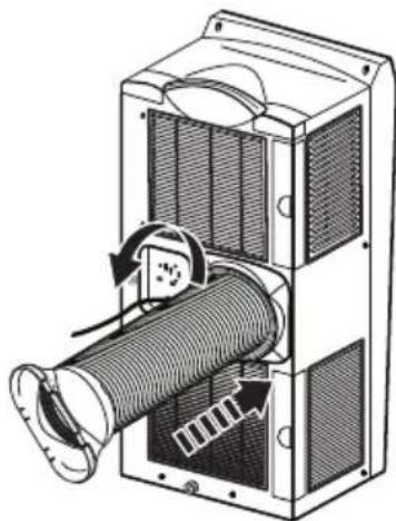
natural_image
Diagram of a mechanical device with internal components and airflow direction arrows (no text or symbols)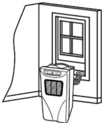
natural_image
Line drawing of a door with a portable air conditioner unit and a window on the door (no text or symbols)natural_image
Technical line drawing of a mechanical device with a curved pipe or pipe fitting (no text or symbols)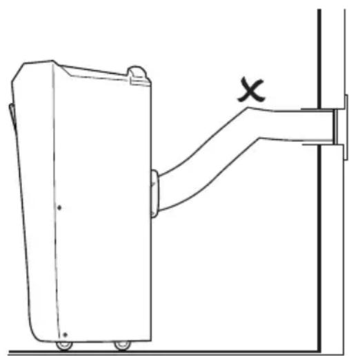
natural_image
Technical line drawing of a mechanical device with a bracket and mounting bracket (no text or symbols)Abb. D Abb. E
- Introduction ...... 18
- Scope of delivery ....18
- Intended use 19
- Explanation of symbols....19
- Operating elements ....20
a) Mobile air-conditioning unit....20
b) Operating panel ...... 21
c) Remote control .... 21
- Safety information....22
a) People / Product....22
b) Batteries / Rechargeable batteries ..... 23
c) Miscellaneous .....23
- Start-up operation....24
a) Unpacking and inspection ....24
b) Assembly 24
c) Remote control ....25
- Operation ...... 26
a) Switching on and off 26
b) Cooling (COOL)....26
c) Dehumidify (DEHUM)....26
d) Fan (FAN)....26
e) Timer (TIMER)....27
f) Sleep mode (SLEEP) 27
-
Troubleshooting .....28
-
Maintenance and cleaning....28
a) Casing ....28
b) Cleaning air filters....28
c) Emptying water container .... 29
d) Storage....29
- Disposal 30
a) Product....30
b) (Rechargeable) Batteries....30
- Technical specifications .... 30
a) Air-conditioning unit (item no. 396453)....30
b) Air-conditioning unit (item no. 396454)....31
c) Remote control .... 31
1. Introduction
Dear customer,
We thank you for the purchase of this product.
This product complies with the statutory national and European requirements. In order to maintain the condition and to ensure a hazard free operation, you-the user-must comply with this operating manual!

Please read this complete operating manual prior to operating the product and comply with all operating and safety instructions.
All company names and product names are trademarks of their respective owners. All rights reserved.
In case of technical questions please contact:
Germany: Phone: +49 9604 / 40 88 80
Fax: +49 9604 / 40 88 48
Mon. to Thur. 8.00am to 4.30pm, Fri 8.00am to 2.00pm
2. Scope of delivery
- Air-conditioning unit
- Remote control
- Flexible exhaust hose
- Adapter for exhaust hose
- Extendable window guide (inner/outer part)
- 6 x crosshead screws
3. Intended use
The mobile air-conditioning unit is designed to cool, ventilate, and dehumidify interior rooms. Always place the product on a level, sturdy, and dry surface.
The device is designed for domestic use. The product is not suitable for commercial use.
It is intended for indoor use only. Do not use it outdoors. Contact with moisture, e.g. in bathrooms, must be avoided under all circumstances.
The manufacturer does not accept any responsibility for damages caused by improper use. Use only original accessories. Use the device only as described in this operating manual. Any other use may cause damages on the device or injuries.
For safety and approval purposes (CE), you must not rebuild and/or modify this product. If you use the product for purposes other than those described above, the product may be damaged. In addition, improper use can cause hazards such as short circuiting, fire, electric shock etc. Read the instructions carefully and keep them. Make this product available to third parties only together with its operating instructions.
4. Explanation of symbols
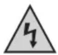
The triangle containing a lightning symbol warns against danger of electric shock or impairment of the electrical safety of the device.

An exclamation mark in a triangle indicates important notes in these operating instructions that must be strictly observed.

The „hand“ symbol indicates special information and advice on operation.
5. Operating elements
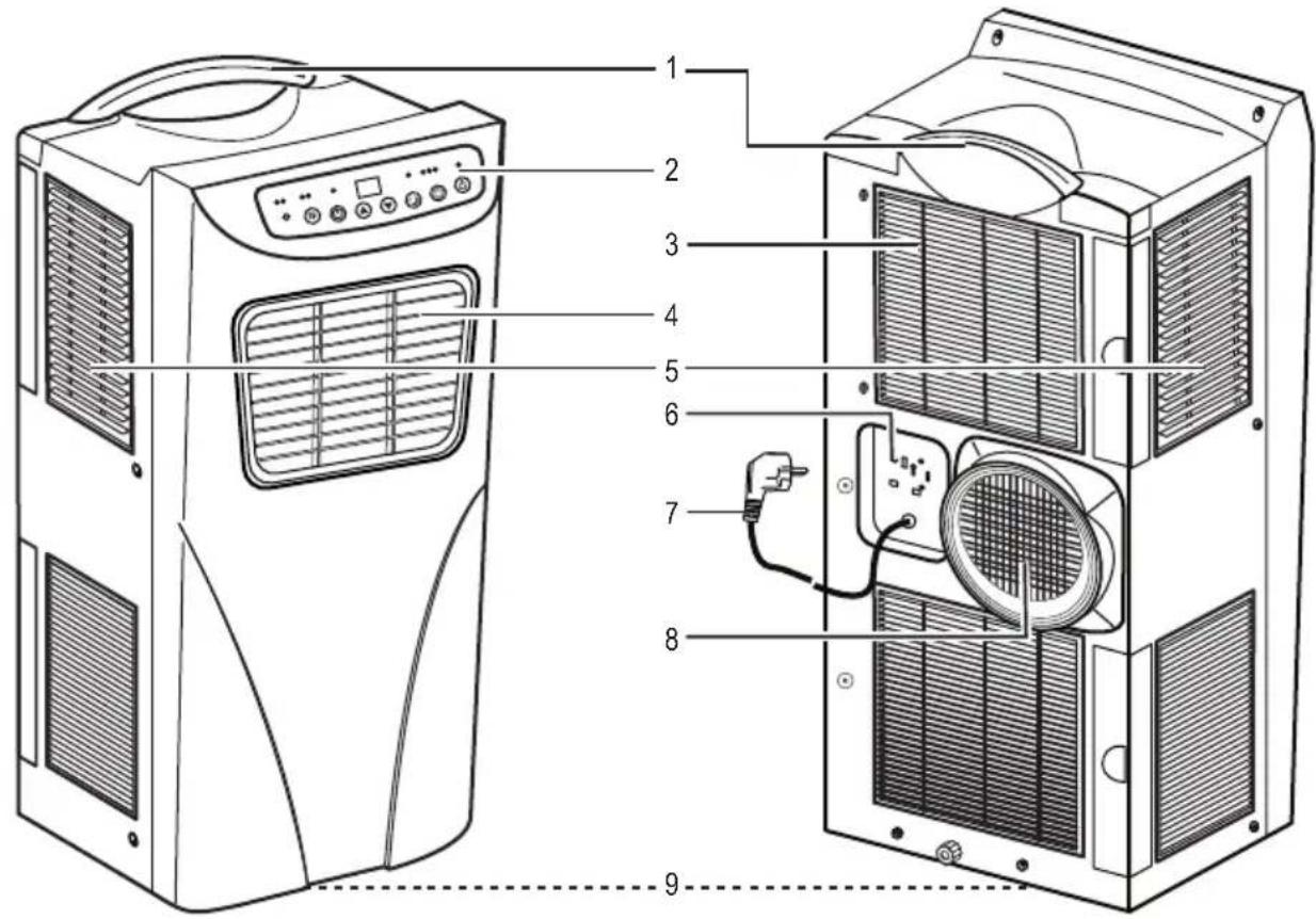
a) Mobile air-conditioning unit
text_image
Technical diagram of a dual-chamber air conditioner unit with numbered components for identification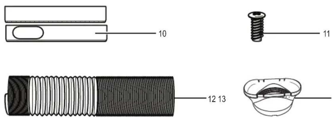
text_image
10 11 12 13b) Operating panel
text_image
14 15 16 17 18 19 20 21 22 23 24 WF COMP HIGH LOW TIMER SLEEP COOL DEHUM FAN POWER 2526272829303132c) Remote control

text_image
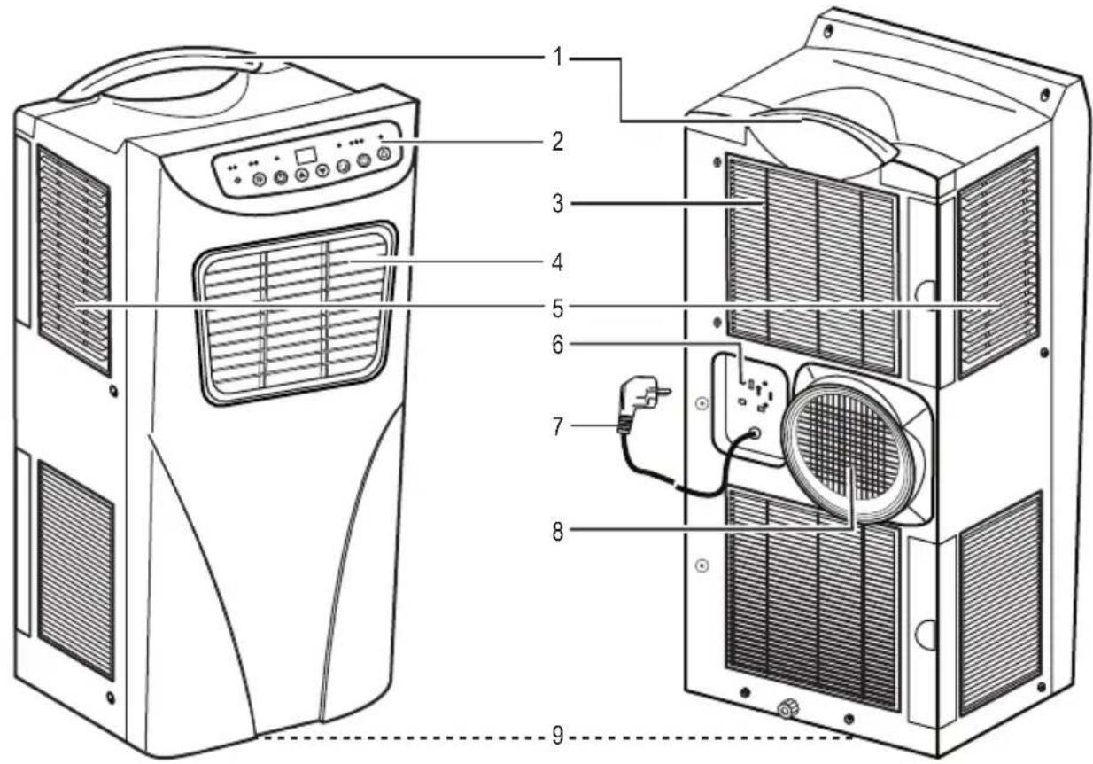
41 40 39 38 33 34 35 36 371 Handle
2 Operating panel
3 Rear air filter
4 Air exhaust openings (adjustable verticality/horizontally)
5 Side air filter
6 Power plug storage
7 Power cord with power plug
8 Exhaust opening
9 Wheels (not shown)
10 Extendable window guide (inner/outer part)
11 6 x crosshead screws
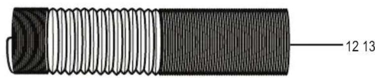
12 Flexile exhaust hose
13 Adapter (for exhaust hose)
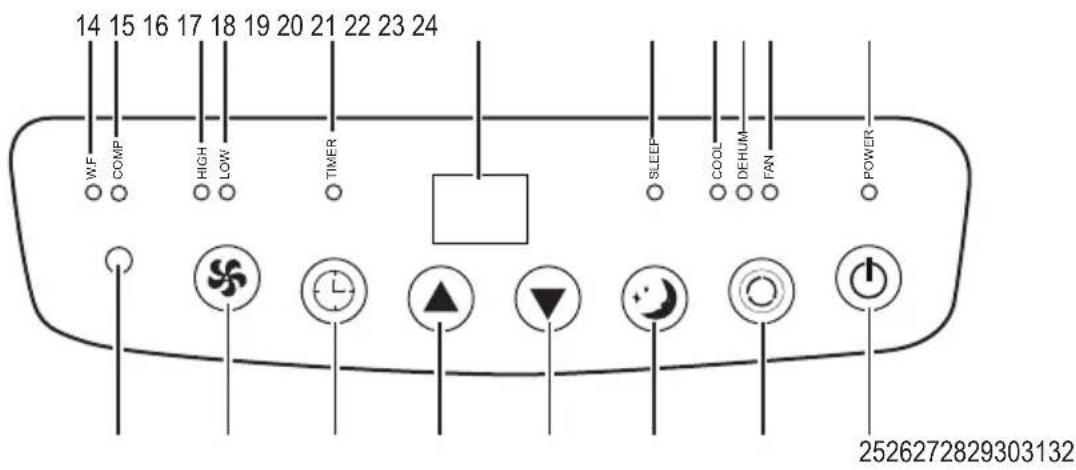
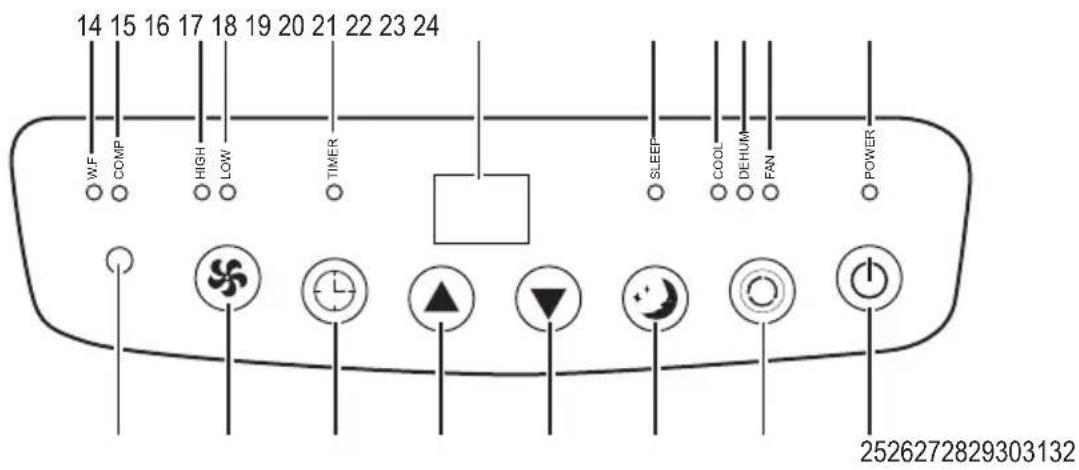
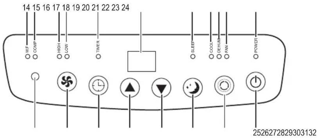
14 Indicator light W.F (water tank full)
15 Indicator light COMP
16 Indicator light HIGH
17 Indicator light LOW
18 Indicator light TIMER
19 Display
20. Indicator light SLEEP
21. Indicator light COOL
22 Indicator light DEHUM
23 Indicator light FAN
24 Indicator light POWER
25 ⏻ Key (on/off switch)
26 Key (select operating mode)
27 ⚙️ Key (sleep mode)
28 ▼ Key (reduce value)
29 Key (increase value)
30 Ⓤ Key (timer)
31 ⚙️ Key (fan speed)
32 IR receiver
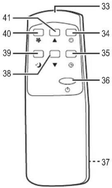
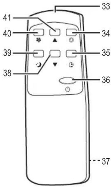
33 IR sender
34 ☐ Key (select operating mode)
35 ⏻Key (timer)
36 ⏻ Key (on/off switch)
37 battery compartment (rear)
38 ▼ Key (reduce value)
39 Key (sleep mode)
40 ✦ Key (fan speed)
41 ▲Key (increase value)
6. Safety information


Read the operating instructions carefully and especially observe the safety information. If you do not follow the safety instructions and information on proper handling in this manual, we assume no liability for any resulting personal injury or damage to property. Such cases will invalidate the warranty/guarantee.
a) People / Product
- The device is not a toy. Keep it out of the reach of children and pets.
- Do not leave packaging material lying around carelessly. These may become dangerous playing material for children.
- Protect the product from extreme temperatures, direct sunlight, strong jolts, high humidity, moisture, flammable gases, vapours and solvents.
- Do not place the product under any mechanical stress.
-
If it is no longer possible to operate the product safely, take it out of operation and protect it from any accidental use. Safe operation can no longer be guaranteed if the product:
-
is visibly damaged,
- is no longer working properly,
- has been stored for extended periods in poor ambient conditions or
- has been subjected to any serious transport-related stresses.
- Please handle the product carefully. Jolts, impacts or a fall even from a low height can damage the product.
- The mains outlet must be located near to the device and be easily accessible.
- Never pull the mains plug from the socket by pulling at the cable. Always pull it from the mains socket using the intended grips.
- Unplug the mains plug from the mains socket if you do not use the device for an extended period of time.
- Disconnect the mains plug from the mains socket in thunderstorms for reasons of safety.
- Make sure that the mains cable is not squeezed, bent, damaged by sharp edges or put under mechanical stress. Avoid excessive thermal stress on the mains cable from extreme heat or cold. Do not modify the mains cable. Otherwise the mains cable may be damaged. A damaged mains cable can cause a deadly electric shock.
- Do not touch the mains cable if it is damaged. First, power down the respective mains socket (e.g. via the respective circuit breaker) and then carefully pull the mains plug from the mains socket. Never use the product if the mains cable is damaged.
- A damaged mains cable may only be replaced by the manufacturer, a workshop commissioned by the manufacturer or a similarly qualified person, so as to prevent any danger.
- Never plug in or unplug the mains plug when your hands are wet.
- Disconnect the power plug from the power outlet to completely disconnect the device from the power network. Never disconnect the plug while the device is still switched on. Always use the keys on the remote control or the operating panel to switch the device on and off.
- Disconnect the power plug from the power outlet for maintenance or to move the device.
- Ensure that the mains voltage corresponds to the data listed on the data plate of the device. Connect the device only to an isolated ground receptacle.
- Do not open the device. Do not insert any objects in to the openings.
- Do not cover the device. Ensure sufficient ventilation. Keep a space of at least 50 cm in all directions around the device in order to ensure sufficient ventilation.
- Always transport and place of the device in an upright position. Never used the device in a sloping position.
- Do not sit on the device and do not place any objects on the device.
- Do not operate the device with damp hands or while standing on wet ground.
- Do not move the device while it is in operation.
- Avoid contact of the device with chemicals.
- Do not use spray cans near the device.
- Do not use device near gases or flammable substances like alcohol, insecticides, gasoline, etc.
- Warning - risk of electric shock! Never attempt to repair the device yourself. In case of malfunction, always have it repaired by qualified professionals.
- This device is not intended to be used by persons (including children) with reduced physical, sensory or mental abilities or lack of experience and / or lack of knowledge unless they are supervised by a person responsible for their safety or have received instructions on how to use the device.
- Children should be supervised to ensure that they do not play with the device.
- Do not use the device if it fell to the ground or damages are visible.
- Use the device only at a room temperature of 15 °C to 43 °C. The product will be damaged at a room temperature of more than 43 °C.
b) Batteries / Rechargeable batteries
- Correct polarity must be observed while inserting the (rechargeable) batteries.
- (Rechargeable) batteries should be removed from the device if it is not used for a long period of time to avoid damage through leaking. Leaking or damaged (rechargeable) batteries might cause acid burns when in contact with skin, therefore use suitable protective gloves to handle corrupted (rechargeable) batteries.
- (Rechargeable) batteries must be kept out of reach of children. Do not leave (rechargeable) batteries lying around, as there is risk, that children or pets swallow them.
- All (rechargeable) batteries should be replaced at the same time. Mixing old and new (rechargeable) batteries in the device can lead to (rechargeable) battery leakage and device damage.
- (Rechargeable) batteries must not be dismantled, short-circuited or thrown into fire. Never recharge non-rechargeable batteries. There is a risk of explosion!
c) Miscellaneous
- Consult an expert when in doubt about operation, safety or connection of the device.
- Maintenance, modifications and repairs are to be performed exclusively by an expert or at a qualified shop.
- If you have questions which remain unanswered by these operating instructions, contact our technical support service or other technical personnel.
7. Start-up operation
a) Unpacking and inspection
Attention! The product is heavy. We therefore recommend that two people remove the packaging of the product.
- Set packaging aside carefully.
- Open the bottom of the packaging and fold the bottom flaps toward the outside.
- Put the product into a vertical position and remove the packaging by putting it up.
- Let the product stand in a vertical position for at least two hours prior to switching the product on.
- Inspected the content of the packaging for completeness and damages. If the content of the packaging is incomplete or if damages are found, do not operate the product. Return it to your seller immediately.
- Comply with statutory provisions to dispose of the packaging material.
- Store the packaging material if you would like to use it to package, ship, or transport the device in any way. Store it in such a way that it does not pose a potential risk.
b) Assembly
natural_image
Diagram showing a cylindrical object with internal components and directional arrows indicating rotation or movement (no text or symbols)
natural_image
Technical illustration of a mechanical device with internal components and directional arrows indicating motion (no text or symbols)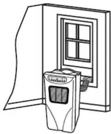
natural_image
Line drawing of a door with an air conditioner unit and window, no text or symbols presentDia. A Dia. B Dia. C
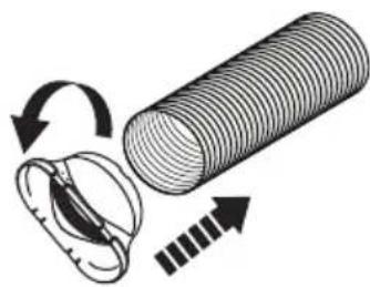
- First pull apart the exhaust hose (12) on one side. Attach the adapter (13) on the exhaust hose by twisting it onto the exhaust hose counter clockwise (Dia. A). The exhaust hose can be pulled out and bent into the desired shape.
- Then attach the exhaust hose (12) with the adapter onto the exhaust opening (8) by twisting it counter clockwise (Dia. B).
- Place the device near a window or a door. Carefully pull out the exhaust hose (12), if required. We recommend keeping the length of the hose as short as possible.
- Open the window and measure the width of the window. The window guide (10) can be used only with sliding windows.
- If the window is too wide for the window guide (10), you can obtain an additional window guide from your seller. Obtain information from your seller.
- If the window is too narrow for the window guide (10), remove the inner part of the window guide.
- Shorten the inner part of the window guide (10) to the desired length.
-
Insert this into the outer part of the window guide (10) and extend the window guide to the required length on the window.
-
Drilled holes are located on the inside of the inner part. Use the enclosed crosshead screws to attach it to the window.
- The window guide (10) will be fastened when the window is closed.
- Now guide the adapter (13) into the opening of the window guide (10) (Dia. C).
You can also hang the exhaust hose (12) out of the window without using the window guide (10). Close the window as much as possible to prevent warm air from flowing back in.
natural_image
Technical line drawing of a mechanical device with a curved pipe and mounting bracket (no text or symbols)Dia. D Dia. E
natural_image
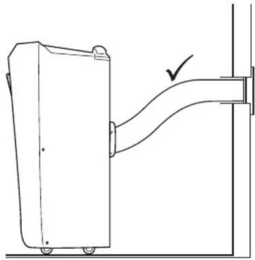
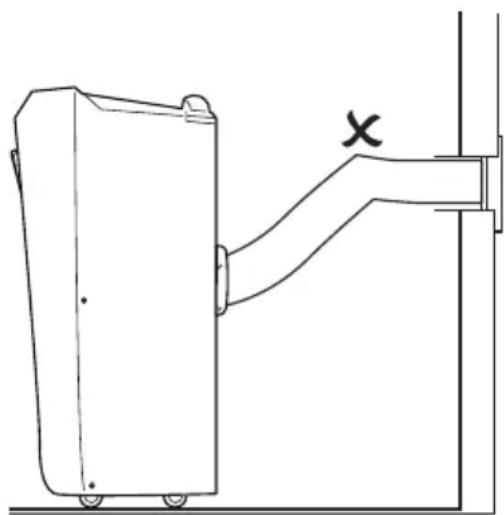
Technical line drawing of a mechanical device with a bracket and mounting bracket (no text or symbols)- During the installation, the exhaust hose (12) should be placed as straight as possible (Dia. D). Do not extent it and do not connect it to other exhaust hoses, which may cause malfunction.
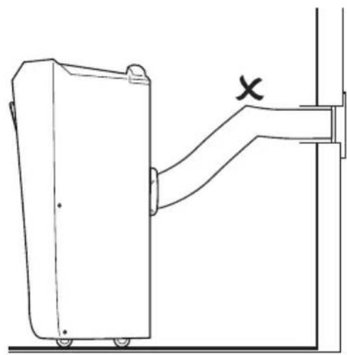
- Do not bend the exhaust hose (12) (Dia. E).

Attention! Place the product in an upright position and wait for approximately 2 hours prior to switching the device on, so that the coolant can flow into the necessary lines.
c) Remote control
The remote control is operated with 2 x 1.5 V batteries type R03/LR03/AAA (not included).
- Open the battery compartment (37) on the rear of the remote control. Insert the batteries according to the correct polarity (+/-).
- Use only batteries of the same or similar type.
- Remove all batteries if the device is not used for a longer period of time in order to prevent damages.
- Then close the battery compartment. Ensure that the lid is correctly fastened.
- Comply with the safety information regarding the handling of batteries/rechargeable batteries (see section "b) Batteries/Rechargeable batteries").
• Always point the IR sender (33) toward the IR receiver (32) on the operating panel (2) when using the remote control. - Ensure that there are no obstructions located between the remote control and the device, e.g. furniture, which might block transmission of the signal.
8. Operation
Settings can be adjusted directly on the operating panel (2) of the device or the enclosed remote control.
Always place the device on a level, sturdy, and dry surface. Ensure a sturdy position, so that the device cannot tip over or fall down.
When you connect to the power plug (7) to the power outlet, a signal tone sounds, the indicator light POWER (24) and the display (19) will light up. The device is now in standby mode
a) Switching on and off
- Push the key (25, 36) to switch the device on or off.
- The device is pre-set. When you switch the device on, the display (19) will show the temperature 22 °C, the indicator lights COOL (21) and LOW (17) will light up. Low fan speed is pre-set. When the compressor switches on, the indicator light COMP (15) will light up.
- The compressor will switch on approximately 3 minutes after the device has been switched on.
- Once you switch the device off, wait approximately 3 minutes before switching the device back on.
- Use the air exhaust openings (4) to adjust the direction of the airflow.
- Push the key Ⓞ (26, 34) to select between the operating modes “Cooling” (COOL), “Dehumidify” (DEHUM) and “Fan” (FAN).
b) Cooling (COOL)
- Select the operating mode "Cooling". The indicator light COOL (21) will light up.
- Push the keys (29, 41) or (28, 38) to adjust the temperature from 16^ to 31^ .
- Push the key ⚙(31, 40) to set a high or low fan speed. With high fan speed, the indicator light HIGH (16) will light up. With low fan speed, the indicator light LOW (17) will light up.
The cooling function shuts off automatically if the room temperature is lower than the set temperature. The indicator light COMP (15) will go out. Once the room temperature increases, the cooling function switches on automatically.
c) Dehumidify (DEHUM)
- Select the operating mode "Dehumidify". The indicator light DEHUM (22) will light up.
- The temperature, the sleep mode, and the fan speed (HIGH/LOW) cannot be set.
Keep doors and windows closed to achieve a better dehumidification performance.
d) Fan (FAN)
- Select the operating mode "Cooling". The indicator light FAN (23) will light up.
- Push the key ⓕ(31, 40) to select a high or low fan speed. With a high fan speed, the indicator light HIGH (16) will light up. With a low fan speed, the indicator light LOW (17) will light up.
• Temperature and sleep mode cannot be set.
e) Timer (TIMER)
Automatic on
- You can specify the time until the device switches on automatically from standby mode.
- Push the key (30, 35) to select the desired time period (1 – 24 hours).
- The indicator light TIMER (18) lights up and "01" (=1 hour) will flash on the display.
- Push the key (30, 35) repeatedly to select the desired time period. For example, if you would like to set three hours, push the key (30, 35) three times. "03" will flash on the display.
- Once the hour display stops flashing your settings are confirmed.
- To switch the timer off, push the key ⏻(30, 35) repeatedly, until "00" flashes on the display. The indicator light TIMER (18) will go out.
- The device switches on automatically after the pre-set time has elapsed.
Automatic off
- When the device is switched on, you can specify the time until the device switches off automatically.
- Push the key (30, 35) to select the desired time period (1 – 24 hours).
- The indicator light TIMER (18) lights up and "01" (=1 hour) will flash on the display.
- Push the key ⓞ (30, 35) repeatedly to select the desired time period. For example, if you would like to set three hours, push the key ⓞ (30, 35) three times. "03" will flash on the display.
- Once the hour display stops flashing your settings are confirmed.
- To switch the timer off, push the key Ⓤ (30, 35) repeatedly, until "00" flashes on the display. The indicator light TIMER (18) will go out.
- The device switches off automatically after the pre-set time has elapsed.
f) Sleep mode (SLEEP)
- Select the operating mode "Cooling". The sleep mode is possible only in the operating mode "Cooling".
- Push the key (27, 39) to enter sleep mode. The fan speed is set on low.
- Once you selected the sleep mode, the temperature will increase by 1 °C after one hour. After another hour, the temperature will again increase by 1 °C and will then remain constant.
• The sleep mode is not possible,
- if the water tank is full (indicator light W.F = "Water Full" will light up).
- if the devices in standby mode.
9. Troubleshooting
With this air conditioning unit you have purchased a state-of-the-art, reliable device. However, problems and malfunctions may occur; we would therefore like to inform you of how you can resolve possible malfunctions.
The device does not work.
- The device is not connected to the power network. Connect the power plug to a suitable power outlet.
- The safety fuse of the respective power outlet has blown.
- If required, inspect the function of the power outlet using another device.
The remote control does not work.
- Inspect whether batteries are located in the remote control and whether these are inserted according to the right polarity
- The remote control is outside of the range of the device. Change the distance of the remote control to the device.
- The batteries of the remote control are empty. Insert new batteries.
The device does not cool.
- Ensure that windows and doors are closed. Warm air can enter the room.
- The filters are soiled. Follow instructions in chapter "10. Maintenance and cleaning".
- The air exhaust openings are blocked. Ensure that the air exhaust openings are not blocked. Ensure an open space of at least 50 cm in all directions around the device for sufficient ventilation.
10. Maintenance and cleaning

Switch to device off and disconnect the power plug (7) from the power outlet prior to cleaning the device. Let the device cool off completely.
Insert the power plug into the power plug storage (6) protected from damage.
a) Casing
- Wipe the casing with a slightly damp cloth.
- Ensure that no liquid enters the inside of the casing.
- Do not use abrasive or solvent-based cleaners as well as abrasive or pointy objects.
- Never hold the device under flowing water white cleaning it, and do not submerge it in water or other liquids.
b) Cleaning air filters
- Clean the air filters (3, 5) periodically.
- First pull out the rear air filters (3) located on the rear.
- Then pull out the site air filters (5).
- Use a vacuum cleaner to clean the air filters (3, 5). If the filters are heavily soiled, wash them with warm water and a mild cleaning agent. Let them dry completely before reinserting them.
- Then correctly reinsert the air filters. Be sure to first insert of the site air filters. Then insert the rear air filter (3).

Attention! Never use the device without air filters.
c) Emptying water container
- Empty the inner water container when it is completely full. The indicator light W.F (14) will flash and a signal will sound. The device cannot be operated.
- Disconnect the power plug from the power outlet.
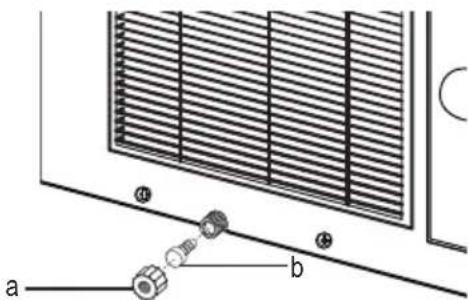
- Place a suitable container under the drainage opening. Twist the fastener (a) off and pull the plug (b) from the drainage opening (Dia. F).
- Let the water drain. When the container is almost full, close the drainage opening again using the plug; empty the container and repeat the process until water stops dripping.
- Reinsert the plug (b) into the drainage opening and twist the fastener (a) back on.
- When you switch the device on, the indicator light W.F (14) no longer lights up.
- Do not leave the device unsupervised while emptying the water container. The container may overflow.
- If the device will not be used for a long period of time, use the key ⏻ (25, 36) to switch it on prior to storing it, and let it run in ventilation mode for several hours on a warm, dry day. This will help dry the interior of the device completely. We also recommend leaving the device standing for one day without fastener and plug, to air dry it.
text_image
Technical diagram showing a panel with heat exchanger and two labeled components (a and b) connected by a spring-like tool.Dia. F
d) Storage
Store the device in a cool, dry, clean location protected from sun exposure, and in the original packaging if possible.
11. Disposal
a) Product
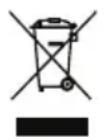
Electrical and electronic products do not belong in the household waste.
Dispose of the product according to the applicable statutory provisions at the end of its service life.
Remove any inserted (rechargeable) batteries and dispose of them separately from the product.
b) (Rechargeable) Batteries
As the end user, you are required by law (Battery Ordinance) to return all used (rechargeable) batteries; disposal of them in the household waste is prohibited!
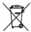
Contaminated (rechargeable) batteries are labelled with this symbol to indicate that disposal in the domestic waste is forbidden. The designations for the heavy metals involved are: Cd = Cadmium, Hg = Mercury, Pb = Lead (name on (rechargeable) batteries, e.g. below the trash icon on the left).
Used (rechargeable) batteries can be returned to collection points in your municipality, our stores or wherever (rechargeable) batteries are sold.
You thus fulfil the legal requirements and make your contribution to protecting the environment.
12. Technical specifications
a) Air-conditioning unit (item no. 396453)
Model number......JHS-A001-08KR/B1
Operating voltage 220 - 240 V/AC, 50 Hz
Power consumption....890 W
Cooling capacity. 8000 BTU/h (2.4 kW)
Air throughput....380 m ^4 /h
Coolant/volume....R410A/370 g
Adjustable temperature range ....16 – 31 °C
Noise level....64 dB(A)
Suitable for 8 - 12 m ^2
Exhaust hose length....1.5 m
Fuse....FSD or 50F, F.3.15AL, 250 V/AC
Dimensions (W x H x D) 320 x 730 x 360 mm
Weight .....approx. 21 kg
b) Air-conditioning unit (item no. 396454)
Model number......JHS-A001-10KR/B1
Operating voltage 220 - 240 V/AC, 50 Hz
Power consumption....1100 W
Cooling capacity. 10000 BTU/h (2.9 kW)
Air throughput....400 m ^3 /h
Coolant/volume....R410A/460 g
Adjustable temperature range ....16 – 31 °C
Noise level....65 dB(A)
Suitable for 12 - 18 m ^2
Exhaust hose length....1.5 m
Fuse.....FSD or 50F, F.3.15AL, 250 V/AC
Dimensions (W x H x D) 320 x 730 x 360 mm
Weight .....approx. 24 kg
c) Remote control
Power supply....2 x 1.5 V/DC batteries (R03/LR03/AAA)
Dimensions (W x H x D) 165 x 38 x 15 mm
Weight 65 g
Table des matières
F
text_image
Technical diagram of a dual-chamber air conditioner unit with numbered labels pointing to internal components.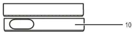
natural_image
Simple line drawing of two rectangular blocks with a central oval and a horizontal line labeled '10' (no text or symbols beyond the number)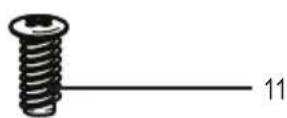

text_image
12 13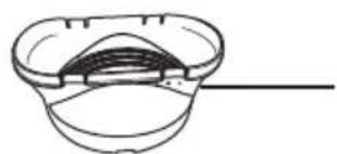
natural_image
Simple line drawing of a bowl with a side panel and a horizontal line extending from the center (no text or symbols)natural_image
Diagram of a cylindrical object with internal components and directional arrows indicating rotation or movement (no text or symbols)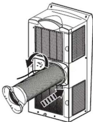
natural_image
Technical illustration of a mechanical device with internal components and directional arrows indicating motion (no text or symbols)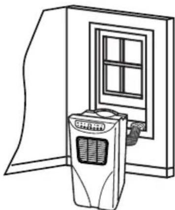
natural_image
Line drawing of a portable air conditioner unit inside a cabinet (no text or symbols)Fig. A Fig. B Fig. C
natural_image
Technical line drawing of a mechanical device with a curved pipe and a checkmark indicating a detail (no text or symbols present)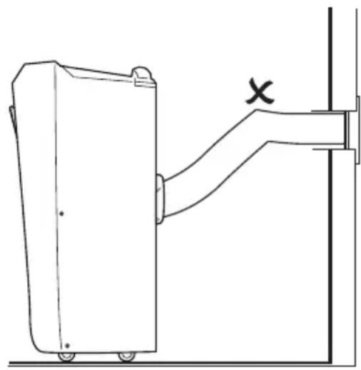
natural_image
Technical line drawing of a mechanical device with a bracket and labeled X (no text or symbols beyond the label)Fig. D Fig. E
Dimensions (L x H x P)....320 x 730 x 360 mm
Poids....env. 24 kg
c) Télécommande
Dimensions (L x H x P)....165 x 38 x 15 mm
Poids....65 g
a) Mobile airconditioning
text_image
Technical diagram of a dual-chamber air conditioner unit with numbered components for identification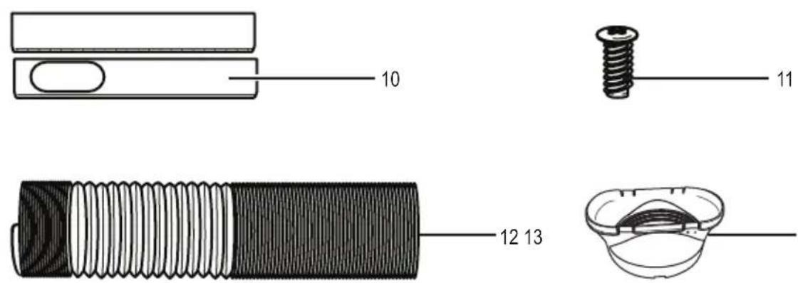
text_image
10 11 12 13b) Bedieningspaneel
text_image
14 15 16 17 18 19 20 21 22 23 24 WF COMP HIGH LOW TIMER SLEEP COOL DEHUM FAN POWER 2526272829303132c) Afstandsbediening
text_image
41 40 39 38 33 34 35 36 37natural_image
Diagram of a cylindrical object with internal components and directional arrows indicating rotation or movement (no text or symbols)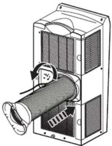
natural_image
Technical illustration of a mechanical device with internal components and directional arrows indicating motion (no text or symbols)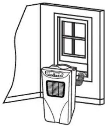
natural_image
Line drawing of a portable air conditioner unit with a window and door, no text or symbols presentnatural_image
Technical line drawing of a door handle assembly with a checkmark indicating a detail (no text or symbols present)Afb. D Afb. E
natural_image
Technical line drawing of a mechanical device with a bracket and mounting bracket (no text or symbols)text_image
Technical diagram showing a panel with labeled components a and b, likely illustrating a mechanical or electrical assembly.Afb. F
d) Opslag
Zekering....FSD of 50F, F.3.15AL, 250 V/AC
Afmetingen (B x H x D)....320 x 730 x 360 mm
Zekering....FSD of 50F, F.3.15AL, 250 V/AC
Afmetingen (B x H x D)....320 x 730 x 360 mm
© Copyright 2013 by Conrad Electronic SE.

Legal Notice
These operating instructions are a publication by Conrad Electronic SE, Klaus-Conrad-Str. 1, D-92240 Hirschau (www.conrad.com).
All rights including translation reserved. Reproduction by any method, e.g. photocopy, microfilming, or the capture in electronic data processing systems require the prior written approval by the editor. Reprinting, also in part, is prohibited.
These operating instructions represent the technical status at the time of printing. Changes in technology and equipment reserved.
© Copyright 2013 by Conrad Electronic SE.