USER MANUAL PAC FX140 ECO DELONGHI
Thank you for having purchased an appliance made by De' Longhi, the international leader in portable air conditioning units. Thanks to our years of experience all around the world we are constantly improving the quality and performance of Pinguino. We are confident that you will be satisfied with your purchase and enjoy the cool comfort created by the Pinguino for many years to come. You should spend some time reading this instruction manual and keep it handy to refer to in order to use your Pinguino in conditions of maximum efficiency and peace of mind.
Chère Cliente, Cher Client.
B
PROBLEMI CAUSE RIMEDI
What is Pinguino Pinguino and SuperPinguino
During the summer, optimum comfort is achieved with a temperature of between 24 and 27°C and about 50% relative humidity.
An air conditioner removes moisture and heat from the room where it is located. One advantage of portable air conditioning units over fitted models is that they can be moved from one room to another in the home or even transferred between different buildings.
The hot air in your room is passed through a coil cooled by refrigerant gas, losing excess heat and moisture before being discharged again into the room. In single unit models (Pinguino), a small part of this air is used to cool the refrigerant gas before, hot and moist, being discharged outside.
In suitcase models (Super-Pinguino), the circuit is cooled using the air outside.
Each Pinguino and Super-Pinguino can also be used as a fan only.
ECO by Pinguino is the late-
st generation of ecological
air conditioners. Pinguino
does not contain gases dan-
gerous to the earth's ozone
layer (CFC/HCFC). In addition,
thanks to the extreme efficiency of
the appliance, not only does it save
you money on your electric bills, but it
saves the environment by not negatively contri-
buting to the greenhouse effect."
For more details, contact or visit our Internet site www.delonghi.it
Important Safe-guards
- This appliance has been manufactured to cool and de-humidify domestic environments and should not be used for other purposes.
- It is dangerous to alter or modify the unit's characteristics in any way.
- The appliance must be installed in conformity with the relevant national legislation.
- Should repairs be necessary, contact the nearest authorised Repair Service Centre. Unauthorised servicing can be dangerous.
- In the case that the power cable becomes damaged, this must be substituted only by specialised personnel authorised by the manufacturer.
- This appliance is to be used by adults only; keep children away from it.
• Always ground the appliance. Have the electrical system checked by a qualified electrician.
• A void using extension leads with the unit.
- Before cleaning or maintenance operations, always unplug the unit from the socket.
- Do not pull on or place strain on the power cable when moving the appliance.
- The appliance should not be installed where the atmosphere may contain combustible gases, oil or sulphur, or near heat sources.
- This appliance must be utilised and installed only in rooms with a total volume of 15 cubic metres or greater.
• After turning off the conditioner, always wait at least three minutes before turning it on again.
- Do not rest hot or heavy objects onto the appliance.
- Clean the filters at least once a week.
• A void using heaters near the unit.
- If it is not possible to transport the appliance in an upright position, then either lay it on its side. Before transporting the unit drain the condensation collecting-tray and tank. After transportation, wait at least 1 hour before switching on the unit.
- The packaging materials can be recycled. You are therefore recommended to place them in the special containers for differentiated waste collection.
Setting up
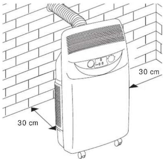
The following instructions will help you set up your air conditioning unit as efficiently as possible. The appliance must always be installed for use taking care that there are no obstacles blocking the ventilation and exhaust fans.
AIR CONDITIONING WITHOUT INSTALLATION
With just a few simple operations, Pinguino will restore comfortable conditions in your room:
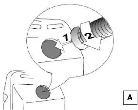
- Fix the air outlet tube to the coupling
5 on the back of the unit as shown in figure A.
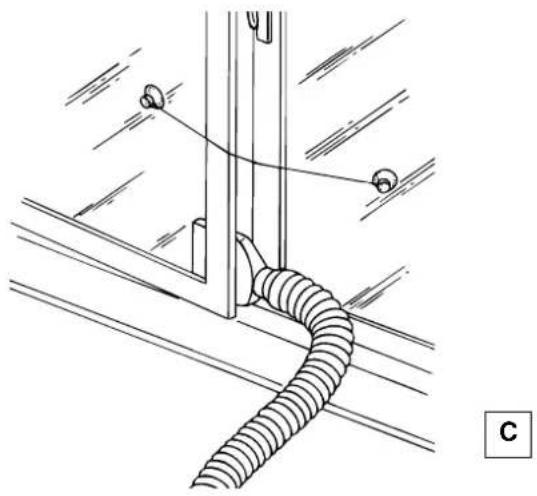
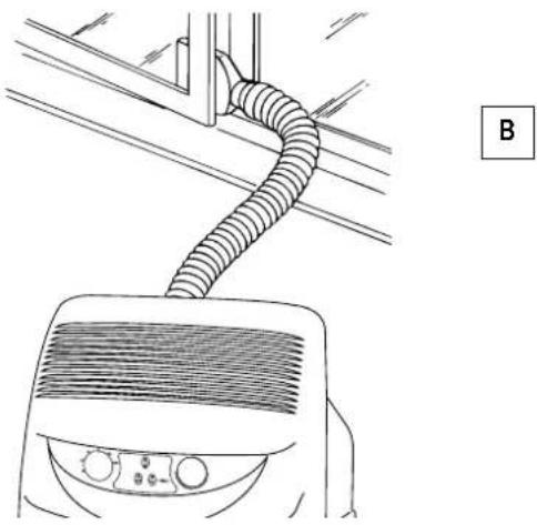
- With a double casement window, use the suckers provided to hold the two halves of the window together (fig. C).
- Fix the window attachment to the end of the tube .18
- Place the unit near a window or a French window.
- Open the window or French window slightly and place the window attachment 18 as shown in figure B.
Setting up
AIR CONDITIONING WITH INSTALLATION
Pinguino can also be semi-permanently installed
To install, proceed as follows:
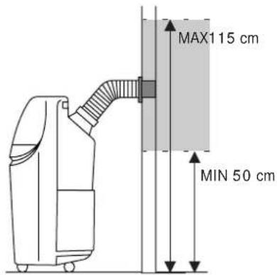
- Make a hole in a wall communicating with the outside or through the pane of a window. Respect the height and dimensions given in figure D
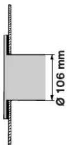
in a window pane
in the
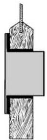
wood sill of
a window
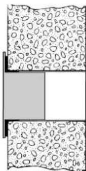
in the wall: for optimum results, insulate the section of the wall with suitable insulating material.

- Fit the flange supplied to the hole.
- Fix the tube to the coupling on the back of the unit (figure A).
- Attach the end of the tube to the flange 16 shown in the figure E.
E
When the tube 17 not attached, close the hole with the bung on the flange .16
NOTE:
When the unit is installed semi-permanently, we recommend leaving a door slightly open (1 cm is enough) to ensure an adequate exchange of air.
DEHUMIDIFICATION
Position the appliance in the room without inserting the tube; in this way the dehumidified air will exhaust directly into the room.
Turning on and Selecting functions
ELECTRICAL CONNECTION
Before plugging in check that:
- the mains supply corresponds to the value shown in the specifications table;
- the socket and the mains lead correspond to the power requirements of the appliance;
- the socket is suited to the plug 10 otherwise have the socket replaced;
- the socket is properly grounded. The manufactures cannot be held responsible for any damages due to failure in following normal safety procedures.
Replacement of the power cable must be carried out by qualified personnel.
AS AIR CONDITIONER
With the unit turned off, the function selector is in the "O" position. To turn the unit on in air conditioning mode, proceed as follows:
- Rotate the function selector knob clockwise:
- Place the large crystal symbol in line with the reference mark to operate the unit in air conditioning mode at maximum fan speed.
- Place the small crystal symbol × in line with the reference mark to operate the unit in air conditioning mode at minimum fan speed.
- Now set the required temperature by rotating the room thermostat knob.
Note
The temperature is not expressed in degrees. We therefore recommend rotating the room thermostat knob to the maximum cool position. When room temperature has reached the required level, rotate the thermostat knob SLOWLY clockwise until the thermostat is activated, turning the unit off. This programs the unit to the precise level of comfort required which will then be automatically maintained by the thermostat with considerable energy savings. When regulating the thermostat, the air conditioning function is temporarily interrupted and the unit continues to operate in fan only mode.
THIS UNIT EMPLOYS AN EXCLUSIVE CONDENSATION RECYCLING SYSTEM TO DISPOSE OF EXCESS MOISTURE.
IN NORMAL CONDITIONS, CONDENSATION IS DISPOSED OF AUTOMATICALLY. WHEN THE HUMIDITY IS PARTICULARLY HIGH, AN EXCESS OF CONDENSATION MAY BUILT UP IN THE TANK. WHEN THIS HAPPENS, THE INDICATOR LIGHT ⚙ 12 COMES ON INDICATING THAT THE TANK SHOULD BE EMPTIED. MAKE SURE THE TANK IS PUT BACK CORRECTLY OTHERWISE THE LIGHT WALL REMAIN ON.
AIR PURIFICATION WITH FAN
Your air conditioning unit has two special high efficiency electrostatic 3M FILTRETETM filters. These filters, active in all modes, filter out extremely fine particles (down to 0.3 thousands of a millimetre).
If you want to purify the air by ventilating the room only, rotate the function selector 13 anticlockwise.
- Place the large symbol in line with the reference mark to operate the unit in air purification mode at maximum fan speed.
- Place the small symbol ≈ in line with the reference mark to operate the unit in air purification mode at minimum fan speed.
HOW TO DEHUMIDIFY
When the appliance is working as an air conditioner, it automatically reduces the excess humidity in the air present in the room. This is eliminated through the exhaust tube .9
If only the elimination of the excess humidity in the room is desired without lowering the temperature, simply turn the function selector knob in a counterclockwise direction until the symbol is reached.
Note
In the dehumidifying mode, air colder than the room temperature will exhaust from the air exhaust grill. Conversely, air warmer than room temperature will be exhausted from the accommodation tube 5n the back side of the appliance.
Functions/Warning lights
TURN THE APPLIANCE OFF
TO TURN THE UNIT OFF COMPLETELY, SET THE FUNCTION SELECTOR TO THE "O" POSITION AND UNPLUG FROM THE MAINS
THE START OF THE FUNCTIONS MAY UNDERGO SLIGHT DELAYS WITH RESPECT TO THE ROTATION OF THE SELECTOR.
THE LEDS
Led displays come on depending on the selected function or as warning of possible anomalies.
| FUNCTION | LED ⬆ / ✘12 | LED ≈13 |
| OFF | - | - |
| AIR-CONDITIONING | on* on | |
| DEHUMIDIFYING | on** on | |
| PURIFYING | -on | |
* The leds will light up 3 minutes after the machine is turned on (that is, when the compressor starts to work). They will turn off when the temperature set by the thermostat is reached.
** The leds will light up 3 minutes after the machine is turned on (that is, when the compressor starts to work)
When in the dehumidifying mode, the appliance operates continuously. If the temperature is too low, the anti-freeze thermostat intervenes, interrupting the operation.
ELECTRICAL CONNECTION (U.K. ONLY)
A) If your appliance comes fitted with a plug, it will incorporate a 13 Amp fuse. If it does not fit your socket, the plug should be cut off from the mains lead, and on appropriate plug fitted, as below. warning: Very carefully dispose of the cut off plug after removing the fuse: do not insert in a 13 Amp socket elsewhere in the house as this could cause a shock hazard. With alternative plugs not incorporating a fuse, the circuit must be protected by a 15 Amp fuse. If the plug is a moulded-on type, the fuse cover must be re-fitted when changing the fuse using a 13 Amp Asta approved fuse to BS 1362. In the event of losing the fuse cover, the plug must NOT be used until a replacement fuse cover can be obtained from your nearest electrical dealer. The colour of the correct replacement fuse cover is that as marked on the base of the plug.
B) If your appliance is not fitted with a plug, please follow the instructins provided below:
WARNING - THIS APPLIANCE MUST BE EARTHED
IMPORTANT
The wires in the mains lead are coloured in accordance with the following code:
Green and yellow Earth
Blue Neutral
Brown Live
As the colours of the wires in the mains lead may not correspond with the coloured markings identifying the terminals in your plug, proceed as follows:
The green and yellow wire must be connected to the terminal in the plug marked with the letter E or the earth symbol
or coloured green or green and yellow.
The blue wire must be connected to the terminal marked with the letter N or coloured black.
The brown wire must be connected to the terminal marked with the letter L or coloured red.
Recommendations
Follow these recommendations to achieve maximum efficiency from your air conditioning unit:
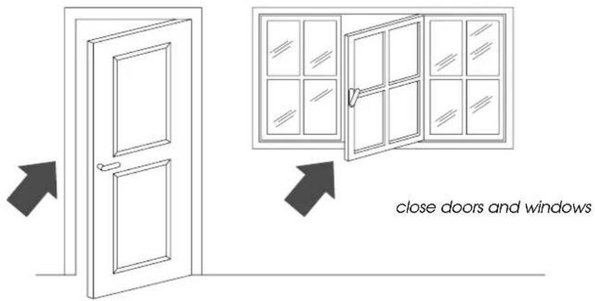
- C lose the doors and windows in the room where the unit is functioning. The only exception is in the case of installation through a hole in the wall. In this case, you are recommended to allow a small amount of air to enter through a door or window to guarantee an adequate exchange of air.
- Do not use the appliance outdoors.
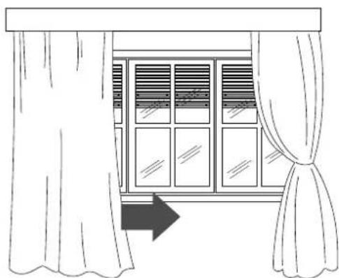
- P rotec the room from direct exposure to the sun's rays by drawing the curtains and/or partially lowering the blinds so as to maximise energy savings.
- Do not rest objects on the air conditioning unit.
- Do not obstruct the air intake or outlet 1.
- Make sure there are no heat sources in the room.
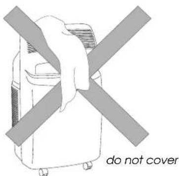

lower the blinds or draw the curtains
- Make sure the unit is located on a level floor. If necessary, place the two blocking devices 20 under the front wheels. 3
Cleaning
Before cleaning or maintenance, always turn the unit off by placing the selector in the "O" position and unplug from the mains.
CLEANING THE EXTERNAL UNIT
We recommend cleaning the unit with a slightly damp cloth then drying with a dry cloth. For safety reasons, do not wash the air conditioner with water.
Precautions
Never clean with benzene, alcohol or solvents. Never spray liquid insecticide or similar. Do not use sharp instruments to clean or to speed up the defrosting of the refrigerator unit. CLEANING THE AIR FILTERS.
To maintain the air conditioning unit at peak efficiency, you are recommended to:
- Clean the anti-bacteria filter weekly.
- Replace the FILTRETE™ filter at the end of each season or when spent (follow the instructions on the unit near the filter).
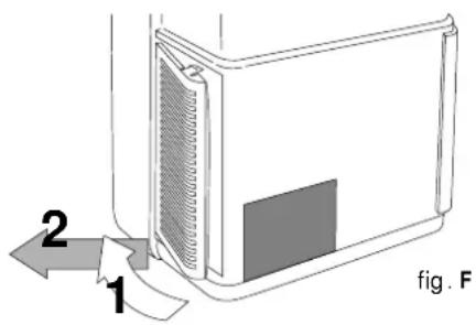
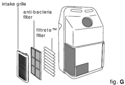
The air purification filters are located behind the two intake grilles. The grilles in fact house the filters themselves.
To clean the filters:
- Remove the intake grilles by rotating them outwards.
-
Remove the first FILTRETE TM filter (white).
-
Remove the filter holder holding the antibacteria filter by unhooking it from the external grille.
ENGLISH
To remove dust deposited on the anti-bacteria filter, use a vacuum cleaner. If very dirty, rinse repeatedly in warm water at a temperature of not more than 40° C.
After washing, dry the filter. To replace, put the filters back into the filter holder, then hook the latter to the unit.
Do not clean the FILTRETE™ filter as this would reduce its filtering capacity.
END OF SEASON OPERATIONS
Take out the condensation tank located in the rear of the unit and empty it.
Empty the residual water by removing the bung in the drainage tube.
After replacing the bung, put the condensation tank back.
Clean the anti-bacteria filters and dry well before replacing.
BEGIN OF SEASON CHECKS
Check that the power cable and socket are undamaged and that the earth installation is efficient.
Troubleshooting
PROBLEMS CAUSES SOLUTIONS
| The air conditioner doesn't work | the power is offthe plug is not inserted into the electrical outletthe fan is blockedthe security float was triggered | plug in the appliancecall the Service Centreempty the basin |
| The air conditioner works for a short time only | the exhaust tube is twistedthe exhaust tube is blockedthe drain tube is bent | position exhaust tube correctlycheck if there are obstacles blocking the exhaust of air out of the applianceunbend the tube |
| The air conditioner works but doesn't cool the room | windows opena heat source is operating in the room (bur-er, light, etc.) or there are a lot of peoplethe exhaust tube has come out of placeair filters cloggedthe output of the unit is insufficient for the conditions or size of the room | close the open windowremove the heat sourcerinsert the tube into its placeclean the filter or replace |
| Strange odour in the room | air filters dirty | clean the filter or replace it |
| Leaking condensation from the unit around of the conditioner | condensation collection basin is fullincorrect installation of the appliance | empty the basin and drain the water with the drainage tube found on the back side of the appliancesee page 16 to properly install the appliance |
| The air conditioner doesn't work for about 3 minutes from turning on the appliance | the appliance's security system has interve-ned | wait for 3 minutes |
The warning light
12 is on
- condensation collection basin is full • Empty the basin.
If the light is still on, consult the Service Centre
Technical specification
RECOMMENDED OPERATING CONDITIONS
Room temperature 21 ÷ 32°C
Outside temperature 21 ÷ 43°C
TECHNICAL SPECIFICATION
Power supply see rating plate
Max. absorbed power in air conditioning "
Max. absorbed power when dehumidifying "
Refrigerating capacity* "
Number of fan speeds 2
Dimensions of the unit:
- width 452 mm
- height 800 mm
- depth
- weight 33,5 kg
* Standard conditions:
Room temperature 27°C
47% relative humidity
Outside temperature
35°C
41% relative humidity
The transportation, loading, cleaning, recovery, and breaking down of the refrigerant agents must be effected only by the technical service centres authorised by the manufacturer.
The break down of the appliance must be done only by specialised personnel authorised by the manufacturer.
CLIMATISATION AVEC INSTALLATION
PROBLEMES CAUSES SOLUTIONS
* Conditions standards:
HET APPARAAT UIT TE SCHAKELEN
OM HET APPARAAT HELEMAAL AF TE ZETTEN, DE FUNCTIEKEUZEKNOP WEER OP "O" ZETTEN EN DE STEKKER UIT HET STOPCONTACT HALEN.
HET AANSLAAN VAN DE GEKOZEN FUNCTIES KAN ENIGSZINS VERTRAAGD GESCHIEDEN TEN OPZICHTE VAN HET DRAAIEN VAN DE KEUZEKNOP.
CONTROLELAMPJES
PROBLEMAS CAUSAS SOLUÇÕES
5751007300/02.01