
3CF540SI BUT - Cooker FAGOR - Free user manual and instructions
Find the device manual for free 3CF540SI BUT FAGOR in PDF.
| Brand | Fagor |
| Model | 3CF540SI BUT |
| Product type | Cooker |
| Category | Gas and electric cooker |
| Height (work surface) | 85 cm |
| Width | 54 cm |
| Depth (door closed) | 54 cm |
| Oven volume | 54 L |
| Power supply type | Gas (G20, G25, G30, G31) and Electricity (230 V) |
| Nominal flow auxiliary burner | 1.00 kW |
| Nominal flow semi-rapid burner | 1.65 kW |
| Nominal flow rapid burner | 2.80 kW |
| Nominal flow oven burner | 3.00 kW |
| Nominal flow gas grill | 2.00 kW |
| Electric plates | ∅145 (normal 1.0 kW, rapid 1.5 kW) and ∅180 (normal 1.5 kW, rapid 2.0 kW) |
| Oven functions | Static oven, gas and/or electric grill, lighting |
| Safety device | Thermocouple on oven and grill burners |
| Cleaning | Soapy water, non-abrasive detergents |
| Certifications | Compliant with EEC directives 90/396, 2006/95/EC, 2004/108, 1935/2004 |
| Included accessories | Chrome grill, Drip tray, Knob guard |
Frequently Asked Questions - 3CF540SI BUT FAGOR
User questions about 3CF540SI BUT FAGOR
0 question about this device. Answer the ones you know or ask your own.
Ask a new question about this device
Download the instructions for your Cooker in PDF format for free! Find your manual 3CF540SI BUT - FAGOR and take your electronic device back in hand. On this page are published all the documents necessary for the use of your device. 3CF540SI BUT by FAGOR.
USER MANUAL 3CF540SI BUT FAGOR
Characteristicas techniques
0 145 1,0 kW - Placa normal
Además, según los modelos, las cocinasSEOSEOSEOSEOSEOSEOSEOSEOSEOSEOSEOSEOSEOSEOSEOSEOSEOSEOSEOSEOSEOSEOSEOSEOSEOSEOSEOSEOSEOSEOSEOSEOSEOSEOSEOSEOSEOSEOSEOSEOSEOSEOSEOSEOSEOSEOSEOSEOSEOSEOSEOSEOSEOSEOSEOSEOSEOSEOSEOSEOSEOSEOSEOSEOSEOSEOSEOSEOSEOSEOSEOSEOSEOSEOSEOSEOSEOSEOSEOSEOSEOSEOSEOSEOSEOSEOSEOSEOSEOSEOSEOSEOSEOSEOSEOSEOSEOSEOSEOSEO SEOEO SEOEO SEOEO SEOEO SEOEO SEOEO SEOEO SEOEO SEOEO SEOEO SEOEO SEOEO SEOEO SEOEO SEOEO SEOEO SEOEO SEOEO SEOEO SEOEO SEOEO SEOEO SEOEO SEOEO SEOEO SEOEO SEOEO SEOEO SEOEO SEOEO SEOEO SEOEO SEOEO SEOEO SEOEO SEOEO SEOEO SEOEO SEOEO SEOEO SEOEO SEOEO SEOEO SEOEO SEOEO SEOEO SEOEO SEOEO SEOEO SEOEO SEOEQ
RECOMMANDATIONS IMPORTANTES:
Technical data and specific cations 36
Installation 37-40
Ventilation 37
Positioning 37
Gas connection 37
Adapting to different types of gas 38
Replacing the injectors 38
Regulating the air 39
Minimum setting 39
Electrical connection 39
Safety device 40
For the user 40-44
Ventilation 40
Igniting the burners 40
Igniting the gas oven 40
Igniting the gas grill 40
Safety device 41
Using the gas hob 41
Using the electric hot-plates 41
Using the gas oven 41
Using the gas or electric grill 42
Using the static electric oven "4 New" 42
Using oven accessories 43
Removing the oven door 43
Advice and precautions 43
European Directive 2002/96/EC (WEEE) 44
European Regulation 1935/2004....44
Figures 45-47
- Thank you for choosing one of our quality products, capable of giving you the very best service. To make full use of its performance features, read the parts of this manual which refer to your appliance carefully. The Manufacturer declines a responsibility for injury or damage caused by poor installation or improper use of the appliance.
- To ensure its appliances are always at the state of the art, and/or to allow constant improvement in quality, the manufacturer reserves the right to make modification without notice, although without creating difficulties for users
-
When ordering spare parts, inform you dealer of the model number and serial number punched on your appliance's nameplate, visible inside the warming compartment (if present) or on the back of the cooker.
-APPLIANCE COMPLYING WITH THE FOLLOWING DIRECTIVES: -
EEC 90/396
- 2006/95/EC Low Voltage (replaces
73/23/ EEC and subsequent amendments)
- EEC 2004/108 (radio-frequency interference)
- European Regulation 1935/2004 (materials in contact with food))
- EEC 40/2002
- EEC 92/75
-2002/96/EC (WEEE)
FOREWORD
- Refer only to the headings and section covering accessories actually installed on your cooker.
GB
Technical data and specifications
| Nominal external dimensions | Cookers 55x55 |
| Height at hot | cm. 85 |
| Height with lid raisec | cm. 137 |
| Height with glass lid | cm. 137,3 |
| Depth with door closec | cm. 54 |
| Depth with door oper | cm. 100 |
| Width | cm. 54 |
| Usable dimensions | Oven |
| Width | cm. 39,5 |
| Depth | cm. 43,0 |
| Heigh | cm. 32,0 |
| Volume | 1. 54 |
GAS BURNERS (injectors and fIow-rates
| Gas | Burner | Inye- ctoi | Low flow-rate (kW) | Nominal flow-rate (kW) |
| G20 | auxiliar | 77 | 0,4C | 1,0C |
| 20 | semi-rap. | 97 | 0,4C | 1,65 |
| mbar | rapid | 123 | 0,85 | 2,80 |
| oven | 13C | 1 C0 | 3,00 | |
| grill | 11C | 2,00 | ||
| G30 | auxiliar | 50 | 0,4C | 1,0C |
| 28-3C | semi-rap. | 65 | 0,4C | 1,65 |
| mbar | rapid | 83 | 0,85 | 2,80 |
| G3· | oven | 86 | 1 C0 | 3,00 |
| 37 | grill | 70 | 2,00 | |
| mbar |
Cat.: see nameplate on cover; Class 1 or 2.
Type "X" cooker
ELECTRIC HOTPLATES
0 145 1,0 kW - Normal hotplate
1,5 kW - Rapid hotplate
0 180 1,5 kW - Normal hotplate
2,0 kW - Rapid hotplate
HEATING ELEMENT POWERS
bottom element 1.5 kW
top element 0.7 kW
grill 2.0 kW
oven light 15
W
All models are equipped with safety device for oven and grill burners.
Depending on the models, cooker may also have:
- Oven thermostat
- Electric oven lighting
- Grill burner or element
- One or more electric hotplates
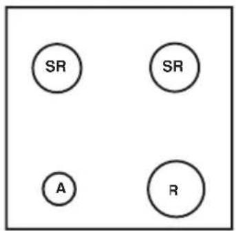
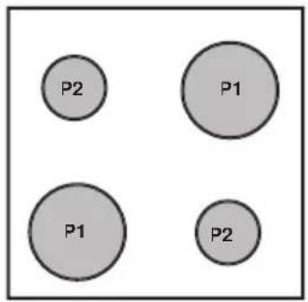
For the LAYOUT OF HOB BURNERS see the models illustrated in figure 1 at the back of this manual.
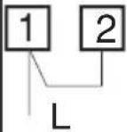
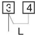
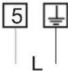
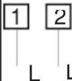
For the ELECTRIC WIRING DIAGRAM see fi gure 2 at the back of this manual The electrical power is stated on the nameplate visible inside the warming compartment (if present) or on the back of the cooker.
A copy of the nameplate is glued to the cover of this manual (for gas or gas-electric products only).
GB
Installation
Useful information concerning the energy consumption of electric ovens.
This information completes and expands on the figures provided on the technical data sticker supplied with the instruction manual.
| Cooker 55N Static | |
| EU environmental quality mark. | Nc |
| Time required to cook a normal load ir conventional mode in minutes. | 53,4 |
| Time required to cook a normal load in fan mode in minutes | .. |
| Power consumption in stand-by setting in Watts. | .. |
| Usable area of the dripping pan in cm2 | 115€ |
INSTALLATION
The appliance must be installed by qualified staff working in accordance with the regulations in force.Before installing, ensure that the appliance is correctly preset for the local distribution conditions (gas type and pressure). The preset settings of this appliance are indicated on the nameplate shown on the cover. This appliance is not connected to a gas extractor device. It must be installed an connected in accordance with the regulation in force. This appliance may only be installed and may only operate in rooms permanently ventilated in accordance with national regulations in force
VENTILATION
The rooms in which gas appliances are installed must be well ventilated in order to al correct gas combustion and ventilation The air flow necessary for combustion is at least 2m^3 /h for each kW of rated power
POSITIONING
Remove the packaging accessories, including the fi Ims covering the chrome-plated ar stainless steel parts, from the cooker. Posit the cooker in a dry, convenient and draft-free place. Keep at an appropriate distance from walls which may be damaged by heat (wood linoleum, paper, etc.). The cooker may be free-standing (class 1) or between two units (in class 2 st 2-1) the sides of which must withstand a temperature of 100^ and which must not be higher than the working table "Class 1" means the appliance should no be built into cabinets. The minimum clearar between the appliance and kitchen cabinets on either side situated beneath the worktop the lid when closed is 20mm . The minimum clearance between the appliance the wa on either side is 20~cm . In the presence of a cooker hood, the latter should be situated at least 65~cm above the worktop, and adjacent cabinets should be at least 42~cm away. If there is no cooker hood, the cabinet installe in its place should be situated at least /0 cm away.
"Class 2 subclass 1" means the appliance should be built in between two cabinets. The minimum clearance between the appliance the wall on either side is 20cm . In the presence of a cooker hood, the latter should be situated at least 65cm above the hob, and adjacent cabinets should be at least 42cm away. If there is no cooker hood, the cabinet installed in its place should be situated at least 70cm away.
"Type X kitchen" refers to the method for connection of the power supply cable (fl exi cable), which must be such as to allow easy replacement.
CONNECTING TO THE GAS SUPPLY
Before connecting the cooker, check that it is preset for the gas to be used. Otherwise make the conversion as described in the section headed "Adapting to different ga types". The connection is on the right; if the pipe has to pass behind the cooker, it must
GB
Installation
be kept low down where the temperature is about 50 degrees C
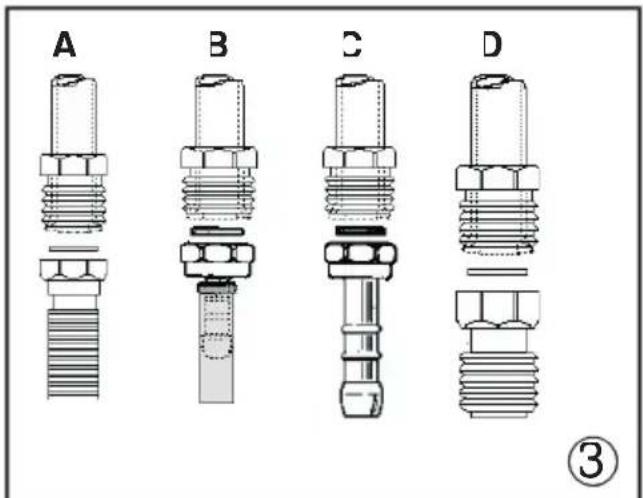
Rigid connection (see fi g. 3A + C) The connection to the mains gas supply m be made using a rigid metal pipe or with a metal hose. Remove the hose connector (if already fi tted) and screw the rigid union onto the threaded connection of the gas tr see fi g.3D).The union for rigid connection may already be fi tted on the gas train, or may be amongst the cooker accessories. Otherwise, it can be obtained from you dealer.If national regulations permit, a meshose complying with the national standard can be screwed directly onto the threaded connection of the gas train, fi tting a seal see fi g.3A).However, users are strongly recommended always to fi t the rigid unio
- Connection using a rubber hos (see fig 3C). (For butane/propane gas only) Connect a rubber hose carrying the conformity mark currently in force to the hose connector. The hose must be replaced at the date indicated at the latest, ad must be secured at both ends using standard hose clamps. It must be absolutely accessible to allow its condition to be checked along its entire length
CAUTION
- Use of the hose connector is only permitted for free-standing installation. If the appliance is installed between two class 2 st. 2-1 unions, the rigid union is the only form of connection permitted
IMPORTANT:
- Use only standard rubber hoses. For LPG use a hose which complies with the nation regulations in force
- Avoid sharp bends in the pipe and keep it well away from hot surfaces
References to the regulations covering the gas connection to the appliance: ISO 7-1
ADAPTING TO DIFFERENT TYPES OF GAS
If the cooker is not already preset to operate with the type of gas available, it must be
converted. Proceed as follows
- Replace the injectors (see table on page 36):
- regulate the primary air flow
- regulate the minimum settings
N.B.: every time you change the type of gas indicate the new type of gas on the serial number label
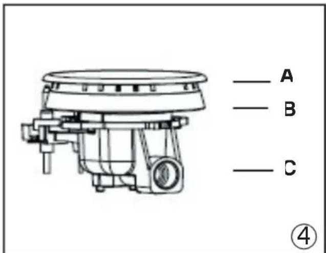
REPLACING THE HOB BURNER INJECTORS (fi g. 4
- Remove the grid, the burner caps A), and the burners E);
- Unscrew and remove the injector in the bottom of each injector holder C);
- replace the injector in accordance with the table in page 36 tighten and screw right down:
- check that the system is gas-tight
- replace the burners, the burner caps and 1 grid.
- remove the mixer pipes and replace the injectors using a 7 mm socket wrench
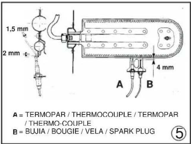
REPLACING THE OVEN BURNER INJECTOR (Fig. 5)
- Loose the screw securing the oven bottom
- remove the oven bottom (push back and raise)
- remove the oven burner, after taking out it
fi xing screw - replace the injector, using a 7 mm socket wrench.
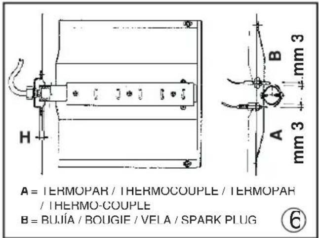
REPLACING THE GRILL BURNER INJECTOR (Fig. 6)
- Remove the burner after taking out the two screws which secure it
- replace the injector using a 7 mm socket wrench
IMPORTANT:
- Never over-tighten the injectors
- after replacing, check that all the injectors are airtight
REGULATING THE BURNER AIF
Refer to the table below for regulation of the
GB
Installation
gap H in mm (fi g. 6 for the grill)
| Burner | G20 20mbar | G30 28-30mbar 31 37mbar |
| Over | - | - |
| Grillr | 4 | 8 |
Check operation of the burner
- Ignite the burner at maximum fl am
- the tongue of the fl ame must be clear and with no yellow tip, and must adhere close to the burner. If too much air is supplied, fl ame detaches from the burner and may dangerous. If the air supply is insufficient the fl ame has a yellow tip and soot may form.
SETTING HOB BURNER MINIMUM LEVELS
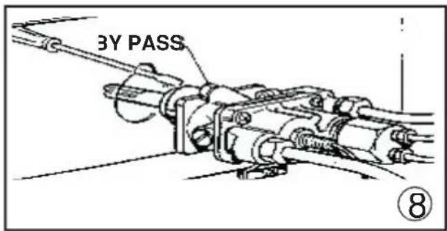
If the cooker is to work on bottled gas (buta propane), the tap by-pass must be screwed right down. The cooker may be equipped with type A taps, with by-pass inside (accessed inserting a small screwdriver into the rod) or type B taps, with by-pass on the outside on right (accessed directly). See ti gure If the cooker is to work on natural gas, process follows for both types of tap
- Ignite the burner at maximum fl am
- pull off the knob, without using a level against the control panel, which might be damaged
- access the by-pass with a small screwdriver and back off by about 3 turns (turning the screwdriver anti-clockwise)
- turn the tap rod anti-clockwise again until it stops: the burner will be at maximur flame
- screw the by-pass slowly back in, without pushing the screw-driver, until the fl amel apparently shrunk to 1/4 of the maximum size, checking that it is sufficiently stable even in quite strong draughts
SETTING OVEN BURNER MINIMUM LEV-ELS
If the cooker is to work on bottled gas (butane/propane), the thermostat by-pass must be screwed right down. If the cooker is to work on natural gas, proceed as follows
- Remove the oven bottom (push towards the back and raise)
- Ignite the oven burner, turning the kno pointer to the maximum setting
- shut the oven door
- access the thermostat or tap by-pass (see fig. 8)
- back off the thermostat by-pass by about 3 turns
- after 5 or 6 minutes, turn the knob pointer the minimum setting
- slowly re-tighten the by-pass, watching the fl ame decrease in size through the window the closed oven door until the tongue of the fl ame is about 4mm long. Never keep the fl ame too low. It must be stable even when the oven door is opened or closed quickly
- turn off the burner and replace the oven bottom
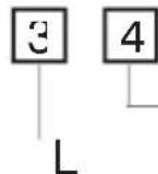
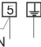
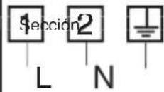
CONNECTING TO THE ELECTRICAL MAINS
Before making the connection, check that
-
the mains voltage is as indicated on the nameplate
-
the earth connection is in good working order.
Except in the case where the appliance is fitted with a power supply cable featuring a plug, and the same remains accessible after installation is completed, the fi tter should insert an omnipolar switch with a minimum contact opening of 3mm .If the appliance is fitted with a power supply cable without a plug, the connection can be made by addin a standard-compliant plug or a connection bridge directly. When making this connectic keep the following in mind
- the yellow-green wire should be connected to the earth connection
- the blue wire to neutral
GB Installation For the user
- the brown wire to phase
- the lead must never touch hot surfaces ove about 75 degrees C
- replacement leads must be of type H05RH F or H05V2V2-F of suitable size (see diagrams in fig. 2)
- if the appliance is supplied without lead using type H05RR-F or H05V2V2-F cable of suitable size (see diagrams in Fig. 2)
IMPORTANT: the manufacturer declines all liability for damage due to failure to comply with the regulations and standards in force. Check that the appliance is correctly connected to the earth (see diagrams in fig. 2 at the back of the manual).
THE SAFETY DEVICE
The correct gap between the end of the the mocouple sensor and the burner is shown in figures 5 and 6. To check that the valve is working properly, proceed as follows:
- ignite the burner and leave it to work for about 3 minutes
- turn off the burner by returning the knob to off position () ;
- after 60 seconds for oven and grill burners turn the knob pointer to the "on" position
- release the knob in this position and move a burning match towards the burner; I1 MUST NOT IGNITE
Time needed to excite the magnet during ignition: 10 seconds approx. Automatic tripping time, after fl ame has been turned off: not more than 60 seconds for oven and grill burners.
IMPORTANT:
- Before doing any work inside the cooker, disconnect the mains plug and shut the gas tap.
- Never use matches to check the gas circu for leaks. If a specific control device is no available, foam or very soapy water can b used
- When re-closing the hob, check that the electrical wires of the spark plugs (present) are not close to the injectors, so that they cannot run across them.
HOW TO USE THE COOKER
VENTILATION
All gas cooking appliances produce heat and moisture in the rooms where they are installed. Take care to ensure that the kitchen is well ventilated; keep the ventilatic openings unobstructed or install an extracto hood with tan.
In case of intensive or prolonged use, additional ventilation may be required; open a window, or increase the extractor fan power.
IGNITING THE HOB BURNERS
- Press the knob and turn it anti-clockwise until it reaches the symbol on the contro panel (maximum fl ame position)
- at the same time, move a burning match towards the burner head;
- to reduce the fl ame, turn the knob further the same direction until its pointer is again the symbol (minimum fl ame position)
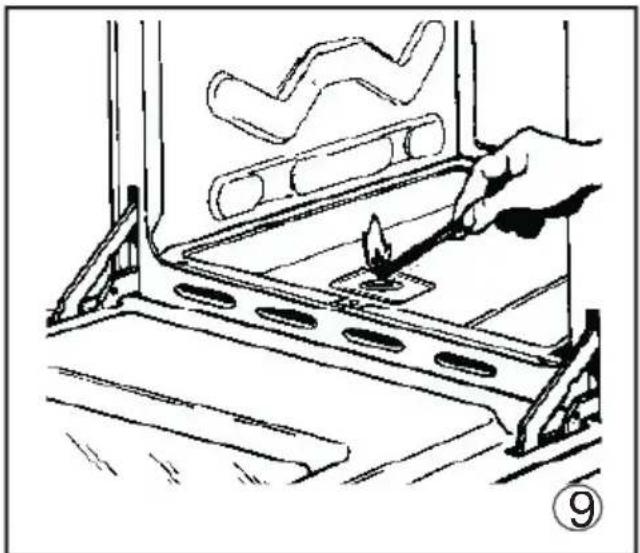
IGNITING THE OVEN BURNER
- Open the oven door;
- press the knob and turn it anti-clockwise to the maximum 11 ame position
- move a burning match towards the hole in the centre of the oven bottom and press the knob right down (see fig. 9)
- look through the two holes in the sides of the bottom to check that the burner has ignited, keeping the knob pressed down;
- after about 10 seconds, release the knob and check that the burner remains on. Otherwise, repeat the operation
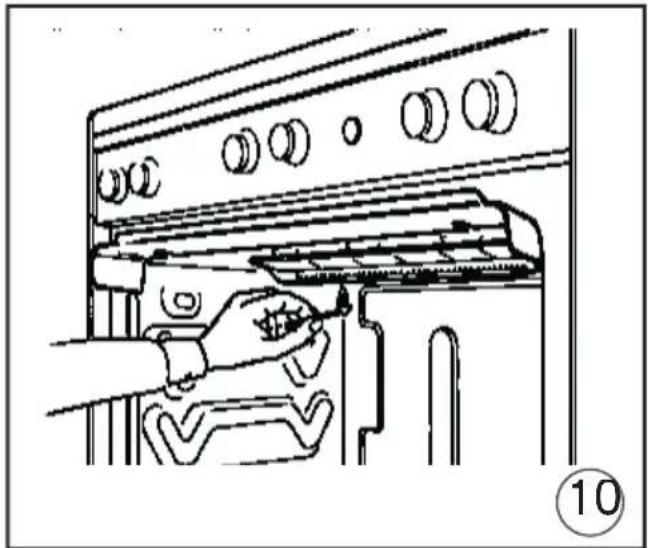
IGNITING THE GRILL BURNER (GAS GRILLS)
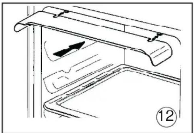
- Fit the control knob guard as shown in fig 12
- press the oven knob and turn it to the right until it reaches the stop;
- move a burning match towards the perforated burner pipe and press the knob right down (see fig. 10)
GB For the user
- check that the burner has ignited, keeping the knob pressed down;
- after about 10 seconds, release the knob and check that the burner remains on. Otherwise, repeat the operation.
SAFETY DEVICE
Burners equipped with this device have the advantage that they are protected if they accidentally go out. If this occurs, the supply gas to the burner concerned is automatically cut off, preventing the hazards deriving from a leak of unburnt gas. The gas supply must be cut off within no more than 60 seconds for the oven and grill burners.
IMPORTANT:
- Diffi culty in igniting burners is normal if the cooker has been out of use for some time. The air accumulated in the pipes will be expelled in a few seconds;
- Never allow too much unburnt gas to flow from the burners. If ignition is not achieved within a relatively short time, repeat the procedure after returning the knob to the off position () ;
- when the oven and grill are lit for the first time, a smell may be noticed and smoke may come out of the oven. This is because of the surface treatment and oily residues on the burners.
HOW TO USE THE HOB BURNERS
Use pans of diameter suitable for the burn type. The fl ames must not project beyond base of the pan. Recommended sizes:
- for auxiliary burners = pans of at least 8 ci using the adjusting grid supplied with the cooker
- for semi-rapid burners = pans of at least 1 cm
- for rapid and double fl ame burners = pal of at least 22 cm.
N.B.: Never keep the knob at settings between the maximum fl ame symbol and the off position () .
FOR COOKERS EQUIPPED WITH ELECTRIC HOTPLATES
The different heat settings are obtained as follows:
- 1 = minimum setting for all hotplates;
- 6 = maximum setting for normal and rapid hotplates (with red disc)
-0=off.
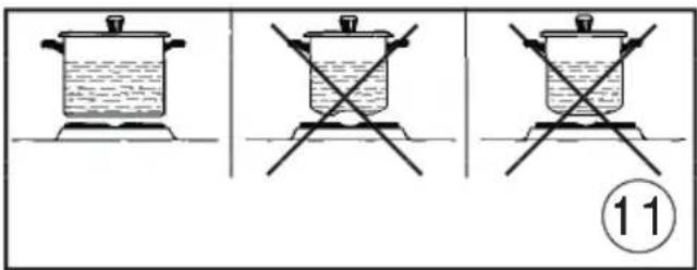
Pans must never be smaller in diameter than the hotplates and their bottoms must be as fl at as possible (see fig. 11
IMPORTANT:
- Never leave hotplates on without pans, except when first used; leave for about 10 minutes to dry oil or moisture residues
- if the hotplate is to be out of use for a long time, apply a little grease to its painted surface;
- do not allow spills to burn onto the hotplate requiring the use of abrasive cleaners
- After igniting the burner, leave the oven to heat up for about 10 minutes;
- place the food for cooking in an ordinary oven dish and place it on the chrome-plate shelf;
- place in the oven on the highest possible runners, and turn the knob pointer to the setting required;
- cooking can be observed through the window in the door with the oven light on. This will avoid opening and closing the do frequently, unless oil or fat has to be adde to the dish.
N.B.: For cookers without thermostat
with the knob on the maximum setting = 2 / 0 degrees C
- with the knob on the minimum setting = 150 degrees C
- All other temperatures between 150 and 270 degrees C are obtained approximately by positioning the knob between the maximum and minimum settings.
Never leave the knob in positions between the maximum symbol and the off setting () .
GB
For the user
- fit the knob guard (see fig. 12
- light the burner and wait a few minutes to give the burner time to warm up;
- place the foods on the chrome-plated shelf;
- insert on the highest runner
- insert the drip tray on the bottom runner
- gently close the oven door, resting it again the knob guard;
- after a few minutes, turn the food to expo the other side to the infrared radiation (the cooking time depends on the type of food and personal taste).
The table below "Food to be grilled" will serve as a guide.
| Food to be grilled | Time (minutes) | |
| 1st side | 2nd side | |
| Thin pieces of meat | 6 | 4 |
| Fairly thick pieces of meat | 8 | 5 |
| Thin fi sh or fi s without scale | 10 | 8 |
| Fairly thick fi sh | 15 | 12 |
| Sausages | 12 | 10 |
| Toasted sandwiches | 5 | 2 |
| Small poultry | 20 | 15 |
N.B.: the first time the grill is used smoke will come out of the oven. Before inserting food for cooking, wait until any oil residues on the burner have completely burnt away. The grill must only be used at its full rated heat.
IMPORTANT: accessible parts may be hot when the grill is in use! Keep children well away.
HOW TO USE THE ELECTRIC GRILL WITH GAS OVEN
- ignite the grill heating element
- place the foods on the chrome-plated shelf;
- insert on the highest runner
-
insert the drip tray on the bottom runner
-
gently close the oven door;
- after a few minutes, turn the food to expo the other side to the infrared radiation (the cooking time depends on the type of food and personal taste).To see table "Food to be grilled"
The grill element in the top of the oven is switched on by turning the thermostat knob clockwise to the grill symbol on the control panel.
The red light will come on to show the element is in operation.
STATIC ELECTRIC OVEN " 4 New "
With different heating elements controlled using a selector switch and regulated by a thermostat, starting from the 0 (off) position the knob can be turned clockwise to the following settings:
- symbol :oven lamp on (it will remain on even if the knob pointer is turned to the other settings).
- symbol : slow cooking using the bottom element; the oven temperature is regulated using the thermostat knob
- symbol : conventional "static" oven cooking, the oven temperature is controlle using the thermostat knob
symbol :grill on.
N.B. - The yellow light switches on and off as the thermostat is tripped.
Before placing food inside, allow the oven to heat up for at least 10 minutes.
HOW TO USE THE ELECTRIC GRILL WITH ELECTRIC OVEN
- For models with "Electric Oven" only, controlled by two knobs separately ( selector - thermostat),grilling is permitted with the door closed, without using the front side.Temperatures above 200^ must not be used when grilling with the door closed.
GB For the user
USING OVEN ACCESSORIES
- The oven shelf is designed to take normal oven dishes for cooking sweets or roasts, or is used without a pan for cooking foods under the grill.
- The drip pan under the grill is used to collect juices, which drip from the food that is cooked directly on the grill. The drip par can also be used for cooking.
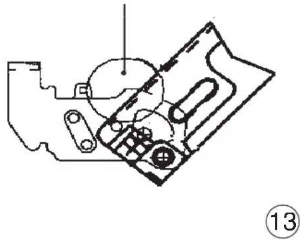
REMOVING THE OVEN DOOR
The door can be removed for easier oven cleaning, proceeding as follows:
- fully open the door.
- insert two small coins (e.g. 10 Euros) into the two slots in the hinges.
- close the door until the coins start to prevent it closing further (fig. 13)
- close the door some more and lift it off, holding it at the sides and moving it slightly forward; this is the point at which the door can be removed easily.
- to put the door back in place, return the hinges to their positions, checking that the have fitted into their seats
- lower the door completely and remove the coins inserted earlier.
- fully close the door.
- always inspect the oven door gasket and i worn have it replaced at once by the after sales service.
GENERAL PRECAUTIONS
- Always disconnect the power supply before any work inside the oven or where live parts may be accessed.
- Never use the warming compartment for storing infl ammable liquids or items which do not withstand heat, such as wood, paper aerosol cans, matches, etc.
- Make frequent checks on the rubber connection hose, ensuring that it is well away from hot surfaces, that there are no sharp bends or kinks, and that it is in good condition. The hose must be replaced at the latest at the indicated date and must be secured at both ends using a standard hos
clamp.
- If taps become stiff to operate over time, contact the After-Sales service.
- Wash enamelled or chrome-plated parts with soapy lukewarm water or non-abrasiv detergents. A metal brush may be used to remove deposits from hob burners and flame caps. Dry thoroughly
- Never use abrasives to clean enamelled or chrome-plated parts
- Do not use too much water when washing the hob. Take care that no water or other substances enter the burner housing hole as this may be dangerous.
- The spark plugs for electric ignition must be kept clean and dry; always check after use, particularly if there have been drips or overflows from pans
- Never close glass lids until the hob burners or hotplates have cooled completely; i might shatter or crack
- Never knock enamelled parts or ignition spark plugs (where present).
- The main or wall gas tap should be turned off when the cooker is not in use
- Never move the cooker by means of the handle.
No liability is accepted for injury or damage caused by poor installation or improper use of the cooker.
In case of malfunctions, particularly gas leaks or short-circuits, contact your engineer without delay.
GB For the user
EUROPEAN DIRECTIVE 2002/96/EC (WEEE): INFORMATION FOR THE CONSUMER

Fig. A
This information is strictly addressed to those who have a product showing the symbol below (Fig.A). This symbol is indicated on the technical data sticker (rating label) placed on the product itself.
This symbol indicates that the appliance is considered as Waste Electrical and Electronic Equipment and complies with the European directive 2002/96/EC (WEEE). Therefore this product is not to be treated a household waste. Instead it shall be handed over to the applicable collection point for the recycling of electrical and electronic equipment or it can be handed back to the retailer when you want to purchase a new equivalent product. The consumer is responsible for a correct disposal of the product towards an appropriate collection point. Otherwise the consumer can be exposed to a penalty sanction by laws in force for waste disposal. Appropriate separate waste collection followed by recycling the product, the treatment and compatible environmental disposal contributes to avoid negative effects towards the environment and health and helps to recycle material which the product is composed of. For more detailed information regarding the available waste collection systems of this product please contact your local city office or contact the retailer where the product was purchased.
The manufacturers and importers will obey to their responsibility for recycling, treatment and compatible environmental disposal by participating directly and through a joint cooperative system.
EUROPEAN REGULATION NO 1935/2004 - MATERIALS IN CONTACT WITH FOOD, NOTICE TO USERS.

The symbol shown here, which appears on the packaging, indicates that the materials in this product which may come into contact with food are compliant with the requirement of European Regulation No 1935/2004.
Inside the oven chamber, food might come into contact with oven shelves, dripping pans, pastry trays, oven door glazing, rubber gaskets, rotisserie spits, and the sides of the oven itself.
On the hob, contact is possible with pa.
stands, burners and the hob skin.
In the food-warmer, contact may occur with the sides of the compartment.
Figuras / Figures / Figuras / Figures
A = AUXILIAR
AUXILIAIRI
AUXILIAR
=AUXILIARY
R = RAPIDO
RAPID
- RAPIDO
- RAPID
P2-PIACA 0145
PLAQUE 145
=DISCO 145
= HOTPLATE 0145
SR = SEMIRRAPIDO
SEMI-RAPIDE
SEMI-RAPIDO
=SEMI-RAPID
P* = PLACA
PLAQUE
0180
0 180
0 180
0180
①
A
B
(3)
Section cable Sec. cabc
Wire gauge
3 × 6 ~mm^2
230 V TRIFASICO/TRIPHASE/TRIFASICO/THREE-PHASE
Seccion cable
Section cable
Sec. cabc
Wire gauge
4 × 4 ~mm^2
400VTRIFASICO+NEURO/TRIPHASE+NEUTRE/
TRIFASICO + NEUTRO / THREE-PHASE + NEUTRAL
Seccion cable
Section cable
Sec. cabc
Wire gauge
5x2.5mm
230 V BIFASICO/BIPHASE/BIFASICO/TWO-PHASE
3.5kW
2.2 - 3.5 kW
0-2,2 kW
3x2,5 mm²
3x1.5 mm²
3x1 nm²
cable
Section cable
Sec. cabc
Wire gauge

Figuras / Figures / Figuras / Figures

Figuras / Figures / Figuras / Figures
Pour extraire la porte, utiliser deux pieces de 10 centimes.
To remove the door, use two 10 Eurocents. Para extraer la puerta用工 dos monidas de 10 centeos. Para extrair a porta, utilizing dos moedas de 10 centimos.

- Characteristicas techniques
- RECOMMANDATIONS IMPORTANTES:
- FOREWORD
- GB
- Technical data and specifications
- ELECTRIC HOTPLATES
- HEATING ELEMENT POWERS
- Installation
- Useful information concerning the energy consumption of electric ovens.
- VENTILATION
- POSITIONING
- CONNECTING TO THE GAS SUPPLY
- CAUTION
- IMPORTANT:
- ADAPTING TO DIFFERENT TYPES OF GAS
- REPLACING THE HOB BURNER INJECTORS (fi g. 4
- REPLACING THE OVEN BURNER INJECTOR (Fig. 5)
- REPLACING THE GRILL BURNER INJECTOR (Fig. 6)
- REGULATING THE BURNER AIF
- SETTING HOB BURNER MINIMUM LEVELS
- SETTING OVEN BURNER MINIMUM LEV-ELS
- CONNECTING TO THE ELECTRICAL MAINS
- GB Installation For the user
- THE SAFETY DEVICE
- HOW TO USE THE COOKER
- IGNITING THE HOB BURNERS
- IGNITING THE OVEN BURNER
- IGNITING THE GRILL BURNER (GAS GRILLS)
- GB For the user
- SAFETY DEVICE
- HOW TO USE THE HOB BURNERS
- FOR COOKERS EQUIPPED WITH ELECTRIC HOTPLATES
- For the user
- HOW TO USE THE ELECTRIC GRILL WITH GAS OVEN
- STATIC ELECTRIC OVEN " 4 New "
- HOW TO USE THE ELECTRIC GRILL WITH ELECTRIC OVEN
- USING OVEN ACCESSORIES
- REMOVING THE OVEN DOOR
- GENERAL PRECAUTIONS
- Figuras / Figures / Figuras / Figures
Brand : FAGOR
Model : 3CF540SI BUT
Category : Cooker