3CF950SXBUT - Cooker FAGOR - Free user manual and instructions
Find the device manual for free 3CF950SXBUT FAGOR in PDF.
| Product type | Gas and mixed cooker (gas + electricity possible) |
| Brand | Fagor |
| Model | 3CF950SXBUT |
| Width | 90 cm |
| Depth (door closed) | 59 cm |
| Depth (door open) | 100 cm |
| Height (worktop) | 85 cm |
| Height (lid open) | 140 cm |
| Oven volume | 119 L |
| Usable oven dimensions (W x D x H) | 75 x 48 x 36 cm |
| Hob burners | Auxiliary, semi-rapid, rapid, ultra-rapid inner/outer |
| Oven burner | Gas burner with thermostat and safety device |
| Grill burner | Gas grill burner with safety device |
| Ignition | Electric for hob burners, oven and grill (depending on model) |
| Gas supply | G20 (20 mbar), G20 (28-30 mbar), G31 (3+ mbar) |
| Electrical supply | 230 V, cable HO5RR-F or H05V2V2-F |
| Oven functions | Traditional cooking, grill, rotisserie |
| Timer | Mechanical, up to 1 hour |
| Oven lighting | Yes, with indicator switch |
| Oven interior coating | Self-cleaning enamel (side and rear walls) |
| Adjustable feet | Yes, for leveling |
| Lid | With balanced springs (depending on model) |
| Safety | Safety device on oven and grill burners; automatic shut-off in case of flame failure |
| Cleaning | Do not use abrasive products; clean spark plugs after each use |
| Spare parts and repairability | Injectors, burners, thermocouple, spark plugs; contact a professional |
| General information | Compliant with EEC Directives 90/396, 73/23, 93/68, 89/336 and EC Regulation 1935/2004; WEEE 2002/96 |
Frequently Asked Questions - 3CF950SXBUT FAGOR
User questions about 3CF950SXBUT FAGOR
0 question about this device. Answer the ones you know or ask your own.
Ask a new question about this device
Download the instructions for your Cooker in PDF format for free! Find your manual 3CF950SXBUT - FAGOR and take your electronic device back in hand. On this page are published all the documents necessary for the use of your device. 3CF950SXBUT by FAGOR.
USER MANUAL 3CF950SXBUT FAGOR
Fitting the oven door handle 26
Gas connection 26
Adapting to different
types of gas 27
Replacing the injectors 27
Minimum setting 27
Electrical connection 28
Electric ignition 28
Safety device 28
For the usei 29 - 33
Ventilation 29
Igniting the burners 29
Igniting the gas oven 29
Igniting the gas gril 30
Safety device 30
Electrical switch-on 30
Using the gas hob 30
Using the gas oven 31
Using the gas gril 31
Using the rotisserie 31
Oven light / rotisserie switch 32
Oven with thermostat 32
Using the self-cleaning oven 32
Using the spring clock 32
Advice and precautions 32
European Directive
2002/96/EC (WEEE) 33
European Regulation N° 1935/2004.....33
Figures 45 - 48
- Thank you for choosing one of our quality products, capable of giving you the very best service. To make full use of its performance features, read the parts of this manual which refer to your appliance carefully. The Manufacturer declines a responsibility for injury or damage caused by poor installation or improper use of the appliance.
- To ensure its appliances are always at the state of the art, and/or to allow constant improvement in quality, the manufacturer reserves the right to make modification without notice, although without creating difficulties for users
- When ordering spare parts, inform you dealer of the model number and serial number punched on your appliance's nameplate, visible inside the warming compartment (if present) or on the back of the cooker.
- APPLIANCE COMPLYING WITH THE FOLLOWING DIRECTIVES:
- EEC 90/396
- EEC 73/23 and 93/88
- EEC 89/336 (radio-frequency interference)
- EUROPEAN REGULATION 1935/2004 (materials in contact with food)
- 2002/96/EC (WEEE)
FOREWORD
- Refer only to the headings and section covering accessories actually installed on your cooker.
GB
Installation
| Nominal external dimensions | Cookers 90x60 |
| Height at hot | cm. 85 |
| Height with lid raised | cm. 14 ^ |
| Depth with door closec | cm. 59 |
| Depth with door oper | cm. 100 |
| Width | cm. 90 |
| Usable dimensions | Oven with grill |
| Width | cm. 75 |
| Depth | cm. 48 |
| Height | cm. 33 |
| Volume | 1. 119 |
GAS BURNERS (injectors and flow-rates
| Gas | Burner | Injector | Low flow-rate (kW) | Nominal flow-rate (kW) |
| G20 | auxiliar | 76 | 0,45 | 1,00 |
| 20 | semi-rap. | 94 | 0,60 | 1,65 |
| mbar | rapid | 128 | 0,95 | 2,90 |
| oven | 135 | 1,20 | 3,30 | |
| grill | 130 | - | 3,00 | |
| ultra-rap. | ||||
| int. | 63 | |||
| ultra-rap. | ||||
| ext. | 140 | 2,10 | 4,25 | |
| G20 | auxiliar | 50 | 0,45 | 1,00 |
| 28-30 | semi-rap. | 65 | 0,60 | 1,65 |
| mbar | rapid | 85 | 0,95 | 2,90 |
| G31-37 | oven | 90 | 1,20 | 3,30 |
| grill | 86 | - | 3,00 | |
| ultra-rap. | ||||
| int. | 37 | |||
| ultra-rap. | ||||
| ext. | 97 | 2,10 | 4,25 |
Cat.: see nameplate on cover; Class 1 or 2.1
Type "X" cookers
EQUIPMENT
All models are equipped with safety device for oven and grill burners.
Depending on the models, cooker may also have
- Safety device for one or more hob burners
- Electric ignition on top burners
- Electric ignition on oven and grill burners
- Self-cleaning enamelled liners
- Oven thermostat
- Electric oven lighting
- Rotisserie
- Grill burner
- Mechanical timer
For the LAYOUT OF HOB BURNERS see the models illustrated in figure 1 at the bac of this manual.
For the ELECTRIC WIRING DIAGRAM see figure 2 at the back of this manua
The electrical power is stated on the name-plate visible inside the warming compartment (it present) or on the back of the cooker.
A copy of the nameplate is glued to the cov of this manual.
GB
Installation
INSTALLATION
The appliance must be installed by qualifi e staff working in accordance with the regulations in force. Before installing, ensure that the appliance is correctly preset for the local distribution conditions (gas type and pressure). The presettings of this appliance are indicated on the nameplate shown o the cover.
This appliance is not connected to a flue gas extractor device. It must be installed and connected in accordance with the regulations in force. This appliance may only be installed and may only operate in rooms permanently ventilated in accordance with national regulations in force.
VENTILATION
The rooms in which gas appliances are installed must be well ventilated in order to allow correct gas combustion and ventilation. The air flow necessary for combustion is at least 2 m^3/h for each kW of rated power.
POSITIONING
Remove the packaging accessories, including the fi lms covering the chrome-plated ar stainless steel parts, from the cooker.
Position the cooker in a dry, convenient and draft-free place. Keep at an appropriate distance from walls which may be damaged by heat (wood, linoleum, paper, etc.).
The cooker may be installed alone or between two kitchen units; in this case, the sides of the units must withstand a temperature of 100 degrees C and they must not be higher than the cooker hob.
FITTING THE FEET (LEVELLING)
Cookers are equipped with adjustable feet to be screwed into their front and rear corners, respectively. The feet allow the height of the appliance to be adjusted, in order to set it flush with the adjoining unit, to level it with other worktops and to ensure even distribution of the liquids in pans. See fig. 3
BALANCING THE LID
Models equipped with plate glass lids are fitted with special balanced springs. These are fitted into the hinge to provide smooth, gentle lid closure.
FITTING OVEN DOOR HANDLE
Fix the handle using the 2 screws provided. See fig. 4
CONNECTING TO THE GAS SUPPLY
Before connecting the cooker, check that it is preset for the gas to be used. Otherwise, make the conversion as described in the section headed "Adapting to different gas types". The connection is on the right; if the pipe has to pass behind the cooker, it must be kept low down where the temperature is about 50 degrees C.
- Rigid connection (see Figure 5, diagram D):
The connection to the mains gas supply may be made using a rigid metal pipe (D). Remove the hose connector and screw th rigid union onto the threaded connection of the gas train. The union for rigid connectic is amongst the cooker accessories.
- Connection using a rubber hos (see Figure 5, diagrams B and C):
Connect a rubber hose carrying the conformity mark currently in force to the hose connector. The hose must be replaced at the date indicated, and must be secured a both ends using standard hose clamps. It must be absolutely accessible to allow its condition to be checked along its entire length.
- Connection using a metal host (see Figure 5, diagram D):
Make the connection using a hose which complies with national standards, screwing it onto the connector with a ring seal, which is delivered amongst the cooker accessories.
- After installation, check that all connections are airtight.
- For operation with butane/propane, check
GB
Installation
that the gas pressure is as indicated on the nameplate.
IMPORTANT:
- Use only standard rubber hoses. For LPG use a hose which complies with the nation regulations in force.
- Avoid sharp bends in the pipe and keep it well away from hot surfaces.
References to the regulations covering the gas connection to the appliance: ISO 7-1.
ADAPTING TO DIFFERENT TYPES OF GAS
If the cooker is not already preset to operate with the type of gas available, it must be converted. Proceed as follows:
- Replace the injectors (see table on page 25);
- regulate the primary air flow
- regulate the minimum settings.
N.B.: every time you change the type of gas indicate the new type of gas on the serial number label.
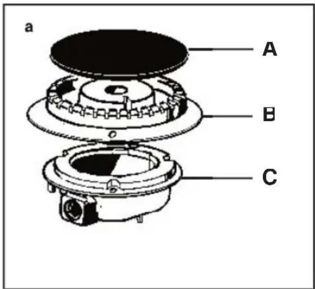
REPLACING THE HOB BURNER INJECTORS (fi g. 6
- Remove the grid, the burner caps (A), and the burners (B);
- Unscrew and remove the injector in th bottom of each injector holder (C);
- replace the injector in accordance with the table in page 25, tighten and screw right down;
- check that the system is gas-tight;
- replace the burners, the burner caps and the grid.
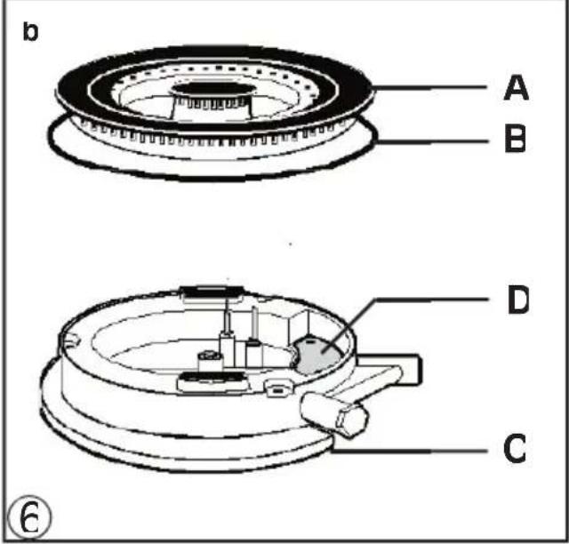
With triple fl ame burners (fi g. 6b
- carry out the operations already described and also
- unscrew the two screws which secure the guard plate (D) and replace the side inject as indicated in the table on page 25, screw in and tighten fully.
IMPORTANT:
- Never over-tighten the injectors;
- after replacing, check that all the injectors are airtight.
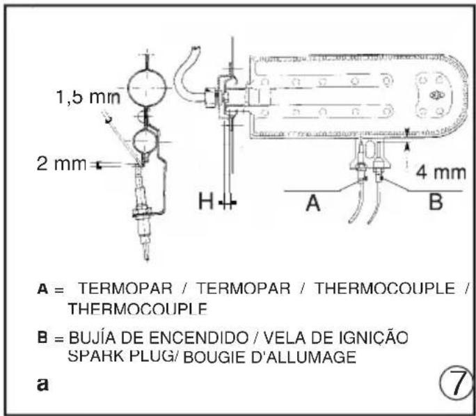
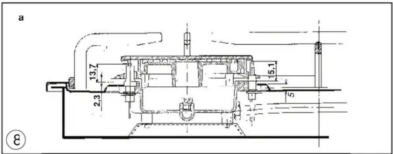
REPLACING THE OVEN BURNER INJECTOR (fi g. 7a
- Loose the screw securing the oven bottom;
- remove the oven bottom (push back and raise);
- remove the oven burner, after taking out it fi xing screw
- replace the injector, using a / mm socket wrench.
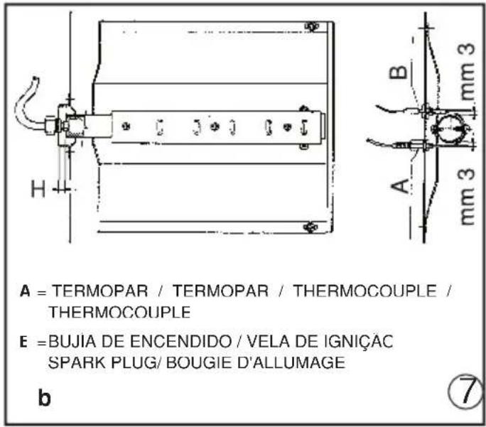
REPLACING THE GRILL BURNER INJECTOR (fi g. 7b
- Remove the burner after taking out the two screws which secure it;
- replace the injector using a 7 mm socket wrench.
IMPORTANT:
- Never over-tighten the injectors;
- after replacing, check that all the injectors are airtight.
SETTING HOB BURNER MINIMUM LEVELS
If the cooker is to work on bottled gas (butane/propane), the tap by-pass must be screwed right down.
The cooker may be equipped with type taps, with by-pass inside (accessed by inse ing a small screwdriver into the rod) or type taps, with by-pass on the outside on the right (accessed directly). See figure 9
If the cooker is to work on natural gas, proceed as follows for both types of tap:
- Ignite the burner at maximum flame
- pull off the knob, without using a level against the control panel, which might be damaged;
- access the by-pass with a small screwdriv and back off by about 3 turns (turning the screwdriver anti-clockwise);
- turn the tap rod anti-clockwise again until it stops: the burner will be at maximum flame
- screw the by-pass slowly back in, without pushing the screw-driver, until the flame has apparently shrunk to 1/4 of the maxi-
GB
Installation
mum size, checking that it is sufficient stable even in quite strong draughts.
SETTING OVEN BURNER MINIMUM LEVELS
If the cooker is to work on bottled gas (butane/propane), the thermostat by-pass mus be screwed right down.
If the cooker is to work on natural gas, proceed as follows:
- Remove the oven bottom (push towards the back and raise);
- ignite the oven burner, turning the kno pointer to the maximum setting
- shut the oven door;
- access the thermostat by-pass (see fig 10)
- back off the thermostat by-pass by about 3 turns;
- after 5 or 6 minutes, turn the knob pointer to the minimum setting;
- slowly re-tighten the by-pass, watching the fl ame decrease in size through the window in the closed oven door until the tongue of the fl ame is about 4 mm long. Never keep the fl ame too low. It must be stable even when the oven door is opened or closed quickly;
- turn off the burner and replace the over bottom.
CONNECTING TO THE ELECTRICAL MAINS
Before making the connection, check that
- the mains voltage is as indicated on the nameplate
- the earth connection is in good working order.
If the socket is not easily accessible, the installation engineer must provide a switch with a contact breaking gap of 3 mm or more.
If the appliance power lead is not fitted with a plug, use an approved standard type, remembering that:
- the green-yellow wire must be used for the earth connection;
- the blue wire is the neutral;
- the brown wire is live;
- the lead must never touch hot surfaces ov about 75 degrees C
- replacement leads must be of type HO5R1 F or H05V2V2-F of suitable size (see diagrams in fig. 2)
- if the appliance is supplied without lead using type HO5RR-F or H05V2V2-F cable of suitable size (see diagrams in fig. 2)
IMPORTANT: the manufacturer declines all liability for damage due to failure to comply with the regulations and standards in force. Check that the appliance is correctly connected to the earth (see diagrams in fig. 2 at the back of the manual).
FOR COOKERS WITH ELECTRIC IGNITION
The correct gaps between the electrode and the burner are shown in figures 7a,7b,8a,8b,
If no spark is generated, do not keep on try as this might damage the generator.
Possible causes of malfunctions
- spark plug damp, dirty or broken;
- electrode-burner gap not correct;
- spark plug wire broken or without sheathing
- spark discharging to earth (to other parts of the cooker)
- generator or microswitch damaged;
- air has built up in the pipes (particularly if the cooker has been out of use for a long time);
- air-gas mixture incorrect (poor fuel setting).
THE SAFETY DEVICE
I he correct gap between the end of the the mocouple sensor and the burner is shown i fi gures 7a,7b,8a,8b
To check that the valve is working properly, proceed as follows:
- ignite the burner and leave it to work for about 3 minutes
- turn off the burner by returning the knob to off position (●);
GB
Installation
For the user
- after 90 seconds for hob burners, 60 seconds for oven and grill burners, turn the knob pointer to the "on" position;
- release the knob in this position and move a burning match towards the burner; IT MUST NOT IGNITE.
Time needed to excite the magnet during ignition: 10 seconds approx.
Automatic tripping time, after tl ame has be turned off: not more than 90 seconds for ho burners; not more than 60 seconds for over and grill burners.
IMPORTANT:
- Before doing any work inside the cooker, disconnect the mains plug and shut the ga tap.
- Never use matches to check the gas circuit for leaks. It a specific control device is not available, foam or very soapy water can be used.
- When re-closing the hob, check that the electrical wires of the spark plugs (if present) are not close to the injectors, so that they cannot run across them.
HOW TO USE THE COOKER
VENTILATION
All gas cooking appliances produce heat and moisture in the rooms where they are installed. Take care to ensure that the kitchen is well ventilated; keep the ventilation openings unobstructed or install an extractor hood with fan. In case of intensive or prolonged use, additional ventilation may be required; open a window, or increase the extractor fan power.
IGNITING THE HOB BURNERS
- Press the knob and turn it anti-clockwise until it reaches the symbol on the contro panel (maximum flame position)
- at the same time, move a burning match towards the burner head;
- to reduce the fl ame, turn the knob further the same direction until its pointer is again the 🔒 symbol (minimum fl ame position)
FOR HOB BURNERS EQUIPPED WITH SAFETY DEVICE
- Press the knob and turn it anti-clockwise until it reaches the symbol on the contro panel (maximum flame position)
- move a burning match towards the burner keeping the knob pressed right down for about 10 seconds;
- then release the knob and check that the burner remains on. Otherwise, repeat the operation.
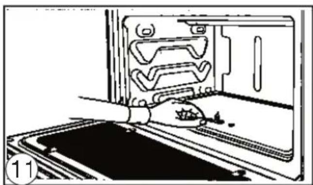
IGNITING THE OVEN BURNER
- Open the oven door;
- press the knob and turn it anti-clockwise to the maximum flame position
- move a burning match towards the hole in the centre of the oven bottom and press th knob right down (see fi g. 11)
- look through the two holes in the sides of the bottom to check that the burner has ignited, keeping the knob pressed down:
- after about 10 seconds, release the knob and check that the burner remains on.
GB
For the user
Otherwise, repeat the operation.
IGNITING THE GRILL BURNER
- Hit the control knob guard as shown in fig 13
- press the oven knob and turn it to the right until it reaches the stop
- move a burning match towards the perforated burner pipe and press the knob right down (see fig. 12)
- check that the burner has ignited, keeping the knob pressed down
- after about 10 seconds, release the knob and check that the burner remains on. Otherwise, repeat the operation.
SAFETY DEVICE
Burners equipped with this device have the advantage that they are protected if they acidentally go out. If this occurs, the supply gas to the burner concerned is automaticall cut off, preventing the hazards deriving from a leak of unburnt gas. The gas supply must be cut off within no more than 60 seconds for the oven and grill burners or 90 seconds for the hob burners.
FOR COOKERS WITH ELECTRIC IGNITION
All the above applies, except that the match is no longer required; a spark is obtained by pressing the button on the control panel once or more, or by pressing the knob of the burr to be ignited. If electronic ignition is difficult with some types of gas, set the knob on the low (small flame) setting
- For cookers with electric ignition of the oven and grill burners, ensure the oven door is completely open when these burners are ignited
- Do not operate the ignition device for more than 10 seconds when igniting the oven a grill burners. If the burner has not lit after these 10 seconds, stop using the device, leave the door open and wait one minute before trying again to ignite the burner. If the ignition device malfunctions again, light
the burner with a match and call the after-sales service.
IMPORTANT:
- Diffi culty in igniting burners is normal if the cooker has been out of use for some time. The air accumulated in the pipes will be expelled in a few seconds
- Never allow too much unburnt gas to flow from the burners. If ignition is not achieved within a relatively short time, repeat the procedure after returning the knob to the off position (●)
- when the oven and grill are lit for the first time, a smell may be noticed and smoke may come out of the oven. This is because of the surface treatment and oily residues on the burners.
HOW TO USE THE HOB BURNERS
Use pans of diameter suitable for the burne type. The flames must not project beyond t base of the pan. Recommended sizes:
- for auxiliary burners = pans of at least 8 cr using the adjusting grid supplied with the cooker
- for semi-rapid burners = pans of at least 1 cm
- for rapid and triple fl ame burners = pan of at least 22 cm
N.B.: Never keep the knob at settings between the maximum flame symbol and the off position (●).
- Never leave hotplates on without pans, except when fi rst used; leave for about 10 minutes to dry oil or moisture residues
- if the hotplate is to be out of use for a long time, apply a little grease to its paint surface:
- do not allow spills to burn onto the hotplate requiring the use of abrasive cleaners
- After igniting the burner, leave the oven to heat up for about 10 minutes
- place the food for cooking in an ordinary oven dish and place it on the chrome-plated shelf
GB
For the user
- place in the oven on the highest possible runners, and turn the knob pointer to the setting required
- cooking can be observed through the window in the door with the oven light on. This will avoid opening and closing the do frequently, unless oil or fat has to be added to the dish.
I he table below will serve as a guide.
IMPORTANT: never place foods directly on the drip tray for cooking; it is there only to collect any drips of fat during grilling.
N.B.: For cookers without thermostat
- with the knob on the maximum settin 🍻 = 280 degrees C.
- with the knob on the minimum setting ⏻ = 130 degrees C.
- All other temperatures between 130 and 280 degrees C. are obtained approximate by positioning the knob between the maximum and minimum settings.
Never leave the knob in positions between the maximum symbol 🍻 and the off setting (●).
| Dishes to be Thermostat Tempera-cooked knob ture in°C setting | |
| Meringues 1 160Biscuits 2 180Pasta bakes 3 200Cakes and fish | 4 215Roast pork or kid 5 230Hare and poultry 6 245Roast veal 7 260Pizza - roast beef 8 275 |
- tit the knob guard (see fig. 13)
- light the burner and wait a few minutes to give the burner time to warm up:
- place the foods on the chrome-plated shelf
- insert on the highest runner
- insert the drip tray on the bottom runner
- gently close the oven door, resting it against
the knob guard;
- after a few minutes, turn the food to expose the other side to the infrared radiation (the cooking time depends on the type of food and personal taste).
N.B.: the first time the grill is used smoke will come out of the oven. Before inserting foods for cooking, wait until any oil residues on the burner have completely burnt away. The grill must only be used at its full rated heat.
IMPORTANT : accessible parts may be hot when the grill is in use! Keep children well away. The table below will serve as a guide.
| Food to be grilled | Time (minutes) | |
| 1st side | 2nd side | |
| Thin pieces of meat | 6 | 4 |
| Fairly thick pieces of meat | 8 | 5 |
| Thin fish or fish without scale | 10 | 8 |
| Fairly thick fish 15 12 Sausages | 12 | 10 |
| Toasted sandwiches | 5 | 2 |
| Small poultry | 20 | 15 |
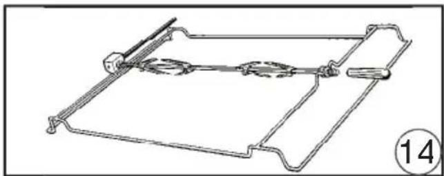
HOW TO USE THE ROTISSERIE
- fit the knob guard as shown in fig. 13
- impale the meat to be cooked on the spit and fix it in the centre using the two forks provided;
- insert the tip of the spit into the rotation hub on the frame (see fig. 14);
- take the handle off the spit;
- place the spit support frame in the central runner of the oven, at the same time inserting the rotation shaft into the motor hub (see fig. 15):
- place the drip tray on the bottom runner of the oven and pour a little water into it;
- light the grill burner;
- close the door gently, resting it on the kno guard;
- start the motor by pressing the switch on
GB
For the user
the control panel;
- baste the meat from time to time. When it is cooked, remove the frame from the mot hub and screw the handle back on to the spit.
CAUTION: The spit forks may have sharp points. Handle with care
OVEN LIGHT/ROTISSERIE SWITCH
- Gas cooker models are fitted with a round switch
- press this to turn on both the oven light and the rotisserie motor
- gas-electric cookers (1 or 2 electric plates are equipped with a round switch with a re pilot light
- this light comes on while 1 or 2 elec plates are in operation
OVENS WITH THERMOSTA1
If cooking temperatures are not as set, call an engineer to check the thermostat
FOR COOKERS WITH SELF-CLEANING OVEN
The two side walls and the back are coated with a catalytic self-cleaning enamel. Every 10-15 times it is used, leave the oven empt at full heat. The time required for cleaning depends on the condition of the oven. Som splashes tend to set hard and may clog the pores of the special coating, preventing oxidation and eliminating its self-cleaning properties. In this case, as soon as the oven has completely cooled apply very hot water to soften the deposits and use a soft brush, without detergent, to remove them. The switch the oven back on at maximum heat for a few minutes
(Important: never use metal brushes or abrasive substances)
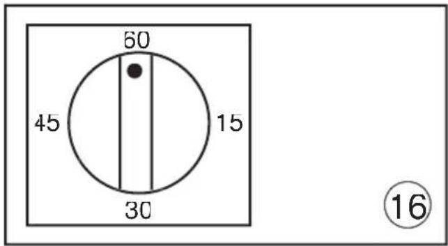
FOR COOKERS WITH MECHANICAL SPRING CLOCK (fi g.16
The spring clock can be set for a maximum time of one hour by turning the regulate knob clockwise to the time required. After
the pre-set time, a buzzer sounds and will stop automatically. When the buzzer sound the spring clock does not cut out operation of the oven
GENERAL PRECAUTIONS
- Always disconnect the power supply before any work inside the oven or where live part may be accessec
- Never use the warming compartment for storing intl ammable liquids or items which do not withstand heat, such as wood, pap aerosol cans, matches, et
- Make frequent checks on the rubber conn tion hose, ensuring that it is well away from hot surfaces, that there are no sharp bench or kinks, and that it is in good condition. Those must be replaced at the latest at the indicated date and must be secured at both ends using a standard hose clam
- It taps become stiff to operate over time, contact the After-Sales service
- Wash enamelled or chrome-plated parts with soapy lukewarm water or non-abrasiv detergents. A metal brush may be used to remove deposits from hob burners and fla caps. Dry thoroughly
- Never use abrasives to clean enamelled o chrome-plated parts
- Do not use too much water when washing the hob. I take care that no water or other substances enter the burner housing hole as this may be dangerous
- The spark plugs for electric ignition must be kept clean and dry; always check after use particularly if there have been drips or over flows from pan:
- Never close glass lids until the hob burner or hotplates have cooled completely; it might shatter or crack
- Never knock enamelled parts or ignition s1 plugs (where present
- The main or wall gas tap should be turned when the cooker is not in use
- Never knock enamelled parts or ignition sp plugs (where present
- The main or wall gas tap should be turned
GB
For the user
when the cooker is not in use
- Never lift the cooker by taking hold of tl oven door handle
- Any overheating of the outside walls of the oven will trip the safety device, which will off the power supply. The power supply will be restored automatically once the outside temperature of the oven has dropped back within acceptable limits. However, remember that if this device is tripped repeatedly, there is a malfunction (e.g. breakage of the ther stat which regulates the temperature inside the oven). Call in your service engine
- When the oven and grill are switched on to the first time there may be a typical smell and smoke may come out of the oven. This is because of the treatment applied to the surfaces. Operate the oven empty before placing foods inside
No liability is accepted for injury or damage caused by poor installation or improper use of the cooker
In case of malfunctions, particularly gas leaks or short-circuits, contact your eng neer without delay
EUROPEAN DIRECTIVE 2002/96/EC (WEEE): INFORMATION FOR THE CONSUMER
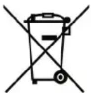
Fig. A
This information is strictly addressed to those who have a product showing the symbol below (Fig.A). This symbol is indicated on the technical data sticker (rating label) placed on the product itself.
This symbol indicates that the appliance is considered as Waste Electrical and Electronic Equipment and complies with the European directive 2002/96/EC (WEEE). Therefore this product is not to be treated a household waste. Instead it shall be handed over to the applicable collection point for the recycling of electrical and electronic equipment or it can be handed back to the retailer when you want to purchase a new equivale product. The consumer is responsible for a correct disposal of the product towards an appropriate collection point. Otherwise the consumer can be exposed to a penalty sanction by laws in force for waste disposal. Appropriate separate waste collection followed by recycling the product, the treatment and compatible environmental disposal contributes to avoid negative effects towards the environment and health and helps to recycle material which the product is composed of. For more detailed information regarding the available waste collection systems of the product please contact your local city office or contact the retailer where the product wa purchased. The manufacturers and importers will obey to their responsibility for recycling, treatment and compatible environmental disposal by participating directly and through a joint cooperative system
EUROPEAN REGULATION NO 1935/2004 – MATERIALS IN CONTACT WITH FOOD. NOTICE TO USERS.

The symbol shown here, which appears on the packaging, indicates that the materials in this product which may come into contact with food are compliant with the requirement of European Regulation No 1935/2004.
Inside the oven chamber, food might come into contact with oven shelves, dripping pans, pastry trays, oven door glazing, rubber gaskets, rotisserie spits, and the sides of the oven itself.
On the hob, contact is possible with pa stands, burners and the hob skin.
In the food-warmer, contact may occur with the sides of the compartment.
Index IntroductionFR
RECOMMANDATIONS IMPORTANTES:
natural_image
Technical line drawing of a mechanical device with an inset showing a close-up of its components (no text or symbols present)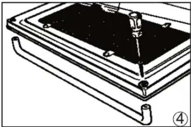
natural_image
Technical line drawing of a mechanical assembly with a tool inserted into a component (no text or symbols)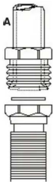
natural_image
Technical line drawing of a mechanical component with threaded ends and a cross-sectional view (no text or symbols)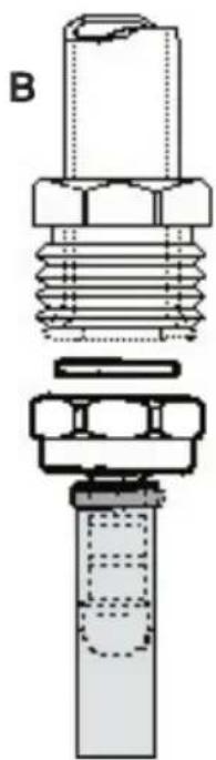
natural_image
Technical diagram of a mechanical component with threaded and flanged sections (no text or symbols)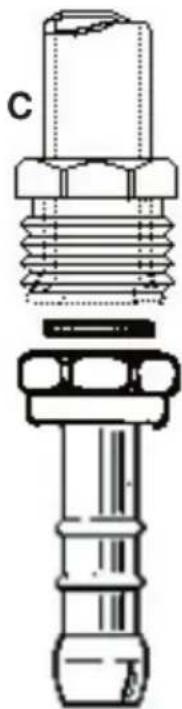
natural_image
Technical line drawing of a mechanical component with threaded ends and a flanged base (no text or symbols)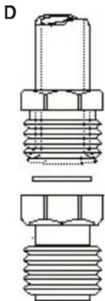
natural_image
Technical line drawing of a mechanical component with threaded ends and a flat base (no text or symbols)5
Figuras/ Figuras / Figures/Figures
natural_image
Technical line drawing of mechanical components labeled A and B, no readable text or symbols present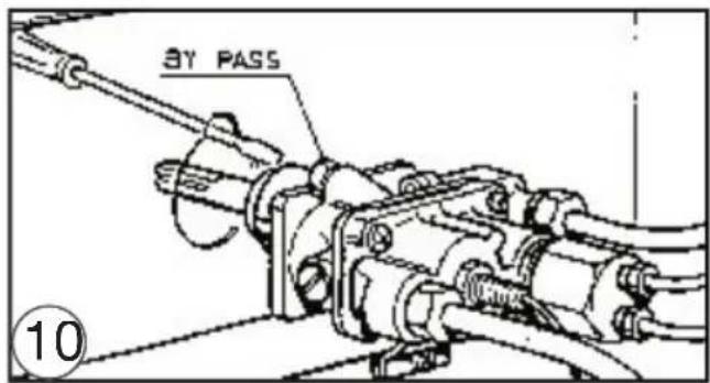
natural_image
Illustration of a hand operating a kitchen oven with a tray and control panel (no text or symbols visible)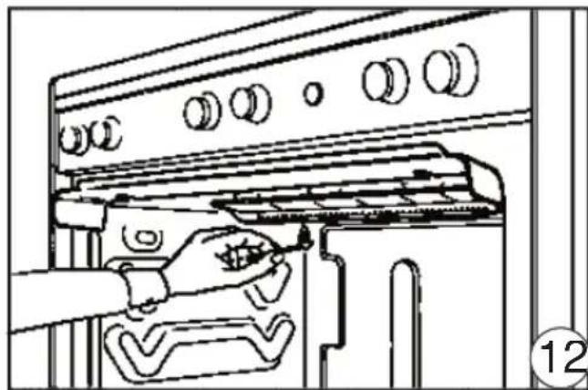
natural_image
Line drawing of a hand using a tool to adjust or install a kitchen appliance (no text or symbols present)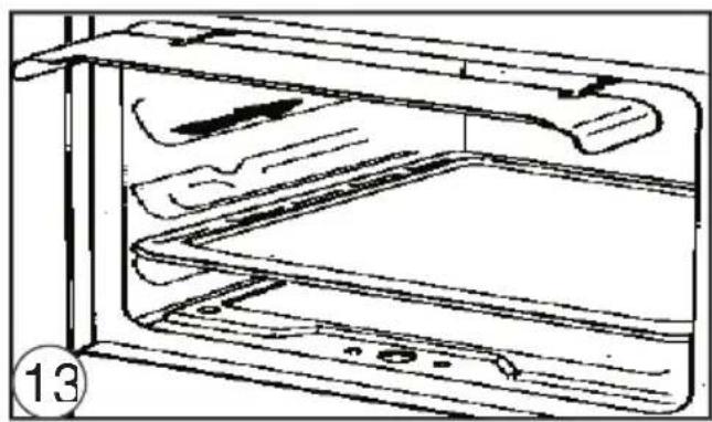
natural_image
Line drawing of a microwave oven with lid and tray (no text or symbols)Figuras/ Figuras / Figures/Figures
natural_image
Technical line drawing of a mechanical component with no visible text or symbols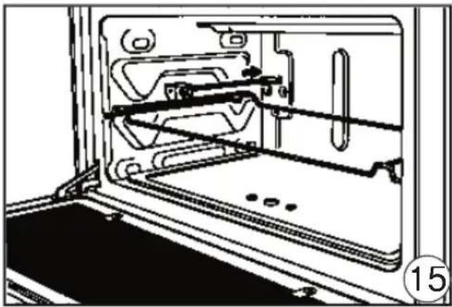
natural_image
Technical line drawing of a door frame with internal components and mounting base (no text or symbols)