X79 Extreme3 - Carte mère ASROCK - Free user manual and instructions
Find the device manual for free X79 Extreme3 ASROCK in PDF.
Download the instructions for your Carte mère in PDF format for free! Find your manual X79 Extreme3 - ASROCK and take your electronic device back in hand. On this page are published all the documents necessary for the use of your device. X79 Extreme3 by ASROCK.
USER MANUAL X79 Extreme3 ASROCK
No part of this installation guide may be reproduced, transcribed, transmitted, or trans-
lated in any language, in any form or by any means, except duplication of documentation
by the purchaser for backup purpose, without written consent of ASRock Inc.
Products and corporate names appearing in this guide may or may not be registered
trademarks or copyrights of their respective companies, and are used only for identica-
tion or explanation and to the owners’ benet, without intent to infringe.
Specications and information contained in this guide are furnished for informational use
only and subject to change without notice, and should not be constructed as a commit-
ment by ASRock. ASRock assumes no responsibility for any errors or omissions that may
appear in this guide.
With respect to the contents of this guide, ASRock does not provide warranty of any kind,
either expressed or implied, including but not limited to the implied warranties or condi-
tions of merchantability or tness for a particular purpose. In no event shall ASRock, its
directors, ofcers, employees, or agents be liable for any indirect, special, incidental, or
consequential damages (including damages for loss of prots, loss of business, loss of
data, interruption of business and the like), even if ASRock has been advised of the pos-
sibility of such damages arising from any defect or error in the guide or product.
This device complies with Part 15 of the FCC Rules. Operation is subject to the following
(1) this device may not cause harmful interference, and
(2) this device must accept any interference received, including interference that may
cause undesired operation.
CALIFORNIA, USA ONLY The Lithium battery adopted on this motherboard contains Perchlorate, a toxic substance
controlled in Perchlorate Best Management Practices (BMP) regulations passed by the
California Legislature. When you discard the Lithium battery in California, USA, please
follow the related regulations in advance.
“Perchlorate Material-special handling may apply, see
www.dtsc.ca.gov/hazardouswaste/perchlorate”
2013 ASRock INC. All rights reserved.2
RoHS PCI Express 3.0 Ready
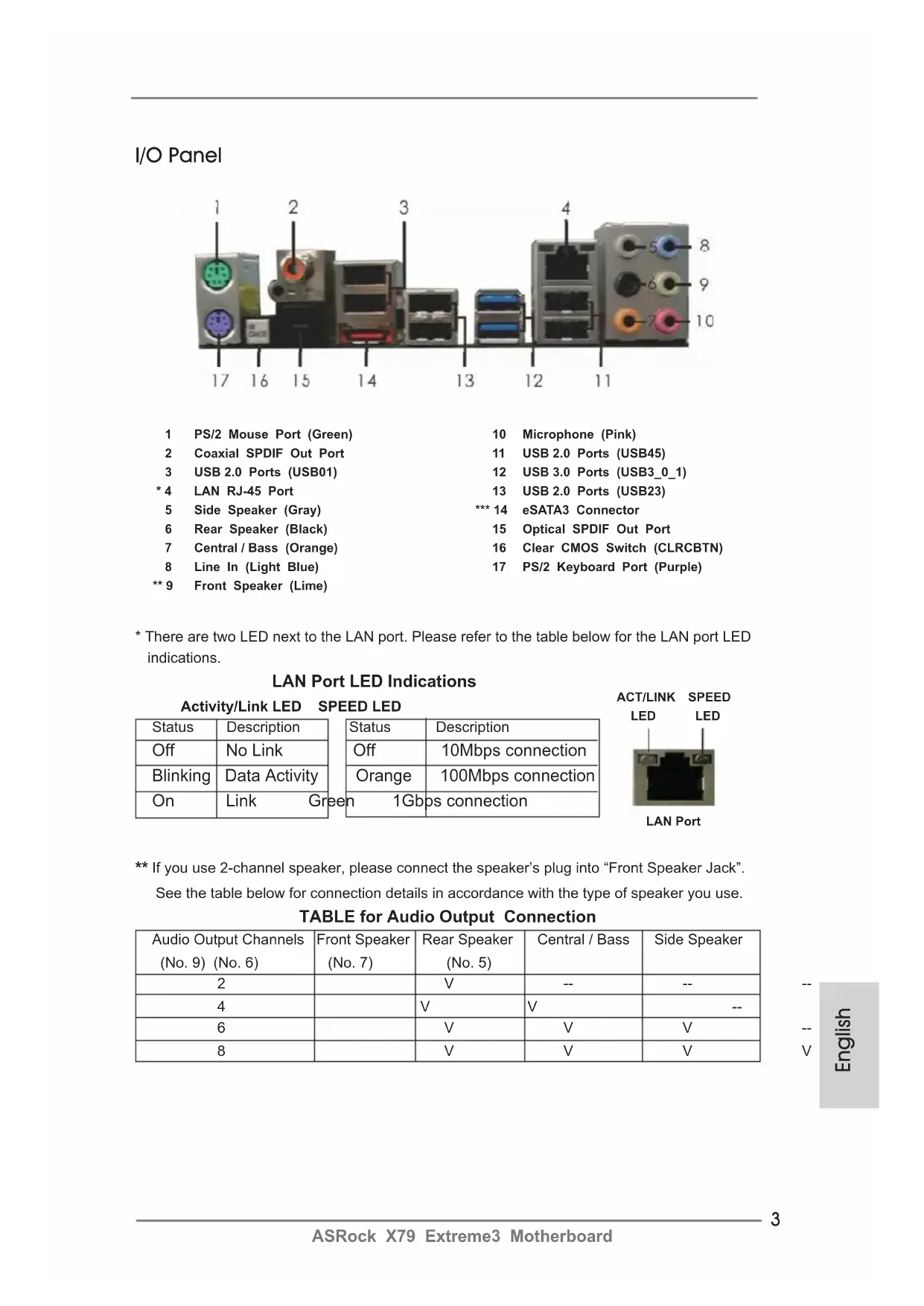
If you use 2-channel speaker, please connect the speaker’s plug into “Front Speaker Jack”.
See the table below for connection details in accordance with the type of speaker you use.
TABLE for Audio Output Connection
Audio Output Channels Front Speaker Rear Speaker Central / Bass Side Speaker
(No. 9) (No. 6) (No. 7) (No. 5)
* There are two LED next to the LAN port. Please refer to the table below for the LAN port LED
LAN Port LED Indications
Activity/Link LED SPEED LED Status Description Status Description
Off No Link Off 10Mbps connection
Blinking Data Activity Orange 100Mbps connection
1 PS/2 Mouse Port (Green) 10 Microphone (Pink)
** 9 Front Speaker (Lime)
ACT/LINK LED SPEED LED LAN Port4
ASRock X79 Extreme3 Motherboard
To enable Multi-Streaming function, you need to connect a front panel audio cable to the front
panel audio header. After restarting your computer, you will nd “Mixer” tool on your system.
Please select “Mixer ToolBox” , click “Enable playback multi-streaming”, and click
“ok”. Choose “2CH”, “4CH”, “6CH”, or “8CH” and then you are allowed to select “Realtek HDA Primary output” to use Rear Speaker, Central/Bass, and Front Speaker, or select “Realtek HDA Audio 2nd output” to use front panel audio.
Thank you for purchasing ASRock X79 Extreme3 motherboard, a reliable moth-
erboard produced under ASRock’s consistently stringent quality control. It delivers
excellent performance with robust design conforming to ASRock’s commitment to
quality and endurance.
This Quick Installation Guide contains introduction of the motherboard and step-by-
step installation guide. More detailed information of the motherboard can be found
in the user manual presented in the Support CD.
Because the motherboard specications and the BIOS software might be
updated, the content of this manual will be subject to change without no-
tice. In case any modications of this manual occur, the updated version
will be available on ASRock website without further notice. You may nd
the latest VGA cards and CPU support lists on ASRock website as well.
ASRock website http://www.asrock.com
If you require technical support related to this motherboard, please visit
our website for specic information about the model you are using.
www.asrock.com/support/index.asp
1.1 Package Contents
(ATX Form Factor: 12.0-in x 8.8-in, 30.5 cm x 22.4 cm)
ASRock X79 Extreme3 Support CD
1 x I/O Panel Shield
1 x ASRock SLI_Bridge_2S Card
1 x ASRock 3-Way SLI-2S1S Bridge Card
ASRock Reminds You...
To get better performance in Windows
bit, it is recommended to set the BIOS option in Storage Conguration to
AHCI mode. For the BIOS setup, please refer to the “User Manual” in our
support CD for details.6
ASRock X79 Extreme3 Motherboard
Platform - ATX Form Factor: 12.0-in x 8.8-in, 30.5 cm x 22.4 cm
- Premium Gold Capacitor design (100% Japan-made high-
quality Conductive Polymer Capacitors)
CPU - Supports Intel
i7 processor family for the LGA 2011
Turbo Boost 2.0 Technology
- Supports Hyper-Threading Technology (see CAUTION 1)
- Supports Untied Overclocking Technology
- Supports DDR3 2400+(OC)/2133(OC)/1866(OC)/1600/1333/
1066 non-ECC, un-buffered memory
- Supports DDR3 ECC, un-buffered memory with Intel
- Max. capacity of system memory: 32GB (see CAUTION 3)
- Supports Wake-On-LAN
- Supports Energy Efcient Ethernet 802.3az
- Supports PXE Rear Panel I/O I/O Panel
- 1 x PS/2 Mouse Port
- 2 x Ready-to-Use USB 3.0 Ports
- 1 x RJ-45 LAN Port with LED (ACT/LINK LED and SPEED LED)
- 1 x Clear CMOS Switch with LED
- HD Audio Jack: Side Speaker/Rear Speaker/Central/Bass/
Line in/Front Speaker/Microphone (see CAUTION 5)
SATA3 - 2 x SATA3 6.0 Gb/s connectors by Intel
(RAID 0, RAID 1, RAID 5, RAID 10 and Intel Rapid
Storage3.0), NCQ, AHCI and "Hot Plug" functions
- 1 x SATA3 6.0 Gb/s connector by ASMedia ASM1061,
supports NCQ, AHCI and "Hot Plug" functions
USB3.0 - 2 x Rear USB 3.0 ports by Etron EJ168A, support
USB 1.0/2.0/3.0 up to 5Gb/s
- 1 x Front USB 3.0 header (supports 2 USB 3.0 ports) by
Etron EJ168A, supports USB 1.0/2.0/3.0 up to 5Gb/s
Connector - 4 x SATA2 3.0 Gb/s connectors, support RAID (RAID 0,
RAID 1, RAID 5, RAID 10 and Intel Rapid Storage3.0),
NCQ, AHCI and Hot Plug functions
- 1 x Power LED header
- CPU/Chassis/Power/SB FAN connector
- 24 pin ATX power connector
- 8 pin 12V power connector
- SLI/XFire power connector
- Front panel audio connector
- 3 x USB 2.0 headers (support 6 USB 2.0 ports)
- 1 x USB 3.0 header (supports 2 USB 3.0 ports)
Smart Switch - 1 x Clear CMOS Switch with LED BIOS Feature - 64Mb AMI UEFI Legal BIOS with GUI support
- Supports “Plug and Play”
- ACPI 1.1 Compliance Wake Up Events
- Supports jumperfree
- SMBIOS 2.3.1 Support8
ASRock X79 Extreme3 Motherboard
- CPU, VCCSA, DRAM, VTT, CPU PLL, PCH1.1V, PCH1.5V Voltage Multi-adjustment
Support CD - Drivers, Utilities, AntiVirus Software (Trial Version),
CyberLink MediaEspresso 6.5 Trial
Unique Feature - ASRock Extreme Tuning Utility (AXTU) (see CAUTION 6)
- ASRock Instant Boot
- ASRock Instant Flash (see CAUTION 7)
- ASRock APP Charger (see CAUTION 8)
- CPU Frequency Stepless Control (see CAUTION 15)
- ASRock U-COP (see CAUTION 16)
- Boot Failure Guard (B.F.G.)
- Good Night LED Hardware - CPU Temperature Sensing
Monitor - Chassis Temperature Sensing
- CPU/Chassis/Power/SB Fan Tachometer
- CPU/Chassis Quiet Fan (Allows Chassis Fan Speed Auto-
Adjust by CPU Temperature)
- CPU/Chassis/SB Fan Multi-Speed Control
- Voltage Monitoring: +12V, +5V, +3.3V, CPU Vcore
/ XP / XP 64-bit compliant (see CAUTION 17)
Certications - FCC, CE, WHQL
- ErP/EuP Ready (ErP/EuP ready power supply is required)
* For detailed product information, please visit our website: http://www.asrock.com9
ASRock X79 Extreme3 Motherboard
WARNING Please realize that there is a certain risk involved with overclocking, including
adjusting the setting in the BIOS, applying Untied Overclocking Technology, or using
third-party overclocking tools. Overclocking may affect your system’s stability, or
even cause damage to the components and devices of your system. It should be
done at your own risk and expense. We are not responsible for possible damage
caused by overclocking.
1. About the setting of “Hyper Threading Technology”, please check page
55 of the User Manual in the support CD.
2. This motherboard supports Quad Channel Memory Technology. Before
you implement Quad Channel Memory Technology, make sure to read
the installation guide of memory modules on page 16 for proper installa-
3. Due to the operating system limitation, the actual memory size may be
less than 4GB for the reservation for system usage under Windows
OS with 64-bit CPU, there is no such limita-
tion. You can use ASRock XFast RAM to utilize the memory that Win-
Socket 2011 Sandy Bridge-E Processor doesn’t support
PCIE 3.0, but this motherboard is already PCIE 3.0 hardware ready. It
depends on Intel’s CPU to enable PCIE 3.0. Please check Intel’s website
for information on future CPU updates and releases.
5. For microphone input, this motherboard supports both stereo and mono
modes. For audio output, this motherboard supports 2-channel, 4-chan-
nel, 6-channel, and 8-channel modes. Please check the table on page 3
for proper connection.
6. ASRock Extreme Tuning Utility (AXTU) is an all-in-one tool to ne-tune dif-
ferent system functions in a user-friendly interface, which includes Hard-
ware Monitor, Fan Control, Overclocking, OC DNA and IES. In Hardware
Monitor, it shows the major readings of your system. In Fan Control, it
shows the fan speed and temperature for you to adjust. In Overclocking,
you are allowed to overclock CPU frequency for optimal system per-
formance. In OC DNA, you can save your OC settings as a prole and
share it with your friends. Your friends then can load the OC prole to
their own system to get the same OC settings. In IES (Intelligent Energy
Saver), the voltage regulator can reduce the number of output phases to
improve efciency when the CPU cores are idle without sacricing com-
puting performance. Please visit our website for the operation procedures
of ASRock Extreme Tuning Utility (AXTU).
ASRock website: http://www.asrock.com
7. ASRock Instant Flash is a BIOS ash utility embedded in Flash ROM.
This convenient BIOS update tool allows you to update system BIOS
without entering operating systems rst like MS-DOS or Windows
to enter into the BIOS setup menu to access ASRock Instant Flash.
Just launch this tool and save the new BIOS le to your USB ash drive,
oppy disk or hard drive, then you can update your BIOS only in a few
clicks without preparing an additional oppy diskette or other complicated
ash utility. Please be noted that the USB ash drive or hard drive must
use FAT32/16/12 le system.
8. If you desire a faster, less restricted way of charging your Apple devices,
such as iPhone/iPad/iPod Touch, ASRock has prepared a wonderful solu-
tion for you - ASRock APP Charger. Simply install the APP Charger
driver, it makes your iPhone charge much quickly from your computer and
up to 40% faster than before. ASRock APP Charger allows you to quickly
charge many Apple devices simultaneously and even supports continu-
ous charging when your PC enters into Standby mode (S1), Suspend to
RAM (S3), hibernation mode (S4) or power off (S5). With APP Charger
driver installed, you can easily enjoy the marvelous charging experience.
ASRock website: http://www.asrock.com/Feature/AppCharger/index.asp
9. ASRock XFast USB can boost USB storage device performance. The
performance may depend on the properties of the device.
10. ASRock XFast LAN provides a faster internet access, which includes
the benets listed below. LAN Application Prioritization: You can cong-
ure your application’s priority ideally and/or add new programs. Lower
Latency in Game: After setting online game’s priority higher, it can lower
the latency in games. Trafc Shaping: You can watch Youtube HD videos
and download simultaneously. Real-Time Analysis of Your Data: With
the status window, you can easily recognize which data streams you are
transferring currently.
11. ASRock XFast Charger is the best and fastest technology to charge your
mobile devices via PC. With the superb XFast Charger USB port, users
are assured to enjoy the quick charging experience anytime. In addi-
tion to Apple devices, it is also capable of Charging the BC 1.1 standard
smart devices. Please refer to page 33 for details.
12. ASRock XFast RAM is a new function that is included into ASRock Ex-
treme Tuning Utility (AXTU). It fully utilizes the memory space that cannot
be used under Windows
OS 32-bit CPU. ASRock XFast RAM shortens
the loading time of previously visited websites, making web surng faster
than ever. And it also boosts the speed of Adobe Photoshop 5 times
faster. Another advantage of ASRock XFast RAM is that it reduces the11
ASRock X79 Extreme3 Motherboard
frequency of accessing your SSDs or HDDs in order to extend their lifes-
13. ASRock X-FAN will be automatically activated only when the system rises
to a certain temperature under heavy-loading or overclocking. Normally,
ASRock X-FAN will remain deactivated to give users the quietest comput-
ing experience. The target temperature and fan speed settings can be
congured in the UEFI setup utility.
14. ASRock Crashless BIOS allows users to update their BIOS without fear
of failing. If power loss occurs during the BIOS update process, ASRock
Crashless BIOS will automatically nish the BIOS update procedure after
regaining power. Please note that BIOS les need to be placed in the root
directory of your USB disk. Only USB2.0 ports support this feature.
15. Although this motherboard offers stepless control, it is not recommended
to perform over-clocking. Frequencies other than the recommended CPU
bus frequencies may cause instability of the system or damage the CPU.
16. While CPU overheat is detected, the system will automatically shutdown.
Before you resume the system, please check if the CPU fan on the moth-
erboard functions properly and unplug the power cord, then plug it back
again. To improve heat dissipation, remember to spray thermal grease
between the CPU and the heatsink when you install the PC system.
17. Intel Rapid Storage Technology enterprise 3.0 and ASRock XFast RAM
are not supported by
18. EuP stands for Energy Using Product, was a provision regulated by the
European Union to define the power consumption for the completed
system. According to EuP, the total AC power of the completed system
should be under 1.00W in off mode condition. To meet EuP standards,
an EuP ready motherboard and an EuP ready power supply are required.
According to Intel’s suggestion, the EuP ready power supply must meet
the standard of 5v, and the standby power efciency should be higher
than 50% under 100 mA current consumption. For EuP ready power sup-
ply selection, we recommend you to check with the power supply manu-
facturer for more details.12
ASRock X79 Extreme3 Motherboard
Pre-installation Precautions
Take note of the following precautions before you install mother-
board components or change any motherboard settings.
1. Unplug the power cord from the wall socket before touching any
component. Failure to do so may cause severe damage to the
motherboard, peripherals, and/or components.
2. To avoid damaging the motherboard components due to static
electricity, NEVER place your motherboard directly on the car-
pet or the like. Also remember to use a grounded wrist strap or
touch a safety grounded object before you handle components.
3. Hold components by the edges and do not touch the ICs.
4. Whenever you uninstall any component, place it on a grounded
antstatic pad or in the bag that comes with the component.
5. When placing screws into the screw holes to secure the moth-
erboard to the chassis, please do not over-tighten the screws!
Doing so may damage the motherboard.
2.1 CPU Installation
For the installation of Intel 2011-Pin CPU,
please follow the steps below.
Before you insert the 2011-Pin CPU into the socket, please check if the
CPU surface is unclean or if there are any bent pins in the socket. Do
not force to insert the CPU into the socket if above situation is found.
Otherwise, the CPU will be seriously damaged.
2011-Pin Socket Overview
Step 1. Open the socket:
Step 1-1. Disengage the left lever by pressing it
down and sliding it out of the hook.
Step 1-2. Disengage the right lever by pressing
it down and sliding it out of the hook.
Step 1-3. Keep the right lever positioned at
about 90 degrees in order to ip up
Step 2. Insert the 2011-Pin CPU:
Step 2-1. Hold the CPU by the edge with the
triangle mark(Pin 1) on your upper
Step 2-2. Locate Pin1 and the two orientation
For proper inserting, please ensure to match the four orientation key
notches of the CPU with the four alignment keys of the socket.
Step 2-3. Carefully place the CPU into the
socket by using a purely vertical mo-
Step 2-4. Verify that the CPU is within the sock-
et and properly mated to the orient
Step 3. Close the socket:
Step 3-1. Flip the load plate onto the IHS, then
the cover will automatically come off
The cover must be placed if returning the
motherboard for after service.
Step 3-2. Press down the right load lever, and
secure it with the load plate tab under
Step 3-3. Press down the left load lever, and
secure it with the load plate tab under
ASRock X79 Extreme3 Motherboard
2.2 Installation of CPU Fan and Heatsink
This motherboard is equipped with 2011-Pin socket that supports Intel 2011-Pin
CPU. Please adopt the type of heatsink and cooling fan compliant with Intel 2011-
Pin CPU to dissipate heat. Before you installed the heatsink, you need to spray
thermal interface material between the CPU and the heatsink to improve heat dis-
sipation. Ensure that the CPU and the heatsink are securely fastened and in good
contact with each other. Then connect the CPU fan to the CPU_FAN connector
(CPU_FAN1, see page 2, No. 6).
For proper installation, please kindly refer to the instruction manuals of your
CPU fan and heatsink.
Below is an example to illustrate the installation of the heatsink for 2011-Pin CPU.
Step 1. Apply thermal interface material onto center of
IHS on the socket surface.
Step 2. Place the heatsink onto the socket. Ensure
fan cables are oriented on side closest to the
CPU fan connector on the motherboard (CPU_
FAN1, see page 2, No. 6).
Step 3. Align screws with the motherboard’s holes.
Step 4. Use a screw driver to install the screws.
If you don’t fasten the screws, the heatsink cannot be secured on
Step 5. Connect fan header with the CPU fan connector on the motherboard.
Step 6. Secure excess cable with tie-wrap to ensure the cable does not interfere
with fan operation or contact other components.16
ASRock X79 Extreme3 Motherboard
2.3 Installation of Memory Modules (DIMM)
This motherboard provides four 240-pin DDR3 (Double Data Rate 3) DIMM
slots, and supports Quad Channel Memory Technology. For quad channel con-
guration, you always need to install identical (the same brand, speed, size
and chip-type) DDR3 DIMM in the slots: You have to install identical DDR3
DIMM in DDR3_A1, DDR3_B1, DDR3_D1 and DDR3_C1 (Black slots; see p.2
No.2 and No. 5), so that Quad Channel Memory Technology can be activated.
1. If only two memory modules are installed in the DDR3 DIMM slots,
then Dual Channel Memory Technology is activated. If three memo-
ry modules are installed, then Triple Channel Memory Technology is
activated. If four memory modules are installed in the DDR3 DIMM
slots, then Quad Channel Memory Technology is activated.
2. It is not allowed to install a DDR or DDR2 memory module into
DDR3 slot; otherwise, this motherboard and DIMM may be dam-
Installing a DIMM Please make sure to disconnect power supply before adding or
removing DIMMs or the system components.
Step 1. Unlock a DIMM slot by pressing the retaining clips outward.
Step 2. Align a DIMM on the slot such that the notch on the DIMM matches the
The DIMM only ts in one correct orientation. It will cause permanent
damage to the motherboard and the DIMM if you force the DIMM into
the slot at incorrect orientation.
Step 3. Firmly insert the DIMM into the slot until the retaining clips at both ends
fully snap back in place and the DIMM is properly seated.17
ASRock X79 Extreme3 Motherboard
2.4 Expansion Slots (PCI and PCI Express Slots)
There are 2 PCI slots and 4 PCI Express slots on this motherboard.
PCI slots: PCI slots are used to install expansion cards that have the 32-bit PCI
PCIE slots: PCIE1 / PCIE3 (PCIE 3.0 x16 slots) are used for PCI Express x16 lane
width graphics cards, or used to install PCI Express graphics cards to
PCIE2 (PCIE 2.0 x1 slot) is used for a PCI Express x1 lane width card,
such as Gigabit LAN card or SATA2 card, etc.
PCIE4 (PCIE 3.0 x16 slot) is used to install a PCI Express graphics card
to support 3-Way CrossFireX TM
function or to install an AS-
Rock Game Blaster card.
1. In single VGA card mode, it is recommended to install a PCI Express
x16 graphics card on PCIE1 slot.
mode, please install PCI Express x16
graphics cards on PCIE1 and PCIE3 slots. Therefore, both these two
slots will work at x16 bandwidth.
3. In 3-Way CrossFireX TM
mode, please install PCI Express x16 graphics cards on PCIE1, PCIE3 and PCIE4 slots.
Therefore, both PCIE1 and PCIE3 will work at x16 bandwidth, while
PCIE4 works at x8 bandwidth.
4. Please connect a chassis fan to motherboard chassis fan connector
(CHA_FAN1, CHA_FAN2 or CHA_FAN3) when using multiple
graphics cards for better thermal environment.
Socket 2011 Sandy Bridge-E Processor doesn’t
support PCIE 3.0, but this motherboard is already PCIE 3.0 hardware
ready. It depends on Intel’s CPU to enable PCIE 3.0. Please check
Intel’s website for information on future CPU updates and releases.
Installing an expansion card
Step 1. Before installing the expansion card, please make sure that the power
supply is switched off or the power cord is unplugged. Please read the
documentation of the expansion card and make necessary hardware
settings for the card before you start the installation.
Step 2. Remove the system unit cover (if your motherboard is already installed
Step 3. Remove the bracket facing the slot that you intend to use. Keep the
screws for later use.
Step 4. Align the card connector with the slot and press rmly until the card is
completely seated on the slot.
Step 5. Fasten the card to the chassis with screws.
Step 6. Replace the system cover.18
This motherboard supports NVIDIA
Link Interface) technology that allows you to install up to three identical PCI Express
x16 graphics cards. Currently, NVIDIA
technology supports Windows
technology support Windows
64-bit / 7 / 7 64-bit OS only.
Please follow the installation procedures in this section.
technology, you should have two identical SLI TM
cards that are NVIDIA
certied. For 3-Way SLI TM
technology, you should
have three identical 3-Way SLI TM
-ready graphics cards that are NVIDIA
certied. For Quad SLI TM
technology, you should have two identical Quad
-ready graphics cards that are NVIDIA
2. Make sure that your graphics card driver supports NVIDIA
(driver version 280.41 and later). Download the driver from NVIDIA website
3. Make sure that your power supply unit (PSU) can provide at least the
minimum power required by your system. It is recommended to use NVIDIA
certied PSU. Please refer to NVIDIA
website for details.
-ready graphics cards that are NVIDIA
because different types of graphics cards will not work together properly.
(Even the GPU chips version shall be the same.) Insert one graphics card
into PCIE1 slot and the other graphics card to PCIE3 slot. Make sure that
the cards are properly seated on the slots.
Step2. If required, connect the auxiliary power source to the PCI Express graph-
connector of the graphics card that is inserted to PCIE1 slot.
Step3. Align and insert the ASRock SLI_Bridge_2S Card to the goldngers on
each graphics card. Make sure the ASRock SLI_Bridge_2S Card is rmly
-ready graphics cards that are NVIDIA
certied because different types of graphics cards will not work together
properly. (Even the GPU chips version shall be the same.) Each graph-
ics card should have two goldngers for the 3-Way SLI Bridge connector.
Insert one graphics card into PCIE1 slot, another graphics card to PCIE3
slot, and the other graphics card to PCIE4 slot. Make sure that the cards
are properly seated on the slots.
Step2. Connect the auxiliary power source to the PCI Express graphics card.
Please make sure that both power connectors on the PCI Express graph-
ics card are connected. Repeat this step on the three graphics cards.
Step4. Connect a VGA cable or a DVI cable to the monitor connector or the DVI
connector of the graphics card that is inserted to PCIE1 slot.
Step3. Align and insert ASRock 3-Way SLI-2S1S Bridge Card to the goldngers
on each graphics card. Make sure ASRock 3-Way SLI-2S1S Bridge Card
2.5.2 Driver Installation and Setup
Install the graphics card drivers to your system. After that, you can enable the Multi-
Graphics Processing Unit (GPU) feature in the NVIDIA
nView system tray utility.
Please follow the below procedures to enable the multi-GPU feature.
B. From the pop-up menu, select Set SLI and PhysX conguration. In
Set PhysX GPU acceleration item, please select Enabled. In Select
an SLI conguration item, please select Enable SLI. And click Apply.
C. Reboot your system.
D. You can freely enjoy the benet of SLI TM
B. From the pop-up menu, select All Programs, and then click NVIDIA Corporation.
C. Select NVIDIA Control Panel tab.
D. Select Control Panel tab.
E. From the pop-up menu, select Set SLI and PhysX conguration. In
Set PhysX GPU acceleration item, please select Enabled. In Select
an SLI conguration item, please select Enable SLI. And click Apply.
F. Reboot your system.
G. You can freely enjoy the benet of SLI TM
A. Follow step A to D on page 22.
B. From the pop-up menu, select Set SLI and PhysX conguration. In
Select a hardware acceleration setting for PhysX item, please select
Enabled. In Select an SLI conguration item, please select Enable
3-way SLI. And click Apply.
C. Reboot your system.
D. You can freely enjoy the benet of 3-Way SLI TM
appearing here is a registered trademark of NVIDIA
Technologies Inc., and is used
only for identication or explanation and to the owners’ benet, without intent to infringe.24
ASRock X79 Extreme3 Motherboard
1. If a customer incorrectly congures their system they will not see the performance
benets of CrossFireX TM
. All three CrossFireX TM
components, a CrossFireX TM Ready graphics card, a CrossFireX TM Ready motherboard and a CrossFireX TM Edition co-processor graphics card, must be installed correctly to benet from the
2. If you pair a 12-pipe CrossFireX TM Edition card with a 16-pipe card, both cards
will operate as 12-pipe cards while in CrossFireX TM
This motherboard supports CrossFireX TM
feature. CrossFireX TM
technology offers the most advantageous
means available of combining multiple high performance Graphics Processing
Units (GPU) in a single PC. Combining a range of different operating modes with
intelligent software design and an innovative interconnect mechanism, CrossFireX TM
enables the highest possible level of performance and image quality in any 3D
application. Currently CrossFireX TM
feature is supported with Windows
are supported with Windows
/ 7 OS only. Please check AMD website for
Different CrossFireX TM
cards may require different methods to enable CrossFireX TM
feature. In below procedures, we use Radeon HD 5770 as the example graphics
card. For other CrossFireX TM
cards that AMD has released or will release in the
future, please refer to AMD graphics card manuals for detailed installation guide.
Step 1. Insert one Radeon graphics card into PCIE1 slot and the other Radeon
graphics card to PCIE3 slot. Make sure that the cards are properly seated
Step 3. Connect the DVI monitor cable to the DVI connector on the Radeon
graphics card on PCIE1 slot. (You may use the DVI to D-Sub adapter to
convert the DVI connector to D-Sub interface, and then connect the D-Sub
monitor cable to the DVI to D-Sub adapter.)
Step 2. Connect two Radeon graphics cards by installing CrossFire Bridge on
CrossFire Bridge Interconnects on the top of Radeon graphics cards.
(CrossFire Bridge is provided with the graphics card you purchase, not
bundled with this motherboard. Please refer to your graphics card vendor
-ready graphics cards that are
certified because different types of graphics cards will not work
together properly. (Even the GPU chips version shall be the same.) Insert
one graphics card into PCIE1 slot, another graphics card to PCIE3 slot,
and the other graphics card to PCIE4 slot. Make sure that the cards are
properly seated on the slots.
Step 4. Use one CrossFire
TM Bridge to connect Radeon graphics cards on PCIE1
and PCIE3 slots, and use the other CrossFire
TM Bridge to connect Radeon
graphics cards on PCIE3 and PCIE4 slots. (CrossFire
TM Bridge is provided
with the graphics card you purchase, not bundled with this motherboard.
Please refer to your graphics card vendor for details.)
Step 5. Connect the DVI monitor cable to the DVI connector on the Radeon graph-
ics card on PCIE1 slot. (You may use the DVI to D-Sub adapter to convert
the DVI connector to D-Sub interface, and then connect the D-Sub monitor
cable to the DVI to D-Sub adapter.)27
ASRock X79 Extreme3 Motherboard
The Catalyst Uninstaller is an optional download. We recommend using this utility to
uninstall any previously installed Catalyst drivers prior to installation.
Please check AMD website for ATI TM
Step 3. Install the required drivers to your system.
XP Service Pack 2 or higher to be
installed (If you have Windows
XP Service Pack 2 or higher installed
in your system, there is no need to download it again):
http://www.microsoft.com/windowsxp/sp2/default.mspx
B. You must have Microsoft .NET Framework installed prior to
downloading and installing the CATALYST Control Center. Please
check Microsoft website for details.
Install the CATALYST Control Center. Please check AMD website for
Step 4. Restart your computer.
Step 5. Install the VGA card drivers to your system, and restart your computer.
Then you will nd “ATI Catalyst Control Center” on your Windows
ATI Catalyst Control Center
2.6.2 Driver Installation and Setup
Step 1. Power on your computer and boot into OS.
Step 2. Remove the AMD driver if you have any VGA driver installed in your
Step 6. Double-click “ATI Catalyst Control Center”. Click “View”, select “CrossFi-
”, and then check the item “Enable CrossFireX TM
and click “Apply” (if you install two Radeon graphics cards). Select “3
GPUs” and click “OK” (if you install three Radeon graphics cards).28
ASRock X79 Extreme3 Motherboard
2.7 Surround Display Feature
This motherboard supports Surround Display upgrade. With the external add-on PCI Express VGA cards, you can easily enjoy the benets of Surround Display feature.
For the detailed instruction, please refer to the document at the following path in the
..\ Surround Display Information
Although you have selected the option “Enable CrossFire
”, the CrossFireX TM
function may not work actually. Your computer will automatically reboot. After
in “ATI Catalyst Control Center” is selected or not; if not, please select it again, and
then you are able to enjoy the benet of CrossFireX TM
appearing here is a registered trademark of AMD Technologies Inc., and is
used only for identication or explanation and to the owners’ benet, without intent to infringe.
* For further information of AMD CrossFireX TM
technology, please check AMD website for
ASRock X79 Extreme3 Motherboard
* ASRock Smart Remote is only supported by some of ASRock motherboards. Please refer to
ASRock website for the motherboard support list: http://www.asrock.com
USB 2.0 header (9-pin, black)
CIR header (4-pin, gray)
2.8 ASRock Smart Remote Installation Guide
ASRock Smart Remote is only used for ASRock motherboard with CIR header.
Please refer to below procedures for the quick installation and usage of ASRock
Step1. Find the CIR header located next
to the USB 2.0 header on ASRock
Step2. Connect the front USB cable to the
USB 2.0 header (as below, pin 1-5)
and the CIR header. Please make
sure the wire assignments and the
pin assignments are matched
the front USB port. If Multi-Angle
CIR Receiver cannot successfully
receive the infrared signals from
MCE Remote Controller, please try
to install it to the other front USB
3 CIR sensors in different angles
1. Only one of the front USB port can support CIR function. When
the CIR function is enabled, the other port will remain USB
2. Multi-Angle CIR Receiver is used for front USB only. Please do
not use the rear USB bracket to connect it on the rear panel.
Multi-Angle CIR Receiver can receive the multi-direction infrared
signals (top, down and front), which is compatible with most of
the chassis on the market.
3. The Multi-Angle CIR Receiver does not support Hot-Plug
function. Please install it before you boot the system.30
ASRock X79 Extreme3 Motherboard
2.9 ASRock XFast Charger Operation Guide
ASRock XFast Charger is the best and
fastest technology to charge your mobile
devices via PC. With the superb XFast
Charger USB port, users are assured to
enjoy the quick charging experience
anytime. In addition to Apple devices, it
is also capable of Charging the BC 1.1
standard smart devices. Please refer to
below instruction for proper operation.
This motherboard provides two USB ports for ASRock XFast Charger:
1. USB 2.0 port (USB0) on the I/O panel
2. USB 2.0 port (USB6) header
With ASRock XFast Charger feature, you can freely enjoy the quick charging
convenience by installing the USB cable on these two ports.
The illustration shows how jumpers are
setup. When the jumper cap is placed on
pins, the jumper is “Short”. If no jumper cap
is placed on pins, the jumper is “Open”. The
illustration shows a 3-pin jumper whose
pin1 and pin2 are “Short” when jumper cap
is placed on these 2 pins.
Jumper Setting Description
Note: CLRCMOS1 allows you to clear the data in CMOS. To clear and reset the sys-
tem parameters to default setup, please turn off the computer and unplug the
power cord from the power supply. After waiting for 15 seconds, use a jumper
cap to short pin2 and pin3 on CLRCMOS1 for 5 seconds. However, please do
not clear the CMOS right after you update the BIOS. If you need to clear the
CMOS when you just nish updating the BIOS, you must boot up the system
rst, and then shut it down before you do the clear-CMOS action. Please be
noted that the password, date, time, user default prole, 1394 GUID and MAC
address will be cleared only if the CMOS battery is removed.
The Clear CMOS Switch has the same function as the Clear CMOS
ASRock X79 Extreme3 Motherboard
2.11 Onboard Headers and Connectors
Onboard headers and connectors are NOT jumpers. Do NOT place
jumper caps over these headers and connectors. Placing jumper caps
over the headers and connectors will cause permanent damage of the
Serial ATA2 Connectors These four Serial ATA2 (SATA2)
(SATA2_0_1: see p.2, No. 16)
connectors support SATA data
(SATA2_2_3: see p.2, No. 17)
cables for internal storage
devices. The current SATA2
interface allows up to 3.0 Gb/s
Serial ATA3 Connectors These three Serial ATA3
(SATA3_A0: see p.2, No. 11)
(SATA3) connectors support
(SATA3_0_1: see p.2, No. 15)
SATA data cables for internal
storage devices. The current
SATA3 interface allows up to
6.0 Gb/s data transfer rate.
Data Cable cable can be connected to the
SATA / SATA2 / SATA3 hard
connector on this motherboard.
USB 2.0 Headers Besides six default USB 2.0
ports on the I/O panel, there
are three USB 2.0 headers on
this motherboard. Each USB 2.0
header can support two USB
Front Panel Audio Header This is an interface for front
panel audio cable that allows
convenient connection and
control of audio devices.
and receiving infrared module.
USB 3.0 Header Besides two default USB 3.0
ports on the I/O panel, there is
one USB 3.0 header on this
motherboard. This USB 3.0
header can support two USB
controller receiver.
1. High Denition Audio supports Jack Sensing, but the panel wire on the
chassis must support HDA to function correctly. Please follow the
instruction in our manual and chassis manual to install your system.
2. If you use AC’97 audio panel, please install it to the front panel audio
A. Connect Mic_IN (MIC) to MIC2_L.
B. Connect Audio_R (RIN) to OUT2_R and Audio_L (LIN) to OUT2_L.
C. Connect Ground (GND) to Ground (GND).
D. MIC_RET and OUT_RET are for HD audio panel only. You don’t need
to connect them for AC’97 audio panel.34
ASRock X79 Extreme3 Motherboard
E. To activate the front mic.
Go to the "FrontMic" Tab in the Realtek Control panel. Adjust
System Panel Header This header accommodates
several system front panel
Connect the power switch, reset switch and system status indicator on the
chassis to this header according to the pin assignments below. Note the
positive and negative pins before connecting the cables.
PWRBTN (Power Switch):
Connect to the power switch on the chassis front panel. You may congure
the way to turn off your system using the power switch.
RESET (Reset Switch):
Connect to the reset switch on the chassis front panel. Press the reset
switch to restart the computer if the computer freezes and fails to perform a
PLED (System Power LED):
Connect to the power status indicator on the chassis front panel. The LED
is on when the system is operating. The LED keeps blinking when the sys-
tem is in S1 sleep state. The LED is off when the system is in S3/S4 sleep
state or powered off (S5).
HDLED (Hard Drive Activity LED):
Connect to the hard drive activity LED on the chassis front panel. The LED
is on when the hard drive is reading or writing data.
The front panel design may differ by chassis. A front panel module mainly
consists of power switch, reset switch, power LED, hard drive activity LED,
speaker and etc. When connecting your chassis front panel module to this
header, make sure the wire assignments and the pin assign-ments are
Chassis Speaker Header Please connect the chassis
speaker to this header.
ASRock X79 Extreme3 Motherboard
Power LED Header Please connect the chassis
power LED to this header to
indicate system power status.
The LED is on when the system
is operating. The LED keeps
blinking in S1 state. The LED is
off in S3/S4 state or S5 state
Chassis, Power and SB Fan Connectors Please connect the fan cables
to the fan connectors and
match the black wire to the
ground pin. CHA_FAN1,
CHA_FAN2 and CHA_FAN3
support Fan Control. SB_FAN1
CPU Fan Connectors Please connect the CPU fan
cable to the connector and
match the black wire to the
Though this motherboard provides 4-Pin CPU fan (Quiet Fan) support, the 3-Pin
CPU fan still can work successfully even without the fan speed control function. If
you plan to connect the 3-Pin CPU fan to the CPU fan connector on this
motherboard, please connect it to Pin 1-3.
3-Pin Fan Installation
ATX Power Connector Please connect an ATX power
supply to this connector.
20-Pin ATX Power Supply Installation
Though this motherboard provides 24-pin ATX power connector,
it can still work if you adopt a traditional 20-pin ATX power supply.
To use the 20-pin ATX power supply, please plug your
power supply along with Pin 1 and Pin 13.
ATX 12V Power Connector Please connect an ATX 12V
power supply to this connector.
4-Pin ATX 12V Power Supply Installation
Though this motherboard provides 8-pin ATX 12V power connector, it can still work
if you adopt a traditional 4-pin ATX 12V power supply. To use the 4-pin ATX power
supply, please plug your power supply along with Pin 1 and Pin 5. 5 18 45 18 4 SLI/XFIRE Power Connector It is not necessary to use this
(4-pin SLI/XFIRE_PWR1)
connector, but please connect it
with a hard disk power
connecor when two graphics
cards are plugged to this
VGA card, allows the system to
connect HDMI Digital TV/
projector/LCD devices. Please
connect the HDMI_SPDIF
connector of HDMI VGA card to
The motherboard has a smart switch: Clear CMOS switch.
Clear CMOS Switch Clear CMOS Switch is a smart
switch, allowing users to quickly
2.13 Driver Installation Guide
To install the drivers to your system, please insert the support CD to your optical
drive rst. Then, the drivers compatible to your system can be auto-detected and
listed on the support CD driver page. Please follow the order from up to bottom side
to install those required drivers. Therefore, the drivers you install can work properly.
2.14 Installing Windows
If you want to install Windows
/ SATA2 / SATA3 HDDs with RAID functions, please refer to the document at the
following path in the Support CD for detailed procedures:
..\ RAID Installation Guide
If you want to install Windows
64-bit / XP / XP 64-
bit OS on your SATA / SATA2 / SATA3 HDDs without RAID functions, please follow
below procedures according to the OS you install.
2.15.1 Installing Windows
If you want to install Windows
XP / XP 64-bit OS on your SATA / SATA2 / SATA3
HDDs without RAID functions, please follow below steps.
STEP 1: Set Up UEFI.
B. Set the option “SATA Mode” to [IDE]. (For SATA2_0 to SATA2_3, SATA3_0 and
If you want to install Windows
64-bit OS on your SATA
/ SATA2 / SATA3 HDDs without RAID functions, please follow below steps.
Using SATA / SATA2 / SATA3 HDDs with NCQ function
2.16 Untied Overclocking Technology
This motherboard supports Untied Overclocking Technology, which means during
overclocking, FSB enjoys better margin due to xed PCI / PCIE buses. Before you
enable Untied Overclocking function, please enter “Overclock Mode” option of UEFI
setup to set the selection from [Auto] to [Manual]. Therefore, CPU FSB is untied
during overclocking, but PCI / PCIE buses are in the xed mode so that FSB can
operate under a more stable overclocking environment.
Please refer to the warning on page 9 for the possible overclocking risk
before you apply Untied Overclocking Technology.
STEP 1: Set Up UEFI.
A. Enter UEFI SETUP UTILITY Advanced screen Storage Conguration.
B. Set the option “SATA Mode” to [AHCI]. (For SATA2_0 to SATA2_3, SATA3_0 and
Set the option “ASMedia SATA3 Operation Mode” to [AHCI]. (For SATA3_A0
B. Set the option “SATA Mode” to [IDE]. (For SATA2_0 to SATA2_3, SATA3_0 and
The Flash Memory on the motherboard stores BIOS Setup Utility. When you start up
the computer, please press <F2> or <Del> during the Power-On-Self-Test (POST)
to enter BIOS Setup utility; otherwise, POST continues with its test routines. If you
wish to enter BIOS Setup after POST, please restart the system by pressing <Ctl>
+ <Alt> + <Delete>, or pressing the reset button on the system chassis. The BIOS Setup program is designed to be user-friendly. It is a menu-driven program, which
allows you to scroll through its various sub-menus and to select among the prede-
termined choices. For the detailed information about BIOS Setup, please refer to the
User Manual (PDF le) contained in the Support CD.
4. Software Support CD information
This motherboard supports various Microsoft
operating systems: 7 / 7
64-bit / XP / XP 64-bit. The Support CD that came with the
motherboard contains necessary drivers and useful utilities that will enhance moth-
erboard features. To begin using the Support CD, insert the CD into your CD-ROM
drive. It will display the Main Menu automatically if “AUTORUN” is enabled in your
computer. If the Main Menu does not appear automatically, locate and double-click
on the le “ASSETUP.EXE” from the BIN folder in the Support CD to display the
E/A-Anschlüsse I/O Panel
(CLRCMOS1, 3-Pin jumper)
- Gestion jumperless
Certications - FCC, CE, WHQL
charge 2 ports USB 2.0.
(ATX Form Factor: 12.0-in x 8.8-in, 30.5 cm x 22.4 cm)
- Supporta Wake-On-LAN
- Supporta “Plug and Play”
- Compatibile con ACPI 1.1 wake up events
- Supporta jumperfree
- Boot Failure Guard (B.F.G.)
Sito ASRock: http://www.asrock.com/Feature/AppCharger/index.asp
- Soporta “Plug and Play”
- ACPI 1.1 compliance wake up events
- Soporta “jumper free”
- Soporta SMBIOS 2.3.1
Sertikalar - FCC, CE, WHQL
64-bit CPU'lu Windows
ASRock internet sitesi: http://www.asrock.com/Feature/AppCharger/index.
(CLRCMOS1, 3-pinli jumper)
SATA2 arayüzü 3,0 Gb/sn veri
SATA3 arayüzü 6,0 Gb/sn veri
- ACPI 1.1 Compliance Wake Up Events
OS to be installed on a
large size HDD (>2TB). Please follow the procedures below to install the operating
1. Please make sure to use Windows
64-bit (with SP1 or above) or
2. Press <F2> or <Delete> at system POST. Set AHCI Mode in UEFI Setup Utility >
Advanced > Storage Conguration > SATA Mode.
3. Choose the item “UEFI:xxx“ to boot in UEFI Setup Utility > Boot > Boot Option #1.
(“xxx” is the device which contains your Windows
installation les. Normally it is
an optical drive.) You can also press <F11> to launch boot menu at system POST
and choose the item “UEFI:xxx“ to boot.
OS to be installed on a
large size HDD (>2TB). Please follow the procedures below to install the operating
1. Please make sure to use Windows
64-bit (with SP1 or above) or
RAID drivers into a USB ash disk. You can download the driver from
ASRock's website and unzip the le into a USB ash disk OR copy the le from
ASRock motherboard support CD. (please copy the les under the following
32 bit: ..\i386\Win7_Vista_Intel_v3.0.0.1112
64-bit: ..\AMD64\Win7-64_Vista64_Intel_v3.0.0.1112
3. Create a RAID array for you system. Please refer to "Intel RAID Installation
Guide" le for details.
64-bit / 7 64-bit installation disc to the optical
B. Press <F11> to launch boot menu at system POST and choose the item
Installation. When you see “Where do you want to install
Windows?” page, please click “Load Driver”.
D. Plug the USB ash disk into your USB port; select “Browse” to nd the RAID
driver. Then choose the directory (xx\AMD64\) you have copied in the rst
64-bit in a large hard disk (ex. Disk
volume > 2TB), it may take more time to boot into Windows
utilities. If you encounter this problem, you will need to following instructions
does not provide hotx for this problem. The steps listed below
's suggested solution:
a. Type “systempropertiesprotection” in the Start Menu. Then press
b. De-select Local Disks for System Restore. Then Click “Turn System
Restore Off” to conrm. Then Press “Ok”.
E. Please keep the USB ash disk installed until the system rst reboot.
F. Continue to install OS by following the Windows
B. Disable “Volume Shadow Copy” service.
a. Type “computer management” in the Start Menu, then press “Enter”.
b. Go to “Services and Applications>Services”; Then double click “Volume
c. Set “Startup type” to “Disable” then Click “OK”.
C. Reboot your system.
D. After reboot, please start to install motherboard drivers and utilities.
A. Please request the hotx KB2505454 through this link:
B. After installing Windows
7 64-bit, install the hotx kb2505454.
(This may take a long time; >30 mins.)
C. Reboot your system. (It may take about 5 minutes to reboot.)
will install this hotx then reboot by itself.
E. Please start to install motherboard drivers and utilities.