N68VGS3 FX - Carte mère ASROCK - Free user manual and instructions
Find the device manual for free N68VGS3 FX ASROCK in PDF.
Download the instructions for your Carte mère in PDF format for free! Find your manual N68VGS3 FX - ASROCK and take your electronic device back in hand. On this page are published all the documents necessary for the use of your device. N68VGS3 FX by ASROCK.
USER MANUAL N68VGS3 FX ASROCK
No part of this installation guide may be reproduced, transcribed, transmitted, or trans-
lated in any language, in any form or by any means, except duplication of documen-
tation by the purchaser for backup purpose, without written consent of ASRock Inc.
Products and corporate names appearing in this guide may or may not be registered
trademarks or copyrights of their respective companies, and are used only for identifica-
tion or explanation and to the owners’ benefit, without intent to infringe.
Disclaimer:Disclaimer:
Disclaimer:Disclaimer:
Specifications and information contained in this guide are furnished for informational
use only and subject to change without notice, and should not be constructed as a
commitment by ASRock. ASRock assumes no responsibility for any errors or omissions
that may appear in this guide.
With respect to the contents of this guide, ASRock does not provide warranty of any kind,
either expressed or implied, including but not limited to the implied warranties or
conditions of merchantability or fitness for a particular purpose. In no event shall
ASRock, its directors, officers, employees, or agents be liable for any indirect, special,
incidental, or consequential damages (including damages for loss of profits, loss of
business, loss of data, interruption of business and the like), even if ASRock has been
advised of the possibility of such damages arising from any defect or error in the guide
This device complies with Part 15 of the FCC Rules. Operation is subject to the
following two conditions:
(1) this device may not cause harmful interference, and
(2) this device must accept any interference received, including interference that
may cause undesired operation.
Published December 2011
Copyright©2011 ASRock INC. All rights reserved.
CALIFORNIA, USA ONLY The Lithium battery adopted on this motherboard contains Perchlorate, a toxic
substance controlled in Perchlorate Best Management Practices (BMP) regulations
passed by the California Legislature. When you discard the Lithium battery in
California, USA, please follow the related regulations in advance.
“Perchlorate Material-special handling may apply, see
www.dtsc.ca.gov/hazardouswaste/perchlorate”
(Dual Channel: DDR3_A1, DDR3_B1; Blue) 18 Print Port Header (LPT1, White)
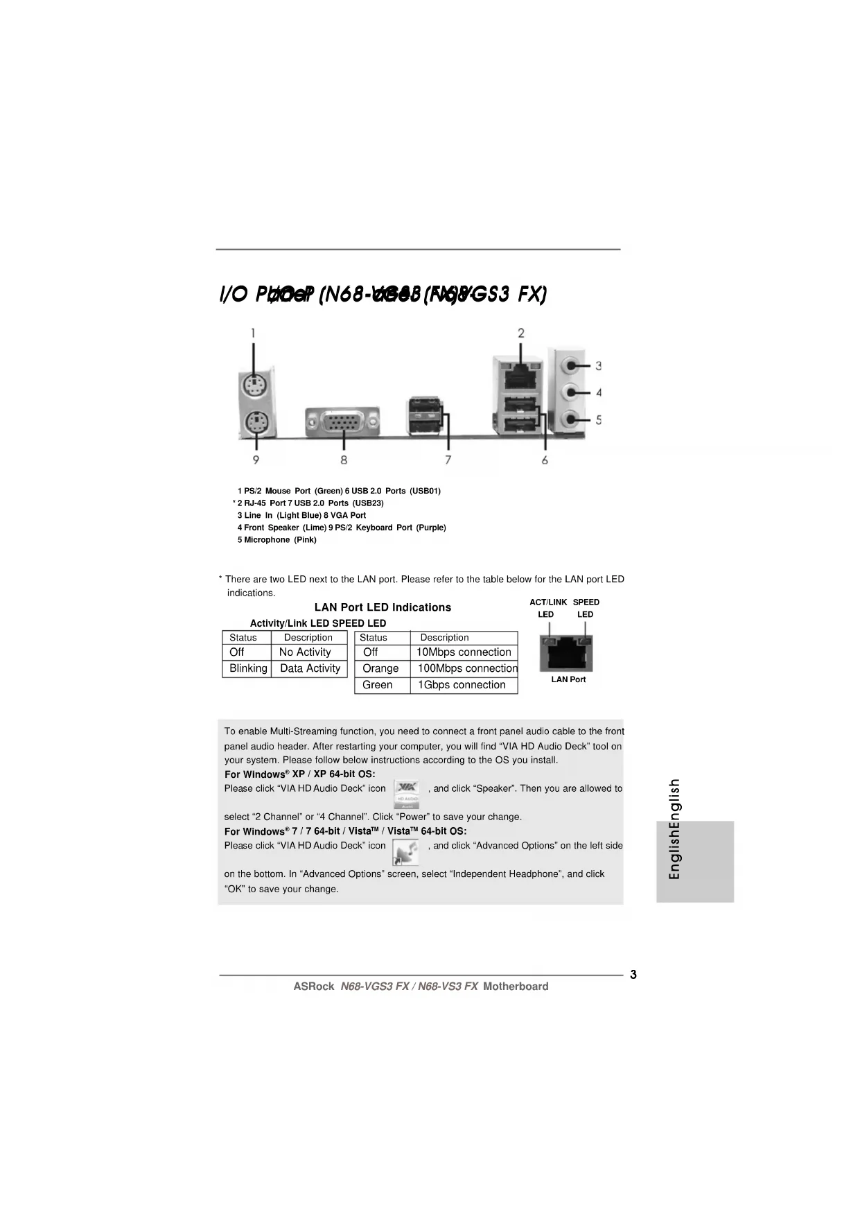
I/O PI/O P I/O PI/O P I/O P
anel (N68-anel (N68-
anel (N68-anel (N68-
* There are two LED next to the LAN port. Please refer to the table below for the LAN port LED
LAN Port LED Indications
Activity/Link LED SPEED LED Status Description Status Description
Off No Activity Off 10Mbps connection
Blinking Data Activity Orange 100Mbps connection
Green 1Gbps connection LAN PortACT/LINK LEDSPEED LED To enable Multi-Streaming function, you need to connect a front panel audio cable to the front
panel audio header. After restarting your computer, you will find “VIA HD Audio Deck” tool on
your system. Please follow below instructions according to the OS you install.
Please click “VIA HD Audio Deck” icon , and click “Speaker”. Then you are allowed to
select “2 Channel” or “4 Channel”. Click “Power” to save your change.
on the bottom. In “Advanced Options” screen, select “Independent Headphone”, and click
I/O PI/O P I/O PI/O P I/O P
anel (N68-anel (N68-
anel (N68-anel (N68-
* There are two LED next to the LAN port. Please refer to the table below for the LAN port LED
LAN Port LED Indications
Activity/Link LED SPEED LED Status Description Status Description
Off No Activity Off 10Mbps connection
Blinking Data Activity Orange 100Mbps connection LAN PortACT/LINK LEDSPEED LED To enable Multi-Streaming function, you need to connect a front panel audio cable to the front
panel audio header. After restarting your computer, you will find “VIA HD Audio Deck” tool on
your system. Please follow below instructions according to the OS you install.
Please click “VIA HD Audio Deck” icon , and click “Speaker”. Then you are allowed to
select “2 Channel” or “4 Channel”. Click “Power” to save your change.
on the bottom. In “Advanced Options” screen, select “Independent Headphone”, and click
Thank you for purchasing ASRock N68-VGS3 FX / N68-VS3 FX motherboard, a reliable
motherboard produced under ASRock’s consistently stringent quality control. It delivers
excellent performance with robust design conforming to ASRock’s commitment to qual-
In this manual, chapter 1 and 2 contain introduction of the motherboard and step-by-step
guide to the hardware installation. Chapter 3 and 4 contain the configuration guide to
BIOS setup and information of the Support CD. Because the motherboard specifications and the BIOS software mightbe updated, the content of this manual will be subject to change withoutnotice. In case any modifications of this manual occur, the updatedversion will be available on ASRock website without further notice. Youmay find the latest VGA cards and CPU support lists on ASRock websiteas well. ASRock website http://www.asrock.comIf you require technical support related to this motherboard, please visitour website for specific information about the model you are using.www.asrock.com/support/index.asp 1.11.1
(Micro ATX Form Factor: 8.5-in x 7.0-in, 21.6 cm x 17.8 cm)
One ASRock N68-VGS3 FX / N68-VS3 FX Quick Installation Guide
One ASRock N68-VGS3 FX / N68-VS3 FX Support CD Two Serial ATA (SATA) Data Cables (Optional)
One I/O Panel Shield66
Platform - Micro ATX Form Factor: 8.5-in x 7.0-in, 21.6 cm x 17.8 cm
CPU - Support for Socket AM3+ processors
- Support for AM3 processors: AMD Phenom
TM II X6 / X4 / X3 /
X2 (except 920 / 940) / Athlon II X4 / X3 / X2 / Sempron
processors (see CAUTION 1)
- Supports 8-Core CPU
- Supports UCC feature (Unlock CPU Core) (see CAUTION 2)
- Supports AMD’s Cool ‘n’ Quiet
- FSB 1000 MHz (2.0 GT/s)
- Supports Untied Overclocking Technology (see CAUTION 3)
- Supports Hyper-Transport Technology
Memory - Dual Channel DDR3 Memory Technology (see CAUTION 4)
- 2 x DDR3 DIMM slots
- Support DDR3 1600/1333/1066/800 non-ECC, un-buffered
memory (see CAUTION 5)
- Max. capacity of system memory: 16GB (see CAUTION 6)
Expansion Slot - 1 x PCI Express x16 slot
Graphics - Integrated NVIDIA
- Supports D-Sub with max. resolution up to 1920x1440
- N68-VS3 FX Realtek PHY RTL8201EL, speed 10/100 Mb/s
- Supports Wake-On-LAN
- Supports PXE Rear Panel I/O I/O Panel
- 1 x PS/2 Mouse Port
- 4 x Ready-to-Use USB 2.0 Ports
- 1 x RJ-45 LAN Port with LED (ACT/LINK LED and SPEED LED)
- HD Audio Jack: Line in / Front Speaker / Microphone77
Connector - 4 x SATA2 3.0Gb/s connectors, support RAID (RAID 0, RAID 1,
- 1 x COM port header
- CPU/Chassis FAN connector
- 24 pin ATX power connector
- 4 pin 12V power connector
- Supports “Plug and Play”
- ACPI 1.1 Compliance Wake Up Events
- Supports jumperfree
- SMBIOS 2.3.1 Support
- CPU, VCCM Voltage Multi-adjustment
Support CD - Drivers, Utilities, AntiVirus Software (Trial Version), CyberLink
MediaEspresso 6.5 Trial, ASRock Software Suite (CyberLink
DVD Suite - OEM and Trial; Creative Sound Blaster X-Fi MB -
- CPU Frequency Stepless Control (see CAUTION 17)
- ASRock U-COP (see CAUTION 18)
- Boot Failure Guard (B.F.G.)
WARNING Please realize that there is a certain risk involved with overclocking, including
adjusting the setting in the BIOS, applying Untied Overclocking Technology, or using
the third-party overclocking tools. Overclocking may affect your system stability, or
even cause damage to the components and devices of your system. It should be
done at your own risk and expense. We are not responsible for possible damage
caused by overclocking.
1. This motherboard supports CPU up to 95W. Please refer to our website for
CPU support list. ASRock website
http://www.asrock.com
2. ASRock UCC (Unlock CPU Core) feature simplifies AMD CPU activation. As
long as a simple switch of the BIOS option “ASRock UCC”, you can unlock
the extra CPU core to enjoy an instant performance boost. When UCC
feature is enabled, the dual-core or triple-core CPU will boost to the quad-
core CPU, and some CPU, including quad-core CPU, can also increase L3
cache size up to 6MB, which means you can enjoy the upgrade CPU perfor-
mance with a better price. Please be noted that UCC feature is supported
with AM3/AM3+ CPU only, and in addition, not every AM3/AM3+ CPU can
support this function because some CPU’s hidden core may be
3. This motherboard supports Untied Overclocking Technology. Please read
“Untied Overclocking Technology” on page 21 for details.
4. This motherboard supports Dual Channel Memory Technology. Before
you implement Dual Channel Memory Technology, make sure to read
the installation guide of memory modules on page 13 for proper
5. Whether 1600MHz memory speed is supported depends on the AM3/
AM3+ CPU you adopt. If you want to adopt DDR3 1600 memory module
on this motherboard, please refer to the memory support list on our
website for the compatible memory modules.
ASRock website http://www.asrock.com
6. Due to the operating system limitation, the actual memory size may be
less than 4GB for the reservation for system usage under Windows
OS with 64-bit CPU, there is no such
7. The maximum shared memory size is defined by the chipset vendor
and is subject to change. Please check NVIDIA
website for the latest
/ XP / XP 64-bit compliant
Certifications - FCC, CE, WHQL
* For detailed product information, please visit our website:
http://www.asrock.com99
8. Before installing SATAII hard disk to SATAII connector, please read the “SATAII Hard Disk Setup Guide” on page 24 of “User Manual” in the support CD to
adjust your SATAII hard disk drive to SATAII mode. You can also connect
SATA hard disk to SATAII connector
9. It is a user-friendly ASRock overclocking tool which allows you to surveil
your system by hardware monitor function and overclock your hardware
devices to get the best system performance under Windows
environment. Please visit our website for the operation procedures of
ASRock OC Tuner. ASRock website:
http://www.asrock.com
10. Featuring an advanced proprietary hardware and software design,
Intelligent Energy Saver is a revolutionary technology that delivers
unparalleled power savings. The voltage regulator can reduce the
number of output phases to improve efficiency when the CPU cores are
idle. In other words, it is able to provide exceptional power saving and
improve power efficiency without sacrificing computing performance.
To use Intelligent Energy Saver function, please enable Cool ‘n’ Quiet
option in the BIOS setup in advance. Please visit our website for the
operation procedures of Intelligent Energy Saver.
ASRock website: http://www.asrock.com
11. ASRock Instant Flash is a BIOS flash utility embedded in Flash ROM.
This convenient BIOS update tool allows you to update system BIOS
without entering operating systems first like MS-DOS or Windows
With this utility, you can press <F6> key during the POST or press <F2>
key to BIOS setup menu to access ASRock Instant Flash. Just launch
this tool and save the new BIOS file to your USB flash drive, floppy disk
or hard drive, then you can update your BIOS only in a few clicks without
preparing an additional floppy diskette or other complicated flash utility.
Please be noted that the USB flash drive or hard drive must use FAT32/
12. The software name itself – OC DNA literally tells you what it is capable
of. OC DNA, an exclusive utility developed by ASRock, provides a conve-
nient way for the user to record the OC settings and share with others.
It helps you to save your overclocking record under the operating sys-
tem and simplifies the complicated recording process of overclocking
settings. With OC DNA, you can save your OC settings as a profile and
share with your friends! Your friends then can load the OC profile to their
own system to get the same OC settings as yours! Please be noticed
that the OC profile can only be shared and worked on the same
13. If you desire a faster, less restricted way of charging your Apple devices,
such as iPhone/iPod/iPad Touch, ASRock has prepared a wonderful
solution for you - ASRock APP Charger. Simply installing the APP Charger
driver, it makes your iPhone charged much quickly from your computer
and up to 40% faster than before. ASRock APP Charger allows you to
quickly charge many Apple devices simultaneously and even supports
continuous charging when your PC enters into Standby mode (S1),
Suspend to RAM (S3), hibernation mode (S4) or power off (S5). With
APP Charger driver installed, you can easily enjoy the marvelous charg-
ing experience than ever.
ASRock website: http://www.asrock.com/Feature/AppCharger/index.asp
14. SmartView, a new function of internet browser, is the smart start page
for IE that combines your most visited web sites, your history, your
Facebook friends and your real-time newsfeed into an enhanced view
for a more personal Internet experience. ASRock motherboards are
exclusively equipped with the SmartView utility that helps you keep in
touch with friends on-the-go. To use SmartView feature, please make
sure your OS version is Windows
and your browser version is IE8.
ASRock website: http://www.asrock.com/Feature/SmartView/index.asp
15. ASRock XFast USB can boost USB storage device performance. The
performance may depend on the property of the device.
16. ASRock XFast LAN provides a faster internet access, which includes
below benefits. LAN Application Prioritization: You can configure your
application priority ideally and/or add new programs. Lower Latency in
Game: After setting online game priority higher, it can lower the latency
in game. Traffic Shaping: You can watch Youtube HD video and down-
load files simultaneously. Real-Time Analysis of Your Data: With the
status window, you can easily recognize which data streams you are
currently transferring.
17. Although this motherboard offers stepless control, it is not recom-
mended to perform over-clocking. Frequencies other than the recom-
mended CPU bus frequencies may cause the instability of the system
18. While CPU overheat is detected, the system will automatically shutdown.
Before you resume the system, please check if the CPU fan on the
motherboard functions properly and unplug the power cord, then plug it
back again. To improve heat dissipation, remember to spray thermal
grease between the CPU and the heatsink when you install the PC
This is a Micro ATX form factor (8.5-in x 7.0-in, 21.6 cm x 17.8 cm) motherboard.
Before you install the motherboard, study the configuration of your chassis to en-
sure that the motherboard fits into it.
Pre-installation PrecautionsPre-installation Precautions
Pre-installation PrecautionsPre-installation Precautions
Pre-installation Precautions
Take note of the following precautions before you install motherboard
components or change any motherboard settings. Before you install or remove any component, ensure that thepower is switched off or the power cord is detached from thepower supply. Failure to do so may cause severe damage to themotherboard, peripherals, and/or components. 1. Unplug the power cord from the wall socket before touching any
2. To avoid damaging the motherboard components due to static
electricity, NEVER place your motherboard directly on the carpet or
the like. Also remember to use a grounded wrist strap or touch a
safety grounded object before you handle components.
3. Hold components by the edges and do not touch the ICs.
4. Whenever you uninstall any component, place it on a grounded anti-
static pad or in the bag that comes with the component.
5. When placing screws into the screw holes to secure the motherboard
to the chassis, please do not over-tighten the screws! Doing so may
damage the motherboard.
Step 1. Unlock the socket by lifting the lever up to a 90
Step 2. Position the CPU directly above the socket such that the CPU corner with
the golden triangle matches the socket corner with a small triangle.
Step 3. Carefully insert the CPU into the socket until it fits in place.
The CPU fits only in one correct orientation. DO NOT force the CPU
into the socket to avoid bending of the pins.
Step 4. When the CPU is in place, press it firmly on the socket while you push
down the socket lever to secure the CPU. The lever clicks on the side tab
to indicate that it is locked.
Installation of CPU Fan and HeatsinkInstallation of CPU Fan and Heatsink
Installation of CPU Fan and HeatsinkInstallation of CPU Fan and Heatsink
Installation of CPU Fan and Heatsink
After you install the CPU into this motherboard, it is necessary to install a
larger heatsink and cooling fan to dissipate heat. You also need to spray
thermal grease between the CPU and the heatsink to improve heat
dissipation. Make sure that the CPU and the heatsink are securely fas-
tened and in good contact with each other. Then connect the CPU fan to
the CPU FAN connector (CPU_FAN1, see Page 2, No. 2). For proper
installation, please kindly refer to the instruction manuals of the CPU fan
and the heatsink. STEP 1:Lift Up The Socket LeverSTEP 2 / STEP 3:Match The CPU Golden TriangleTo The Socket Corner SmallTriangleSTEP 4:Push Down And LockThe Socket LeverLever 90° UpCPU Golden TriangleSocker Corner Small Triangle1313
2.3 Installation of Memor2.3 Installation of Memor
2.3 Installation of Memor2.3 Installation of Memor
2.3 Installation of Memor
N68-VGS3 FX / N68-VS3 FX motherboard provides two 240-pin DDR3 (Double Data
Rate 3) DIMM slots, and supports Dual Channel Memory Technology. For dual channel
configuration, you always need to install two identical (the same brand, speed, size and
chip-type) memory modules in the DDR3 DIMM slots to activate Dual Channel Memory
Technology. Otherwise, it will operate at single channel mode.
1. It is not allowed to install a DDR or DDR2 memory module into
DDR3 slot;otherwise, this motherboard and DIMM may be damaged.
2. If you install only one memory module or two non-identical memory
modules, it is unable to activate the Dual Channel Memory Technology.
Installing a DIMMInstalling a DIMM Installing a DIMMInstalling a DIMM Installing a DIMM Please make sure to disconnect power supply before adding or
removing DIMMs or the system components.
Step 1. Unlock a DIMM slot by pressing the retaining clips outward.
Step 2. Align a DIMM on the slot such that the notch on the DIMM matches the break
The DIMM only fits in one correct orientation. It will cause permanent
damage to the motherboard and the DIMM if you force the DIMM into the
slot at incorrect orientation.
Step 3. Firmly insert the DIMM into the slot until the retaining clips at both ends fully
snap back in place and the DIMM is properly seated.1414
2.4 Expansion Slots (PCI and PCI Express Slots)2.4 Expansion Slots (PCI and PCI Express Slots)
2.4 Expansion Slots (PCI and PCI Express Slots)
There are 1 PCI slot and 1 PCI Express slot on this motherboard.
PCI slot: PCI slot is used to install expansion cards that have the 32-bit PCI
PCIE slot: PCIE1 (PCIE x16 slot) is used for PCI Express cards with x16 lane
width graphics cards.
Installing an expansion cardInstalling an expansion card
Installing an expansion cardInstalling an expansion card
Installing an expansion card
Step 1. Before installing the expansion card, please make sure that the power supply
is switched off or the power cord is unplugged. Please read the documentation
of the expansion card and make necessary hardware
settings for the card before you start the installation.
Step 2. Remove the bracket facing the slot that you intend to use. Keep the screws
Step 3. Align the card connector with the slot and press firmly until the card is com-
pletely seated on the slot.
Step 4. Fasten the card to the chassis with screws.1515
2.5 Easy Multi Monitor Feature2.5 Easy Multi Monitor Feature
2.5 Easy Multi Monitor Feature2.5 Easy Multi Monitor Feature
2.5 Easy Multi Monitor Feature
This motherboard supports Multi Monitor upgrade. With the internal onboard VGA
and the external add-on PCI Express VGA card, you can easily enjoy the benefits
of Multi Monitor feature. Please refer to the following steps to set up a multi
monitor environment:
1. Install the NVIDIA
PCI Express VGA card to PCIE1 (PCIE x16 slot). Please refer
to page 14 for proper expansion card installation procedures for details.
2. Connect the D-Sub monitor cable to the VGA/D-Sub port on the I/O panel of this
motherboard. Connect another D-Sub monitor cable to the VGA/D-Sub
connector of the add-on PCI Express VGA card. Connect the DVI-D monitor
cable to the VGA/DVI-D connector of the add-on PCI Express VGA card.
3. Boot your system. Press <F2> or <Del> to enter BIOS setup. Enter “Share
Memory” option to adjust the memory capability to [16MB], [32MB], [64MB],
[128MB] or [256MB] to enable the function of onboard VGA/D-sub. Please make
sure that the value you select is less than the total capability of the system
memory. If you do not adjust the BIOS setup, the default value of “Share
Memory”, [Auto], will disable onboard VGA/D-Sub function when the add-on
VGA card is inserted to this motherboard.
4. Install the onboard VGA driver to your system. If you have installed the
onboard VGA driver already, there is no need to install it again.
5. Set up a multi-monitor display.
that you can adjust the parameters of the multi-monitor according to the steps
A. Click the “Identify” button to display a large number on each monitor.
B. Right-click the display icon in the Display Properties dialog that you wish
to be your primary monitor, and then select “Primary”. When you use
multiple monitors with your card, one monitor will always be Primary, and
all additional monitors will be designated as Secondary.
C. Select the display icon identified by the number 2.
D. Click “Extend my Windows desktop onto this monitor”.
E. Right-click the display icon and select “Attached”, if necessary.
F. Set the “Screen Resolution” and “Color Quality” as appropriate for the
second monitor. Click “Apply” or “OK” to apply these new values.
G. Repeat steps C through E for the diaplay icon identified by the number
Right click the desktop, choose “Personalize”, and select the “Display
Settings” tab so that you can adjust the parameters of the multi-monitor
according to the steps below.
B. Click the items “This is my main monitor” and “Extend the desktop onto
C. Click “OK” to save your change.
D. Repeat steps A through C for the display icon identified by the number
6. Use Multi Monitor feature. Click and drag the display icons to positions
representing the physical setup of your monitors that you would like to use. The
placement of display icons determines how you move items from one monitor to
Jumpers SetupJumpers Setup
Jumpers SetupJumpers Setup
The illustration shows how jumpers are
setup. When the jumper cap is placed on
pins, the jumper is “Short”. If no jumper cap
is placed on pins, the jumper is “Open”. The
illustration shows a 3-pin jumper whose pin1
and pin2 are “Short” when jumper cap is
placed on these 2 pins.
PS2_USB_PWR1 Short pin2, pin3 to enable (see p.2, No. 1) +5VSB (standby) for PS/2 or USB01/23 wake up events.
Note: To select +5VSB, it requires 2 Amp and higher standby current provided by
USB_PWR2 Short pin2, pin3 to enable (see p.2, No. 3) +5VSB (standby) for USB4_5/6_7 wake up
Note: To select +5VSB, it requires 2 Amp and higher standby current provided by
Clear CMOS Jumper (CLRCMOS1)(see p.2, No. 15) Note: CLRCMOS1 allows you to clear the data in CMOS. The data in CMOS includes
system setup information such as system password, date, time, and system
setup parameters. To clear and reset the system parameters to default setup,
please turn off the computer and unplug the power cord from the power
supply. After waiting for 15 seconds, use a jumper cap to short pin2 and pin3
on CLRCMOS1 for 5 seconds. However, please do not clear the CMOS right1717
after you update the BIOS. If you need to clear the CMOS when you just finish
updating the BIOS, you must boot up the system first, and then shut it down
before you do the clear-CMOS action.
2.7 Onboard Headers and Connectors2.7 Onboard Headers and Connectors
2.7 Onboard Headers and Connectors2.7 Onboard Headers and Connectors
2.7 Onboard Headers and Connectors
Onboard headers and connectors are NOT jumpers. Do NOT place
jumper caps over these headers and connectors. Placing jumper caps
over the headers and connectors will cause permanent damage of the
Primary IDE connector (Blue) (39-pin IDE1, see p.2 No. 6) Note: Please refer to the instruction of your IDE device vendor for the details.
Serial ATAII Connectors These four Serial ATAII (SATAII) (SATAII_1 (PORT 0.0): connectors support SATAIIsee p.2, No. 12) or SATA hard disk for internal(SATAII_2 (PORT 0.1): storage devices. The currentsee p.2, No. 9) SATAII interface allows up to(SATAII_3 (PORT 1.0): 3.0 Gb/s data transfer rate.see p.2, No. 11)(SATAII_4 (PORT 1.1):see p.2, No. 10) Serial ATA (SATA) Either end of the SATA data cable
Data Cable can be connected to the SATA /
1. High Definition Audio supports Jack Sensing, but the panel wire on
the chassis must support HDA to function correctly. Please follow the
instruction in our manual and chassis manual to install your system.
2. If you use AC’97 audio panel, please install it to the front panel audio
A. Connect Mic_IN (MIC) to MIC2_L.
B. Connect Audio_R (RIN) to OUT2_R and Audio_L (LIN) to OUT2_L.
C. Connect Ground (GND) to Ground (GND).
D. MIC_RET and OUT_RET are for HD audio panel only. You don’t
need to connect them for AC’97 audio panel.
USB 2.0 Headers Besides four default USB 2.0
(9-pin USB6_7) ports on the I/O panel, there are
(see p.2 No. 7) two USB 2.0 headers on this
motherboard. Each USB 2.0
header can support two USB
Front Panel Audio Header This is an interface for the front
(9-pin HD_AUDIO1) panel audio cable that allows
(see p.2, No. 23) convenient connection and
control of audio devices.
Print Port Header This is an interface for print
(25-pin LPT1) port cable that allows
(see p.2 No. 18) convenient connection of printer
System Panel Header This header accommodates
(9-pin PANEL1) several system front panel
(see p.2 No. 16) functions.
Chassis Speaker Header Please connect the chassis
(4-pin SPEAKER 1) speaker to this header.
Chassis Fan Connector Please connect a chassis fan
(3-pin CHA_FAN1) cable to this connector and
(see p.2 No. 19) match the black wire to the
CPU Fan Connector Please connect the CPU fan
(4-pin CPU_FAN1) cable to this connector and
(see p.2 No. 2) match the black wire to the
ATX Power Connector Please connect an ATX power
(24-pin ATXPWR1) supply to this connector.
Though this motherboard provides 4-Pin CPU fan (Quiet Fan) support, the 3-Pin
CPU fan still can work successfully even without the fan speed control function.
If you plan to connect the 3-Pin CPU fan to the CPU fan connector on this
motherboard, please connect it to Pin 1-3.
3-Pin Fan Installation
20-Pin ATX Power Supply Installation
Though this motherboard provides 24-pin ATX power connector,
it can still work if you adopt a traditional 20-pin ATX power supply.
To use the 20-pin ATX power supply, please plug your power
supply along with Pin 1 and Pin 13.
ATX 12V Power Connector Please note that it is necessary
(4-pin ATX12V1) to connect a power supply with
(see p.2 No. 10) ATX 12V plug to this connector.
Failing to do so will cause power
64-bit With RAID Functions 64-bit With RAID Functions
64-bit With RAID Functions 64-bit With RAID Functions
64-bit With RAID Functions
If you want to install Windows
64-bit on your SATA /
SATAII HDDs with RAID functions, please refer to the document at the following path
in the Support CD for detailed procedures:
..\ RAID Installation Guide
Driver Installation Guide
To install the drivers to your system, please insert the support CD to your optical
drive first. Then, the drivers compatible to your system can be auto-detected and
listed on the support CD driver page. Please follow the order from up to bottom
side to install those required drivers. Therefore, the drivers you install can work
If you just want to install Windows
64-bit / XP / XP 64-
bit on your SATA / SATAII HDDs without RAID functions, you don’t have to make a
SATA / SATAII driver diskette. Besides, there is no need for you to change the BIOS
setting. You can start to install Windows
64-bit on your system directly.2121
The Flash Memory on the motherboard stores BIOS Setup Utility. When you start up
the computer, please press <F2> during the Power-On-Self-Test (POST) to enter
BIOS Setup utility; otherwise, POST continues with its test routines. If you wish to
enter BIOS Setup after POST, please restart the system by pressing <Ctl> + <Alt> +
<Delete>, or pressing the reset button on the system chassis. The BIOS Setup
program is designed to be user-friendly. It is a menu-driven program, which allows
you to scroll through its various sub-menus and to select among the predetermined
choices. For the detailed information about BIOS Setup, please refer to the User
Manual (PDF file) contained in the Support CD.
tware Supportware Suppor
tware Supportware Suppor
This motherboard supports various Microsoft
operating systems: 7 /
64-bit / XP / XP 64-bit. The Support CD that came with the
motherboard contains necessary drivers and useful utilities that will enhance
motherboard features. To begin using the Support CD, insert the CD into your CD-
ROM drive. It will display the Main Menu automatically if “AUTORUN” is enabled in
your computer. If the Main Menu does not appear automatically, locate and double-
click on the file “ASSETUP.EXE” from the “BIN” folder in the Support CD to display the
This motherboard supports Untied Overclocking Technology, which means during
overclocking, FSB enjoys better margin due to fixed PCI / PCIE buses. Before you
enable Untied Overclocking function, please enter “Overclock Mode” option of BIOS
setup to set the selection from [Auto] to [CPU, PCIE, Async.]. Therefore, CPU FSB is
untied during overclocking, but PCI / PCIE buses are in the fixed mode so that FSB can
operate under a more stable overclocking environment. Please refer to the warning on page 8 for the possible overclocking risk beforeyou apply Untied Overclocking Technology.2222
asrock.com/Feature/AppCharger/index.asp
asrock.com/Feature/SmartView/index.asp2828
1.4 Anschlüsse1.4 Anschlüsse
1.4 Anschlüsse1.4 Anschlüsse
Seriell-ATAII-Anschlüsse
- Supporter DDR3 1600/1333/1066/800 non-ECC, sans
- Gestion jumperless
Certifications - FCC, CE, WHQL
(Micro ATX Form Factor: 8.5-in x 7.0-in, 21.6 cm x 17.8 cm)
- N68-VS3 FX Realtek PHY RTL8201EL, velocità 10/100 Mb/s
- Supporta Wake-On-LAN
- Supporta PXE Pannello I/O Panel
posteriore - 1 x Porta PS/2 per mouse
- Suppor AMI legal BIOS
- Supporta “Plug and Play”
- Compatibile con ACPI 1.1 wake up events
- Supporta jumperfree
- Boot Failure Guard (B.F.G.)
Sito ASRock: http://www.asrock.com/Feature/AppCharger/index.asp
- ACPI 1.1 compliance wake up events
de ASRock: http://www.asrock.com/Feature/AppCharger/index.asp
- FSB de 1000 MHz (2,0 GT/s)