
PROMIX22U - Mixer VELLEMAN - Free user manual and instructions
Find the device manual for free PROMIX22U VELLEMAN in PDF.

| Product type | Mixing console |
| Brand | Velleman |
| Model | PROMIX22U |
| Number of channels | 5 channels (2 mono + 1 stereo + USB) |
| Microphone inputs | 2 balanced XLR inputs |
| Line inputs | 1 stereo TRS 1/4" input, mono TRS 1/4" inputs |
| Equalization | 3-band (High 12 kHz, Mid 2.5 kHz, Low 80 Hz) +/- 15 dB with center detent |
| USB connection | USB 1.1/2.0 full-duplex for MP3 playback/recording |
| Outputs | Main stereo outputs (TRS 1/4"), headphone output (TRS 1/4"), recording output (RCA) |
| Frequency response | 20 Hz - 20 kHz |
| Total harmonic distortion | < 0.02% |
| Power supply | 18 VDC / 300 mA (power adapter included) |
| Power consumption | 11 W |
| Dimensions (W x D x H) | 212 x 179 x 52 mm |
| Weight | 1.6 kg |
| Maintenance and cleaning | Disconnect before cleaning. Use a dry cloth. Avoid moisture. |
| Safety | Protect from moisture. Disconnect before opening. Use by qualified personnel. |
| Warranty | 2 years for manufacturing defects (Velleman general conditions) |
| Included accessories | Power adapter, USB cable, user manual |
Frequently Asked Questions - PROMIX22U VELLEMAN
User questions about PROMIX22U VELLEMAN
0 question about this device. Answer the ones you know or ask your own.
Ask a new question about this device
Download the instructions for your Mixer in PDF format for free! Find your manual PROMIX22U - VELLEMAN and take your electronic device back in hand. On this page are published all the documents necessary for the use of your device. PROMIX22U by VELLEMAN.
USER MANUAL PROMIX22U VELLEMAN
To all residents of the European Union
Important environmental information about this product

This symbol on the device or the package indicates that disposal of the device after its lifecycle could harm the environment.
Do not dispose of the unit (or batteries) as unsorted municipal waste; it should be taken to a specialized company for recycling.
This device should be returned to your distributor or to a local recycling service.
Respect the local environmental rules.
If in doubt, contact your local waste disposal authorities.
Thank you for choosing HQPOWER! Please read the manual thoroughly before bringing this device into service. If the device was damaged in transit, don't install or use it and contact your dealer.
2. Safety Instructions

Be very careful during the installation: touching live wires can cause life-threatening electroshocks.

Keep this device away from rain and moisture.

Unplug the mains lead before opening the housing.
- Damage caused by disregard of certain guidelines in this manual is not covered by the warranty and the dealer will not accept responsibility for any ensuing defects or problems.
- A qualified technician should install and service this device.
- Do not switch the device on immediately after it has been exposed to changes in temperature. Protect the device against damage by leaving it switched off until it has reached room temperature.
- Do not expose the device to liquids and make sure not to place any object containing liquid on top of the device.
- Note that damage caused by user modifications to the device is not covered by the warranty.
- Keep the device away from children and unauthorised users.
3. Description
a. Mono Input
1. MIC Input
Each mono input channel offers a balanced microphone input via the XLR connector. The XLR jack is configured for pin 1 (ground), pin 2 (positive (+)) and pin 3 (negative (-)).
2. LINE Input
The LINE input is designed to accept balanced or unbalanced line level signals such as those from keyboards, drum machines or samplers. There is enough gain available on the line input to accept even lower level signals such as those from an unbalanced microphone or guitar output. If a balanced signal is to be connected to the line input, then a 14 " TRS (stereo) phone plug should be wired for the tip (positive (+)), the ring (negative (-)) and the sleeve (ground).
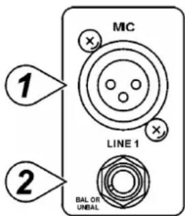
NOTE: Either the MIC or the LINE input of a given channel can be connected at one time. Never connect both simultaneously to the same channel.
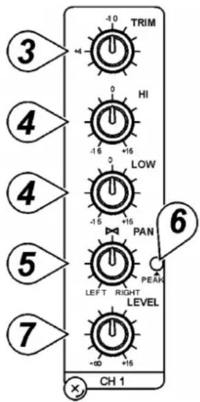
3. TRIM
The TRIM control adjusts the input sensitivity (channel gain) of the MIC and LINE inputs on the mono input channels. This control can be adjusted to accommodate input signals from a wide variety of sources, from the high outputs from keyboards or drum machines to the small signal outputs of microphones. This wide range eliminates the need for MIC / LINE switching. The best S/N balance and dynamic range will be achieved if you adjust the TRIM control on each channel separately so that the PEAK LED (6) for that channel lights occasionally.
NOTE: This control should always be turned fully anticlockwise whenever you connect or disconnect a signal source to one of the inputs.
4. EQUALIZER
All mono input channels are fitted with three-band EQ. The upper (HIGH) and lower (LOW) shelving controls have their frequencies fixed at 12kHz and 80Hz respectively. The midrange control has a peaking response, with Q fixed at 2 octaves and the frequency at 2.5kHz. All three bands have up to 15dB of cut and boost with a centre detent for "off".
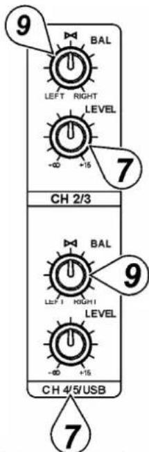
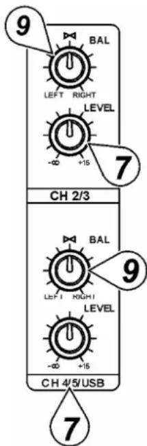
5. PAN Control
The channel PAN positions the output of the channel in the stereo field of the Master Mix. Its constant-power design ensures there are no level discrepancies whether a signal is hard-panned, centre-stage or somewhere in-between.
6. PEAK LED
The PEAK LED illuminates when a channel is going into overload. It detects the peak level after the EQ and will light at 3dB before clipping to warn that the signal is approaching overload. You do not want the PEAK LED to light except very intermittently during a take or a mix. If it does light persistently, reduce input gain with the TRIM control (3).
7. Channel LEVEL Controls
The channel LEVEL controls determine the output signal level to the MASTER MIX bus. There is no PFL function on the mixer. In order to audition any single channel for proper gain, you can turn off the gain control of all the other channels (fully anticlockwise) and set both the auditioned channel and MASTER MIX control (16) to unity gain (0dB). The LED OUTPUT meter (15) should read around 0dB.
b. Stereo Input
7. Channel LEVEL Controls
The channel LEVEL controls determine the output signal level to the MASTER MIX bus. There is no PFL function on the mixer. In order to audition any single channel for proper gain, you can turn off the gain control of all the other channels (fully anticlockwise) and set both the auditioned channel and MASTER MIX control (16) to unity gain (0dB). The LED OUTPUT meter (15) should read around 0dB.
8. LINE Input
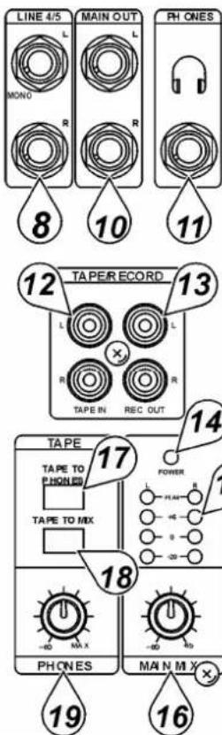
Each stereo channel has two balanced line level inputs on 14 " TRS jacks for left and right channels (tip = positive (+), ring = negative (-), sleeve = ground). If only the connector marked "L" (left) is used, the channel operates in mono. The stereo channels are designed to handle typical line level signals. The input signals to these jacks can be either balanced or unbalanced.
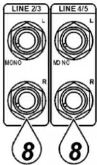
- BAL Control
For a mono input to the L (MONO) input the function of the control is the same as the PAN controls (5) of the mono channels. However, when a channel is run in stereo, this control functions as a BALANCE control, determining the relative balance of the left and right channel signals being sent to the left and right MASTER MIX buses. For example, with the BALANCE control turned fully clockwise, only the right portion of the channel's stereo signal will be routed to the MASTER MIX.
c. Master
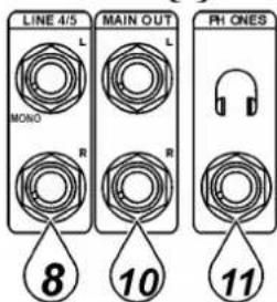
- STEREO Output
Use these jacks to connect to an external power amplifier if extra output power for a larger PA system is required. The stereo outputs are left (L) and right (R) unbalanced 14 " TRS jacks, wired as tip = positive (+), sleeve = ground.
- PHONES Output
The PHONES output will feed headphones and is a 14 " TRS jack, wired as tip = left signal, ring = right signal, sleeve = ground.
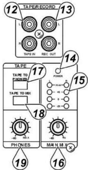
- TAPE Input
These jacks will accept the signal from an external device with a stereo output such as a cassette recorder.
- REC Output
The REC outputs also provide an output of the MASTER MIX. These outputs are RCA jacks and designed primarily for inputs to tape recorders etc.
- POWER ON LED
The red LED indicates that the console is powered on.
- VU METER
The 4-stage LED VU meter displays the MASTER MIX output level.
- MASTER MIX GAIN Control
The output level routed to the STEREO outputs and REC outputs is determined by the MASTER MIX GAIN control.
- TAPE/REC to PHONES Switch
Use the TAPE / ECHO TO PHONES switch to route signals from the TAPE input (12) to the PHONES control (19).
- TAPE/REC to MASTER Switch
Use the TAPE / ECHO TO MASTER switch to route signals from the TAPE input (12) to the MASTER MIX GAIN control (16).
- PHONES Control
The mixer allows you to monitor the MASTER MIX. The signal level is adjusted with the PHONES control and routed to the PHONES (11) output.
d. Rear Panel
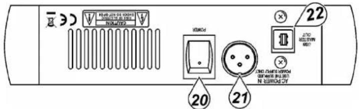
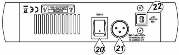
- MAIN POWER Switch
This switches the mixer ON or OFF.
NOTE: Be sure to switch on the power to your mixer before switching on the amplification system.
- AC POWER Input
Connect the enclosed power supply to the 3-pin mains connector on the rear of the console. Use the included adapter to connect the console to the mains.


e. USB
22. USB Connection
The USB connection can be used for playing MP3 or other audio files from a computer or for recording your performance to a computer. The signal is sent to channels 4/5/USB.
NOTE: Be sure to turn channels 4/5/USB all the way down before connecting/disconnecting the USB cable.
4. Connections
Unbalanced equipment may be connected to balanced inputs/outputs. Either use mono 14 " jacks or connect the ring and sleeve of TRS jacks. Never use unbalanced XLR connectors on the MIC input connectors when using a phantom power supply.
Microphone input Group & mix outputs
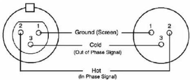
Socket
(female)
Plug
(male)
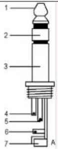 | Headphones1. Tip = left signal2. Ring = right signal3. Sleeve = ground4. Tip5. Ring6. Sleeve7. Strain relief clamp |
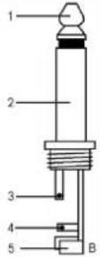 | Unbalanced use of mono 1/4" plugs1. Tip = signal2. Sleeve = ground3. Tip4. Sleeve5. Strain relief clamp |
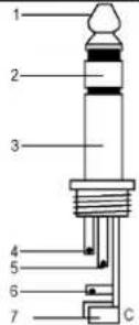 | Balanced use of stereo 1/4" plugs1. Tip = hot (+)2. Ring = cold (-)3. Sleeve = ground4. Tip5. Ring6. Sleeve7. Strain relief clamp |
5. Technical Specifications
INPUT
| Input | Connector | Input | Impedance Nominal Level Max. Level | |
| MIC MONO | XLR | >1.3k | + 2dBm | + 14dBm |
| LINE MONO | 14" TRS | >10k | + 4dBm | + 22dBm |
| LINE STEREO | 14" TRS | >10k | + 4dBm | + 22dBm |
| TAPE IN | RCA | >10k | + 2dBm | + 22dBm |
OUTPUT
| Output Connector Input Impedance | Nominal Level Max. Level | |||
| STEREO OUT L/R | 14" TRS | 120Ω | + 4~6dBm | + 22dBm |
| REC OUT | RCA | 1k Ω | + 4~6dBm | + 22dBm |
| PHONES | 14" TRS | 100Ω | - | 40mW * 2 |
FREQUENCY RESPONSE
Any Input to Any Output 20Hz\~20kHz
TOTAL HARMONIC DISTORTION
Any Input to Any Output 0.02%, 20Hz\~20kHz @ 1kHz, 0dBm
INPUT CHANNEL EQUALIZATION
High Shelving 10kHz, +/- 15dB, Q fixed at 2 oct. Low Shelving 100kHz, +/- 15dB, Q fixed at 2 oct.
GAIN CONTROL RANGE
Input Channel Trim Control stop to stop, MIC + 10dB\~+60dB, LINE +10dB\~+40dB Channel/Master Faders -∞ to +15dB
CROSSTALK @ 1kHz
Adjacent Channel Inputs -78dB\~-68dB Input to Output -78dB\~-68dB
HUM AND NOISE
20Hz\~20kHz, Rs = 150Ω, input TRIM @ 0dB, input sensitivity @ -60dB
Equivalent Input Noise -129dBm Residual Output Noise < 90dBm
USB
A/D & D/A 16-bit ΔΣ Playback Distortion < 0.05% S/N 80dB Recording Distortion < 0.1% Interface USB1.1 or USB2.0 w/ full-duplex operation (playback and recording)
VU METERS
4-segment LED x 2
POWER SUPPLY
18VAC/300mA
POWER CONSUMPTION
11W
DIMENSIONS AND WEIGHT
212 x 179 x 52mm, 1.6kg
Use this device with original accessories only. Velleman nv cannot be held responsible in the event of damage or injury resulted from (incorrect) use of this device.
For more info concerning this product, please visit our website www.hqpower.com.
The information in this manual is subject to change without prior notice.
PROMIX22U - PROFESSIONELE MENGTAFEL - 5 KANALEN - USB-IN/UIT
1. Inleiding
- TAPE/REC to MASTER Switch
d. Achterpaneel
20. VOEDINGSSCHAKELAAR
Interface USB1.1 of USB2.0 met fullduplexbediening

- Entrée TAPE
Embase
(femelle)
Fiche
(mâle)
Lecture Distorsion < 0.05%
S/B 80dB
Enregistrement Distorsion < 0.1%
b. Entrada estéreo
7. Ajuste LEVEL
Base (hembra) Conector (macho)
- BAL-Regler
- TAPE/REC to MASTER-Schalter
Buchse
Stecker

Gniazdo
Wtyk
Górne pasmo 10kHz, +/- 15dB, Q fixed at 2 oct.
Dolne pasmo 100kHz, +/- 15dB, Q fixed at 2 oct.
ZAKRES REGULACJI WZMOCNIENIA SYGNAŁU
Regulatory Trim Control stop to stop, MIC + 10dB\~+60dB, LINE +10dB\~+40dB
Residual Output Noise < 90dBm
USB
A/D & D/A 16-bit Δ Σ
Odtwarzane Znieksztalcenia < 0.05%
Dynamika S/N
Zapis Znieksztalcenia < 0.1%
WYMIARY I WAGA PRODUKTU
212 x 179 x 52mm, 1.6kg
Velleman® Service and Quality Warranty
Velleman® has over 35 years of experience in the electronics world and distributes its products in more than 85 countries.
All our products fulfil strict quality requirements and legal stipulations in the EU. In order to ensure the quality, our products regularly go through an extra quality check, both by an internal quality department and by specialized external organisations. If, all precautionary measures notwithstanding, problems should occur, please make appeal to our warranty (see guarantee conditions).
General Warranty Conditions Concerning Consumer Products (for EU):
- All consumer products are subject to a 24-month warranty on production flaws and defective material as from the original date of purchase.
- Velleman® can decide to replace an article with an equivalent article, or to refund the retail value totally or partially when the complaint is valid and a free repair or replacement of the article is impossible, or if the expenses are out of proportion.
You will be delivered a replacing article or a refund at the value of 100% of the purchase price in case of a flaw occurred in the first year after the date of purchase and delivery, or a replacing article at 50% of the purchase price or a refund at the value of 50% of the retail value in case of a flaw occurred in the second year after the date of purchase and delivery.
• Not covered by warranty:
- all direct or indirect damage caused after delivery to the article (e.g. by oxidation, shocks, falls, dust, dirt, humidity...), and by the article, as well as its contents (e.g. data loss), compensation for loss of profits;
- frequently replaced consumable goods, parts or accessories such as batteries, lamps, rubber parts, drive belts... (unlimited list);
- flaws resulting from fire, water damage, lightning, accident, natural disaster, etc. ...;
- flaws caused deliberately, negligently or resulting from improper handling, negligent maintenance, abusive use or use contrary to the manufacturer's instructions; - damage caused by a commercial, professional or collective use of the article (the warranty validity will be reduced to six (6) months when the article is used professionally);
- damage resulting from an inappropriate packing and shipping of the article;
- all damage caused by modification, repair or alteration performed by a third party without written permission by Velleman®.
- Articles to be repaired must be delivered to your Velleman® dealer, solidly packed (preferably in the original packaging), and be completed with the original receipt of purchase and a clear flaw description.
- Hint: In order to save on cost and time, please reread the manual and check if the flaw is caused by obvious causes prior to presenting the article for repair. Note that returning a non-defective article can also involve handling costs.
• Repairs occurring after warranty expiration are subject to shipping costs.
- The above conditions are without prejudice to all commercial warranties.
The above enumeration is subject to modification according to the article (see article's manual).

- To all residents of the European Union
- Important environmental information about this product
- Safety Instructions
- Description
- a. Mono Input
- MIC Input
- LINE Input
- TRIM
- EQUALIZER
- PAN Control
- PEAK LED
- Channel LEVEL Controls
- b. Stereo Input
- LINE Input
- c. Master
- d. Rear Panel
- e. USB
- USB Connection
- Connections
- Technical Specifications
- FREQUENCY RESPONSE
- TOTAL HARMONIC DISTORTION
- INPUT CHANNEL EQUALIZATION
- GAIN CONTROL RANGE
- CROSSTALK @ 1kHz
- HUM AND NOISE
- USB
- VU METERS
- POWER SUPPLY
- POWER CONSUMPTION
- DIMENSIONS AND WEIGHT
- PROMIX22U - PROFESSIONELE MENGTAFEL - 5 KANALEN - USB-IN/UIT
- Inleiding
- d. Achterpaneel
- VOEDINGSSCHAKELAAR
- b. Entrada estéreo
- Ajuste LEVEL
- ZAKRES REGULACJI WZMOCNIENIA SYGNAŁU
- WYMIARY I WAGA PRODUKTU
- Velleman® Service and Quality Warranty
- General Warranty Conditions Concerning Consumer Products (for EU):
- • Not covered by warranty:
- The above enumeration is subject to modification according to the article (see article's manual).
Brand : VELLEMAN
Model : PROMIX22U
Category : Mixer