
BP 5 - Water pump Kärcher - Free user manual and instructions
Find the device manual for free BP 5 Kärcher in PDF.
User questions about BP 5 Kärcher
0 question about this device. Answer the ones you know or ask your own.
Ask a new question about this device
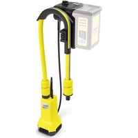
Download the instructions for your Water pump in PDF format for free! Find your manual BP 5 - Kärcher and take your electronic device back in hand. On this page are published all the documents necessary for the use of your device. BP 5 by Kärcher.
USER MANUAL BP 5 Kärcher
natural_image
Two yellow portable water purifiers with black and white designs, one with a coiled cable (no visible text or symbols)A
natural_image
Close-up of a yellow car hood with black plastic wrap and a numbered label (15) pointing to the handle area.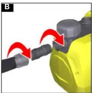
natural_image
Close-up of a yellow industrial component with red arrows indicating motion or assembly (no text or symbols)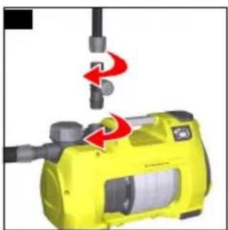
natural_image
Yellow industrial machine with red arrows indicating motion or change, no visible text or symbols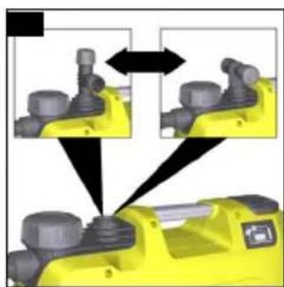
natural_image
Diagram showing mechanical assembly with yellow components and black arrows indicating direction (no text or symbols)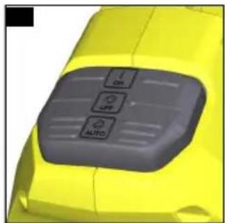
natural_image
Close-up of a yellow car's front panel with gray buttons and 'AUTO' label (no readable text or symbols beyond basic icons)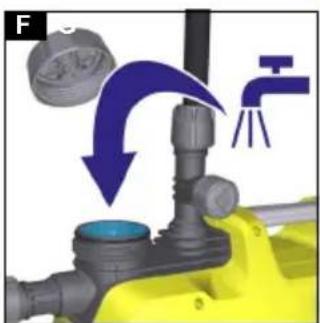
natural_image
Mechanical assembly diagram showing a valve mechanism with red arrows indicating motion direction (no text or symbols)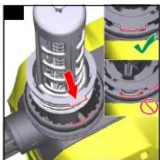
natural_image
Close-up of a mechanical component with highlighted parts and a red arrow indicating a specific section (no text or symbols present)Inhalt
Chairman of the Board of Management
S. Reiser
Director Regulatory Affairs & Certification
71364 Winnenden (Germany)
Tel.: +49 7195 14-0
Fax: +49 7195 14-2212
Winnenden, 2018/07/01
Contents
General notes....8
Intended use....8
Environmental protection 8
Accessories and spare parts 8
Scope of delivery 9
Warranty....9
Safety devices 9
Description of the unit. 9
Startup 9
Operation 10
Transport 10
Storage....11
Care and service 11
Troubleshooting guide .... 11
Technical data 12
EU Declaration of Conformity....13
General notes


Read these original operating instructions and the enclosed safety instructions before using the device for the first
time. Act in accordance with them.
Keep both books for future reference or for future owners.
Intended use
The requirements of EN 1717 must be observed when connecting this product to the drinking water network.
Ask your sanitation specialist or a qualified specialist if necessary.
Use the device only in private households.
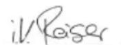
The constant operating pressure makes this device suitable for use in the house and garden:
● Supplying washing machines or toilets in a house, e.g. in conjunction with a water tank
- Garden watering
For notes on functionality, see chapter Functional principle of the pump in Automatic mode.
Permissible feed fluids
Permissible feed fluids:
- Processed water
- Well water
- Spring water
- Rain water
- Swimming pool water with intended dosage of additives
The temperature of the delivered liquid must not exceed 35^ C.
Improper use
Note
The manufacturer accepts no liability for possible damage caused by improper use or incorrect operation.
ATTENTION
Using the pump for increasing the existing water pipe pressure
Damage to the pump through incorrect use
Observe the technical data.
The device is not suitable for continuous pump operation (e.g. lifting system, fountain pump). The device is protected by a dry run fuse (see also chapter Dry run fuse).
Environmental protection

The packing materials can be recycled. Please dispose of packaging in accordance with the environmental regulations.

Electrical and electronic appliances contain valuable, recyclable materials and often components such as batteries, rechargeable batteries or oil, which - if handled or disposed of incorrectly - can
pose a potential threat to human health and the environment. However, these components are required for the correct operation of the appliance. Appliances marked by this symbol are not allowed to be disposed of together with the household rubbish.
Notes on the content materials (REACH)
Current information on content materials can be found at: www.kaercher.com/REACH
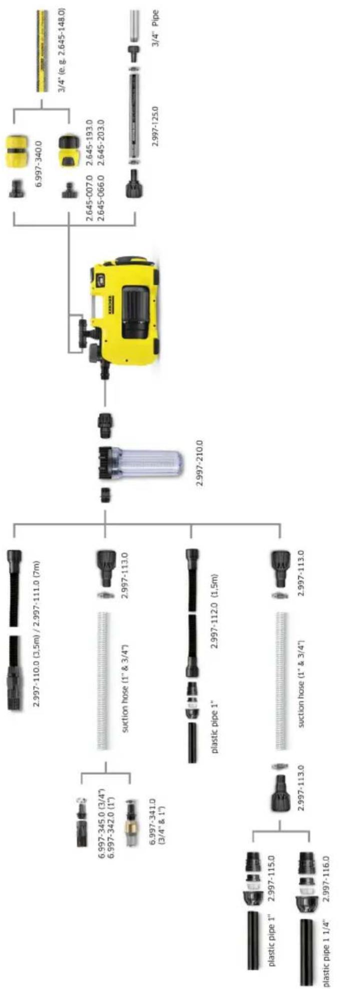
Accessories and spare parts
Only use original accessories and original spare parts. They ensure that the appliance will run fault-free and safely.
Information on accessories and spare parts can be found at www.kaercher.com and at the end of this manual.
Scope of delivery
The scope of delivery for the appliance is shown on the packaging. Check the contents for completeness when unpacking. If any accessories are missing or in the event of any shipping damage, please notify your dealer.
Warranty
The warranty conditions issued by our relevant sales company apply in all countries. We shall remedy possible malfunctions on your appliance within the warranty period free of cost, provided that a material or manufacturing defect is the cause. In a warranty case, please contact your dealer (with the purchase receipt) or the next authorised customer service site. (See overleaf for the address)
Safety devices
△CAUTION
Missing or modified safety devices
Safety devices are provided for your own protection. Never modify or bypass safety devices.
Dry run fuse
The device detects an absent or inadequate water supply. The pump switches off if water is not sucked and delivered within a certain time after switching on. This occurs after 4 minutes in Manual mode and after 3 minutes in Automatic mode. The "Suction side error" LED on the display lights up.
Description of the unit
The maximum amount of equipment is described in these operating instructions. Depending on the model used, there are differences in the scope of delivery (see packaging).
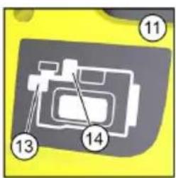
For the illustrations, refer to the graphics page Illustration A
① Connection adapter for pumps G1
② Connection G1 (33.3 mm) suction line (inlet)
③ Filling nozzle
④ Pre-filter and integrated check valve
⑤ Cover
⑥ Cap, 2-way connection adapter
⑦2-way connection adapter for pumps G1
⑧ Connection G1 (33.3 mm) pressure line (outlet)
⑨ ON/OFF switch
⑩ Cable storage and power supply cable with plug
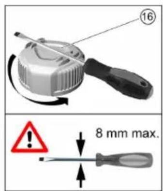
⑪ Fault display
⑫ Rubber feet
⑬ LED "Error on suction side"
⑭ LED "Error on pressure side"
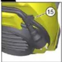
⑮ Cable clip
⑯ Opening assistance
Startup
We recommend using only original Kärcher suction hoses, filter components and hose connections. Using components from other manufacturers can lead to malfunctions when sucking the feed fluid, especially when using bayonet connection systems.
Mobile use
Note
Even minor leaks lead to malfunctions.
Connect the suction hose
Note
We recommend using a suction hose with a backflow stop. The backflow stop reduces the re-sucking time because it prevents the suction hose from draining after water is dispensed. Do not install the backflow stop directly at the pump.
Note
We recommend using an additional pre-filter if sandy water is to be delivered. Install the pre-filter between the suction hose and pump.
For information on the backflow stop and pre-filter, see chapter Accessories and spare parts.
-
Screw the connection adapter into the suction connection of the pump (inlet) and tighten hand-tight. Illustration B
-
Connect a vacuum-tight suction hose.
Connecting the pressure line
- Screw the 2-way connection adapter into the pressure connection of the pump (outlet) and tighten hand-tight.
The 2-way connection adapter allows simultaneous operation of 2 devices (e.g. washing machine and sprinkler). It can be installed with both outlets at the side or one outlet at the side and one outlet above.
Illustration C
Illustration D
-
Connect the pressure line.
-
Close the unused outlet with the cap supplied if only one outlet is used.
Filling the pump
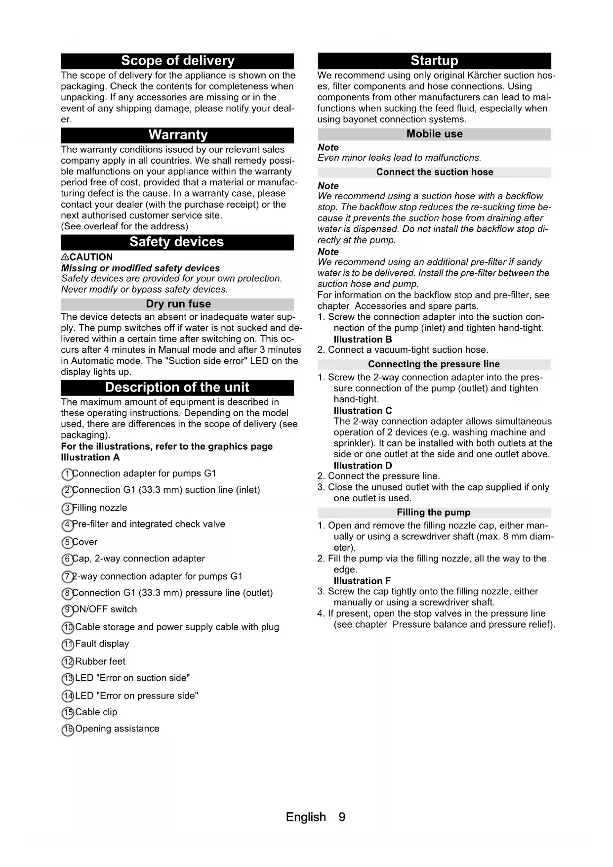
-
Open and remove the filling nozzle cap, either manually or using a screwdriver shaft (max. 8 mm diameter).
-
Fill the pump via the filling nozzle, all the way to the edge.
Illustration F
-
Screw the cap tightly onto the filling nozzle, either manually or using a screwdriver shaft.
-
If present, open the stop valves in the pressure line (see chapter Pressure balance and pressure relief).
Permanent installation
-
Connect the suction hose and pressure line (see chapter Mobile use). Use screw connections and not quick couplings in a permanent installation.
-
Fill the pump (see chapter Filling the pump).
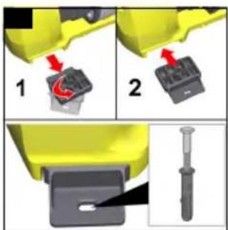
Fastening the pump
In a permanent installation, the pump can be screwed to a suitable surface.
- Pull out and rotate the rubber feet on both sides of the casing.
Illustration G
-
Insert the rubber feet into the casing.
-
Screw the pump tightly to a level surface using suitable screws.
Pressure balance and pressure relief
For a permanent installation we recommend installing flexible components, such as e.g. a flexible pressure equalization hose, on the pressure side (see chapter Accessories and spare parts). This has the following advantages:
● Greater flexibility in erection and commissioning
● Sound reduction since no vibration is transmitted in to the pipes of the house water system
● The pump switches less often in the case of minor leaks
We recommend installing a stop valve (not included in the scope of delivery) between the pump and pressure line to simplify draining and pressure relief in the system. Closing the stop cock prevents water from flowing out of the pressure line when the pump is drained.
If there are increased drops in pressure due to leaks in the house system the pump regularly switches on without dispensing water. In this case we recommend installing a pressure equalization container (see chapter Accessories and spare parts).
Operation
Starting operation
- Plug the mains plug into the socket.
- Switch the device on with the ON/OFF switch.
Illustration E
- Use the "I/On" switch setting for Manual operation.
- Use the "Auto" switch setting for Automatic mode (see also chapter Functional principle of the pump in Automatic mode).
Note
The ON/OFF switch can be conveniently operated by foot.
- Lift the pressure hose approx. 1 m to reduce the suction time.
- Wait until the pump simultaneously sucks and delivers.
If the water supply is too low the dry run fuse switches the device off (see chapter Dry run fuse).
Functional principle of the pump in Automatic mode
In Automatic mode, the house and garden pumps automatically maintain the pressure:
● The pump starts when water is dispensed and the pressure falls below approx. 0.13 MPa (1.3 bar).
- The pump continues running when the flow rate is greater than approx. 60 l/h.
- Pressure builds up in the system again when water dispensing stops. The pump continues running for a short after-running time and then enters standby mode.
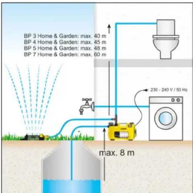
Optimising the flow rate
The flow rate is further increased:
● The lower the delivery height is
● The greater the diameter of the hose used is
● The shorter the hose used is
● The smaller the pressure loss caused by the connected up accessories
line
| l/h | BP 7 Hm e & Garden | BP 5 Hm e & Garden | BP 4 Home & Garden | BP 3 Home & Garden | | ------ | ------------------ | ------------------ | ------------------ | ------------------ | | 0 | 60 | 50 | 40 | 40 | | 2000 | 55 | 45 | 35 | 35 | | 4000 | 45 | 35 | 25 | 25 | | 6000 | 0 | 0 | 0 | 0 |Ending operation
- Switch off the device at the ON/OFF switch.
- Pull the mains plug out of the socket.
Observe the additional notes if the device is to be switched on after a longer standstill period (see chapter Care and service).
Transport
- Carry the device.
△CAUTION
Loose cable and hoses lying on the ground Danger of tripping
Watch out the cables and hoses when relocating the device in mobile operation.
Roll the cable onto the cable holder and secure with the cable clip.
a Lift up the device by the carrying handle, and carry it.
● Transport the device in a vehicle.
a Secure the device against slipping and tipping over.
Storage
ATTENTION
Danger of frost
Incompletely emptied devices can be destroyed by frost.
Completely empty the device and accessories.
Protect the device from frost.
-
Open the pressure side water dispenser (e.g. water tap).
The device is depressurised. -
Drain the hoses.
- Remove the suction line and pressure line.
- Open and remove the filling nozzle cap, either manually or using a screwdriver shaft.
- Clean the pre-filter (see chapter Cleaning the prefilter).
- Turn the pump over and completely empty via the filling nozzle.
- Install the pre-filter.
- Install the cover.
- Store the pump in a frost-protected place.
Care and service
The device is maintenance-free, i.e. you do not need to perform periodic maintenance work.
Pressure relief
- Open and close the pressure valves attached for pressure relief.
The system is depressurised.
Flushing the pump
- Flush the pump with clear water if water with additives has been delivered.
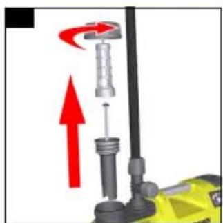
Cleaning the pre-filter
Check the pre-filter for contamination and clean if necessary.
- Open and remove the filling nozzle cap, either manually or using a screwdriver shaft.
- Remove the pre-filter with integrated check valve. Illustration H
- Disconnect the check valve from the pre-filter.
- Clean the pre-filter and check valve thoroughly under running water.
- If necessary, flush any dirt residues out of the pump.
- Check the freedom of movement of the check valve.
ATTENTION
Use of unsuitable lubricant
Damage to the seals
Use the grease (6.288-143.0) available from Kärcher Service.
Use only grease free of mineral oil for the seals.
- Lubricate the seals if the connections do not move freely.
- Connect the pre-filter to the check valve.
- Fit the pre-filter into the filling nozzle without using unnecessary force. Ensure the correct installation position (cutouts).
Illustration I
Troubleshooting guide
Malfunctions often have simple causes that you can remedy yourself using the following overview. When in doubt, or in the case of malfunctions not mentioned here, please contact your authorised Customer Service.
Pump is running, but not delivering
Air is in the pump.
- Check for correct startup (see chapter Startup and Starting operation).
Dirt particles block the suction area. - Pull the mains plug out of the socket.
- Clean the suction area.
The pre-filter is soiled.
- Pull the mains plug out of the socket.
- Allow the pump to cool down.
- Clean the suction area.
- Clean the pre-filter (see chapter Cleaning the prefilter).
- Flush dirt residues at the base of the filling nozzle out through the filling hole.
- Switch on the pump.
The suction hose or the connection adapter is not correctly screwed in.
- Check that the seals are fitted correctly.
- Manually tighten the suction hose and connection adapter.
The pump does not start up, or stops suddenly during operation
The power supply is disconnected.
-
Check the fuses and the electrical connections.
The pre-filter is soiled. -
Clean the pre-filter (see chapter Cleaning the prefilter).
- Flush dirt residues at the base of the filling nozzle out through the filling hole.
The pump is in Automatic mode and the pressure in the system is greater than 1.3 bar.
In Automatic mode, the device does not run when an internal pressure greater than 1.3 bar is present, i.e. a water column greater than 13 m works against the pump.
- Reduce the pressure in the system.
The pump switches on automatically when the pressure in the system drops below 1.3 bar.
The pump stops, the "Suction side error" LED lights up
The flow is interrupted, pressure is not built up.
- Pull the mains plug out of the socket.
- Check that sufficient water is present in the suction container (e.g. water tank).
- Check the suction side connections for leaks.
- Clean the pre-filter (see chapter Cleaning the prefilter).
-
Flush dirt residues at the base of the filling nozzle out through the filling hole.
-
Switch on the pump.
The flow is too small, the dry run fuse has switched off the pump.
-
Check that sufficient water is present in the suction container (e.g. water tank).
-
Open the water tap further.
The flow rate increases.
Suction problem due to a leak or a connected water tap. The pump does not end the suction mode.
- Open the water tap.
- Check the system for leaks.
Install a pressure equalization container if the leaks cannot be eliminated (see chapter Accessories and spare parts).
The pump stops in Automatic mode, the "Pressure side error" LED lights up
The pump switches frequently on and off due to leaks.
- Check the pressure side for leaks (e.g. dripping water tap).
Install a pressure equalization container if the leaks cannot be eliminated (see chapter Accessories and spare parts).
- Switch on the pump.
The pressure is too low after switching off the pump.
The device starts again immediately and switches frequently on and off.
- Increase the pressure at the pressure side.
- For garden applications, use a garden hose with minimum length of 5 m when the diameter is 34" or 15 m when the diameter is 12" .
- With a permanent installation, install a pressure equalization hose or pressure equalization container (see chapter Accessories and spare parts).
- Switch on the pump.
The pump stops in Manual mode, the "Pressure side error" LED lights up
The pump runs for at least 4 minutes, although the pressure side outlet (e.g. water tap) is closed. The overheat protection switches off the device.
-
Pull the mains plug out of the socket.
-
Open the water dispenser connected to the pressure side.
The device is depressurised.
- Switch on the pump.
The pump capacity drops or is too low.
Dirt particles block the suction area.
-
Pull the mains plug out of the socket.
-
Clean the suction area.
The pre-filter is soiled.
-
Pull the mains plug out of the socket.
-
Allow the pump to cool down.
-
Clean the suction area.
-
Clean the pre-filter (see chapter Cleaning the prefilter).
-
Flush dirt residues at the base of the filling nozzle out through the filling hole.
-
Switch on the pump.
The suction side is leaking.
- Check the suction side for leaks.
The maximum lifting height is exceeded or the flow rate is not optimised.
-
Observe the maximum lifting height (see chapter Technical data).
-
If necessary, select a different hose diameter or a different hose length (see chapter Optimising the flow rate).
The pressure side outlet is restricted.
- Fully open the valve or ball tap.
The pressure side hose is kinked.
- Eliminate the kink points in the hose.
Technical data
| B & Garden | BP 4 Home & Garden | BP 5 Home & Garden | BP 7 Home & Garden | ||
| Electrical connection | |||||
| Mains voltage V 230-240 230-240 230-240 230-240 | |||||
| Power frequency Hz 50 50 50 50 | |||||
| Nominal power | W | 800 | 950 | 1000 | 1200 |
| Device performance data | |||||
| Maximum flow rate | l/h | 3300 | 3800 | 6000 | 6000 |
| Suction height (max.) | m | 8 | 8 | 8 | 8 |
| Pressure (max.) | MPa (bar) | 0,40 (4,0) | 0,45 (4,5) | 0,48 (4,8) | 0,60 (6,0) |
| Delivery height (max.) | m | 40 45 48 60 | |||
| Switch-on pressure in automatic mode (max.) | MPa (bar) | 0,13 (1,3) | 0,13 (1,3) | 0,13 (1,3) | 0,13 (1,3) |
| Particle size (max.) of permissible feed fluids | mm | 1 | 1 | 1 | 1 |
| Pump type | Jet | Jet | Multistage 4-stage | Multistage 5-stage | |
| LED type to EN 60825-1 | Class 1 | Class 1 | Class 1 | Class 1 | |
| Application instructions | |||||
| Watering (max.) | m^2 | 500 | 800 | 1000 | 1200 |
| House supply (max.) | Persons | 8 | 10 12 12 | ||
| Watering + house supply with 4 persons (max.) | m^2 | 300 | 600 | 800 | 900 |
| Dimensions and weights | |||||
| Weight (without accessories) | kg | 10,3 | 10,6 | 12,5 | 13,0 |
| Determined values to EN ISO 20361 | |||||
| Sound level L_pA | dB(A) | 61 | 63 | 61 | 61 |
| dB(A) | 76 | 78 | 77 | 76 | |
Subject to technical modifications.
EU Declaration of Conformity
We hereby declare that the machine described below complies with the relevant basic safety and health requirements in the EU Directives, both in its basic design and construction as well as in the version placed in circulation by us. This declaration is invalidated by any changes made to the machine that are not approved by us.
Product: Pump
Type: 1.645-xxx
Currently applicable EU Directives
2014/35/E
2014/30/EU
2000/14/EC
2011/65/EU
Harmonised standards used
EN 60335-1
EN 60335-2-41
EN 62233: 2008
EN 55014-1: 2006+A1: 2009+A2: 2011
EN 55014-2: 1977+A1: 2001+A2: 2008
EN 61000-3-2: 2014
EN 61000-3-3: 2013
EN 50581
Applied conformity evaluation method
2000/14/EG: Appendix V
Sound power level dB(A)
BP2 G
Measured: 69
Guaranteed: 72
BP3 G, BP3 G Set +, BP3 H&G
Measured: 73
Guaranteed: 76
BP4 G
Measured: 72
Guaranteed: 75
BP4 H&G eco
Measured: 75
Guaranteed: 78
BP5 H&G
Measured: 74
Guaranteed: 77
BP7 H&G eco
Measured: 73
Guaranteed: 76
The signatories act on behalf of and with the authority of the company management.
H. Jenner
Chairman of the Board of Management
S. Reiser
Director Regulatory Affairs & Certification
Documentation supervisor: S. Reiser
Alfred Kärcher SE & Co. KG
Alfred-Kärcher-Str. 28 - 40
71364 Winnenden (Germany)
Ph.: +49 7195 14-0
Fax: +49 7195 14-2212
Responsable de la documentation : S. Reiser
Alfred Kärcher SE & Co. KG
Alfred-Kärcher-Str. 28 - 40
71364 Winnenden (Germany)
71364 Winnenden (Germany)
Tel.: +49 7195 14-0
Fax: +49 7195 14-2212
Winnenden, 01/07/2018
Inhoud
71364 Winnenden (Germany)
Tel.: +49 7195 14-0
Fax: +49 7195 14-2212
Winnenden, 2018/07/01
71364 Winnenden (Germany)
Tel.: +49 7195 14-0
Fax: +49 7195 14-2212
Winnenden, 2018/07/01
Índice
Chairman of the Board of Management

S. Reiser
Director Regulatory Affairs & Certification
71364 Winnenden (Germany)
Tηλ.: +49 7195 14-0
Φαξ: +49 7195 14-2212
Winnenden, 2018/07/01
İçindekiler
Winnenden, 2018/07/01
flowchart
graph TD
    A["Device"] --> B["Component 1"]
    A --> C["Component 2"]
    A --> D["Component 3"]
    A --> E["Component 4"]
    A --> F["Component 5"]
    A --> G["Component 6"]
    A --> H["Component 7"]
    A --> I["Component 8"]
    A --> J["Component 9"]
    A --> K["Component 10"]
    A --> L["Component 11"]
    A --> M["Component 12"]
    A --> N["Component 13"]
    A --> O["Component 14"]
    A --> P["Component 15"]
    A --> Q["Component 16"]
    A --> R["Component 17"]
    A --> S["Component 18"]
    A --> T["Component 19"]
    A --> U["Component 20"]
    A --> V["Component 21"]
    A --> W["Component 22"]
    A --> X["Component 23"]
    A --> Y["Component 24"]
    A --> Z["Component 25"]
    A --> AA["Component 26"]
    A --> AB["Component 27"]
    A --> AC["Component 28"]
    A --> AD["Component 29"]
    A --> AE["Component 30"]
    A --> AF["Component 31"]
    A --> AG["Component 32"]
    A --> AH["Component 33"]
    A --> AI["Component 34"]
    A --> AJ["Component 35"]
    A --> AK["Component 36"]
    A --> AL["Component 37"]
    A --> AM["Component 38"]
    A --> AN["Component 39"]
    A --> AO["Component 40"]
    A --> AP["Component 41"]
    A --> AQ["Component 42"]
    A --> AR["Component 43"]
    A --> AS["Component 44"]
    A --> AT["Component 45"]
    A --> AU["Component 46"]
    A --> AV["Component 47"]
    A --> AW["Component 48"]
    A --> AX["Component 49"]
    A --> AY["Component 50"]
    A --> AZ["Component 51"]
    A --> BA["Component 52"]
    A --> BB["Component 53"]
    A --> BC["Component 54"]
    A --> BD["Component 55"]
    A --> BE["Component 56"]
    A --> BF["Component 57"]
    A --> BG["Component 58"]
    A --> BH["Component 59"]
    A --> BI["Component 60"]
    A --> BJ["Component 61"]
    A --> BK["Component 62"]
    A --> BL["Component 63"]
    A --> BM["Component 64"]
    A --> BN["Component 65"]
    A --> BO["Component 66"]
    A --> BP["Component 67"]
    A --> BQ["Component 68"]
    A --> BR["Component 69"]

natural_image
Black and white icon of a hand giving a thumbs-up gesture (no text or symbols)THANK YOU!
MERCI! DANKE! iGRACIAS!

Register your product and benefit from many advantages.
www.kaercher.com/welcome


Rate your product and tell us your opinion.
natural_image
Icon showing a gear and wrench inside a square frame (no text or symbols)www.kaercher.com/dealersearch
Alfred Kärcher SE & Co. KG
Alfred-Kärcher-Str. 28-40
71364 Winnenden (Germany)
Tel.: +49 7195 14-0
Fax: +49 7195 14-2212

- Inhalt
- Contents
- General notes
- Intended use
- Permissible feed fluids
- Improper use
- Note
- ATTENTION
- Using the pump for increasing the existing water pipe pressure
- Environmental protection
- Notes on the content materials (REACH)
- Accessories and spare parts
- Scope of delivery
- Warranty
- Safety devices
- △CAUTION
- Missing or modified safety devices
- Dry run fuse
- Description of the unit
- For the illustrations, refer to the graphics page Illustration A
- Startup
- Mobile use
- Connect the suction hose
- Connecting the pressure line
- Illustration C
- Illustration D
- Filling the pump
- Illustration F
- Permanent installation
- Fastening the pump
- Illustration G
- Pressure balance and pressure relief
- Operation
- Starting operation
- Illustration E
- Functional principle of the pump in Automatic mode
- Optimising the flow rate
- Ending operation
- Transport
- Storage
- Danger of frost
- Care and service
- Pressure relief
- Flushing the pump
- Cleaning the pre-filter
- Use of unsuitable lubricant
- Illustration I
- Troubleshooting guide
- Pump is running, but not delivering
- The pump stops, the "Suction side error" LED lights up
- The pump stops in Automatic mode, the "Pressure side error" LED lights up
- The pump stops in Manual mode, the "Pressure side error" LED lights up
- The pump capacity drops or is too low.
- EU Declaration of Conformity
- Currently applicable EU Directives
- Harmonised standards used
- Applied conformity evaluation method
- Sound power level dB(A)
- BP2 G
- BP3 G, BP3 G Set +, BP3 H&G
- BP4 G
- BP4 H&G eco
- BP5 H&G
- BP7 H&G eco
- Inhoud
- Índice
- İçindekiler
- THANK YOU!
- MERCI! DANKE! iGRACIAS!
Brand : Kärcher
Model : BP 5
Category : Water pump