
BHR202RFX - Drill MAKITA - Free user manual and instructions
Find the device manual for free BHR202RFX MAKITA in PDF.
| Product type | Cordless hammer drill |
| Model | BHR202RFX |
| Brand | Makita |
| Overall length | 316 mm |
| Net weight | 4 kg |
| Power source | 24 V DC battery (NiMH) |
| Drilling capacity (concrete) | 20 mm |
| Drilling capacity (steel) | 27 mm |
| Drilling capacity (wood) | 13 mm |
| No load speed | 0-1100 min⁻¹ |
| Impact rate | 0-4700 blows/min |
| Operating modes | Rotation with hammer, rotation only, hammer only |
| Side handle | Yes, adjustable (left/right) |
| Depth rod | Yes, adjustable |
| Dust collector | Yes, for overhead drilling |
| Torque limiter | Yes |
| Chuck type | SDS-plus |
| Maintenance | Regular cleaning, carbon brush replacement |
| Sound pressure level | 89 dB(A) |
| Sound power level | 102 dB(A) |
| Charging temperature | 10 °C to 40 °C |
| Included accessories | Charger, battery, side handle, depth rod, blow bulb, dust collector, foot |
Frequently Asked Questions - BHR202RFX MAKITA
User questions about BHR202RFX MAKITA
0 question about this device. Answer the ones you know or ask your own.
Ask a new question about this device
Download the instructions for your Drill in PDF format for free! Find your manual BHR202RFX - MAKITA and take your electronic device back in hand. On this page are published all the documents necessary for the use of your device. BHR202RFX by MAKITA.
USER MANUAL BHR202RFX MAKITA
GB Cordless Rotary Hammer Instruction Manual
natural_image
Line drawing of a Makita electric drill press tool (no text or symbols on the device itself)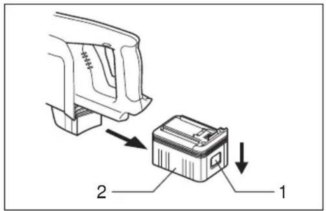
1
2
3
4
5
6
7
8
9
10
natural_image
Line drawing of hands using a twist drill to adjust a mechanical component (no text or symbols)11 12
13 14
15 16
natural_image
Line drawing of a hand using a drill bit into a cylindrical tool, no text or symbols present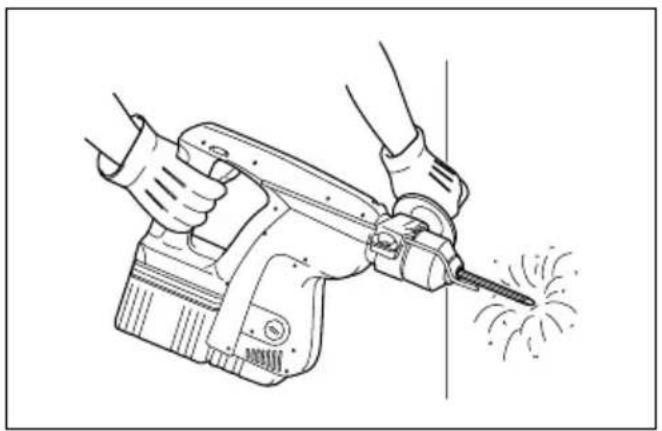
natural_image
Line drawing of a hand using a power tool to cut sparks, no text or symbols present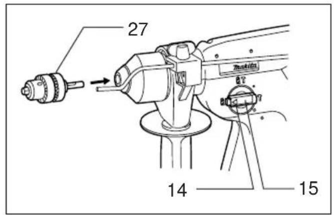
17 18
natural_image
Line drawing of a hand holding a tool with arrows indicating motion or force (no text or symbols)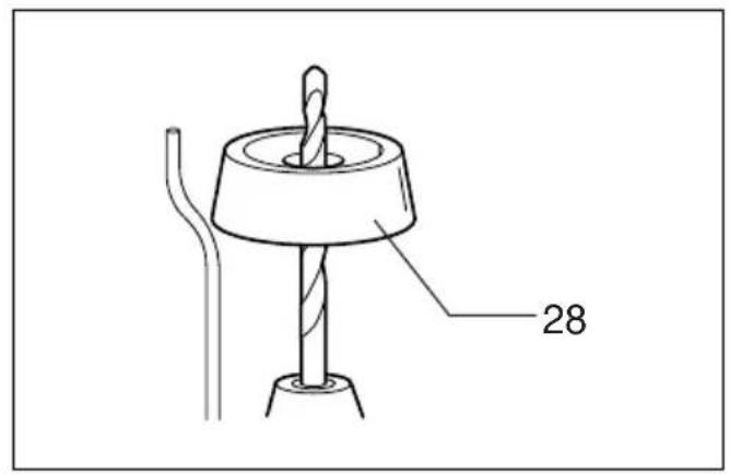
19 20
21 22
23 24
ENGLISH
| Explanation of general view | ||
| 1 Button | 13 Lock button | 25 Loosen |
| 2 Battery cartridge | 14 Pointer | 26 Side grip |
| 3 Terminal cover | 15 Change lever | 27 Drill chuck |
| 4 Battery charger | 16 Rotation only | 28 Dust cup |
| 5 Charging lights | 17 Hammering only | 29 Foot |
| 6 Switch trigger | 18 Bit shank | 30 Battery cartridge |
| 7 Reversing switch lever | 19 Bit grease | 31 Screw |
| 8 A side | 20 Bit | 32 Battery cartridge |
| 9 B side | 21 Chuck cover | 33 Limit mark |
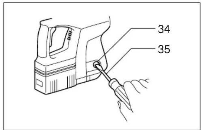
| 10 Clockwise | 22 Depth gauge | 34 Brush holder cap |
| 11 Counterclockwise | 23 Clamp screw | 35 Screwdriver |
| 12 Rotation with hammering | 24 Tighten | |
SPECIFICATIONS
Model BHR200
Capacities
Concrete 20mm
Wood 27 mm
Steel 13 mm
No load speed (min ^-1 ) 0 - 1,100
Overall length 316 mm
Net weight 4 kg
Rated voltage D.C.24V
- Due to our continuing program of research and development, the specifications herein are subject to change without notice.
- Note: Specifications may differ from country to country.
Safety hints
For your own safety, please refer to the enclosed safety instructions.
IMPORTANT SAFETY INSTRUCTIONS FOR CHARGER & BATTERY CARTRIDGE
ENC002-2
- SAVE THESE INSTRUCTIONS — This manual contains important safety and operating instructions for battery charger.
- Before using battery charger, read all instructions and cautionary markings on (1) battery charger, (2) battery, and (3) product using battery.
- CAUTION — To reduce risk of injury, charge only MAKITA type rechargeable batteries. Other types of batteries may burst causing personal injury and damage.
- Do not expose charger to rain or snow.
- Use of an attachment not recommended or sold by the battery charger manufacturer may result in a risk of fire, electric shock, or injury to persons.
- To reduce risk of damage to electric plug and cord, pull by plug rather than cord when disconnecting charger.
- Make sure cord is located so that it will not be stepped on, tripped over, or otherwise subjected to damage or stress.
-
Do not operate charger with damaged cord or plug — replace them immediately.
-
Do not operate charger if it has received a sharp blow, been dropped, or otherwise damaged in any way; take it to a qualified serviceman.
- Do not disassemble charger or battery cartridge; take it to a qualified serviceman when service or repair is required. Incorrect reassembly may result in a risk of electric shock or fire.
- To reduce risk of electric shock, unplug charger from outlet before attempting any maintenance or cleaning. Turning off controls will not reduce this risk.
- The battery charger is not intended for use by young children or infirm persons without supervision.
- Young children should be supervised to ensure that they do not play with the battery charger.
ADDITIONAL SAFETY RULES FOR CHARGER & BATTERY CARTRIDGE
- Do not charge battery cartridge when temperature is BELOW 10^ C ( 50^ F) or ABOVE 40^ C ( 104^ F).
- Do not attempt to use a step-up transformer, an engine generator or DC power receptacle.
-
Do not allow anything to cover or clog the charger vents.
-
Do not short the battery cartridge:
(1) Do not touch the terminals with any conductive material.
(2) Avoid storing battery cartridge in a container with other metal objects such as nails, coins, etc.
(3) Do not expose battery cartridge to water or rain.
A battery short can cause a large current flow, overheating, possible burns and even a breakdown.
-
Do not store the tool and battery cartridge in locations where the temperature may reach or exceed 50^ C ( 122^ F).
-
Do not incinerate the battery cartridge even if it is severely damaged or is completely worn out. The battery cartridge can explode in a fire.
-
Be careful not to drop, shake or strike battery.
-
Do not charge inside a box or container of any kind. The battery must be placed in a well ventilated area during charging.
ADDITIONAL SAFETY RULES FOR TOOL
ENB028-1
- Be aware that this tool is always in an operating condition, because it does not have to be plugged into an electrical outlet.
- Hold tool by insulated gripping surfaces when performing an operation where the cutting tool may contact hidden wiring. Contact with a "live" wire will make exposed metal parts of the tool "live" and shock the operator.
- Wear ear protectors when using the tool for extended periods. Prolonged exposure to high intensity noise can cause hearing loss.
- Wear a hard hat (safety helmet), safety glasses and/or face shield. It is also highly recommended that you wear a dust mask and thickly padded gloves.
- Be sure the bit is secured in place before operation.
- Under normal operation, the tool is designed to produce vibration. The screws can come loose easily, causing a breakdown or accident. Check tightness of screws carefully before operation.
- In cold weather or when the tool has not been used for a long time, let the tool warm up for several minutes by operating it under no load. This will loosen up the lubrication. Without proper warm-up, hammering operation is difficult.
- Always be sure you have a firm footing.
-
Be sure no one is below when using the tool in high locations.
-
Hold the tool firmly with both hands.
- Keep hands away from moving parts.
- Do not leave the tool running. Operate the tool only when hand-held.
- Do not point the tool at any one in the area when operating. The bit could fly out and injure someone seriously.
- Do not touch the bit or parts close to the bit immediately after operation; they may be extremely hot and could burn your skin.
SAVE THESE INSTRUCTIONS.
OPERATING INSTRUCTIONS
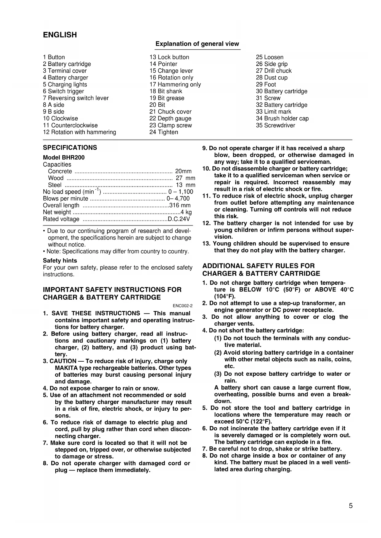
Installing or removing battery cartridge (Fig. 1)
- Always switch off the tool before insertion or removal of the battery cartridge.
- To remove the battery cartridge, withdraw it from the tool while sliding the button on the cartridge.
- To insert the battery cartridge, align the tongue on the battery cartridge with the groove in the housing and slip it into place. Always insert it all the way until it locks in place with a little click. If you can see the red part on the upper side of the button, it is not locked completely. Insert it fully until the red part cannot be seen. If not, it may accidentally fall out of the tool, causing injury to you or someone around you.
- Do not use force when inserting the battery cartridge. If the cartridge does not slide in easily, it is not being inserted correctly.
Charging (Fig. 2)
- Plug the battery charger into your power source. Two charging lights will flash in green color repeatedly.
- Insert the battery cartridge into charger until it stops adjusting to the guide of charger. Terminal cover of charger can be opened with inserting and closed with pulling out the battery cartridge.
- When the battery cartridge is inserted, the charging light color will change from green to red and charging will begin. The charging light will keep lighting up lit steadily during charging. One red charging light indicates charged condition in 0 – 80% and two red ones indicates 80 – 100%.
- With finish of charge, the charging lights will change from two red ones to two green ones.
- If you leave the battery cartridge in the charger after the charging cycle is complete, the charger will switch into its "trickle charge (maintenance charge)" mode which will last approximately 24 hours.
- After charging, unplug the charger from the power source.
| Battery type Capacity (mAh) Number of cells | Charging time (DC24SA) | Charging time (DC24WA) | ||
| BH2420 (Ni-MH) 20 | 00 20 Approx. 30 min. | Approx. 55 min. | ||
| BH2433 (Ni-MH) 33 | 00 20 Approx. 60 min. | Approx. 90 min. | ||
Cooling system (DC24SA only)
- This charger is equipped with cooling fan for heated battery in order to enable the battery to prove its own performance. Sound of cooling air comes out during cooling, which means no trouble on the charger.
- Yellow light will flash for warning in the following cases.
– Trouble on cooling fan
– Incomplete cool down of battery, such as, being clogged with dust
The battery can be charged in spite of the yellow warning light. But the charging time will be longer than usual in this case.
Check the sound of cooling fan, vent on the charger and battery, which can be sometime clogged with dust.
- The cooling system is in order although no sound of cooling fan comes out, if the yellow warning light will not flash.
- Always keep clean the vent on charger and battery for cooling.
- The products should be sent to repair or maintenance, if the yellow warning light will frequently flash.
Conditioning charge (DC24SA only)
Conditioning charge can extend the life of battery by automatically searching the optimum charging condition for the batteries in every situation.
The battery employed in the following conditions repeatedly, will be worn out shortly, and yellow warning light may flash.
- Recharge of battery with its high temperature
- Recharge of battery with its low temperature
- Recharge of full charged battery
- Over-discharge of battery (contunue to discharge battery in spite of down of power.)
- Recharge under broken cooling system
The charging time of such battery is longer than usual.
Trickle charge (Maintenance charge)
If you leave the battery cartridge in the charger to prevent spontaneous discharging after full charge, the charger will switch into its “trickle charge (maintenance charge)” mode and keep the battery cartridge fresh and fully charged.
Tips for maintaining maximum battery life
-
Charge the battery cartridge before completely discharged.
Always stop tool operation and charge the battery cartridge when you notice less tool power. -
Never recharge a fully charged battery cartridge.
Overcharging shortens the battery service life.
- Charge the battery cartridge with room temperature at 10°C -40°C (50°F -104°F).
Let a hot battery cartridge cool down before charging it.
- Charge the Nickel Metal Hydride battery cartridge when you do not use it for more than six months.
NOTE:
- The battery charger is for charging Makita-battery cartridge. Never use it for other purposes or for other manufacturer's batteries.
- When you charge a new battery cartridge or a battery cartridge which has not been used for a long period of time, it may not accept a full charge. This is a normal condition and does not indicate a problem. You can recharge the battery cartridge fully after discharging it completely and recharging a couple of times.
- If you charge a battery cartridge from a just-operated tool or battery cartridge which has been left in a location exposed to direct sunlight for a long time, the charging light may flash in red color. If this occurs, wait for a while. Charging will begin after the battery cartridge is cooled by the cooling fan installed in the charger (DC24SA only). When the temperature on battery is more than approx. 70°C, two charging lights may flash in red color, and when approx. 50°C – 70°C, one charging light in red color.
- If the charging light flashes alternately in green and red color, charging is not possible. The terminals on the charger or battery cartridge are clogged with dust or the battery cartridge is worn out or damaged.
- Any of the following conditions indicates damage to the charger and/or battery cartridge. Ask your Makita Authorized or Factory Service Center to check them.
1) The charging light does not flash (green) when the battery charger is plugged into a power source.
2) The charging light does not light up or flash (red) when the battery is inserted in the charger port.
3) Charging is not completed at even more than two hours after red light comes ON at start of charging.
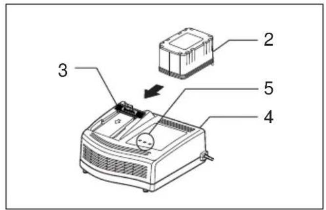
Switch action (Fig. 3)
CAUTION:
Before inserting the battery cartridge into the tool, always check to see that the switch trigger actuates properly and returns to the "OFF" position when released.
To start the tool, simply pull the trigger. Tool speed is increased by increasing pressure on the trigger. Release the trigger to stop.
Reversing switch action (Fig. 4)
CAUTION:
- Always check the direction of rotation before operation.
- Use the reversing switch only after the tool comes to a complete stop. Changing the direction of rotation before the tool stops may damage the tool.
- When not operating the tool, always set the reversing switch lever to the neutral position.
This tool has a reversing switch to change the direction of rotation. Depress the reversing switch lever from the A side for clockwise rotation or from the B side for counterclockwise rotation. When the switch lever is in the neutral position, the switch trigger cannot be pulled.
Selecting action mode
Rotation with hammering (Fig. 5)
For drilling in concrete, masonry, etc., depress the lock button and rotate the change lever so that the pointer points to the 📋 symbol. Use a tungsten-carbide tipped bit.
Rotation only (Fig.6)
For drilling in wood, metal or plastic materials, depress the lock button and rotate the change lever so that the pointer points to the ⬆ symbol. Use a twist drill bit or wood bit.
Hammering only (Fig.7)
For chipping, scaling or demolition operations, depress the lock button and rotate the change lever so that the pointer points to the symbol. Use a bull point, cold chisel, scaling chisel, etc.
CAUTION:
- Do not rotate the change lever when the tool is running. The tool will be damaged.
- To avoid rapid wear on the mode change mechanism, be sure that the change lever is always positively located in one of the three action mode positions.
Installing or removing bit
Important:
Always be sure that the tool is switched off and the battery cartridge is removed before installing or removing the bit.
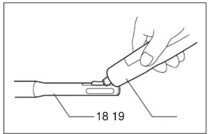
Clean the bit shank and apply the bit grease provided to it before installing the bit. (Fig. 8)
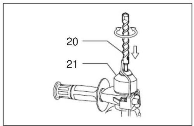
Insert the bit into the tool. Turn the bit and push it in until it engages. (Fig.9)
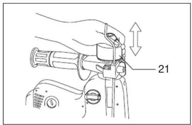
If the bit cannot be pushed in, remove the bit. Pull the chuck cover down a couple of times. Then insert the bit again. Turn the bit and push it in until it engages.
(Fig. 10)
After installing, always make sure that the bit is securely held in place by trying to pull it out.
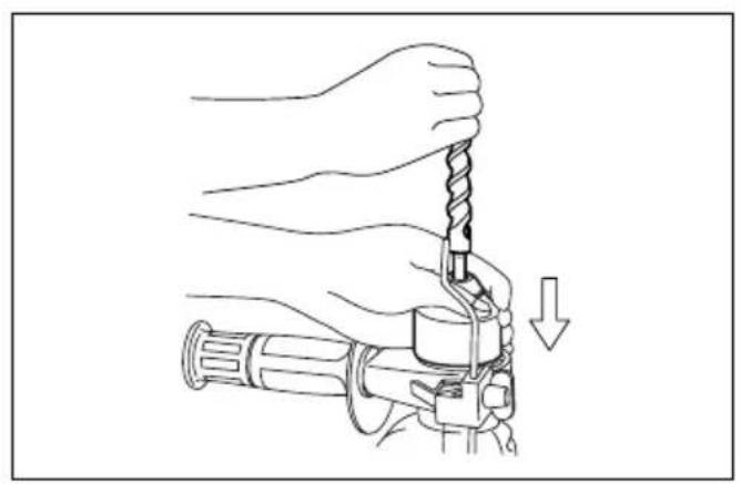
To remove the bit, pull the chuck cover down all the way and pull the bit out. (Fig. 11)
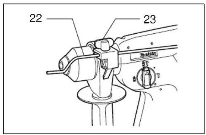
Depth gauge (Fig. 12)
The depth gauge is convenient for drilling holes of uniform depth. Loosen the clamp screw and adjust the depth gauge to the desired depth. After adjusting, tighten the clamp screw firmly.
NOTE:
The depth gauge cannot be used at the position where the depth gauge strikes against the gear housing/motor housing.
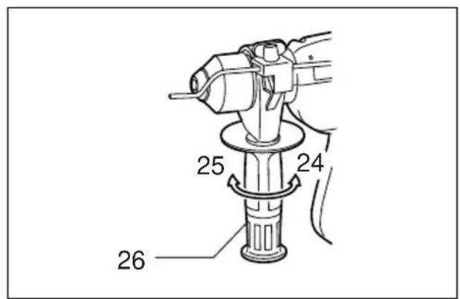
Side grip (Fig. 13)
CAUTION:
Always use the side grip to ensure operating safety when drilling in concrete, masonry, etc.
The side grip swings around to either side, allowing easy handling of the tool in any position. Loosen the side grip by turning it counterclockwise, swing it to the desired position and then tighten it by turning clockwise.
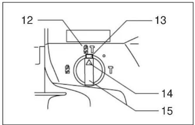
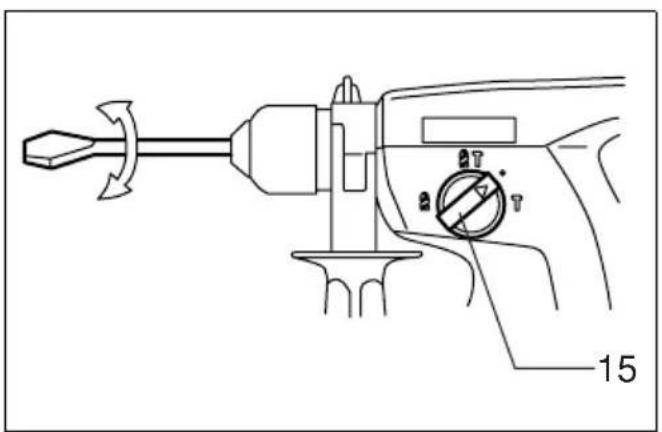
Bit angle
(when chipping, scaling or demolishing)
Important:
Always be sure that the tool is switched off and the battery cartridge is removed before changing the bit angle.
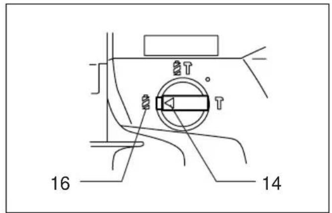
To change the bit angle, depress the lock button and rotate the change lever so that the pointer points to the ○ symbol. Turn the bit to the desired angle. (Fig.14)
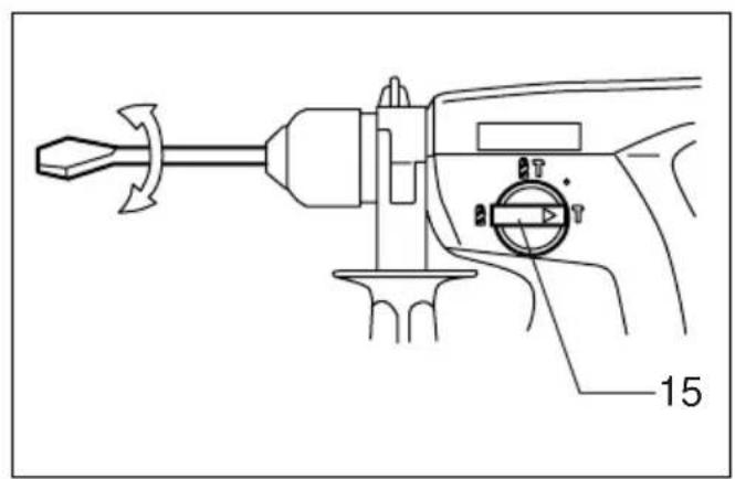
Depress the lock button and rotate the change lever so that the pointer points to the symbol. (Fig. 15)
Then make sure that the bit is securely held in place by turning it slightly.
Operation
CAUTION:
- Always insert the battery cartridge all the way until it locks in place. If you can see the red part on the upper side of the button, it is not locked completely. Insert it fully until the red part cannot be seen. If not, it may accidentally fall out of the tool, causing injury to you or someone around you.
- When operating overhead, always make sure the battery cartridge is locked securely so that it will not be fallen out of the tool. If not, it may accidentally fall out of the tool, causing injury to you or someone around you.
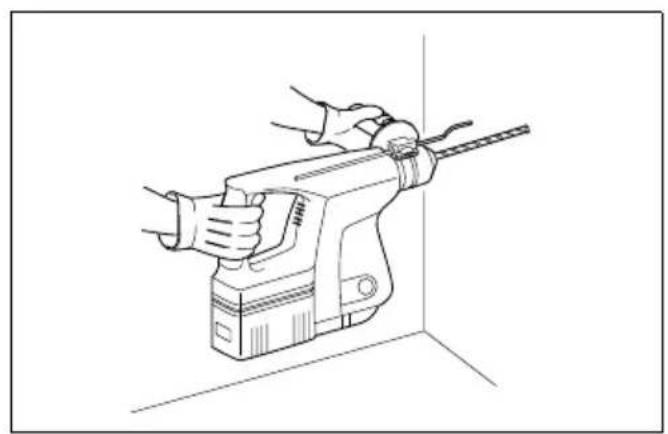
Hammer drilling operation (Fig. 16)
Set the change lever to the symbol. Position the bit at the location for the hole, then pull the trigger. Do not force the tool. Light pressure gives best results. Keep the tool in position and prevent it from slipping away from the hole.
Do not apply more pressure when the hole becomes clogged with chips or particles. Instead, run the tool at an idle, then remove from the hole. By repeating this several times, the hole will be cleaned out.
CAUTION:
- When the bit begins to break through concrete or if the bit strikes reinforcing rods embedded in concrete, the tool may react dangerously. Maintain good balance and safe footing while holding the tool firmly with both hands to prevent dangerous reaction.
Torque limiter
The torque limiter will actuate when a certain torque level is reached. The motor will disengage from the output shaft. When this happens, the bit will stop turning.
CAUTION:
As soon as the torque limiter actuates, switch off the tool immediately. This will help prevent premature wear of the tool.
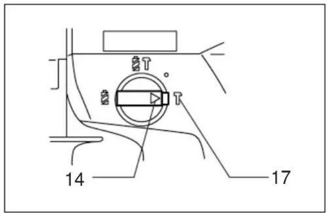
Chipping/Scaling/Demolition (Fig. 17)
Set the change lever to the symbol. Hold the tool firmly with both hands. Turn the tool on and apply slight pressure on the tool so that the tool will not bounce around, uncontrolled. Pressing very hard on the tool will not increase the efficiency.
Drilling operation (Fig. 18)
Use the optional drill chuck assembly. When installing it, refer to "Installing or removing drill bit" described on the previous page. You can drill up to 13 mm diameter in metal and up to 27 mm diameter in wood.
Set the change lever so that the pointer points to the symbol.
Use a cutting lubricant when drilling metals. The exception is brass which should be drilled dry.
CAUTION:
- Pressing excessively on the tool will not speed up the drilling. In fact, this excessive pressure will only serve to damage the tip of your bit, decrease the tool performance and shorten the service life of the tool.
- Never use “rotation with hammering” when the drill chuck assembly is installed on the tool. The drill chuck assembly may be damaged.
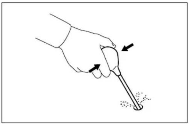
Blow-out bulb (Fig. 19)
Use the blow-out bulb to clean out the hole.
Dust cup (Fig. 20)
Use the dust cup to prevent dust from falling over the tool and on yourself when performing overhead drilling operations. Attach the dust cup to the bit. The size of bits which the dust cup can be attached to is as follows.
| Bit diameter (mm) | |
| Dust cup 5 6–14.5 | |
| Dust cup 9 12– 16 |
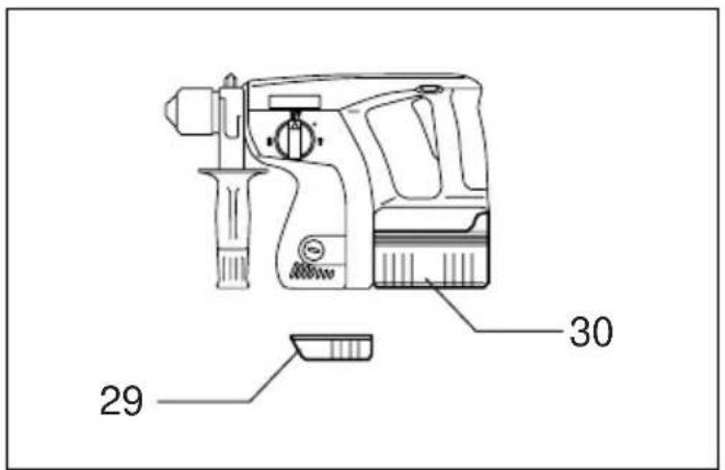
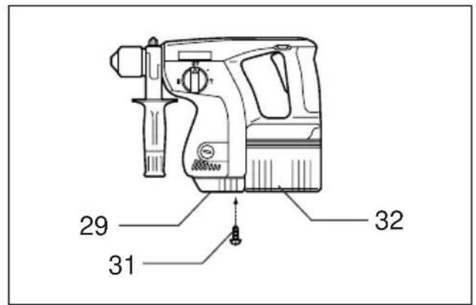
Foot
Remove the foot when you use the battery cartridge B2417.
This will help to place the tool steady. (Fig. 21)
Install the foot when you use the battery cartridge B2430.
This will help to place the tool steady. (Fig. 22)
MAINTENANCE
CAUTION:
Always be sure that the tool is switched off and the battery cartridge is removed before carrying out any work on the tool.
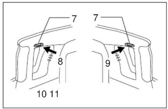
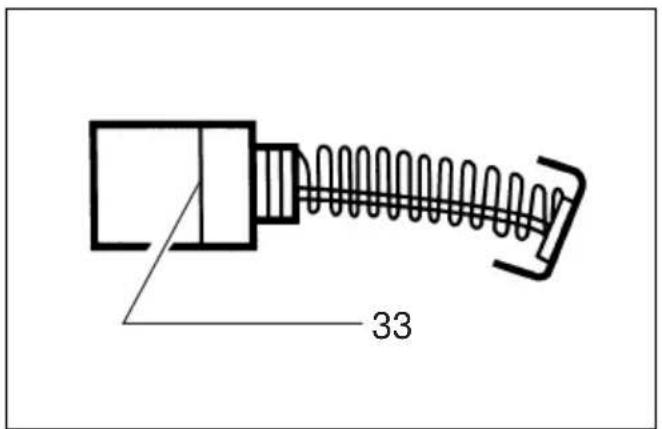
Replacement of carbon brushes (Fig. 23 & 24)
Remove and check the carbon brushes regularly. Replace when they wear down to the limit mark. Keep the carbon brushes clear and free to slip in the holders. Both carbon brushes should be replaced at the same time. Use only identical carbon brushes.
Use a screwdriver to remove the brush holder caps. Take out the worn carbon brushes, insert the new ones and secure the brush holder caps.
To maintain product safety and reliability, repairs, maintenance or adjustment should be carried out by a Makita Authorized Service Center.
Descriptif
Slagboring (Hammerboring) (Fig. 16)
These accessories or attachments are recommended for use with your Makita tool specified in this manual. The use of any other accessories or attachments might present a risk of injury to persons. The accessories or attachments should be used only in the proper and intended manner.
F ACCESSOIRES
ATTENTION:
natural_image
Line drawing of a pair of safety goggles (no text or symbols)ENGLISH
EC-DECLARATION OF CONFORMITY
We declare under our sole responsibility that this product is in compliance with the following standards or standardized documents,
EN50260, EN55014
in accordance with Council Directives, 89/336/EEC and 98/37/EC.
FRANÇAISE
DÉCLARATION DE CONFORMITÉ CE
EU-DEKLARATION OM KONFORMITET
Michigan Drive, Tongwell, Milton Keynes,
Bucks MK15 8JD, ENGLAND
ENGLISH
EC-DECLARATION OF CONFORMITY
We declare under our sole responsibility that this product is in compliance with the following standards or standardized documents,
in accordance with Council Directives, 73/23/EEC and 89/336/EC.
FRANÇAISE
DÉCLARATION DE CONFORMITÉ CE
EU-DEKLARATION OM KONFORMITET
Michigan Drive, Tongwell, Milton Keynes,
Bucks MK15 8JD, ENGLAND
ENGLISH
Noise and Vibration
The typical A-weighted noise levels are
sound pressure level: 89 dB (A)
sound power level: 102 dB (A)
– Wear ear protection. –
The typical weighted root mean square acceleration value is 9 m/s^2 .
FRANÇAISE
Bruit et vibrations

- SPECIFICATIONS
- Model BHR200
- Safety hints
- IMPORTANT SAFETY INSTRUCTIONS FOR CHARGER & BATTERY CARTRIDGE
- ADDITIONAL SAFETY RULES FOR CHARGER & BATTERY CARTRIDGE
- ADDITIONAL SAFETY RULES FOR TOOL
- SAVE THESE INSTRUCTIONS.
- OPERATING INSTRUCTIONS
- Installing or removing battery cartridge (Fig. 1)
- Charging (Fig. 2)
- Cooling system (DC24SA only)
- Conditioning charge (DC24SA only)
- Trickle charge (Maintenance charge)
- Tips for maintaining maximum battery life
- NOTE:
- Switch action (Fig. 3)
- CAUTION:
- Reversing switch action (Fig. 4)
- Selecting action mode
- Rotation with hammering (Fig. 5)
- Rotation only (Fig.6)
- Hammering only (Fig.7)
- Installing or removing bit
- (Fig. 10)
- Depth gauge (Fig. 12)
- Side grip (Fig. 13)
- Bit angle
- (when chipping, scaling or demolishing)
- Operation
- Hammer drilling operation (Fig. 16)
- Torque limiter
- Chipping/Scaling/Demolition (Fig. 17)
- Drilling operation (Fig. 18)
- Blow-out bulb (Fig. 19)
- Dust cup (Fig. 20)
- Foot
- MAINTENANCE
- Replacement of carbon brushes (Fig. 23 & 24)
- Slagboring (Hammerboring) (Fig. 16)
- F ACCESSOIRES
- ATTENTION:
- ENGLISH
- EC-DECLARATION OF CONFORMITY
- FRANÇAISE
- DÉCLARATION DE CONFORMITÉ CE
- EU-DEKLARATION OM KONFORMITET
- Noise and Vibration
- Bruit et vibrations
Brand : MAKITA
Model : BHR202RFX
Category : Drill