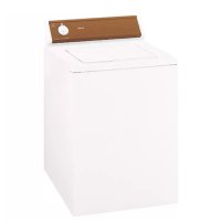
AWM 1081 EU - Washing machine HOTPOINT - Free user manual and instructions
Find the device manual for free AWM 1081 EU HOTPOINT in PDF.
| Product type | Washing machine |
| Brand | Hotpoint |
| Model | AWM 1081 EU |
| Dimensions (W x H x D) | 59.5 x 81.5 x 54.5 cm |
| Weight | Approximately 68 kg |
| Power supply | 230 V, 50 Hz |
| Wash capacity | 1 to 7 kg |
| Maximum spin speed | 1000 rpm |
| Energy class | A+ |
| Annual energy consumption | 201 kWh |
| Annual water consumption | 10623 L |
| Noise level (wash/spin) | 50 / 69 dB(A) |
| Wash programmes | 13 programmes (Cotton, Synthetics, Mix, Wool, Silk, etc.) |
| Special functions | Super wash, Super rinse, Easy iron, Delayed start |
| Settings | Temperature (cold to 90°C), Spin speed (0-1000 rpm) |
| Safety | Door lock, automatic stop, anti-unbalance system |
| Maintenance | Detergent drawer cleaning, self-cleaning pump, inlet hose check |
| Spare parts | Available from authorized after-sales service |
| Warranty | 2 years (standard) |
| Repairability | Contact authorized after-sales service for any repairs |
Frequently Asked Questions - AWM 1081 EU HOTPOINT
User questions about AWM 1081 EU HOTPOINT
0 question about this device. Answer the ones you know or ask your own.
Ask a new question about this device
Download the instructions for your Washing machine in PDF format for free! Find your manual AWM 1081 EU - HOTPOINT and take your electronic device back in hand. On this page are published all the documents necessary for the use of your device. AWM 1081 EU by HOTPOINT.
USER MANUAL AWM 1081 EU HOTPOINT
natural_image
Pure mechanical diagram of a circular component with internal channels and arrows, no text or symbols presentnatural_image
Line drawing of a washing machine with a circular button and a scroll wheel, showing a rotational arrow (no text or symbols)natural_image
Technical line drawings of two mechanical components: a hexagonal bolt and a flanged pin (no text or symbols)natural_image
Diagram of a mechanical valve or pump assembly with directional arrow indicating rotation (no text or symbols)natural_image
Simple line drawing of a pipe connection with a bulb above it (no text or symbols)natural_image
Simple line drawing of a box with a handle, no text or symbols presentA

natural_image
Line drawing of a front-loading washing machine with open lid and side panel (no text or symbols)B
natural_image
Line drawing of a washing machine with side panels and ventilation slots (no text or symbols)C
natural_image
Diagram of a washing machine with a door open, showing internal components and directional arrows (no text or symbols)D
natural_image
3D diagram of a rectangular box with a side panel and directional arrows indicating flow or movement (no text or symbols)E
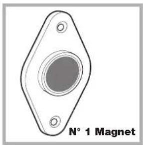
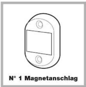
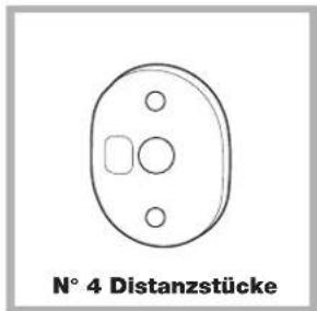
Accessori montaggio portina (Fig. 1-2-3-4-5).
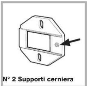
Fig. 1
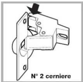
Fig. 2
natural_image
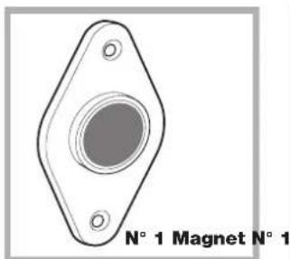
Technical drawing of a flange with a central circular feature and two mounting holes (no text or symbols)N° 1
1
Fig. 3 Fig. 4
natural_image
Simple line drawing of a cylindrical object labeled 'N° 1 Tassello in gomma' (no other text or symbols)Fig. 5
natural_image
Simple line drawing of a circular component with three holes and two internal square cutouts, labeled 'N° 4 Distanziali' below (no other text or symbols)Fig. 4/B
natural_image
Diagram of a mechanical component with directional arrows indicating movement or force (no text or symbols)Fig. 8 Fig. 9

natural_image
Pure technical line drawing of a mechanical component with no text or symbolsnatural_image
Hand inserting a USB into a device component (no text or symbols visible)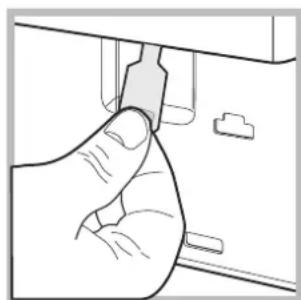
natural_image
Illustration of a hand inserting a component into a device (no text or symbols visible)Consumo in off-mode: 0,5 W
Consumo in Left-on: 8 W
Spie
Installation, 16-17-18-19
Unpacking and levelling
Connecting the electricity and water supplies
The first wash cycle
Technical data
Instructions for the fitter
Care and maintenance, 20
Cutting off the water or electricity supply
Cleaning the washing machine
Cleaning the detergent dispenser drawer
Caring for the door and drum of your appliance
Cleaning the pump
Checking the water inlet hose
AWM 1081
Precautions and tips, 21
General safety
Disposal
Opening the porthole door manually
Description of the washing machine and starting a wash cycle, 22-23
Control panel
Indicator lights
Starting a wash cycle
Wash cycles, 24
Table of wash cycles
Personalisation, 25
Setting the temperature
Setting the spin speed
Functions
Detergents and laundry, 26
Detergent dispenser drawer
Bleach cycle
Preparing the laundry
Garments requiring special care
Load balancing system
Troubleshooting, 27
Service, 28
GB
! This instruction manual should be kept in a safe place for future reference. If the washing machine is sold, transferred or moved, make sure that the instruction manual remains with the machine so that the new owner is able to familiarise himself/herself with its operation and features.
! Read these instructions carefully: they contain vital information relating to the safe installation and operation of the appliance.
Unpacking and levelling
Unpacking
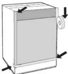
- Remove the washing machine from its packaging.
- Make sure that the washing machine has not been damaged during the transportation process. If it has been damaged, contact the retailer and do not proceed any further with the installation process.
natural_image
Technical diagram of a mechanical or electrical component with concentric circular and oval shapes, no visible text or symbols-
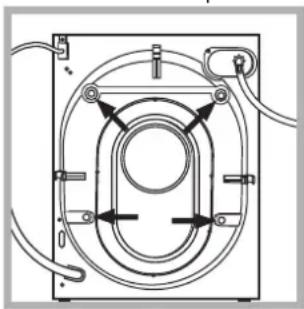
Remove the 4 protective screws (used during transportation) and the rubber washer with the corresponding spacer, located on the rear part of the appliance (see figure).
-
Close off the holes using the plastic plugs provided.
- Keep all the parts in a safe place: you will need them again if the washing machine needs to be moved to another location.
! Packaging materials should not be used as toys for children.
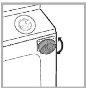
Levelling
- Install the washing machine on a flat sturdy floor, without resting it up against walls, furniture cabinets or anything else.
natural_image
Line drawing of a washing machine with a circular button and a scroll wheel, showing a rotational arrow (no text or symbols)- If the floor is not perfectly level, compensate for any unevenness by tightening or loosening the adjustable front feet (see figure); the angle of inclination, measured in relation to the worktop, must not exceed 2^ .
Levelling the machine correctly will provide it with stability, help to avoid vibrations and excessive noise and prevent it from shifting while it is operating. If it is placed on carpet or a rug, adjust the feet in such a way as to allow a sufficient ventilation space underneath the washing machine.
Connecting the electricity and water supplies
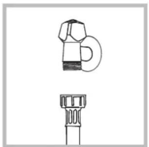
Connecting the water inlet hose
natural_image
Technical line drawing of a mechanical component with two views: top shows a cylindrical component, bottom shows a flanged base (no text or symbols)- Connect the supply pipe by screwing it to a cold water tap using a 34 gas threaded connection (see figure). Before performing the connection, allow the water to run freely until it is perfectly clear.
natural_image
Line drawing of a mechanical component with a valve and handle (no text or symbols)-
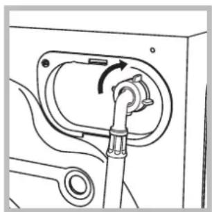
Connect the inlet hose to the washing machine by screwing it onto the corresponding water inlet of the appliance, which is situated on the top right-hand side of the rear part of the appliance (see figure).
-
Make sure that the hose is not folded over or bent.
! The water pressure at the tap must fall within the values indicated in the Technical details table (see next page).
! If the inlet hose is not long enough, contact a specialised shop or an authorised technician.
! Never use second-hand hoses.
! Use the ones supplied with the machine.
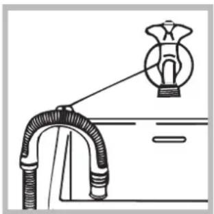
Connecting the drain hose

Connect the drain hose, without bending it, to a drainage duct or a wall drain located at a height between 65 and 100 cm from the floor;
natural_image
Diagram of a pipe connection with a bulb above it, no text or symbols presentalternatively, rest it on the side of a washbasin or bathtub, fastening the duct supplied to the tap (see figure). The free end of the hose should not be underwater.
! We advise against the use of hose extensions; if it is absolutely necessary, the extension must have the same diameter as the original hose and must not exceed 150 cm in length.
Electrical connections
Before plugging the appliance into the electricity socket, make sure that:
- the socket is earthed and complies with all applicable laws;
- the socket is able to withstand the maximum power load of the appliance as indicated in the Technical data table (see opposite);
- the power supply voltage falls within the values indicated in the Technical data table (see opposite);
- the socket is compatible with the plug of the washing machine. If this is not the case, replace the socket or the plug.
! The washing machine must not be installed outdoors, even in covered areas. It is extremely dangerous to leave the appliance exposed to rain, storms and other weather conditions.
! When the washing machine has been installed, the electricity socket must be within easy reach.
! Do not use extension cords or multiple sockets.
! The cable should not be bent or compressed.
! The power supply cable must only be replaced by authorised technicians.
Warning! The company shall not be held responsible in the event that these regulations are not respected.
The first wash cycle
Once the appliance has been installed, and before you use it for the first time, run a wash cycle with detergent and no laundry, using the wash cycle 2.
| Technical data | |
| Model | AWM 1081 |
| Dimensions | width 59.5 cmheight 81,5 cmdepth 54,5 cm |
| Capacity | from 1 to 7 kg |
| Electrical connections | please refer to the technical data plate fixed to the machine |
| Water connections | maximum pressure1 MPa (10 bar)minimum pressure0.05 MPa (0.5 bar)drum capacity 52 litres |
| Spin speed | up to 1000 rotations per minute |
| Test wash cycles in accordance with directives1061/20101015/2010 | Programme 2;Cotton Standard 60°C.Programme 3;Cotton Standard 40°C. |
| This appliance conforms to the following EC Directives:- 2004/108/EC (Electromagnetic Compatibility)- 2006/95/EC (Low Voltage)- 2012/19/EU | |
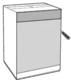
Instructions for the fitter
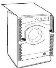
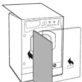
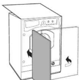
Mounting the wooden panel onto the door and inserting the machine into cabinets:
In the case where the machine must be shipped for final installation after the wooden panel has been mounted, we suggest leaving it in its original packaging. The packaging was designed to make it possible to mount the wooden panel onto the machine without removing it completely (see figures below).
The wooden panel that covers the face of the machine must not be less than 18 mm in thickness and can be hinged on either the right or left. For the sake of practicality when using the machine, we recommend that the panel be hinged on the same side as the door for the machine itself - the left.
natural_image
Simple line drawing of a rectangular box with a lid and a small object on the side (no text or symbols)A
natural_image
Line drawing of a front-loading washing machine with open lid and side panel (no text or symbols)B
natural_image
Line drawing of a washing machine with front panel and side door (no text or symbols)C
natural_image
Line drawing of a washing machine with a door open, showing internal components and directional arrows (no text or symbols)D
natural_image
Diagram of a rectangular box with a side panel and a roller, showing directional arrows (no text or symbols)E
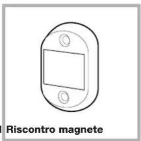
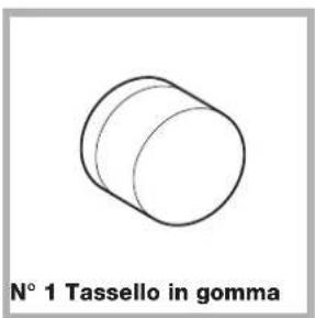
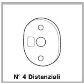
Door Mounting Accessories (Fig. 1-2-3-4-5).
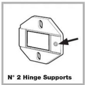
Fig. 1
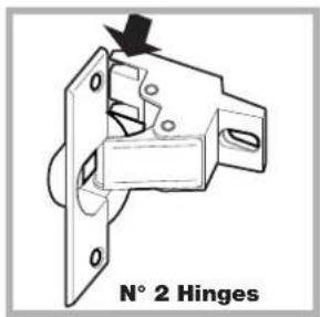
Fig. 2
natural_image
Technical drawing of a flange component with two mounting holes and a central circular feature (no text or symbols)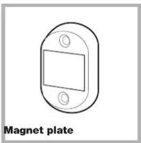
natural_image
Simple line drawing of a rectangular magnet plate with two mounting holes (no text or symbols)Fig. 3 Fig. 4
natural_image
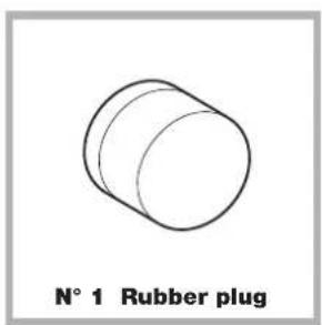
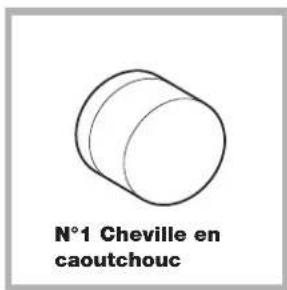
Simple line drawing of a cylindrical object labeled 'N° 1 Rubber plug' (no other text or symbols)Fig. 5
natural_image
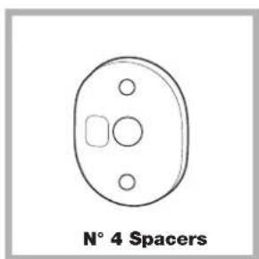
Simple line drawing of a circular device with three holes and a labeled number 'N° 4 Spacers' below (no other text or symbols)Fig. 4/B
- No. 6 type A self-threading screws, l = 13 mm.
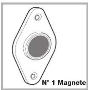
- No. 2 type B metric, countersunk screws, l =25; for fastening the magnet plate to the cabinet.
- No. 4 type C metric screws, l=15 mm; for mounting the hinge supports to the cabinet.
- No. 4 type D metric screws, l=7 mm; for mounting the hinges on the supports.
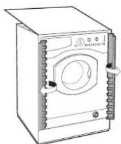
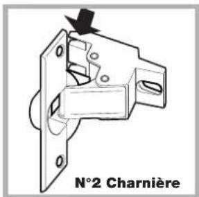
Mounting the Parts onto the Face of the Machine.
- Fit the hinge supports to the appliance front panel, positioning the hole marked with an arrow in fig. 1 so that it is on the inner side of the front panel. Fit a spacer (fig. 4/B) between the surfaces using type C screws.
- Fit the magnet plate at the top of the opposite side, using type B screws to fix two spacers (fig. 4/B) between the plate and the surface.
Using the Drilling Template.
- To trace the positions of the holes on the left-hand side of the panel, align the drilling template to the top left side of the panel using the lines traced on the extremities as a reference.
- To trace the positions of the holes on the right-hand side of the panel, align the drilling template to the top right side of the panel.
- Use an appropriately sized router to mill the holes for the two hinges, the rubber plug and the magnet.
Mounding the Parts onto the Wooden Panel (Door).
- Insert the hinges into the holes (the movable part of the hinge must be positioned facing away from the panel) and fasten them with the 4 type A screws.
- Insert the magnet into the top hole on the opposite side of the hinges and fasten it with the two type B screws.
- Insert the rubber plug into the bottom hole. The panel is now ready to be mounted onto the machine.
Mounting the Panel into the machine.
Insert the nib of the hinge (indicated by the arrow in fig. 2) into the hole for the hinge and push the panel towards the front of the machine. Fasten the two hinges with the type D screws.
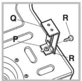
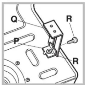
Fastening the plinth guide.
If the machine is installed at the end of a set of modular cabinets, mount either one or both of the guides for the base molding (as shown in fig. 8). Adjust them for depth based on the position of the base molding, and, if necessary, fasten the base to the guides (fig. 9).
This is how to assemble the plinth guide (fig. 8):
Fasten angle P using screw R, insert plinth guide Q into the special slot and once it is in the desired position, lock it in place using angle P and screw R.
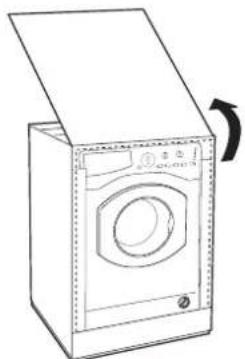
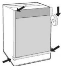
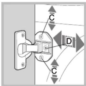
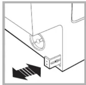
Inserting the machine into the Cabinet.
- Push the machine into the opening, aligning it with the cabinets (fig. 6).
- Regulate the adjustable feet to raise the machine to the appropriate height.
- To adjust the position of the wooden panel in both the vertical and horizontal directions, use the C and D screws, as shown in fig. 7.
Important: close the lower part of the appliance from by ensuring that the plinth rests against the floor.
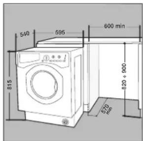
Fig. 6 Fig. 7

natural_image
Diagram of a mechanical or electrical component with directional arrows indicating movement (no text or symbols)Fig. 8 Fig. 9
Accessories provided for the height adjustment.
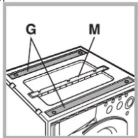
Fig. 10
The following can be found inside the polystyrene lid (fig. 10): 2 crossbars (G),
1 strip (M)
the following can be found
inside the appliance drum:
4 additional feet (H),
4 screws (I),
4 screws (R),
4 nuts (L),
2 plinth guides (Q)
Adjusting the appliance height.
The height of the appliance can be adjusted (from 815 mm to 835 mm), by turning the 4 feet.
Should you require the appliance to be placed higher than the above height, you need to use the following accessories to raise it to up to 870 mm: the two crossbars (G); the 4 feet (H); the 4 screws (I); the 4 nuts (L) then perform the following operations (fig. 11):
remove the 4 original feet, place a crossbar G at the front of the appliance, fastening it in place using screws I (screwing them in where the original feet were) then insert the new feet H. Repeat the same operation at the back of the appliance.
Now adjust feet H to raise or lower the appliance from 835 mm to 870 mm.
Once you have reached the desired height, lock nuts L onto crossbar G.
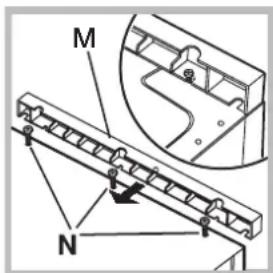
To adjust the appliance to a height between 870 mm and 900 mm, you need to mount strip M, adjusting feet H to the required height.
Insert the strip as follows:
loosen the three screws N situated at the front of the Top cover of the appliance, insert strip M as shown in fig. 12, then fasten screws N.
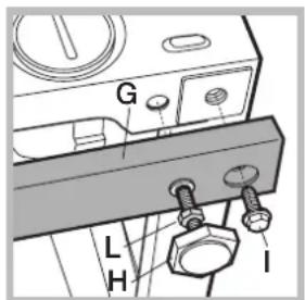
Fig. 11 Fig. 12
Cutting off the water and electricity supplies
- Turn off the water tap after every wash cycle. This will limit wear on the hydraulic system inside the washing machine and help to prevent leaks.
- Unplug the washing machine when cleaning it and during all maintenance work.
Cleaning the washing machine
The outer parts and rubber components of the appliance can be cleaned using a soft cloth soaked in lukewarm soapy water. Do not use solvents or abrasives.
Cleaning the detergent dispenser drawer
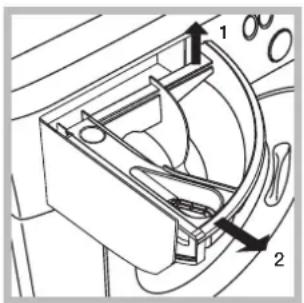
Remove the dispenser by raising it and pulling it out (see figure). Wash it under running water; this operation should be repeated frequently.
Caring for the door and drum of your appliance
• Always leave the porthole door ajar in order to prevent unpleasant odours from forming.
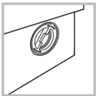
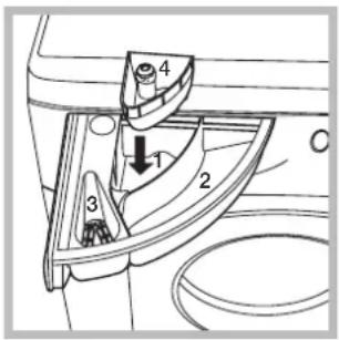
Cleaning the pump
The washing machine is fitted with a self-cleaning pump which does not require any maintenance. Sometimes, small items (such as coins or buttons) may fall into the pre-chamber which protects the pump, situated in its bottom part.
! Make sure the wash cycle has finished and unplug the appliance.
To access the pre-chamber:
natural_image
Pure technical line drawing of a mechanical component with no text or symbols-
unscrew the lid by rotating it anticlockwise (see figure): a little water may trickle out. This is perfectly normal;
-
clean the inside thoroughly;
- screw the lid back on.
Checking the water inlet hose
Check the inlet hose at least once a year. If there are any cracks, it should be replaced immediately: during the wash cycles, water pressure is very strong and a cracked hose could easily split open.
! Never use second-hand hoses.
! This washing machine was designed and constructed in accordance with international safety regulations. The following information is provided for safety reasons and must therefore be read carefully.
General safety
- This appliance was designed for domestic use only.
- This appliance can be used by children aged from 8 years and above and persons with reduced physical, sensory or mental capabilities or lack of experience and knowledge if they have been given supervision or instruction concerning use of the appliance in a safe way and understand the hazards involved. Children shall not play with the appliance. Cleaning and user maintenance shall not be made by children without supervision.
- Do not touch the machine when barefoot or with wet or damp hands or feet.
- Do not pull on the power supply cable when unplugging the appliance from the electricity socket. Hold the plug and pull.
- Do not open the detergent dispenser drawer while the machine is in operation.
- Do not touch the drained water as it may reach extremely high temperatures.
- Never force the porthole door. This could damage the safety lock mechanism designed to prevent accidental opening.
- If the appliance breaks down, do not under any circumstances access the internal mechanisms in an attempt to repair it yourself.
- Always keep children well away from the appliance while it is operating.
- The door can become quite hot during the wash cycle.
- If the appliance has to be moved, work in a group of two or three people and handle it with the utmost care. Never try to do this alone, because the appliance is very heavy.
- Before loading laundry into the washing machine, make sure the drum is empty.
Disposal
- Disposing of the packaging materials: observe local regulations so that the packaging may be re-used.
- The European Directive 2012/19/EU on Waste Electrical and Electronic Equipment, requires that old household electrical appliances must not be disposed of in the normal unsorted municipal waste stream. Old appliances must be collected separately in order to optimise the recovery and recycling of the materials they contain and reduce the impact on human health and the environment. The crossed out “wheeled bin” symbol on the product reminds you of
your obligation, that when you dispose of the appliance it must be separately collected.
Consumers should contact their local authority or retailer for information concerning the correct disposal of their old appliance.
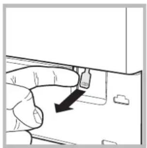
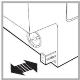
Opening the porthole door manually
In the event that it is not possible to open the porthole door due to a powercut, and if you wish to remove the laundry, proceed as follows:
- remove the plug from the electrical socket.
- make sure the water level inside the machine is lower than the door opening; if it is not, remove excess water using the drain hose, collecting it in a bucket.
- pull outwards using the tab as indicated in the figure, until the plastic tie-rod is freed from its stop position; pull downwards and open the door at the same time.
natural_image
Hand inserting a USB into a device component (no text or symbols visible)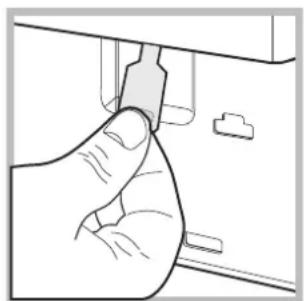
natural_image
Hand holding a small object near a window (no text or symbols visible)Description of the washing machine and starting a wash cycle
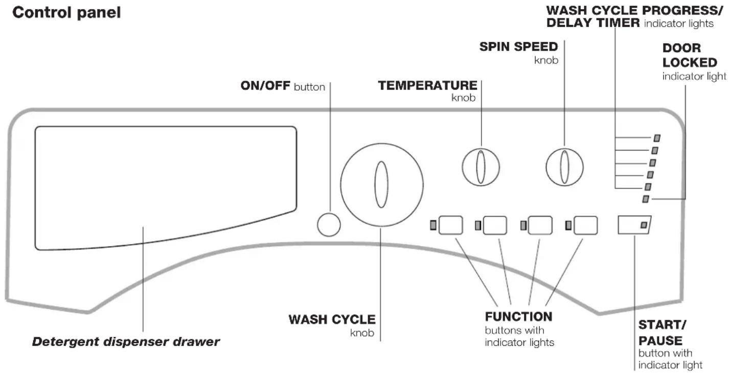
Detergent dispenser drawer: used to dispense detergents and washing additives (see "Detergents and laundry").
ON/OFF button: switches the washing machine on and off.
WASH CYCLE knob: programmes the wash cycles. During the wash cycle, the knob does not move.
FUNCTION buttons with indicator light: used to select the available functions. The indicator light corresponding to the selected function will remain lit.
TEMPERATURE knob: sets the temperature or the cold wash cycle (see "Personalisation").
SPIN SPEED knob: sets the spin speed or exclude the spin cycle completely (see "Personalisation").
WASH CYCLE PROGRESS/DELAY TIMER indicator
lights: used to monitor the progress of the wash cycle. The illuminated indicator light shows which phase is in progress.
If the Delay Timer function has been set, the time remaining until the wash cycle starts will be indicated (see next page).
DOOR LOCKED indicator light: indicates whether the door may be opened or not (see next page).
START/PAUSE button with indicator light: starts or temporarily interrupts the wash cycles.
N.B. To pause the wash cycle in progress, press this button; the corresponding indicator light will flash orange, while the indicator light for the current wash cycle phase will remain lit in a fixed manner. If the DOOR LOCKED indicator light is switched off, the door may be opened. To start the wash cycle from the point at which it was interrupted, press this button again.
Standby mode
This washing machine, in compliance with new energy saving regulations, is fitted with an automatic standby system which is enabled after about 30 minutes if no activity is detected. Press the ON-OFF button briefly and wait for the machine to start up again.
Consumption in off-mode: 0,5 W
Consumption in Left-on: 8 W
Indicator lights
The indicator lights provide important information. This is what they can tell you:
Delayed start
If the DELAY TIMER function has been activated (see "Personalisation"), after the wash cycle has been started the indicator light corresponding to the selected delay period will begin to flash:
As time passes, the remaining delay will be displayed and the corresponding indicator light will flash:
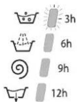
Once the set delay has elapsed, the flashing indicator light will switch off and the selected wash cycle will begin.
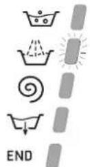
Wash cycle phase indicator lights
Once the desired wash cycle has been selected and has begun, the indicator lights switch on one by one to indicate which phase of the cycle is currently in progress.
Wash
Rinse
Spin
Drain
End of wash cycle
Function buttons and corresponding indicator lights
When a function is selected, the corresponding indicator light will illuminate.
If the selected function is not compatible with the programmed wash cycle, the corresponding indicator light will flash and the function will not be activated.
If a function which is incompatible with another function selected previously, only the most recent selection will remain active.
- Door locked indicator light
If this indicator light is on, the appliance door is locked to prevent it from being opened accidentally; to avoid any damage, wait for the indicator light to switch off before you open the appliance door.
N.B. If the DELAY TIMER function is activated, the door cannot be opened; pause the machine by pressing the START/PAUSE button if you wish to open it.
! If the START/PAUSE indicator light (orange) flashes rapidly at the same time as the function indicator light, this indicates a problem has occurred (see "Troubleshooting").
Starting a wash cycle
-
Turn the washing machine on by pressing the ON/OFF button. All the indicator lights will turn on for a few seconds, then only the indicator lights relative to the selected programme settings will remain lit and the START/PAUSE indicator light will flash.
-
Load the laundry and close the door.
-
Set the WASH CYCLE knob to the desired programme.
-
Set the washing temperature (see "Personalisation").
-
Set the spin speed (see "Personalisation").
-
Measure out the detergent and washing additives (see "Detergents and laundry").
-
Select the desired functions.
-
Start the wash cycle by pressing the START/PAUSE button and the corresponding indicator light will remain lit in a fixed manner, in green. To cancel the set wash cycle, pause the machine by pressing the START/PAUSE button and select a new cycle.
-
At the end of the wash cycle the END indicator light will switch on. The DOOR LOCKED indicator light will switch off, indicating that the door may be opened. Take out your laundry and leave the appliance door ajar to make sure the drum dries completely. Switch the washing machine off by pressing the ON/OFF button.
Table of wash cycles
| Wash cycles | Description of the wash cycle | Max. temp. (°C) | Max. speed (rpm) | Detergents | Max. load (kg) | Residual dampness% | Energy consumptionkWh | Total water It | Cycle duration | |||
| Prewash | Bleach | Wash | Fabric softener | |||||||||
| 1 | Cotton + Prewash: extremely soiled whites. | 90° 1000 | ● | - | ● | ● | 7 62 | 2,21 | 78 1 | 70' | ||
| 2 | <80°C Cotton Standard 60° (1): heavily soiled whites and resistant colours | 60° (Max.90°) | 1000 - | ● | ● | 7 62 | 1,13 | 52,5 | 180' | |||
| 3 | <40°C Cotton Standard 40° (2): lightly soiled resistant and delicate colours. | 40° 1000 - - | ● | ● | 7 62 | 1,00 | 75 1 | 70' | ||||
| 4 | Cotton Standard 20°: lightly soiled resistant and delicate colours. | 20° 1000 - - | ● | ● | 7 - | - | 170' | |||||
| 5 | Synthetics: heavily soiled resistant colours. | 60° | 800 | -- | ● | ● | 3,5 | 44 0 | 93 4 | 7 115' | ||
| 5 | Synthetics (3): lightly soiled resistant colours. | 40° | 800 | -- | ● | ● | 3,5 | 44 0 | 57 4 | 6 100' | ||
| 6 | Mix 30': to refresh lightly soiled garments quickly (not suitable for wool, silk and clothes which require washing by hand). | 30° 800 | -- | ● | ● | 3 71 | 0,15 | 35 | 30' | |||
| 7 | Mix 15': to refresh lightly soiled garments quickly (not suitable for wool, silk and clothes which require washing by hand). | 30° 800 | -- | ● | ● | 1,5 | 71 0 | 19 3 | 1 15' | |||
| 8 | Sanitizing cycle: extremely soiled whites. | 90° 1000 - | ● | ● | ● | 7 - | - | 190' | ||||
| 9 | Goodnigt cycle: lightly soiled delicate colours. | 40° 800 | -- | ● | ● | 4 - | - | 290' | ||||
| 10 | Baby cycle: heavily soiled delicate colours. | 40° 800 | -- | ● | ● | 2 - | - | 120' | ||||
| 11 | Shirts | 40° 600 | -- | ● | ● | 2 - | - | 80' | ||||
| 12 | Silk/Curtains: for garments in silk and viscose, lingerie. | 30° | 0 | -- | ● | ● | 1 - | - | 55' | |||
| 13 | Wool: for wool, cashmere, etc. | 40° 800 | -- | ● | ● | 1,5 | -- | 70' | ||||
| A | Rinse | - | 1000 - | -- | ● | 7 - | - | 36' | ||||
| B | Spin | - | 1000 - | - | -7 | - | - | 16' | ||||
| C | Drain | - | 0 | - | - | - | - | 7 | - | - | - | 2' |
The length of cycle shown on the display or in this booklet is an estimation only and is calculated assuming standard working conditions. The actual duration can vary according to factors such as water temperature and pressure, the amount of detergent used, the amount and type of load inserted, load balancing and any wash options selected.
1) Test wash cycle in compliance with directive 1061/2010: set wash cycle 2 with a temperature of 60°C.
This cycle is designed for cotton loads with a normal soil level and is the most efficient in terms of both electricity and water consumption; it should be used for garments which can be washed at 60°C. The actual washing temperature may differ from the indicated value.
2) Test wash cycle in compliance with directive 1061/2010: set wash cycle 3 with a temperature of 40°C.
This cycle is designed for cotton loads with a normal soil level and is the most efficient in terms of both electricity and water consumption; it should be used for garments which can be washed at 40°C. The actual washing temperature may differ from the indicated value.
For all Test Institutes:
2) Long wash cycle for cottons: set wash cycle 3 with a temperature of 40°C.
3) Long wash cycle for synthetics: set wash cycle 5 with a temperature of 40°C.
Cotton Standard 20° (wash cycle 4). Ideal for lightly soiled cotton loads. The effective performance levels achieved at cold temperatures, which are comparable to washing at 40°, are guaranteed by a mechanical action which operates at varying speed, with repeated and frequent peaks.
Mix 30' (wash cycle 6) this wash cycle was designed to wash lightly soiled garments quickly: it lasts just 30 minutes and therefore saves both energy and time. By selecting this wash cycle (6 at 30°C), it is possible to wash different fabrics together (except for wool and silk items), with a maximum load of 3 kg.
Mix 15' (wash cycle 7) this wash cycle was designed to wash lightly soiled garments quickly: it lasts just 15 minutes and therefore saves both energy and time. By selecting this wash cycle (7 at 30^ ), it is possible to wash different fabrics together (except for wool and silk items), with a maximum load of 1.5kg .
Sanitizing cycle (wash cycle 8). A high-temperature hygienic wash cycle (over 60°C) which requires the use of bleach. Pour the bleach, the detergent and the additives into the relevant compartments (see paragraph entitled “Detergent dispenser drawer”).
Goodnigt cycle (wash cycle 9). This is a silent cycle which can be run at night, when the electricity prices are lower. The wash cycle is designed for cottons and synthetics. At the end of the cycle the machine stops while there is still water in the drum; to spin and drain the laundry press the START/PAUSE button; alternatively the machine will perform the spin cycle and drain the water automatically after 8 hours.
Baby cycle (wash cycle 10). This wash cycle can be used to remove the soiling typically caused by babies, while ensuring that all detergent is removed from nappies in order to prevent the delicate skin of babies from suffering allergies. The cycle has been designed to reduce the amount of bacteria by using a greater quantity of water and optimising the effect of special disinfecting additives added to the detergent.
At the end of the wash cycle, the machine will slowly rotate the drum to prevent the formation of creases; to end the cycle press the START/PAUSE button.
Setting the temperature
Turn the TEMPERATURE knob to set the wash temperature (see Table of wash cycles).
The temperature may be lowered, or even set to a cold wash ( 12 ) The washing machine will automatically prevent you from selecting a temperature which is higher than the maximum value set for each wash cycle.
! Exception: if the 2 programme is selected, the temperature can be increased up to a value of 90°C.
Setting the spin speed
Turn the SPIN SPEED knob to set the spin speed for the selected wash cycle.
The maximum spin speeds available for each wash cycle are as follows:
Wash cycles Maximum spin speed
Cottons 1000 rpm
Synthetics 800 rpm
Wool 800 rpm
Silk drain only
The spin speed may be lowered, or the spin cycle can be excluded altogether by selecting the symbol ⚙
The washing machine will automatically prevent you from selecting a spin speed which is higher than the maximum speed set for each wash cycle.
Functions
The various wash functions available with this washing machine will help to achieve the desired results, every time.
To activate the functions:
- Press the button corresponding to the desired function;
- the function is enabled when the corresponding indicator light is illuminated.
Note: If the indicator light flashes rapidly, this signals that this particular function may not be selected in conjunction with the selected wash cycle.

Super Wash
Because a greater quantity of water is used in the initial phase of the cycle, and because of the increased cycle duration, this function offers a high-performance wash.
! This function may not be used in conjunction with wash cycles 1, 6, 7, 8, 12, 13, B, C.

Extra rinse
By selecting this function, the efficiency of the rinse is increased and optimal detergent removal is guaranteed. It is particularly useful for sensitive skin.
! This function may not be used in conjunction with wash cycles 6, 7, B, C.
Easy iron
By selecting this function, the wash and spin cycles will be modified in order to reduce the formation of creases. At the end of the cycle the washing machine will perform slow rotations of the drum; the EASY IRON and START/PAUSE indicator lights will flash (orange) and the END phase will remain lit in a fixed manner. To end the cycle, press the START/PAUSE button or the EASY IRON button.
For the Silk wash cycle, the machine will end the cycle while the laundry is soaking, the EASY IRON and START/PAUSE indicator lights will flash (orange) and the RINSE phase will remain lit in a fixed manner. To drain the water so that the laundry may be removed, press the START/PAUSE button or the EASY IRON button.
! This function may not be used in conjunction with wash cycles 6, 7, 8, 9, 10, 13, A, B, C.
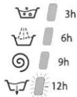
Delay timer
This timer delays the start time of the wash cycle by up to 12 hours.
Press the button repeatedly until the indicator light corresponding to the desired delay time switches on. The fifth time the button is pressed, the function will be disabled.
N.B. Once you have pressed the START/PAUSE button, the delay time may only be decreased if you wish to modify it.
! This option is enabled with all programmes.
Detergent dispenser drawer
Good washing results also depend on the correct dose of detergent: adding too much detergent will not necessarily result in a more efficient wash, and may in fact cause build up on the inside of your appliance and contribute to environmental pollution.
! Use powder detergent for white cotton garments, for pre-washing, and for washing at temperatures over 60°C.
! Follow the instructions given on the detergent packaging.
! Do not use hand washing detergents because these create too much foam.
Open the detergent dispenser drawer and pour in the detergent or washing additive, as follows.
compartment 1: Pre-wash detergent (powder)
Before pouring in the detergent, make sure that extra compartment 4 has been removed.
compartment 2: Detergent for the wash cycle (powder or liquid)
Liquid detergent should only be poured in immediately prior to the start of the wash cycle.
compartment 3: Additives (fabric softeners, etc.)
The fabric softener should not overflow the grid.
extra compartment 4: Bleach
Bleach cycle
Bleaching may only be performed in conjunction with wash cycle 8.
Pour the bleach into extra compartment 4; pour the detergent and softener into the corresponding compartments, then select one of the abovementioned wash cycles.
This option is recommended only for very soiled cotton garments.
Preparing the laundry
- Divide the laundry according to:
- the type of fabric/the symbol on the label
- the colours: separate coloured garments from whites.
- Empty all garment pockets and check the buttons.
- Do not exceed the listed values, which refer to the weight of the laundry when dry: see "Table of wash cycles".
How much does your laundry weigh?
1 sheet 400-500 g
1 pillow case 150-200 g
1 tablecloth 400-500 g
1 bathrobe 900-1200 g
1 towel 150-250 g
Garments requiring special care
Shirts: use special wash cycle 11 to wash shirts in various fabrics and colours.
It guarantees maximum care is taken of the garments and minimises the formation of creases.
Silk: use special wash cycle 12 to wash all silk garments. We recommend the use of special detergent which has been designed to wash delicate clothes.
Curtains: fold curtains and place them in a pillow case or mesh bag. Use wash cycle 12.
Wool: the wool wash cycle on this Hotpoint-Ariston machine has been tested and approved by The Woolmark Company for washing wool garments labelled as hand washable provided that the garments are washed according to the instructions on the garment label and those issued by the manufacturer of this washing machine. Hotpoint-Ariston is the first washing machine brand to be approved by The Woolmark Company for Apparel Care- Platinum for its washing performance and consumption of energy and
water. (M1126)

Load balancing system
Before every spin cycle, to avoid excessive vibrations and to distribute the load in a uniform manner, the drum rotates continuously at a speed which is slightly greater than the washing rotation speed. If, after several attempts, the load is not balanced correctly, the machine spins at a reduced spin speed. If the load is excessively unbalanced, the washing machine performs the distribution process instead of spinning. To encourage improved load distribution and balance, we recommend small and large garments are mixed in the load.
Your washing machine could fail to work. Before contacting the Technical Assistance Centre (see “Assistance”), make sure that the problem cannot be not solved easily using the following list.
Problem:
The washing machine does not switch on.
The wash cycle does not start.
The washing machine does not take in water (the indicator light for the first wash cycle stage flashes rapidly).
The washing machine continuously takes in and drains water.
The washing machine does not drain or spin.
The washing machine vibrates a lot during the spin cycle.
The washing machine leaks.
The START/PAUSE indicator light (orange) and the function indicator lights flash rapidly.
There is too much foam.
Possible causes / Solutions:
- The appliance is not plugged into the socket fully, or is not making contact.
• There is no power in the house.
- The washing machine door is not closed properly.
- The ON/OFF button has not been pressed.
- The START/PAUSE button has not been pressed.
- The water tap has not been opened.
- A delayed start has been set (see "Personalisation").
- The water inlet hose is not connected to the tap.
- The hose is bent.
- The water tap has not been opened.
• There is no water supply in the house.
• The pressure is too low.
- The START/PAUSE button has not been pressed.
- The drain hose is not fitted at a height between 65 and 100 cm from the floor (see "Installation").
- The free end of the hose is under water (see "Installation").
- The wall drainage system is not fitted with a breather pipe.
If the problem persists even after these checks, turn off the water tap, switch the appliance off and contact the Assistance Service. If the dwelling is on one of the upper floors of a building, there may be problems relating to water drainage, causing the washing machine to fill with water and drain continuously. Special anti-draining valves are available in shops and help to avoid this inconvenience.
- The wash cycle does not include draining: some wash cycles require the drain phase to be started manually.
- The EASY IRON function has been activated: To complete the wash cycle, press the START/PAUSE button ("Personalisation").
- The drain hose is bent (see "Installation").
- The drainage duct is clogged.
- The drum was not unlocked correctly during installation (see "Installation").
- The washing machine is not level (see "Installation").
- The washing machine is trapped between cabinets and walls (see "Installation").
- The water inlet hose is not screwed on properly (see "Installation").
- The detergent dispenser drawer is blocked (for cleaning instructions, see "Care and maintenance").
- The drain hose is not fixed properly (see "Installation").
- Switch off the machine and unplug it, wait for approximately 1 minute and then switch it back on again.
If the problem persists, contact the Technical Assistance Service.
- The detergent is not suitable for machine washing (it should display the text "for washing machines" or "hand and machine wash", or the like).
- Too much detergent was used.
Before calling for Assistance:
- Check whether you can solve the problem alone (see "Troubleshooting");
- Restart the programme to check whether the problem has been solved;
- If this is not the case, contact an authorised Technical Assistance Centre using the telephone number provided on the guarantee certificate.
! Always request the assistance of authorised technicians.
Have the following information to hand:
• the type of problem;
• the appliance model (Mod.);
• the serial number (S/N).
This information can be found on the data plate applied to the rear of the washing machine, and can also be found on the front of the appliance by opening the door.
COMMISSION DELEGATED REGULATION (EU) No 1061/2010
| Brand | HOTPOINT/ARISTON |
| Model | AWM 1081 EU |
| Rated capacity in kg of cotton | 7.0 |
| Energy efficiency class on a scale from A+++ (low consumption) to G (high consumption) | A+ |
| Energy consumption per year in kWh 1) | 201.0 |
| Energy consumption of the standard 60 °C cotton programme at full load in kWh 2) | 1.133 |
| Energy consumption of the standard 60 °C cotton programme at partial load in kWh 2) | 0.712 |
| Energy consumption of the standard 40 °C cotton programme at partial load in kWh 2) | 0.677 |
| Power consumption of the off-mode in W | 0.5 |
| Power consumption of the left-on mode in W | 8.0 |
| Water consumption per year in litres 3) | 10623 |
| Spin-drying efficacy class on a scale from G (minimum efficacy) to A (maximum efficacy) | C |
| Maximum spin speed attained 4) | 1000 |
| Remaining moisture content 5) | 62% |
| Programme time of the "standard 60 °C cotton" at full load in minutes | 180 |
| Programme time of the "standard 60 °C cotton" at partial load in minutes | 150 |
| Programme time of the "standard 40°C cotton" at partial load in minutes | 145 |
| Duration of the left-on mode in minutes | 30 |
| Noise in dB(A) re 1 pW washing 6) | 50 |
| Noise in dB(A) re 1 pW spinning 6) | 69 |
1) The "standard 60°C cotton" at full and partial load and the "standard 40°C cotton" at partial load are the standard washing programmes to which the information in the label and the fiche relates. Standard 60°C cotton and standard 40°C cotton are suitable to clean normally soiled cotton laundry and are the most efficient programmes in terms of combined energy and water consumption. Partial load is half the rated load.
2) Based on 220 standard washing cycles for cotton programmes at 60°C and 40°C at full and partial load, and the consumption of the low-power modes. Actual energy consumption will depend on how the appliance is used.
3) Based on 220 standard washing cycles for cotton programmes at 60°C and 40°C at full and partial load. Actual water consumption will depend on how the appliance is used.
4) For the standard 60 °C at full and partial load or the 40°C at partial whichever is lower.
5) Attained for 60 °C cotton at full and partial load or the 40°C at partial whichever is higher.
6) Based on washing and spinning phases for the standard 60°C cotton programme at full load.

Français
Sommaire
Installation, 30-31-32-33
natural_image
Pure technical diagram of a mechanical or electrical component with no visible text, numbers, or symbols.natural_image
Line drawing of a washing machine with a circular button and a scroll wheel, showing a rotational arrow (no text or symbols)natural_image
Technical line drawings of two mechanical components: a hexagonal bolt and a flanged base (no text or symbols)natural_image
Line drawing of a mechanical component with a valve and handle (no text or symbols)natural_image
Diagram of a pipe connection with a bulb above it, no text or symbols presentFig. 1
natural_image
Technical drawing of a mechanical flange component with bolt holes and central bore (no text or symbols)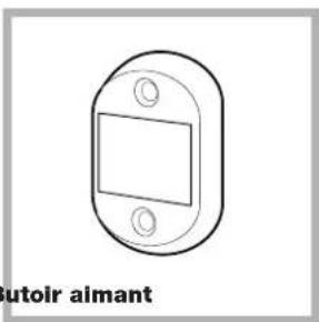
natural_image
Technical line drawing of a mechanical component with rounded corners and a central square (no text or symbols)Butoir aimant
Fig. 3 Fig. 4
natural_image
Simple line drawing of a circular switch or dial with three holes and two internal components, labeled 'N°4 Cales' below (no other text or symbols)Fig. 4/B
Fig. 6 Fig. 7
natural_image
Pure technical diagram showing a pipe connection with directional arrows, no text or symbols presentFig. 8 Fig. 9
natural_image
Pure technical line drawing of a mechanical component with no text or symbolsnatural_image
Hand holding a device with a black arrow pointing to a component (no text or symbols visible)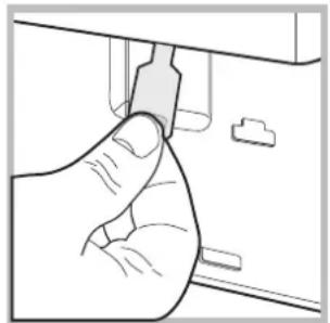
natural_image
Hand holding a small electronic component, no visible text or symbolsbac 3: Additifs (assouplissant, etc.)
Causes / Solutions possibles:
FR
Installation 44-45-46-47
natural_image
Pure technical diagram of a mechanical or electrical component with no visible text, numbers, or symbols.natural_image
Line drawing of a washing machine with a circular button and a scroll wheel (no text or symbols)natural_image
Technical line drawing of a pipe fitting with two views: top shows a flanged cap and ring, bottom shows a flanged bolt (no text or symbols)natural_image
Line drawing of a mechanical component with a valve and handle (no text or symbols)natural_image
Simple line drawing of a pipe connection with a bulb above it (no text or symbols)natural_image
Mechanical component diagram labeled N° 2 Scharnier, showing a bracket with mounting holes and a downward arrow (no text or symbols on the diagram itself)Abb. 2
natural_image
Technical drawing of a flange with a circular recess and two mounting holes (no text or symbols)Abb. 3 Abb. 4
natural_image
Simple line drawing of a cylindrical object labeled 'N° 1 Gummidübel' (no other text or symbols)Abb. 5
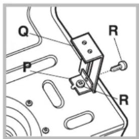
Abb. 8
natural_image
Diagram showing a mechanical component with a circular component and directional arrows indicating motion (no text or symbols)Abb. 9
natural_image
Pure technical line drawing of a mechanical component with no text or symbolsnatural_image
Hand holding a device with a black arrow pointing to a component (no text or symbols visible)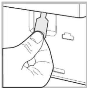
natural_image
Hand inserting a plug into a device (no text or symbols visible)6) Based on washing and spinning phases for the standard 60°C cotton programme at full load.