
N145 Automatic Premium LCD - Refrigerator THETFORD - Free user manual and instructions
Find the device manual for free N145 Automatic Premium LCD THETFORD in PDF.

| Product type | Absorption refrigerator for caravans and motorhomes |
| Brand | Thetford |
| Model | N145 Automatic Premium LCD |
| Category | C11 (EN 1749) - Gas appliance requiring isolated installation |
| Power supply | 230 V AC (50/60 Hz) and 12 V DC |
| Gas supply | Butane/Propane (G30/G31) at 28-30/37 mbar |
| Dimensions (H x W x D) including door | approx. 1450 x 525 x 600 mm |
| Net weight | approx. 35 kg |
| Gross volume (including freezer) | approx. 145 L |
| Usable volume (including freezer) | approx. 135 L |
| Freezer volume | approx. 12 L |
| Ignition type | Automatic via LCD control panel |
| Main functions | Automatic energy source selection (230 V, 12 V, gas) |
| Display | LCD screen |
| Installation | Must be installed in a compartment isolated from the living area |
| Ventilation | Requires two ventilation grilles (lower and upper) |
| Gas connection | Must be carried out by a certified professional |
| Electrical connection | Must comply with EN 60335-1 |
| Safety | Gas safety device (shut-off in case of flame failure) |
| Maintenance | Regularly clean the ventilation grilles, check the seals |
| Repairability | Spare parts available from Thetford |
| Use | Caravans and motorhomes only |
Frequently Asked Questions - N145 Automatic Premium LCD THETFORD
User questions about N145 Automatic Premium LCD THETFORD
0 question about this device. Answer the ones you know or ask your own.
Ask a new question about this device
Download the instructions for your Refrigerator in PDF format for free! Find your manual N145 Automatic Premium LCD - THETFORD and take your electronic device back in hand. On this page are published all the documents necessary for the use of your device. N145 Automatic Premium LCD by THETFORD.
USER MANUAL N145 Automatic Premium LCD THETFORD
Thetford Refrigerators (After Market)

FIGURES FOR INSTALLATION 2
UK Installation 11
FR Installation 19
DE Einbau 27
ES Montaje 35
NL Installatie 41
IT Installazione 50
SE Montering 60
| A | B | C | D | E | F | G | H | I | J |
| Model | Dimensions H x W x D (mm) Depth incl. door | Gross volume incl. freezer (L) | Net volume incl. freezer (L) | Volume freezer (L) | Input * (kWh/24h) | Input * (gr./24h) | Net weight (kg) | Operation Ignition | |
| N80-N10F01x1P | 821 x 486 x 543 | 81 | 75 | 10 | 2.5 | 300 | 22 | Manual Energy Selection | Piezo (Manual) |
| N100-N31G02x6E | 821 x 525 x 543 | 97 | 91 | 11 | 2.8 | 330 | 29 | Electric Energy Selection | Electric |
| N145-N51H06x6A | 1245 x 525 x 543 | 141 | 138 | 23 | 4.0 | 420 | 38 | Smart Energy Selection | Automatic |
| N180-N60H09x6A | 1245 x 525 x 603 | 180 | 175 | 11 | 3.7 | 400 | 39 | Smart Energy Selection | Automatic |
| A | B | C | D | E | F | G | H | I | J |
| Model | Measurements H x B x D (mm) depth incl. door | Gross volume incl. freezer (L) | Net volume incl. freezer (L) | Volume freezer (L) | Input ** (kWh/24h) | Input ** (gr./24h) | Net weight (kg) | Operation | Ignition |
6.
7.
8.
11
Combustions seal
N100/N180
N80
12
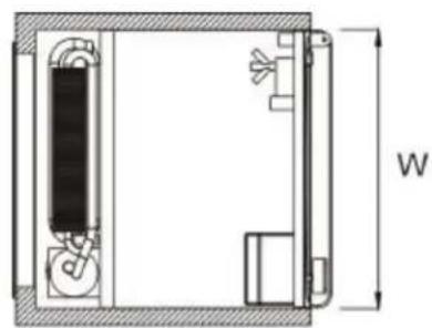
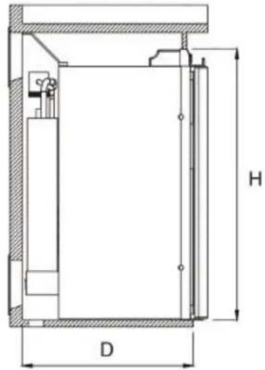
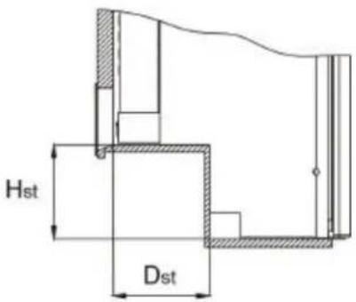
| Model | H | W | D | Hst | Dst |
| N80 | 825 | 490 | 515 | 220 | 235 |
| N100 | 825 | 529 | 515 | - | - |
| N145 | 1250 | 259 | 515 | - | - |
| N180 | 1250* | 529 | 540 | - | - |
- Incl. protruding latch: 1265 mm
CONTENTS
- INTRODUCTION 12
- SAFETY INSTRUCTIONS 12
- DETERMINING WHERE TO INSTALL THE REFRIGERATOR 13
- OUTSIDE VENTS 14
- COMBUSTION GASES OUTLET 15
- REFRIGERATION INSTALLATION 15
- ELECTRICAL COMPONENTS 16
- GAS CONNECTION INSTALLATION 18
- WIRING DIAGRAMS 18
1. INTRODUCTION
This installation manual concerns the Thetford absorption refrigerators for the After Market. This manual serves as a guide for the correct and safe installation of the refrigerator. Thetford refrigerators are a category C11 (EN 1749) product: "appliances with gas as energy source and which need to be installed isolated from the living area".
Read this installation manual carefully before installing the refrigerator. Referrals to explanatory illustrations at the beginning of this manual are common.
1.1 Application
This appliance has been designed for use in car avans and motor homes. When installing in any other vehicle, comply with the requirements set for that particular vehicle.
1.2 Technical data
Category C11*
AC 230V(50/60 Hz)
DC 12V
Gas type I3+ (G30: 28-30/G31: 37 mbar) (Countries: BE, FR, IE, LU, PT, ES, GB, GR, IT) I3B/P (G30/G31: 28-30 mbar) (Countries: DK, DE, IS, NL, SE, FI, NO) (G30 = Butane, G31 = Propane)
-
EN 732 specifications for liquid gas appliances – Absorption refrigerators
-
FIGURE 1: Specifications of other refrigerator models
| A | B | C | D | E | F | G | H | I | J |
| Model | Measurements H x B x D (mm) depth incl. door | Gross volume incl. freezer (L) | Net volume incl. freezer (L) | Volume freezer (L) | Input ** (kWh/24h) | Input ** (gr./24h) | Net weight (kg) | Operation | Ignition |
** average energy use at a surrounding temperature of 25°C and with proper installation
2. SAFETY INSTRUCTIONS
2.1 Alerts
The following alerts are used in this manual:


"Warning" indicates harm to the product or installer if the installer fails to carry out the described procedures carefully. Non-observance may result in serious injury to the installer or damage to the product.
"Guideline", points at a condition that needs to be taken into account during installation.
"Important" denotes supplementary information for the installer and alerts the installer to potential problems.
"Recommended", this situation is partially recommended.
"Discouraged", this situation is partially discouraged.
"Prohibited", this situation is not to occur.
2.2Warnings

- Install the refrigerator in accordance with the manufacturer's instructions and local/national laws.
Incorrect installation or maintenance of the refrigerator may cause physical injury and/or damage to the refrigerator. - Never use naked flames whilst performing maintenance or repairs on gas lines or when checking fittings for leaks. Gas may ignite and cause an explosion resulting in serious physical injury and/or damage to the product.
- Never reposition or change the electronic or gas components or parts.
- Never open or damage the cooling device at the rear of the refrigerator. The cooling system is pressurized and contains substances harmful to health.
- There are sharp edges and corners at the rear of the refrigerator. Always wear protection against cuts when installing the refrigerator.
- Install the refrigerator somewhere completely isolated (insulated) from the living area of the caravan or motor home. Air for the burner must not be drawn from the living area of the caravan or motor home and combustion gases must not enter the living area. Combustion gases may contain carbon monoxide. Inhalation of this gas may cause tightness of the chest, dizziness and can lead to death.
- Never expose the refrigerator to water or moisture.
- To cool the system and to supply the burner with a sufficient airflow, make sure that there is always sufficient ventilation through the outside vents.
- A qualified installation engineer must install the refrigerator.

- The refrigerator and its extractor must be installed in a way that allows easy access for maintenance and repairs.
- The installation and connections must satisfy the most recent technical regulations.
- The refrigerator is designed for powering by liquid gas (butane and propane), 12V DC or 230VAC.
- The performance of the refrigerator may be affected by adjacent heat sources such as an oven or stove. Protect the refrigerator against any heat source by fitting insulation.
3. DETERMINING WHERE TO INSTALL THE REFRIGERATOR
Various possibilities exist for positioning the refrigerator in a caravan or motor home. However, the refrigerator's performance depends on good ventilation. Ventilation takes place through two gratings in the wall of the caravan or motor home. When deciding where to position the refrigerator, you must take into account the best place for positioning the ventilation gratings.

Always make sure that the ventilation gratings can never be blocked. Blocked gratings reduce the supply and extraction of air. An insufficient air supply can result in incomplete combustion and the forming of carbon monoxide. Insufficient air extraction can also reduce the refrigerator's cooling performance.
2
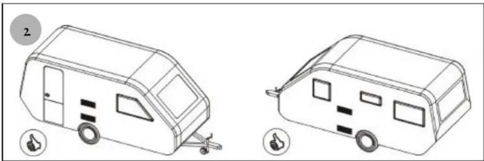
FIGURE 2: The perfect installation situations occur when the outside vents cannot be covered by e.g. doors.
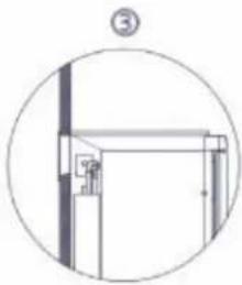
3.
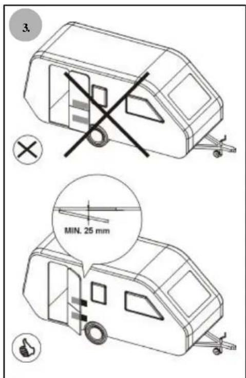
FIGURE 3: When the refrigerator is installed next to the caravan or motor home entry, it is imperative that the door, when open, does not block the ventilation gratings. Allow at least a 25mm distance between the ventilation gratings and the door.
4
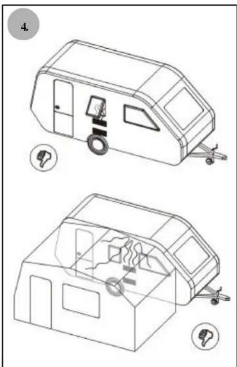
FIGURE 4: In this situation, combustion gases may enter the living area. Such installation situations are thus not recommended.
4 VENTILATION
Perfect ventilation is very important to ensure the cooling system works properly. Heat is generated in the cooling system. The heat must be able to escape into the open air. Cold air extraction is necessary to allow the cooling system to cool down again and to maintain the circulation of air.
5.
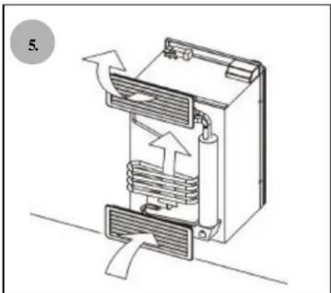
FIGURE 5: The refrigerator is ventilated by means of two openings in the wall of the caravan or motor home across which ventilation gratings are placed. Cold air comes in through the lower grating. The cooling system heats the cold air and it takes out again through the upper grating (chimney effect).
4.1 Installation ventilation gratings

- Install the ventilation gratings exactly as described in this manual.
Any other method of installation will invalidate the manufacturer's warranty for the refrigerator.
- Always fit the ventilation gratings at the rear of the refrigerator.
Fitting them at the side will reduce the refrigerator's cooling capacity.
6.
FIGURE 6: The lower ventilation grating

The lower ventilation grating should preferably be positioned behind the burner
box and the power board. This grating is also used for access during periodical Maintenance and repairs to the refrigerator.

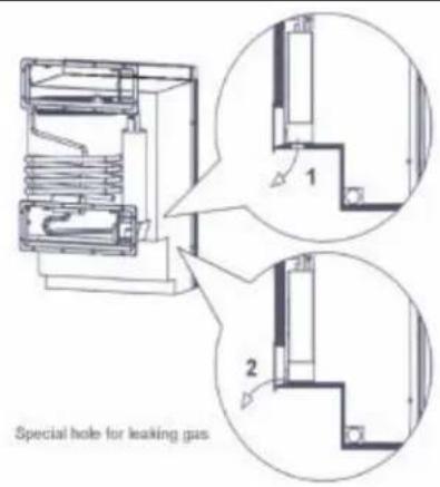
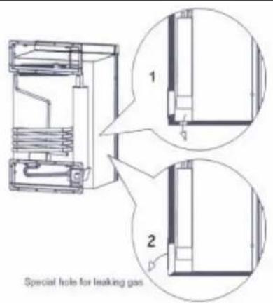
At the bottom of the combustion area there must be a hole in the floor. If a gasleak occurs this hole will allow gas (which is heavier than air) to stream outside instead of building up on the floor. For this purpose there should be a hole in the floor which leads directly outside, with a diameter in conformity with local regulations, but we advice a diameter of at least 0.40mm .

If it is not possible to make a hole in the bottom, it is possible to make a proper installation by positioning the bottom of the lower ventilation grating lower than the burner box. In this way the gas has the possibility to escape through the grating before reaching the burner flame.
However might mean that the refrigerator will have to be removed from the vehicle in case of maintenance or repair of the burner box or powerboard.
7.
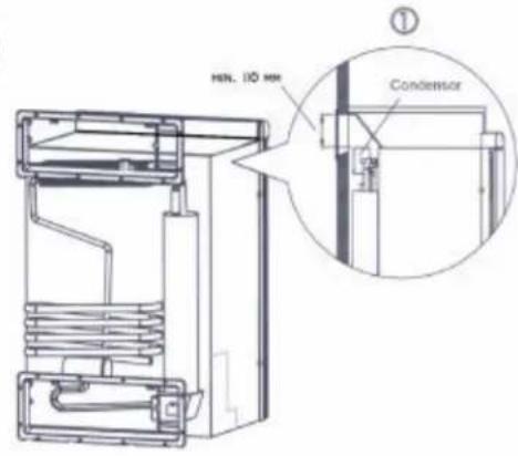
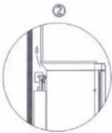
FIGURE 7: The upper ventilation grating
The installation of the upper ventilation grating influences the cooling capacity. The best result is achieved when this grating is installed as far above the condenser as possible. For Thetford small vents use at least 110mm distance between the top of the refrigeration cabinet and the top of the ventilation cut-out. Situation [1] is the preferred installation procedure for small vents and creates there the optimal cooling capacity. Situation [3] is the preferred installation procedure for large vents and creates there the optimal cooling capacity. Situation [2] is without a ventilation grating at the topside of the fridge, but with a chimney on the roof, which is also a possibility.
4.2 Installation ventilation gratings
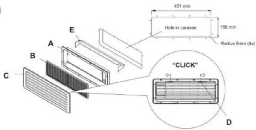
8.
FIGURE 8: A ventilation system compromises of two sets of a vent frame [A], a vent screen [B], and a vent outer [C]. The large vents do not have a vent screen [B]. To install the ventilation gratings, make, using the templates provided, a horizontal rectangular recess in the wall of the caravan or motor home..
- Use the accompanying template to cut out the ventilation recess.
- Seal the vent frame [A] in a watertight way by means of sealant or butyl tape.
- Only for the upper ventilation grating a small vents: assembly the vent cap [E] together with the vent frame.
- Position the vent frame [A] in place.
- Place the vent screen [B] in the vent frame (only for small vents).
- Place the vent outer [C] over the vent frame[A] and fasten it with the two retaining slides.
- The air for the burner must not come from the living area of the caravan or motor home and combustion gases must not enter the living area. The refrigerator must therefore be installed in a place completely separated (insulated) from the living area of the caravan or motor home.
- The fully installed refrigerator must allow the proper and complete discharge of combustion gases. Combustion gases may contain carbon monoxide. Inhalation of this gas may cause tightness of the chest, dizziness and can lead to death.
- The refrigerator is designed for powering by liquid propane gas, butane gas or a mixture.

- A qualified person must install gas components.
- The gas components must be installed in accordance with the latest technical regulations.
- Combustion gases must always be discharged upwards.
- The exhaust of the refrigerator must be installed so that it is always accessible for maintenance and repairs.
5.1 Installing the flue exhaust system
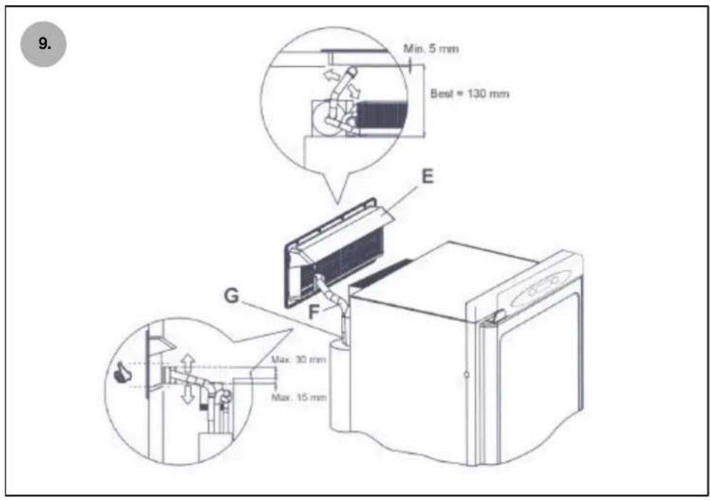
9.
FIGURE 9: The flue cap [E] has to be assembled together with the vent frame [A]. The exhaust tube [F] takes care of transporting the exhaust fumes and created heat outside the combust ion area. The outlet of the exhaust tube has to be close to the bottom-side of the vent. By rotating (see arrows) the exhaust tube and sliding it over the flue [G] you can adjust it so that the outlet of the exhaust is in the position as shown in the drawing below.

- It is important to always keep a distance of 5mm minimum from the vent!
- The outlet of the exhaust tube has to be close to the bottom-side of the vent.
- When positioned correctly, use the clamp to fix the exhaust tube to the flue of the refrigerator.
For refrigerator model N145 and N180 only
You do not need to install a separate extractor. The combustion gases will automatically be extracted properly via the upper ventilation grating after installation of the refrigerator.
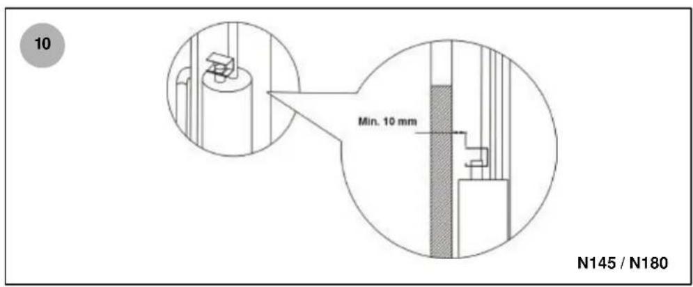
10.
FIGURE 10: Check that the minimum distance between the cover and the sides of the caravan or motor home is at least 1cm . Make sure that the closed side of the cover faces the refrigerator.
6. INSTALLING THE REFRIGERATOR

- The air from the burner must not come from the living area of the caravan or motor home and combustion gases must not enter the living area. The refrigerator must be installed in a place completely separated (insulated) from the living area of the caravan or motor home.

- The performance of the refrigerator is affected by the way it is installed.
- The performance of the refrigerator may be affected by adjacent heat sources such as an oven or stove. Protect the refrigerator against any adjacent heat source by fitting insulation.
- Make sure the floor is solid and even. The floor must be able to take the weight of the refrigerator with its contents.
6.1 Fitting margins
11.
FIGURE 11 / 12: If you use Thetford combustion seals, the dimensions as mentioned in table 11/12 are required.
6.2 Securing the refrigerator
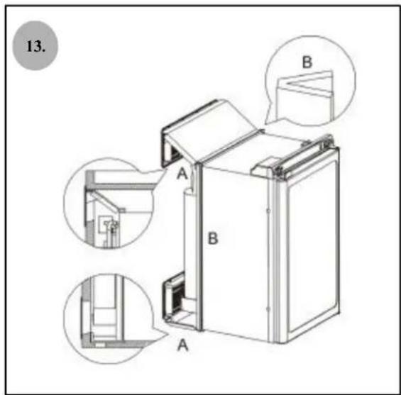
13.
FIGURE 13: If you use Thetford combustion seals, these need to be fixed in the way shown in the drawing to ensure optimum insulation. Fix the upper and lower flap of the combustion seal. Fix the strips to the sides of the refrigerator in a vertical direction at the rear of the refrigerator. Fix the upper and lower flap of the combustion seal in the way shown in the drawing.
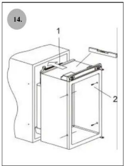
14.
FIGURE 14: The refrigerator is installed in the unit using four screw holes on the sides (the N145 models have got six screw holes).
- Place the refrigerator completely straight in the unit (when the caravan or motor home is level, the refrigerator should also be level).
- Put screws through the holes on the inside of the refrigerator and screw it through the wall of the refrigerator into the unit.
- Place the white caps over the holes.

If the size of the unit is such that the combustion seal fails to seal properly, use a different kind of sealing to keep hazardous combustion gases out of the living area of the caravan or motor home.
6.3 Technical drawings
Technical drawings are available for every type of refrigerator. These are precise A1 (scale 1:5) drawings stating all relevant measurements of the refrigerator and its surrounding. If wished for, Thetford is able to send you the technical drawing of your refrigerator model.
6.4 Fitting the door panel
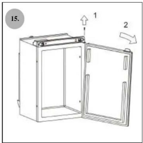
15.
FIGURE 15: In order to fit the door panel, the refrigerator's door needs to be demounted [1] Open the door, unfasten the screw from the top hinge point with a screwdriver and remove the screw. [2] Hold the door at a slight angle and lift the door from the lower hinge pen.
[3] Remove the 3 screws with which the lower cover is attached to the door.
[4] Remove the cover and slide the panel into the holder.
[5] Repeat steps [1] / [2] and [3] in reversed order.
7. ELECTRICAL COMPONENTS

- The electrical connections have to comply with EN 60335-1
- A qualified person must install the electrical connection.
- The electrical components must be in accordance with the latest technical regulations.
- Wiring must be installed so that wires cannot come into contact with hot or sharp parts.
7.1 Connecting to the mains (230 V)

- Connecting the 230v cable to a properly earthed power point will increase the safety aspect.
- Make sure the power point is in a position that is easy to reach.
- Position the 230v power lead in such a way that it cannot come into contact with hot or sharp parts.
- The mains connection must be fitted with a 3 A fuse.
- In case of a damaged power lead with one of the SES models (Smart Energy Selection, see figure 1), this must be replaced with a Thetford power lead.
7.2 Connecting to a DC power supply (12 V) for piezo and electric models (fig. 1)
These models have two 12V connection points to prevent the battery from being discharged by the refrigerator when the engine is not running.
The high-current power supply (red cable+, white cable-) provides current to the 12V heating element of the cooling system. This connection point may supply 12V only when the engine of the car or motor home is running.
E Models (Figure 1): the low-current power supply (purple cable +, black cable -) provides a continuous current of 12V for ignition of the burner and the light in the refrigerator. The 12V supply is obtained via the connection to the car or motor home battery or via the 230V AC → 12V DC transformer.

- Make sure the power point is in a position that is easy to reach.
- Minimize voltage drops by thoroughly fixing the wires.
- Position the 12Vpower lead so that it cannot come into contact with hot or sharp parts.
- In connection with voltage drops in high-power supply, the diameter of the lead depends on the lead length: Leads longer than 6m→ for optimum performance the lead diameter should be 6mm2 (with a minimum of 4mm2 ).
- The high-current power supply must be fitted with a 12 A fuse, the low current supply must be fitted with a 1 A fuse.
7.3 Connecting to a DC power supply in vehicles with a separate D+ / E+ (engine running) signal
The high current connection (HC, red wire +, white wire -) provides current to the DC heater of The cooling system. This connection should be connected to a continues DC supply. Connect the red and the white wire directly without any breakers (e.g(contact) to the vehicle starter battery. This connection is protected on the power board with a 20A fuse.
The low current connection (LC, purple wire +, black wire -) provides a continuous current of DC for the power board of the refrigerator. This DC supply is obtained via the connection to the auxiliary battery or via the 230V AC → DC transformer. This connection is protected on the power board with a 2A fuse.
The D+ connection (orange wire +) ensures the DC heater can not be switched on (manual or automatic) when the engine of the vehicle is not running.
Connect the D + connection to a DC connection point that shows that the vehicle's engine is running (engine running: DC, engine not running: no voltage)
This connection is only used as a signal cable.

- Position the connecting point so that it is easy to reach.
- Make sure that all connections are properly fastened to minimize voltage drops.
- Use wires with a diameter of 10mm2 (with a minimum of 6mm2 ) to ensure optimum performance of the refrigerator.
- Position the DC power lead in such a way that it cannot come into contact with hot or sharp parts.
- In connection with voltage drops in high power supply, the diameter of the leads depends on the lead length: Leads longer than 6m→ for optimum performance the lead diameter should be 6mm2 (with a minimum of 4mm2 ).
- In conformity with EN 1648-1/2 the respective negative and positive wires of the DC connections high current and low current can not be connected together.
8. CONNECTING THE GAS SYSTEM

- The gas connection has to comply with EN 1949 and EN 732
- Gas components may be installed only by a qualified installer. Be sure to use high-quality approved parts.
- The gas components must be installed in accordance with the latest technical regulations.
- Gas pipes or hoses must be fitted so that they cannot come into contact with hot or sharp parts.
- Keep flammable materials well away from the refrigerator.
- The refrigerator's gas supply must be fitted with a gas valve that allows the gas supply to be switched off. The gas valve must be readily accessible by the user.
- Make the connections airtight by means of an approved connector in accordance with local regulations.
- If you use a gas hose, make sure it is of an approved type in accordance with local regulations.
- Position the hose in such a way that it is not twisted, cannot turn and cannot buckle.
- A gas hose has a limited service life. Therefore, install the hose in a way that allows its easy replacement. Check the hole regularly for breaks, cracks, and ageing. Replace the hose if you are in any doubt. Take notice of the maximum life of the hose and replace it on time subject to the limits specified by the manufacturer or local regulations.
- Make a hole in the floor at the rear end of the refrigerator (Fig. 6). If a gas leak occurs, this hole will allow the gas to stream outside instead of building up on the floor. This hole must be in conformity with local regulations, but we advice a diameter of at least φ 40 mm. If it is not possible to make a hole in the bottom, it is also possible to position the lower ventilation grating at floor level or just below. In this way the gas has the possibility to escape through the grating. However this means that the refrigerator or will have to be removed from the vehicle in case of maintenance or repair of the burner box or powerboard. At places where metal gas lines enter the floor, affix a watertight and airtight rubber band around the pipe to prevent vibration and wear.
- Check the gas connection for leaks after the complete installation of the refrigerator.
16

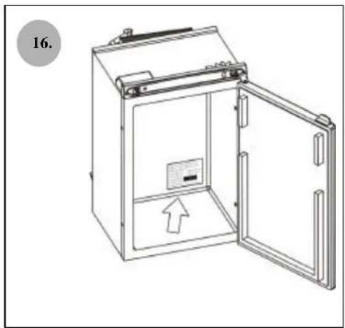
- FIGURE 16: Refer to the type plate on the inside of your refrigerator and to the table at the front of this booklet when choosing a gas type.
- Refer to the type plate on the inside of the refrigerator for the pressure setting of the gas pressure control.
1. WIRING DIAGRAMS
17
FIGURE 17: Wiring diagram N80 + N100
18
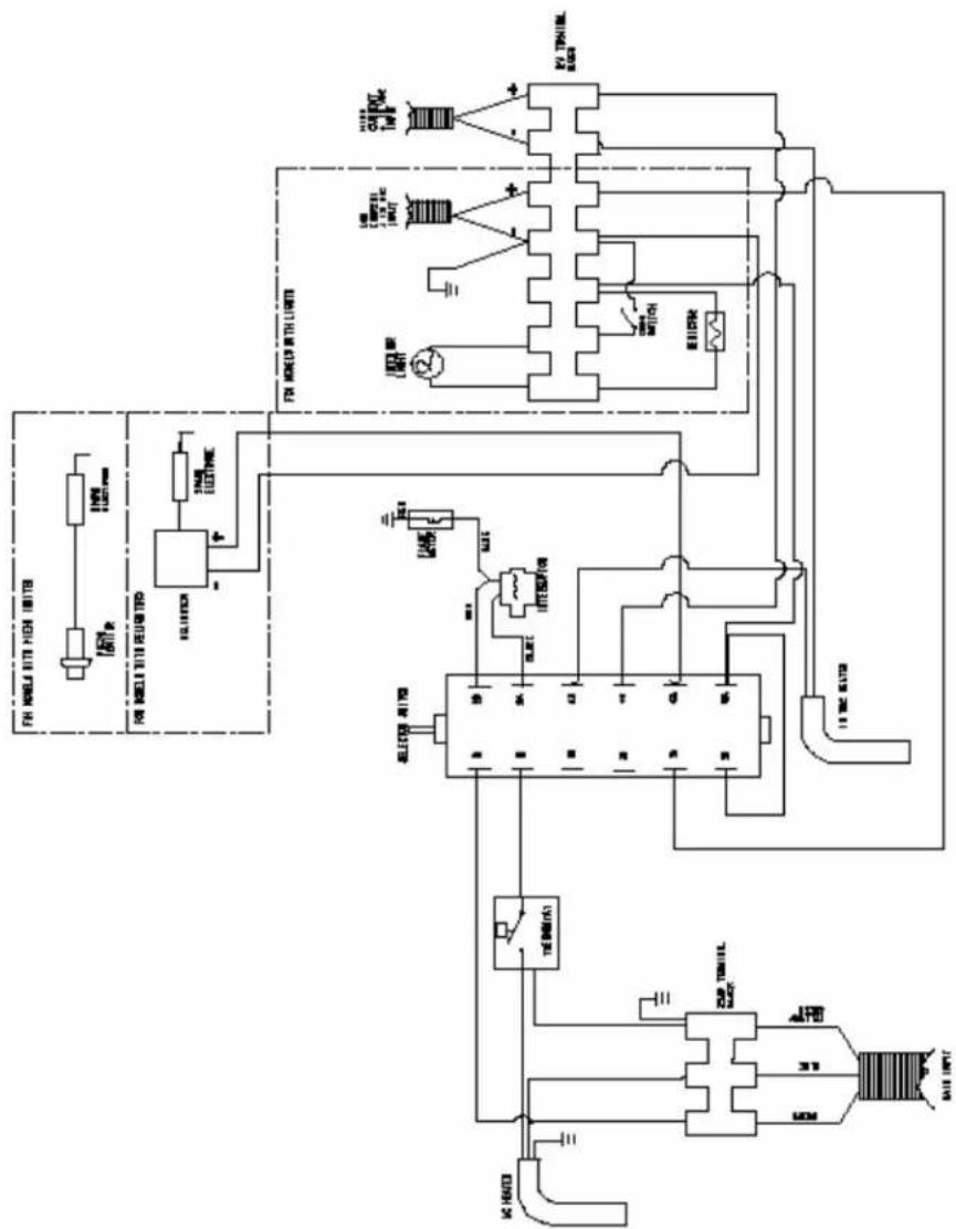
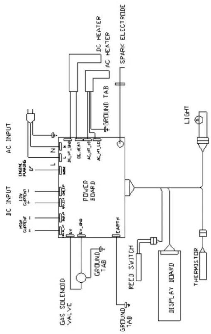
FIGURE 18: Wiring diagram N145
19
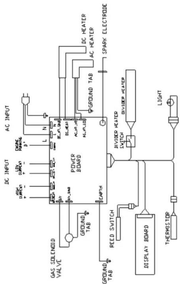
FIGURE 19: Wiring diagram N180.
SOMMAIRE
- INTRODUCTION 20
- CONSIGNES DE SECURITE 20
- CHOIX DE L'EMPLACEMENT D'INSTALLATION DU REFRIGERATEUR 21
- SYSTEME D'AERATION 22
- EXTRACTION DES GAZ DE COMBUSTION 23
- INSTALLATION DU REFRIGERATEUR 23
7.COMPOSANTS ELECTRIQUES 24 - BRANCHEMENT DE L'INSTALLATION DE GAZ 26
- SCHEMAS DE CABLAGE 26
1. INTRODUCTION
I3B/P (G30/G31: 28-30 mbar)* (Pays: DK, DE, IS, NL, SE, FI, NO)
(G30 = Butane, G31 = Propane)
6.3 Croquis techniques
I3B/P (G30/G31: 28-30 mbar)* (Nazioni: DK, DE, IS, NL, SE, FI, NO)
(G30 = Butano, G31 = Propano)

- FIGURES FOR INSTALLATION 2
- CONTENTS
- INTRODUCTION
- 1.1 APPLICATION
- 1.2 TECHNICAL DATA
- SAFETY INSTRUCTIONS
- 2.1 ALERTS
- 2.2WARNINGS
- DETERMINING WHERE TO INSTALL THE REFRIGERATOR
- 4 VENTILATION
- 5
- 4.1 INSTALLATION VENTILATION GRATINGS
- 6
- FIGURE 6: THE LOWER VENTILATION GRATING
- 7
- FIGURE 7: THE UPPER VENTILATION GRATING
- 4.2 INSTALLATION VENTILATION GRATINGS
- 8
- 5.1 INSTALLING THE FLUE EXHAUST SYSTEM
- INSTALLING THE REFRIGERATOR
- 6.1 FITTING MARGINS
- 6.2 SECURING THE REFRIGERATOR
- 13
- 14
- 6.3 TECHNICAL DRAWINGS
- 6.4 FITTING THE DOOR PANEL
- 15
- ELECTRICAL COMPONENTS
- 7.1 CONNECTING TO THE MAINS (230 V)
- 7.2 CONNECTING TO A DC POWER SUPPLY (12 V) FOR PIEZO AND ELECTRIC MODELS (FIG. 1)
- 7.3 CONNECTING TO A DC POWER SUPPLY IN VEHICLES WITH A SEPARATE D+ / E+ (ENGINE RUNNING) SIGNAL
- CONNECTING THE GAS SYSTEM
- WIRING DIAGRAMS
- SOMMAIRE
- 6.3 CROQUIS TECHNIQUES
Brand : THETFORD
Model : N145 Automatic Premium LCD
Category : Refrigerator