ASW610 - Subwoofer BOWERS & WILKINS - Free user manual and instructions
Find the device manual for free ASW610 BOWERS & WILKINS in PDF.

| Product Type | Active subwoofer |
| Brand | Bowers & Wilkins |
| Model | ASW610 |
| Mains power supply | 230 V AC, external protection fuse |
| Power consumption | Standby < 0.5 W (estimate) |
| Operating indicator | Green (active), red (standby) |
| Power switch | On / Auto (auto standby after 5 min) / Standby (triggered by 12V) |
| 12V Trigger input | Yes, for remote activation |
| Line level inputs | 2 x RCA (left and right) |
| Speaker level inputs | 2-way binding posts (left and right) |
| Line volume control | Potentiometer (min to max) |
| Speaker volume control | Potentiometer (min to max) |
| Crossover frequency adjustment | Low-pass filter, adjustable from 40 Hz to 140 Hz |
| Low-pass filter selector | IN (enabled) / OUT (disabled, for processor use) |
| Bass extension selector | A (max), B (medium), C (min) |
| Equalization switch | A (drier response, suitable for corners), B (for less resonant rooms) |
| Phase switch | 0° / 180° |
| Front grille | Removable |
| Supplied accessories | 4 M6 spike feet, 4 M6 rubber feet, 4 locking nuts, 1 mains cable |
| Maintenance | Dust with a soft cloth; do not use abrasive products or liquids on the cabinet or drivers |
| Safety | Do not place objects or liquids on the device; unplug if not used for extended periods |
Frequently Asked Questions - ASW610 BOWERS & WILKINS
User questions about ASW610 BOWERS & WILKINS
0 question about this device. Answer the ones you know or ask your own.
Ask a new question about this device
Download the instructions for your Subwoofer in PDF format for free! Find your manual ASW610 - BOWERS & WILKINS and take your electronic device back in hand. On this page are published all the documents necessary for the use of your device. ASW610 by BOWERS & WILKINS.
USER MANUAL ASW610 BOWERS & WILKINS
ASW608 ASW610 ASW610XP
Figure 1 (ASW608/ASW610)
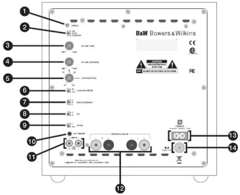
Figure 1 (ASW610XP)
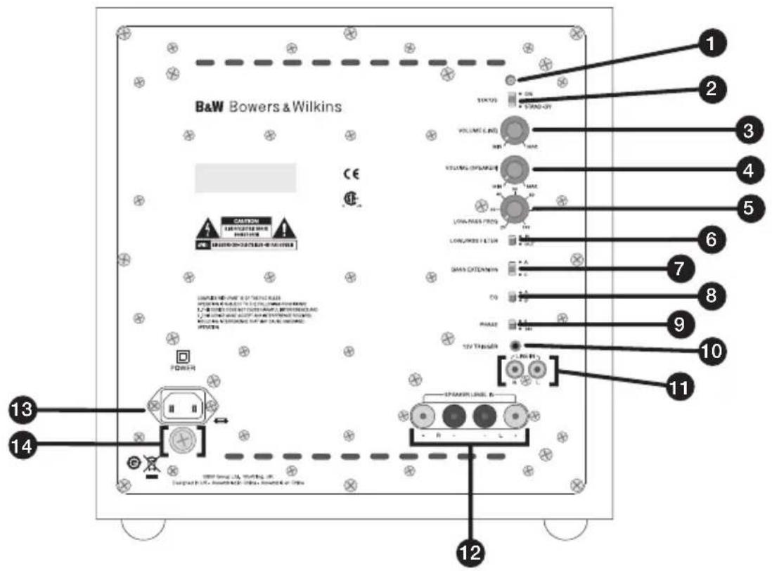
Figure 2 (ASW608/ASW610)
flowchart
graph TD
    A["Subwoofer"] --> B["Line Outputs"]
    B --> C["Subwoofer"]
    C --> D["RearCentre Front"]
    D --> E["Front Amplifier"]
    E --> F["Speaker Outputs"]
    F --> G["SPEAKERS"]
    H["Subwoofer"] --> I["Speaker Outputs"]
    I --> J["SPEAKERS"]
    K["Centre Channel Amplifier"] --> L["Input"]
    L --> M["L"]
    M --> N["R"]
    N --> O["Speaker Outputs"]
    O --> P["R"]
    P --> Q["L"]
    Q --> R["SPEAKERS"]
    S["Speaker Outputs"] --> T["R"]
    T --> U["L"]
    U --> V["SPEAKERS"]
Figure 2 (ASW610XP)
flowchart
graph TD
    A["Subwoofer"] --> B["Input L R"]
    B --> C["Centre Channel Amplifier"]
    C --> D["Line Outputs Subwoofer"]
    D --> E["RearCentre Front"]
    E --> F["Front Amplifier"]
    F --> G["Speaker Outputs R L"]
    G --> H["SPEAKERS"]
    C --> I["Speaker Outputs R L"]
    I --> J["SPEAKERS"]
    K["Speaker Outputs"] --> H
    L["Speaker Outputs"] --> H
    M["SPEAKERS"] --> H
Figure 3 (ASW608/ASW610)
flowchart
graph TD
    A["Processor"] --> B["Speaker Outputs"]
    B --> C["Subwoofer"]
    C --> D["Front"]
    D --> E["R"]
    D --> F["L"]
    D --> G["R"]
    D --> H["L"]
    B --> I["R"]
    B --> J["L"]
    B --> K["R"]
    B --> L["L"]
    B --> M["SPEAKERS"]
    N["Subwoofer"] --> O["Power Supply"]
    O --> P["Control Panel"]
    P --> Q["Power Supply / Control Panel"]
    Q --> R["Power Supply / Control Panel"]
Figure 3 (ASW610XP)
flowchart
graph TD
    A["Processor"] --> B["Speaker Outputs"]
    B --> C["Subwoofer"]
    C --> D["Front"]
    D --> E["R"]
    D --> F["L"]
    D --> G["R"]
    D --> H["L"]
    D --> I["R"]
    D --> J["L"]
    B --> K["SPEAKERS"]
    K --> L["Subwoofer"]
    L --> M["Speaker Outputs"]
    M --> N["Front"]
    N --> O["R"]
    N --> P["L"]
    N --> Q["R"]
    N --> R["L"]
Figure 4 (ASW608/ASW610)
flowchart
graph TD
    A["Processor"] --> B["Speaker Outputs"]
    B --> C["Front"]
    B --> D["Rear"]
    C --> E["Subwoofer"]
    D --> E
    E --> F["Speaker Status"]
    style A fill:#f9f,stroke:#333
    style B fill:#ccf,stroke:#333
    style C fill:#cfc,stroke:#333
    style D fill:#fcc,stroke:#333
    style E fill:#ffc,stroke:#333
    style F fill:#cfc,stroke:#333
Figure 4 (ASW610XP)
flowchart
graph TD
    A["Processor"] --> B["Speaker Outputs"]
    B --> C["Front"]
    B --> D["Rear"]
    C --> E["Subwoofer"]
    D --> E
    E --> F["Speaker"]
    style A fill:#f9f,stroke:#333
    style B fill:#ccf,stroke:#333
    style C fill:#cfc,stroke:#333
    style D fill:#fcc,stroke:#333
    style E fill:#ffc,stroke:#333
    style F fill:#cfc,stroke:#333
Figure 5 (ASW608/ASW610)
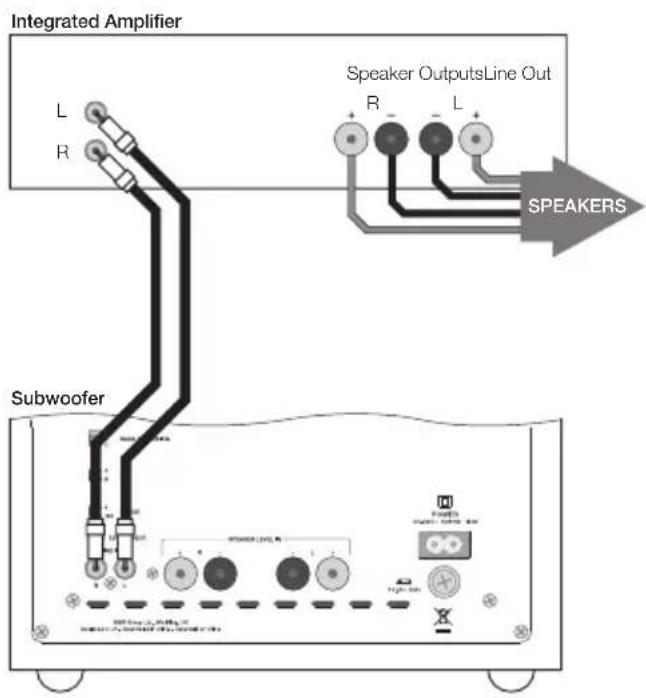
Figure 5 (ASW610XP)
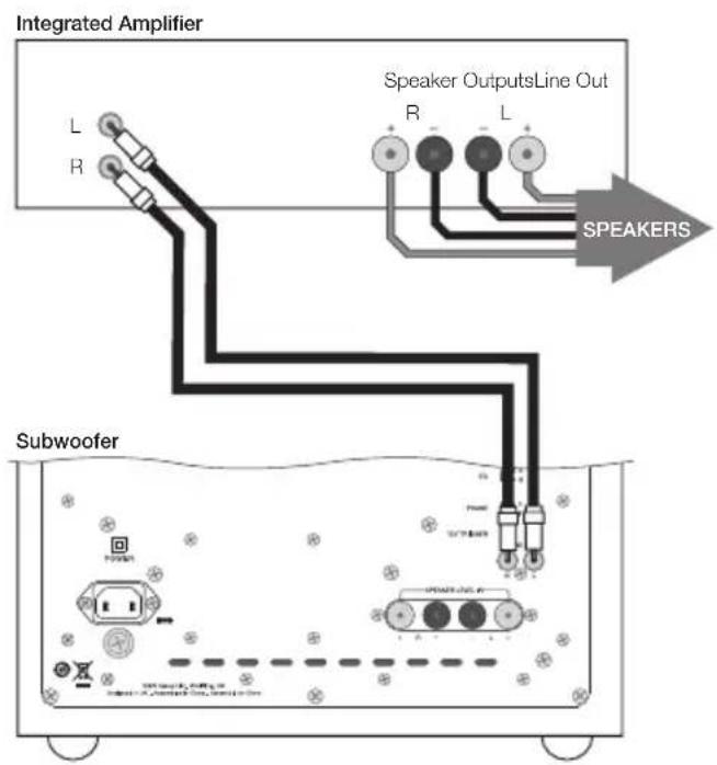
Figure 6 (ASW608/ASW610)
flowchart
graph TD
    A["Subwoofer"] --> B["Speaker Outputs"]
    B --> C["SPEAKERS"]
    C --> D["Integrated Amplifier"]
    style A fill:#f9f,stroke:#333
    style B fill:#ccf,stroke:#333
    style C fill:#cfc,stroke:#333
    style D fill:#fcc,stroke:#333
Figure 6 (ASW610XP)
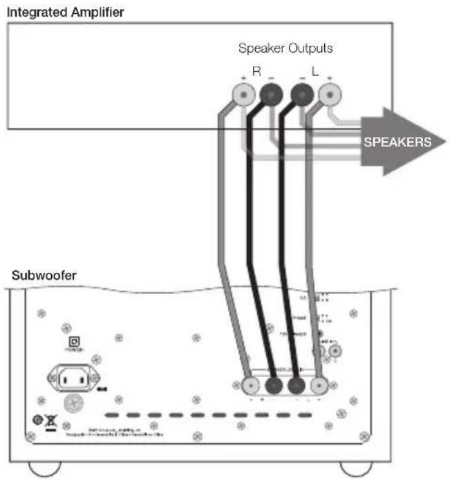
Figure 7 (ASW608/ASW610)
flowchart
graph TD
    A["Integrated Amplifier"] --> B["Speaker Outputs Line"]
    B --> C["Speaker R, L, R"]
    C --> D["Right Subwoofer"]
    D --> E["Left Subwoofer"]
    E --> F["Speaker R, L, R"]
    style A fill:#f9f,stroke:#333
    style B fill:#ccf,stroke:#333
    style C fill:#cfc,stroke:#333
    style D fill:#fcc,stroke:#333
    style E fill:#cff,stroke:#333
Figure 7 (ASW610XP)
flowchart
graph TD
    A["Integrated Amplifier"] --> B["Speaker Outputs Line"]
    B --> C["Level Outputs"]
    C --> D["SPEAKERS"]
    D --> E["Right Subwoofer"]
    E --> F["Left Subwoofer"]
    F --> G["Ground"]
    style A fill:#f9f,stroke:#333
    style B fill:#ccf,stroke:#333
    style C fill:#cfc,stroke:#333
    style D fill:#fcc,stroke:#333
    style E fill:#ffc,stroke:#333
    style F fill:#cfc,stroke:#333
    style G fill:#fcc,stroke:#333
Figure 8 (ASW608/ASW610)
Integrated Amplifier
flowchart
graph TD
    A["Right Subwoofer Left Subwoofer"] --> B["Output"]
    A --> C["Speaker"]
    B --> D["R"]
    B --> E["L"]
    C --> F["SPEAKERS"]
    D --> G["Speaker Output"]
    E --> G
    F --> G
    G --> H["Output"]
    style A fill:#f9f,stroke:#333
    style H fill:#ccf,stroke:#333
Figure 8 (ASW610XP)
Integrated Amplifier
flowchart
graph TD
    A["Right Subwoofer Left Subwoofer"] --> B["Output R"]
    A --> C["Output L"]
    B --> D["SPEAKERS"]
    C --> D
    D --> E["Output R"]
    D --> F["Output L"]
    style A fill:#f9f,stroke:#333
    style E fill:#ccf,stroke:#333
    style F fill:#ccf,stroke:#333
Figure 9 (ASW608/ASW610)
flowchart
graph TD
    A["Pre-Amplifier"] --> B["Line Out L R"]
    C["Power Amplifier"] --> D["Speaker Outputs Line In R L"]
    D --> E["SPEAKERS"]
    E --> F["Subwoofer"]
Figure 10 (ASW608/ASW610)
flowchart
graph TD
    A["Pre-Amplifier"] --> B["Line Out L R"]
    C["Power Amplifier"] --> D["Speaker Outputs Line In R L"]
    D --> E["SPEAKERS"]
    E --> F["Subwoofer"]
    F --> G["Power Switch"]
    F --> H["Ground"]
Figure 9 (ASW610XP)
flowchart
graph TD
    A["Pre-Amplifier"] --> B["Line Out L"]
    B --> C["R"]
    D["Power Amplifier"] --> E["Speaker Output Line In R"]
    E --> F["L"]
    G["Subwoofer"] --> H["Speaker Output Line In L"]
    H --> I["SPEAKERS"]
    style A fill:#f9f,stroke:#333
    style D fill:#f9f,stroke:#333
    style G fill:#f9f,stroke:#333
    style H fill:#ccf,stroke:#333
    style I fill:#cff,stroke:#333
Figure 10 (ASW610XP)
flowchart
graph TD
    A["Pre-Amplifier"] --> B["Line Out L R"]
    C["Power Amplifier"] --> D["Speaker Outputs Line In R - L +"]
    E["Subwoofer"] --> F["Speaker Outputs Line In R - L +"]
    G["SPEAKERS"] --> H["Speaker Outputs Line In R - L +"]
flowchart
graph TD
    A["Pre-Amplifier"] --> B["Line Out L R"]
    C["Power Amplifier"] --> D["Speaker Outputs Line In R L"]
    E["Left Subwoofer"] --> F["Subwoofer interface"]
    G["Right Subwoofer"] --> H["Subwoofer interface"]
    I["SPEAKERS"] --> D
    I --> H
flowchart
graph TD
    A["Pre-Amplifier"] --> B["Line Out L"]
    B --> C["R"]
    D["Power Amplifier"] --> E["Speaker Outputs Line In R"]
    E --> F["L"]
    G["Left Subwoofer"] --> H["Speaker Outputs Line In R"]
    I["Right Subwoofer"] --> J["Speaker Outputs Line In L"]
    K["SPEAKERS"] --> E
Figure 12 (ASW608/ASW610)

flowchart
graph TD
    A["Pre-Amplifier"] --> B["Line Out L R"]
    C["Power Amplifier"] --> D["Speaker Outputs Line In R L"]
    D --> E["SPEAKERS"]
    E --> F["Left Subwoofer"]
    E --> G["Right Subwoofer"]
    style A fill:#f9f,stroke:#333
    style C fill:#f9f,stroke:#333
    style E fill:#ccf,stroke:#333
    style F fill:#cfc,stroke:#333
    style G fill:#fcc,stroke:#333
Figure 12 (ASW610XP)
flowchart
graph TD
    A["Pre-Amplifier"] --> B["Line Out L R"]
    C["Power Amplifier"] --> D["Speaker Outputs Line In R L"]
    E["Left Subwoofer"] --> F["Speaker Output Line In R L"]
    G["Right Subwoofer"] --> H["Speaker Output Line In R L"]
    I["SPEAKERS"] --> J["Speaker Output Line In R L"]
    style A fill:#f9f,stroke:#333
    style C fill:#f9f,stroke:#333
    style E fill:#f9f,stroke:#333
    style G fill:#f9f,stroke:#333
    style I fill:#ccf,stroke:#333
Contents
English
Owner's Manual......11
Français
Specifications .....74–76
English
Owner's manual
Introduction
Dear customer,
Thank you for choosing Bowers & Wilkins. Please read this manual fully before unpacking and installing the product. It will help you to optimise its performance. B&W maintains a network of dedicated distributors in over 60 countries who will be able to help you should you have any problems your dealer cannot resolve.
Environmental Information


All B&W products are designed to comply with international directives on the Restriction of Hazardous Substances
(RoHS) in electrical and electronic equipment and the disposal of Waste Electrical and Electronic Equipment (WEEE). These symbols indicate compliance and that the products must be appropriately recycled or processed in accordance with these directives. Consult your local waste disposal authority for guidance.
Carton Contents
Check in the carton for:
1 Mains cable
1 Accessory pack containing:
4 M6 spike feet
4 M6 rubber feet
4 Lock nuts (10mm across flats)
Installation
The subwoofer has been designed both for Home Theatre installations and to augment the bass performance of 'full range' speakers in 2-channel audio systems. All audio installations require some thought in installation if they are to reach their full performance potential and this manual will guide you through the process.
The subwoofer requires connection to the mains power supply, so it is important that you familiarise yourself with the safety instructions and heed all the warnings. Keep this manual in a safe place for future reference.
The Subwoofer Connection and Control Panel (Figure 1)
- Status indicator.
- On, Auto, Stand-by switch.
- Line-level input volume.
- Speaker level input volume.
- Low-pass filter frequency.
- Low-pass filter selection switch.
- Bass extension switch.
- Equalisation switch.
- Phase reverse switch.
-
12V trigger input.
-
Line level input sockets (left and right).
- Speaker level input binding posts (left and right).
- Mains input.
- External fuse holder.
Subwoofer Applications
The primary function of a subwoofer is to reproduce signals from an audio-visual processor Low Frequency Effects (LFE) channel. In addition, the processor may be configured to divert the low bass portion from some or all of the other channels and add it to the LFE information. This is usually done by selecting “small” loudspeakers in the processor set-up procedure.
In 2-channel audio applications a subwoofer is used to extend the bass response lower than that provided by the satellite speakers. The subwoofer low-pass filter should be set so that the subwoofer takes over as the output of the satellite speakers falls.
Subwoofer Positioning and Installation
The ear poorly perceives the source location of low frequency sound so the position of subwoofers in the listening room is generally less critical compared to full-range speakers. However, best results are usually obtained if the subwoofer is placed between the left and right speakers or in the vicinity of one of them. If two subwoofers are used, it is best to put one near the left and one near the right speaker. Placing a subwoofer behind the listening position, even in multi-channel surround sound installations, generally results in inferior imaging, but may be an acceptable compromise if domestic considerations dictate.
As with all speakers, the proximity of room boundaries affects the sound of a subwoofer. Bass volume increases as more surfaces come into close proximity with the speaker. Unlike full-range speakers, however, the overall system balance can be corrected by adjusting the volume level of the subwoofer. The more boost gained from the room, the lower the volume can be set and the less hard the subwoofer has to work; but there is a down side. Subwoofers positioned near corners often generate more low-frequency room resonances, making the bass more uneven with frequency. There is no substitute for experiment as all rooms behave differently, so the subwoofer should be tried in a variety of positions before a final decision is made. A piece of music with a bass line ascending or descending the musical scale is useful for assessing the smoothness of the bass response. Listen for exaggerated or quiet notes.
If the subwoofer is to be used in a confined space (e.g. built into furniture), the space must be ventilated to allow sufficient air to circulate and cool the unit. Ask your dealer for advice.
The subwoofer is intended to be floor mounted only. It is important to ensure the subwoofer stands firmly on the floor using the spike feet supplied whenever possible. The spike feet are designed to pierce carpet and rest on the floor surface. Initially, screw the lock nuts onto the spikes enough to leave the nuts floating just above the carpet when the spikes are resting on
the floor beneath. Screw the spikes fully into the threaded inserts in the base of the cabinet. If the cabinet rocks when placed on the floor, unscrew the two spikes that do not touch the floor until the cabinet rests firmly without rocking. Finally, lock the nuts against the cabinet. It may be more convenient to fit and adjust the spike feet after speaker positioning has been optimised.
If there is no carpet and you wish to avoid scratching the floor surface, use either a protective metal disc (a coin perhaps) between the spike and the floor or use the supplied rubber feet. Fit the rubber feet by screwing one into each of the holes in the underside of the cabinet.
The grille fitted to the front of the subwoofer may be removed if desired. Take care however not to touch the moving parts of the drive unit as damage may result.
Using Multiple Subwoofers
Using multiple subwoofers in a single installation can improve performance in the following ways:
- Maintain stereo separation to the lowest frequencies.
- Smooth out the effects of low frequency room resonances.
- Enable a higher maximum sound output.
In the case of two subwoofers used in a 2-channel audio system, stereo separation will only be improved if each channel has its own subwoofer located close to the appropriate satellite speaker.
Electrical Connections
Disconnect all audio system equipment from the mains until the signal connections have been made and checked. This avoids the risk of damage whilst connections are made or broken. The subwoofer can accept both line level signals via the RCA Phono sockets (Item 11 in Figure 1) and speaker level signals via the binding posts (Item 12 in Figure 1). Use the following guide to select the appropriate connection method for your installation:
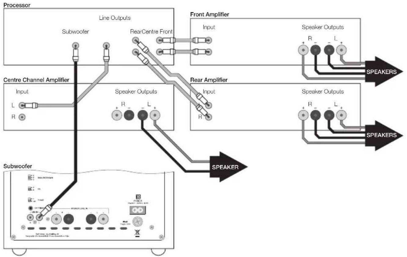
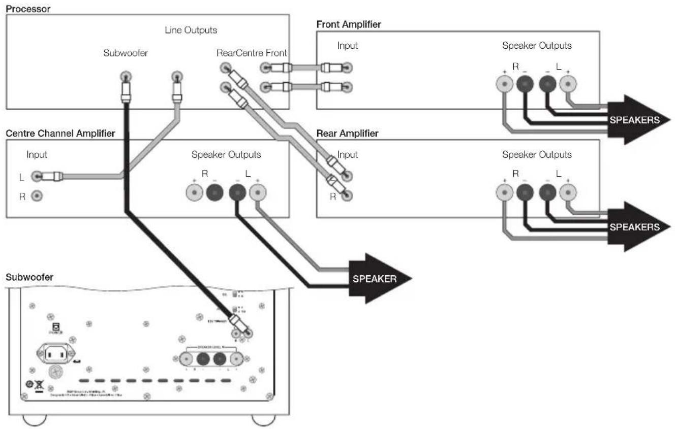
Application: Home Theatre
Subwoofer connected to AV Processor with separate power amplifiers: Figure 2
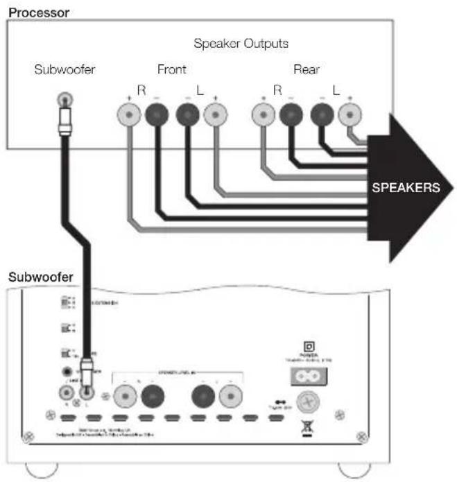
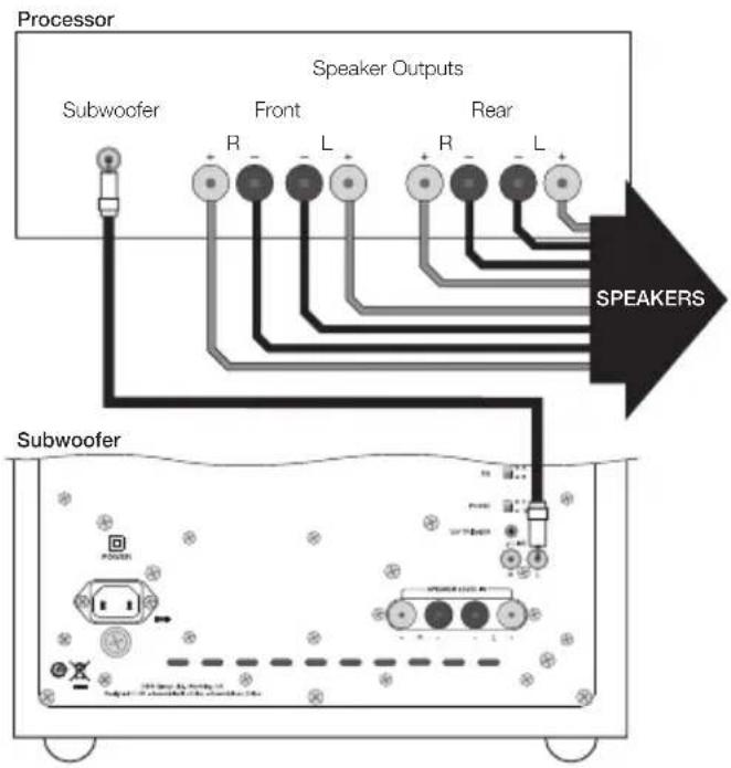
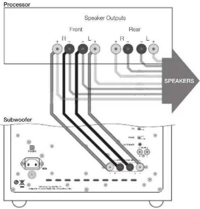
Subwoofer connected to AV Processor with integrated power amplifiers:
• using line-level inputs: Figure 3
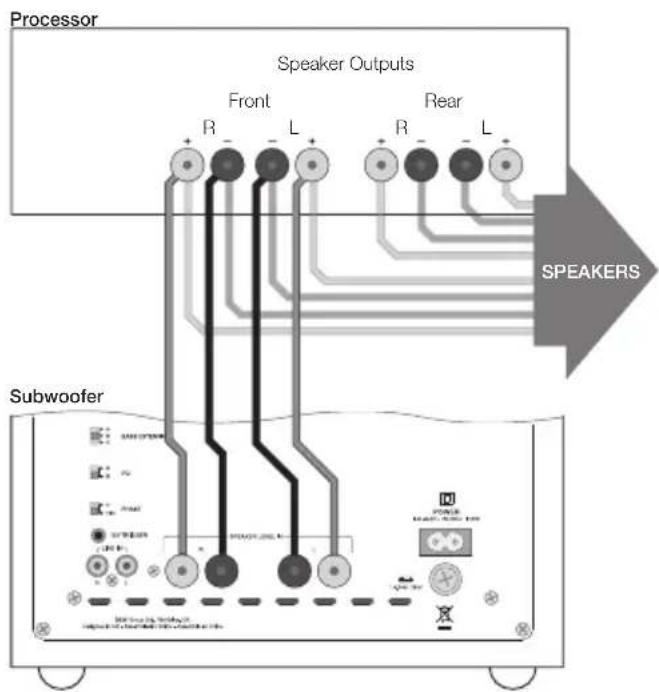
• using speaker level inputs: Figure 4
Note: The subwoofer is always better connected via its line level inputs in home theatre applications.
Application: 2-channel audio
Subwoofer connected to Integrated Amplifier:
• using line-level inputs: Figure 5
• using speaker level inputs: Figure 6
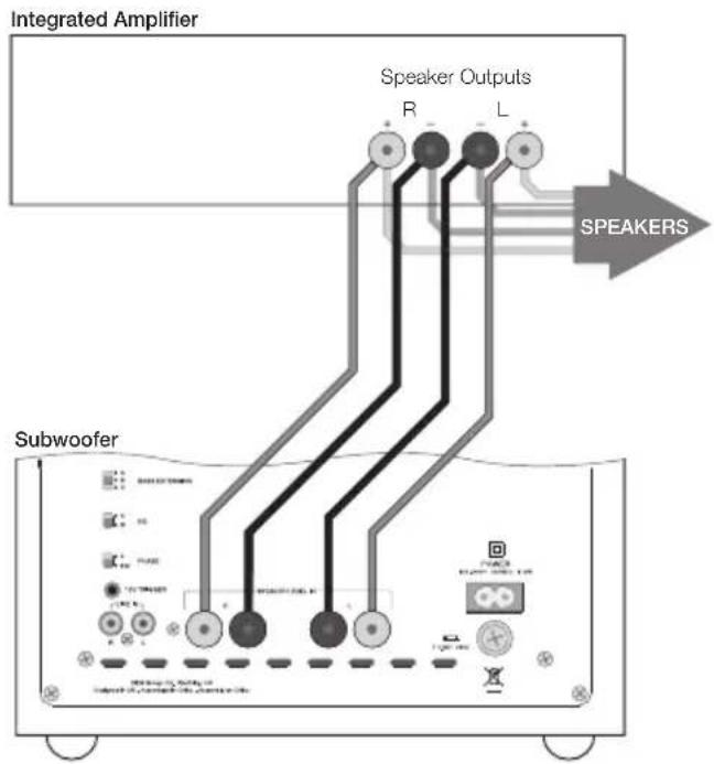
Two Subwoofers connected to Integrated Amplifier:
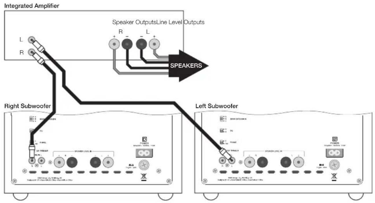
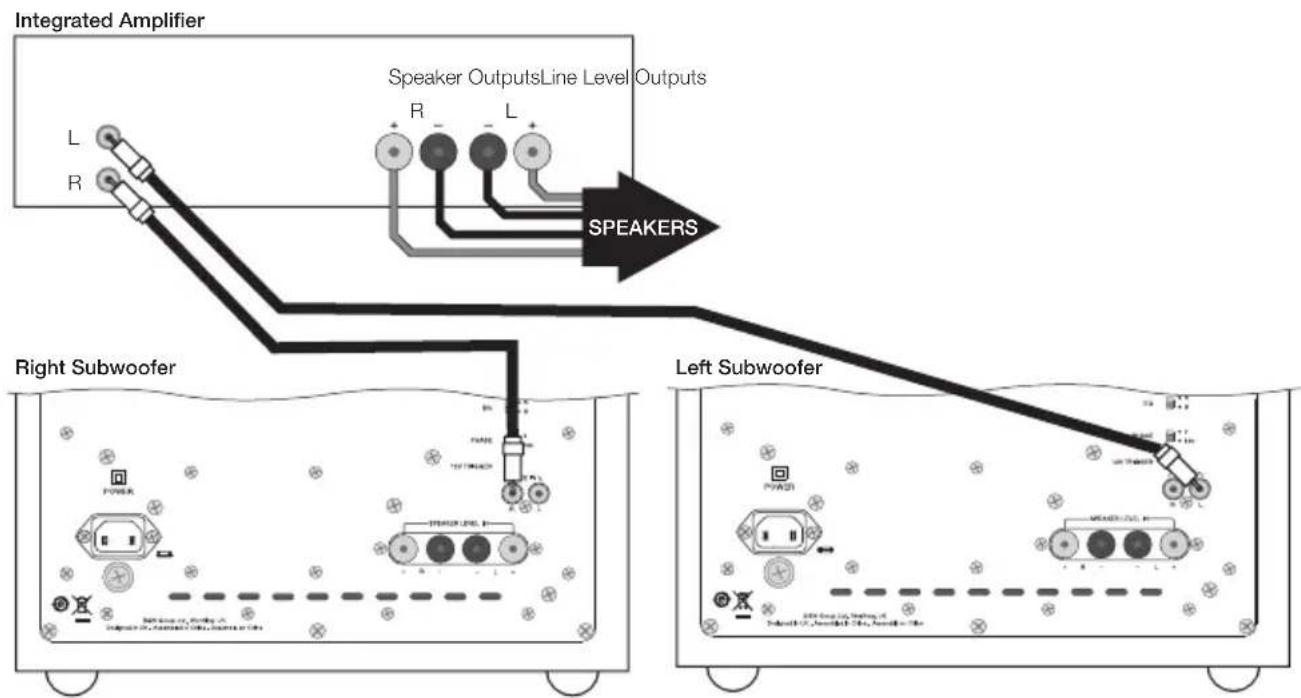
• using line-level inputs: Figure 7
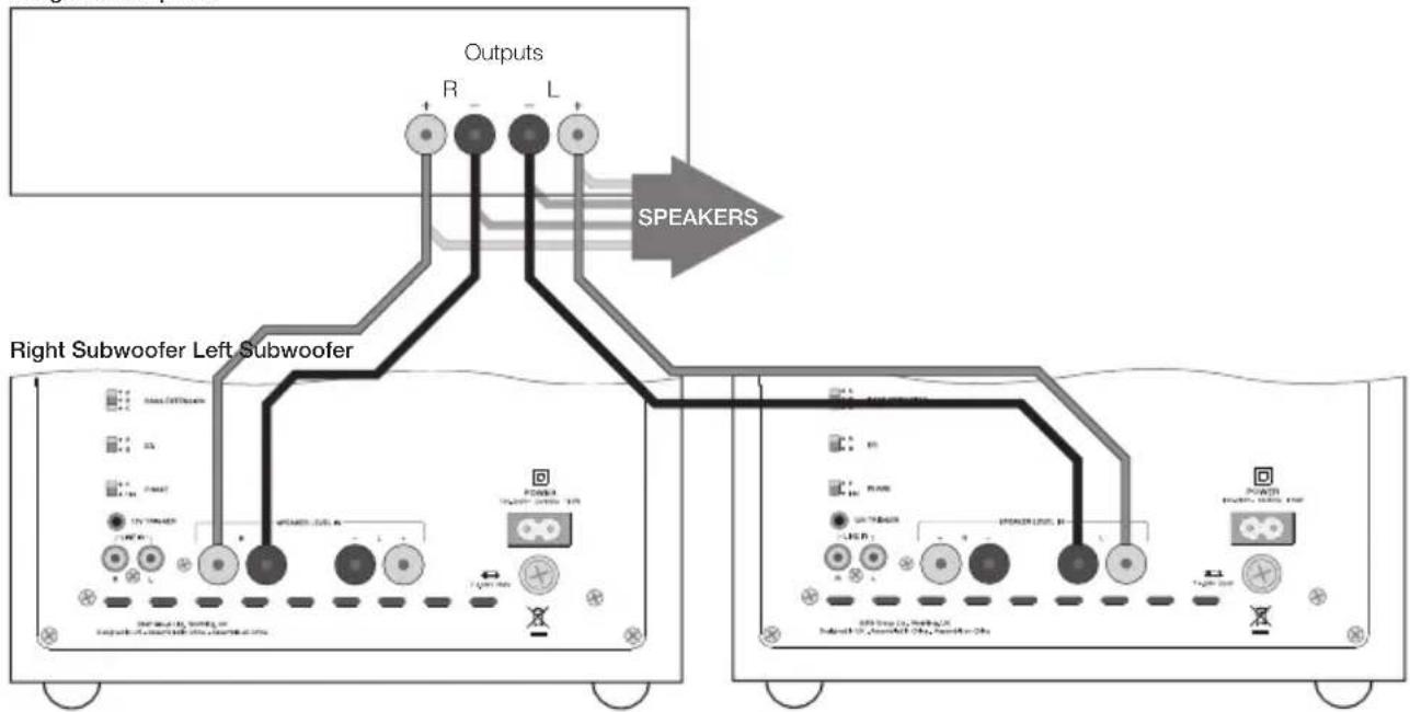
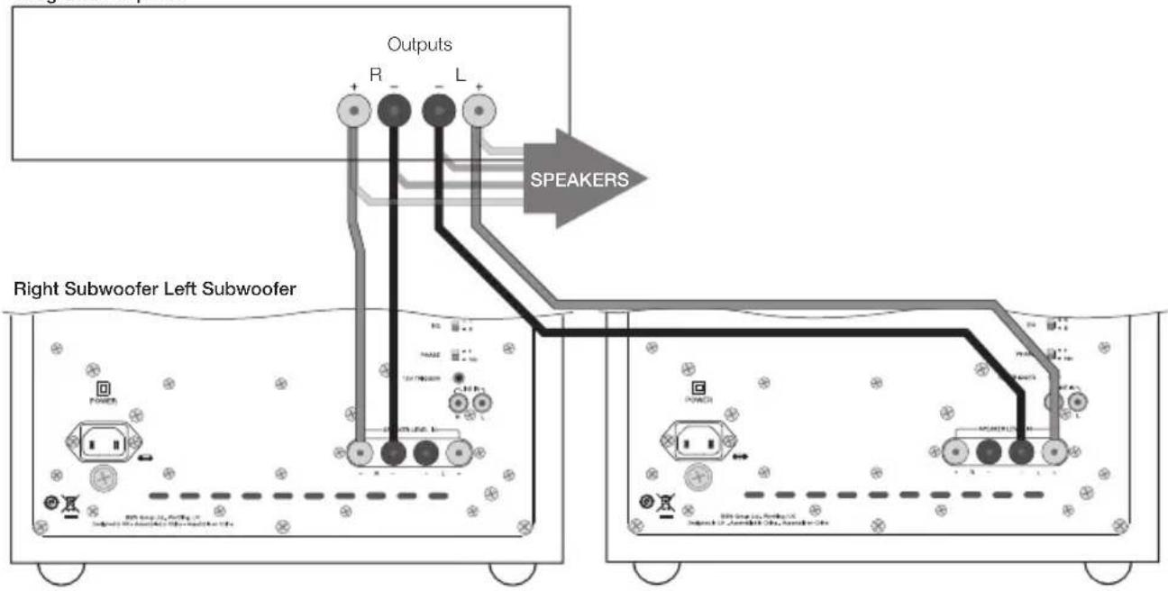
• using speaker level inputs: Figure 8
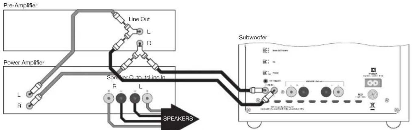
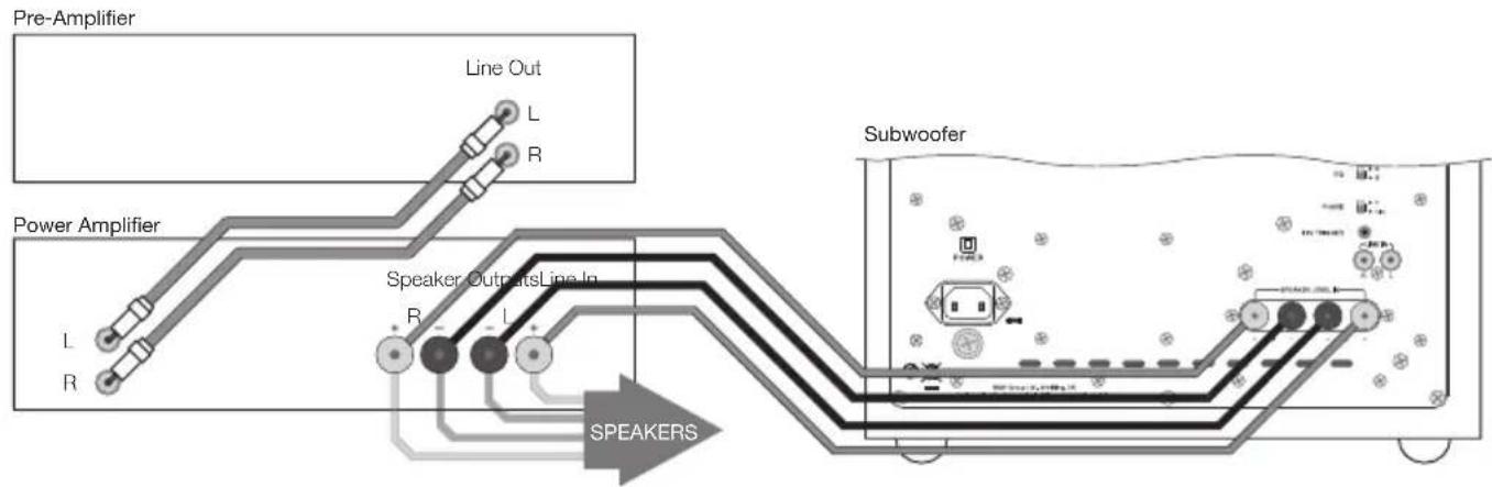
Subwoofer connected to Pre/Power Amplifier:
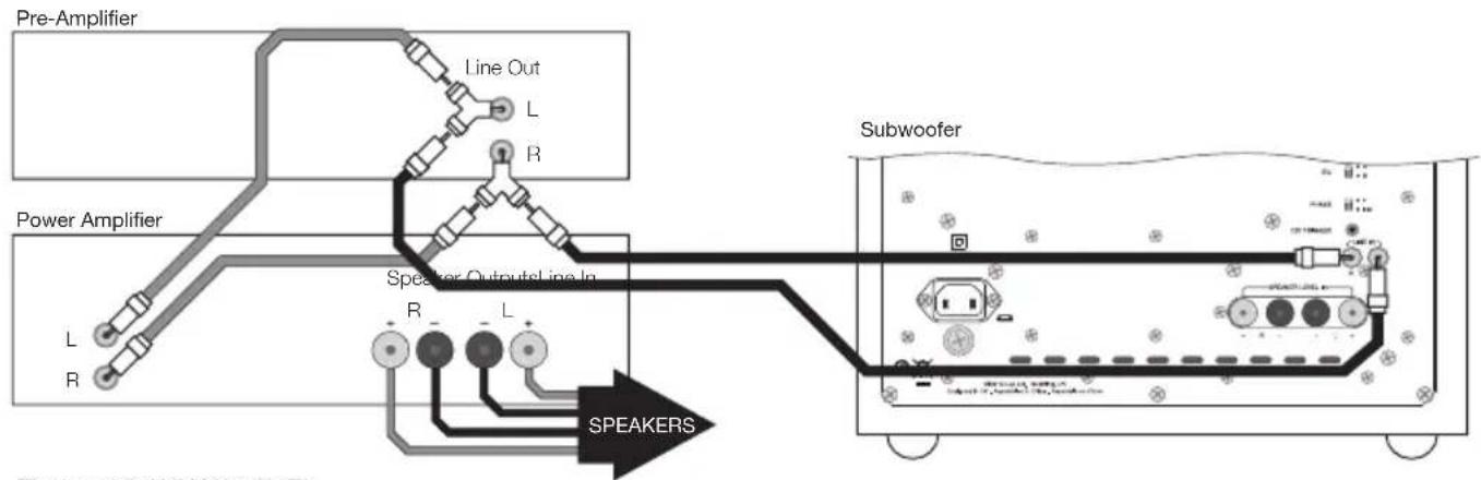
• using line-level input: Figure 9
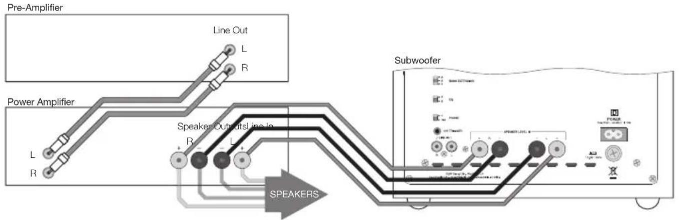
• using speaker level inputs: Figure 10
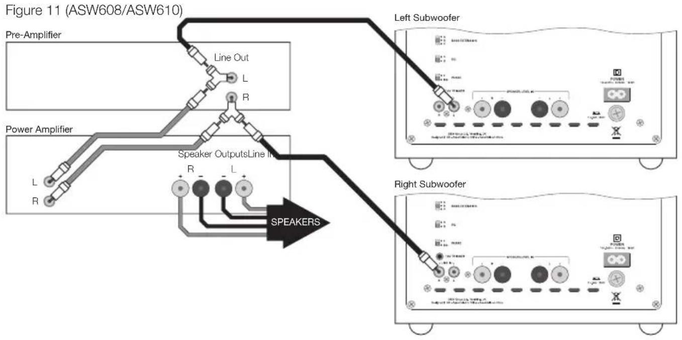
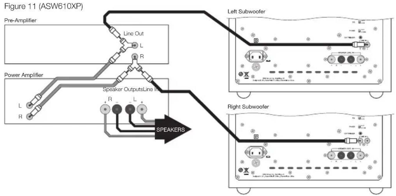
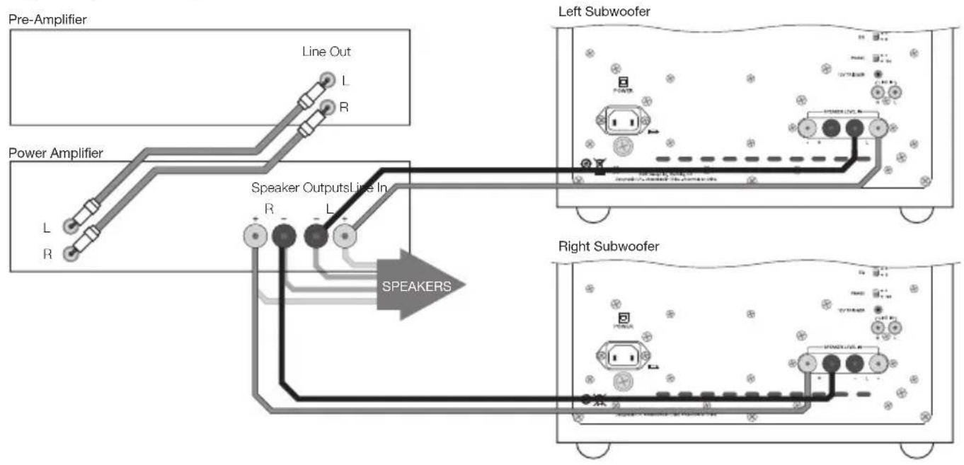
Two Subwoofers connected to Pre/Power Amplifier:
• using line-level inputs: Figure 11
• using speaker level inputs: Figure 12
Before Auditioning
Before auditioning your new subwoofer installation and fine-tuning it, double check the connections. Make sure in particular that:
- The phasing is correct. If the speaker level inputs are used, ensure that the positive terminals on the subwoofer (marked + and coloured red) are connected to the positive output terminals on the amplifier and that the negative terminals on the subwoofer (marked – and coloured black) are connected to the negative output terminals on the amplifier. Incorrect connection can result in a confused sound with poor bass.
- Left and right channels are not interchanged. Left/right confusion can result for example in orchestral elements appearing in the wrong place in the stereo image, or Home Theatre sound effects not matching the action on screen.
Switching On and Off
Subwoofers are best switched on after any other item and switched off first. The On/Auto/Standby switch (Item 2 in Figure 1) and Status Indicator (Item 1 in Figure 1) operate as follows:
On: With the switch to On, the subwoofer will remain fully active and the indicator will glow green.
Auto: With the switch set to Auto, the subwoofer will initially become fully active and the indicator will glow green. After about 5 minutes without an input signal, the subwoofer will automatically enter “sleep” mode. The indicator will glow red. When an input signal is detected, the subwoofer will automatically become active and the indicator will glow green. The subwoofer will return to sleep after about 5 minutes with no input signal.
Audio-visual processors incorporating an “automatic” set up procedure may be “confused” by subwoofers with an auto switch-on/sleep function. A potentially damaging fault condition can arise. Subwoofers are best left switched on and fully active during set up if such a processor is used.
Standby: With the switch set to Standby the subwoofer will become active when 12V is applied to the Trigger Input (Item 10 in Figure 1). Zero volts at the input will return the subwoofer to sleep. The indicator will glow green when the subwoofer is active and red when the subwoofer is in sleep.
Setting The Subwoofer Controls
There are 7 controls to consider:
• The VOLUME (LINE) control (Item 3 in Figure 1)
• The VOLUME (SPEAKER) control (Item 4 in Figure 1)
- The LOW-PASS FREQ (frequency) control (Item 5 in Figure 1)
- The LOW-PASS FILTER switch (Item 6 in Figure 1)
Note: This applies only to the LINE input. The filter is always in circuit with the SPEAKER LEVEL input.
• The BASS Extension switch (Item 7 in Figure 1)
• The EQ (equalisation) switch (Item 8 in Figure 1)
• The PHASE switch (Item 9 in Figure 1)
The appropriate settings depend on the equipment used with the subwoofer and the modes of connection. If using more than one subwoofer, ensure the controls on each one are set the same.
Note: The VOLUME (LINE) and VOLUME (SPEAKER) controls only operate on their respective line and volume inputs. An unused volume control is best set to Min.
Home Theatre Settings
Set the VOLUME (LINE or SPEAKER) control initially to the 9 o'clock position.
Set the LOW-PASS FILTER switch to OUT.
Set the EQ switch initially to position A.
Set the PHASE switch initially to 0^ .
Set the LOW-PASS FREQ (frequency) control to 140 if the speaker level inputs are used. The setting is irrelevant if the line level inputs are used.
See the "Fine Tuning" section for more.
The subwoofer is not a THX ^ licensed component, but may be used with a THX ^ controller if desired. If a THX ^ controller is used, ensure that the subwoofer function is enabled. This incorporates all the filtering and level setting required for the subwoofer in all modes. For level calibration, the internal test noise and channel level controls in the THX ^ controller should be used. In all cases the levels should be set to obtain 75dB SPL (C-weighted) at the listening position from the controller's internal noise test signal.
With other processors, configure the front and surround speakers to "large" or "small" as appropriate before setting the levels. Use the internal noise test signal and volume controls of the processor to set the levels of all the speakers. Only change the VOLUME control on the subwoofer if there is not enough range in the processor to achieve the correct levels. Inexpensive sound level meters are readily available from electronics stores and can be used to calibrate the levels. Refer to your processor manual for further details on how to set the levels.
2-channel Audio Settings
Set the VOLUME (LINE or SPEAKER) control initially to the 9 o'clock position.
Set the LOW-PASS FILTER switch to IN.
Set the EQ switch initially to position A.
Set the PHASE switch initially to 0^ .
Set the LOW-PASS FREQ control to match the -6dB low frequency cut-off frequency of the satellite speakers. Note: Both -3dB and -6dB figures can be found in the specification of each B&W speaker model. If the satellite speaker manufacturer quotes only a -3dB frequency, the optimum setting for the LOW-PASS FREQ control should be between 0.6 and 0.9 times that figure. The more gradual the low frequency roll-off of the satellite speakers, the lower the frequency should be set.
See the Fine Tuning section for more.
Fine-tuning
Home Theatre
In home theatre systems, the subwoofer (LFE) signal is a separate channel rather than an extension of the signal to the satellite speakers. The LOW-PASS FILTER is switched out (or set to maximum), because the processor provides all the filtering for any speakers set to "small". However, the position of the PHASE switch must still be assessed. Normally the phase will be set to 0°, but if the subwoofer is positioned at a distance significantly different from the other speakers, or the power amplifier driving the other speakers happens to invert the signal, the 180° position may be preferable. Listen with the switch in both positions and choose the one that gives the fullest sound. If there is little difference, leave the switch at 0°.
Surround sound processors normally have a calibrated noise signal that can be used to set the relative levels of all the speakers, making the task somewhat more straightforward than for 2 channel audio. However, do not be afraid to alter the settings to your personal preference. It is all too easy to get carried away with the capabilities of the subwoofer, especially with some special low-frequency effects. Often a more realistic portrayal, and one more satisfying in the long term, is to be had by setting the subwoofer level lower than the standard calibration level.
2-channel Audio
Set the system up in the preferred position and play some programme with a steady bass content.
The optimum settings of the PHASE switch and the LOW-PASS FREQ control are inter-related and also dependent on the low-frequency cut-off characteristic of the satellite speakers. However, the settings recommended above for the LOW PASS FREQ control and PHASE switch have been chosen to integrate well with most satellite speaker bass alignments.
Using the initial settings, first check the setting of the PHASE switch. Choose the option that gives the fullest sound. Normally the recommended option will be optimum, but may not be in certain circumstances. These may be that the power amplifiers feeding the satellite speakers invert the signal or that the subwoofer is not placed close to the satellite speakers.
Next, adjust the VOLUME (LINE or SPEAKER) of the subwoofer relative to the satellite systems to your liking. Use a wide variety of programme material to get an average setting. A setting that sounds impressive on one piece may sound overpowering on another. Listen at a realistic volume level as the perception of musical balance varies with sound level.
Finally, adjust the LOW-PASS FREQ control to give the smoothest transition between the subwoofer and satellite speakers.
All Applications
The BASS EXTENSION switch offers three options of subwoofer bass extension. Position A gives the greatest extension and position C gives the least extension. Position B provides a compromise setting. If the system is to be used at very high volume levels or in a large listening room, restricting the bass extension by selecting either B or C may help ensure that the subwoofer is not asked to exceed its performance limits. In most situations the BASS EXTENSION switch should be left in position A.
The EQ switch alters the subwoofer bass roll-off alignment. The bass you hear is a combination of the subwoofer plus the effects of the room and you should choose the position that best complements your room and the location of the subwoofer. Position A gives a "drier" alignment, more suited to placing the subwoofer in a corner or compensating for a resonant room. Position B is suited to a less resonant room acoustic and use away from a corner.
If you get problems with uneven bass – certain bass notes are exaggerated more than others – then you probably have a room interface problem and it is worth experimenting with the location of the subwoofer. What may seem like small changes in position – 15cm (6in) or so – can have a profound effect on the sound. The use of multiple subwoofers can smooth the effects of room resonances, as each subwoofer will tend to excite resonances at different frequencies. If you appreciably alter the relative distances from the subwoofer(s) and satellite speakers to the listening position, re-assess the PHASE switch setting. You should also check the volume of the subwoofer (using either the processor output levels or the VOLUME control on the subwoofer amplifier as appropriate), but only after setting the phase correctly.
Aftercare
The cabinet surfaces usually only require dusting. If you wish to use an aerosol or other cleaner, remove the grille first by gently pulling it away from the cabinet. Spray aerosols onto the cleaning cloth, not directly onto the product. Test a small area first, as some cleaning products may damage some of the surfaces. Avoid products that are abrasive, or contain acid, alkali or anti-bacterial agents. Do not use cleaning agents on the drive unit. The grille fabric may be cleaned with a normal clothes brush whilst the grille is detached from the cabinet. Avoid touching the drive unit, as damage may result. Switch off the subwoofer before cleaning.
Do not use the subwoofer as a table. When in use, objects left on top of the subwoofer are liable to rattle. In particular, avoid the risk of liquids being spilled (e.g. from drinks or vases of flowers).
If the system is taken out of use for a long period, disconnect the subwoofer from the mains supply.
Standards conformity
NORTH AMERICA

Conforms to ANSI/UL Standard 60065 7th Edition
certified to CAN/CSA Standard C22.2 No. 60065
Complies with Part 15 of the FCC Rules
Operation is subject to the following conditions:
- This device does not cause harmful interference and
- This device must accept any interference received, including interference that may cause undesired operation.
EU DECLARATION OF CONFORMITY
We,
B&W Group Ltd.
whose registered office is situated at
Dale Road, Worthing, West Sussex, BN11 2BH, United Kingdom
declare under our sole responsibility that the products:
ASW608, ASW610, ASW610XP
comply with the EU Electro-Magnetic Compatibility (EMC) Directive 89/336/EEC, in pursuance of which the following standards have been applied:
| EN 55020 : 2007 | Sound and television broadcast receivers and associated equipment - Immunity characteristics |
| EN 55013 : 2001 | Sound and television broadcast receivers and associated equipment - Radio disturbance characteristics |
| EN 61000-3-2 : 2000 | Electro-magnetic compatibility (EMC) — Part 3-2: Limits - Limits for harmonic current emissions (equipment input current up to and including 16A per phase) |
| EN 61000-3-3 : 1995 | Electro-magnetic compatibility (EMC) — Part 3-3: Limits - Limitation of voltage changes, voltage fluctuations and flicker in public low-voltage supply systems, for equipment with rated current ≤ 16A per phase and not subject to conditional connection |
and comply with the EU Low Voltage Directive 73/23/EEC and amendment 93/68/EEC, in pursuance of which the following standard has been applied:
EN 60065 : 2011 Audio, video and similar electronic apparatus - Safety requirements
This declaration attests that the manufacturing process quality control and product documentation accord with the need to assure continued compliance.
The attention of the user is drawn to any special measures regarding the use of this equipment that may be detailed in the owner's manual.
Signed:

G Edwards
Executive Vice President, Operations
B&W Group Ltd.
natural_image
Pure diagram of concentric circles inside a square frame with mounting holes (no text or symbols)ASW608
Description Active closed-box subwoofer system
Drive unit 1x ø200mm (8 in) paper/Kevlar® cone long-throw
Frequency range -6dB at 23Hz and 25/140Hz adjustable (EQ at A)
Frequency response ±3dB 32Hz - 40/140Hz adjustable (EQ at A)
Bass extension -6dB at 23Hz (position A)
-6dB at 28Hz (position B)
-6dB at 36Hz (position C)
Amplifier Power output: 200W
Rated power
consumption: 40W / 0.5W standby
Input impedance: 33k Ω
Signal / noise: >90dB
Functions: Volume level - line in
Volume level - speaker in
Low-pass filter frequency
Low-pass filter bypass
Bass extension
Bass roll-off alignment
Auto sense on/standby
Phase switch
Inputs: Line in (RCA Phono)
Speaker in (Binding post)
12v trigger (3.5mm jack)
Low-pass filter Active 4th-order, variable cut-off frequency
Dimensions Height: 260mm (10.2 in) not including feet
Width: 260mm (10.2 in)
Depth: 330mm (13 in) including grille and controls
Net weight 8.85kg (19.5 lb)
natural_image
Pure diagram of concentric circles inside a square frame with mounting holes (no text or symbols)ASW610
Description Active closed-box subwoofer system
Drive unit 1x ø250mm (10 in) paper/Kevlar® cone long-throw
Frequency range -6dB at 20Hz and 25/140Hz adjustable (EQ at A)
Frequency response ±3dB 27Hz - 40/140Hz adjustable (EQ at A)
Bass extension -6dB at 20Hz (position A)
-6dB at 25Hz (position B)
-6dB at 30Hz (position C)
Amplifier Power output: 200W
Rated power
consumption: 40W / 0.5W standby
Input impedance: 33k Ω
Signal / noise: >90dB
Functions: Volume level - line in
Volume level - speaker in
Low-pass filter frequency
Low-pass filter bypass
Bass extension
Bass roll-off alignment
Auto sense on/standby
Phase switch
Inputs: Line in (RCA Phono)
Speaker in (Binding post)
12v trigger (3.5mm jack)
Low-pass filter Active 4th-order, variable cut-off frequency
Dimensions Height: 310mm (12.2 in) not including feet
Width: 310mm (12.2 in)
Depth: 375mm (14.8 in) including grille and controls
Net weight 12.5kg (27.6 lb)
natural_image
Concentric circular rings inside a square frame, no text or symbols presentASW610XP
Description Active closed-box subwoofer system
Drive unit ø250mm (10 in) paper/Kevlar ^® cone long-throw
Frequency range -6dB at 18Hz and 25/140Hz adjustable (EQ at A)
Frequency response ±3dB 25Hz-40/140Hz adjustable (EQ at A)
Bass Extension -6dB at 18Hz (position A)
-6dB at 23Hz (position B)
-6dB at 28Hz (position C)
Amplifier Power output: 500W
Rated power
consumption: 94W
Standby: 0.8W
Idle (ON no signal) 11.8W
Input impedance: 33kΩ
Signal / noise: >80dB
Functions: Input level (line in)
Input level (speaker in)
Low-pass filter frequency
Low-pass filter bypass
Bass extension
Bass roll-off alignment
Auto sense on/standby
Phase switch
Inputs: Line In (RCA Phono)
Speaker in (Binding post)
12v trigger (3.5mm jack)
Low-pass filter Active 4th-order, variable cut-off frequency
Dimensions Height: 325 mm (12.2 in) not including feet
Width: 325 mm (12.2 in)
Depth: 374mm (14.7 in) including grille and controls
Net weight 15.5kg (34.4 lb)
Bowers & Wilkins
B&W Group Ltd
Dale Road
Worthing West Sussex
BN11 2BH England
T +44 (0) 1903221800
F +44 (0) 1903 221 801
info@bwgroup.com
www.bowers-wilkins.com
B&W Group (UK Sales)
T +44 (0) 1903221500
E uksales@bwgroup.com
B&W Group North America
T+19786642870
E marketing@bwgroupusa.com
B&W Group Asia Ltd
T+85234729300
E info@bwgroup.hk
Copyright © B&W Group Ltd. E&OE
Printed in China