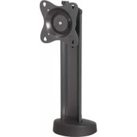
STS1 - Flat screen mount Chief - Free user manual and instructions
Find the device manual for free STS1 Chief in PDF.


User questions about STS1 Chief
0 question about this device. Answer the ones you know or ask your own.
Ask a new question about this device
Download the instructions for your Flat screen mount in PDF format for free! Find your manual STS1 - Chief and take your electronic device back in hand. On this page are published all the documents necessary for the use of your device. STS1 by Chief.
USER MANUAL STS1 Chief
INSTALLATION INSTRUCTIONS
natural_image
Technical line drawing of a mechanical device with mounting base and cylindrical body (no text or symbols)Small Swivel Table Stand
Petit support de table pivotant
DISCLAIMER
Milestone AV Technologies and its affiliated corporations and subsidiaries (collectively "Milestone"), intend to make this manual accurate and complete. However, Milestone makes no claim that the information contained herein covers all details, conditions or variations, nor does it provide for every possible contingency in connection with the installation or use of this product. The information contained in this document is subject to change without notice or obligation of any kind. Milestone makes no representation of warranty, expressed or implied, regarding the information contained herein. Milestone assumes no responsibility for accuracy, completeness or sufficiency of the information contained in this document.
Chief® is a registered trademark of Milestone AV Technologies. All rights reserved.

IMPORTANT SAFETY INSTRUCTIONS

WARNING: A WARNING alerts you to the possibility of serious injury or death if you do not follow the instructions.

CAUTION: A CAUTION alerts you to the possibility of damage or destruction of equipment if you do not follow the corresponding instructions.

WARNING: Failure to read, thoroughly understand, and follow all instructions can result in serious personal injury, damage to equipment, or voiding of factory warranty! It is the installer's responsibility to make sure all components are properly assembled and installed using the instructions provided.

WARNING: Failure to provide adequate structural strength for this component can result in serious personal injury or damage to equipment! It is the installer's responsibility to make sure the structure to which this component is attached can support five times the combined weight of all equipment. Reinforce the structure as required before installing the component.

WARNING: Exceeding the weight capacity can result in serious personal injury or damage to equipment! It is the installer's responsibility to make sure the combined weight of all components attached to the STS1 up to (and including) the display does not exceed 30 lbs (13.6 kg). Use with products heavier than the maximum weight indicated may result in collapse of the mount and its accessories causing possible injury.
--SAVE THESE INSTRUCTIONS--
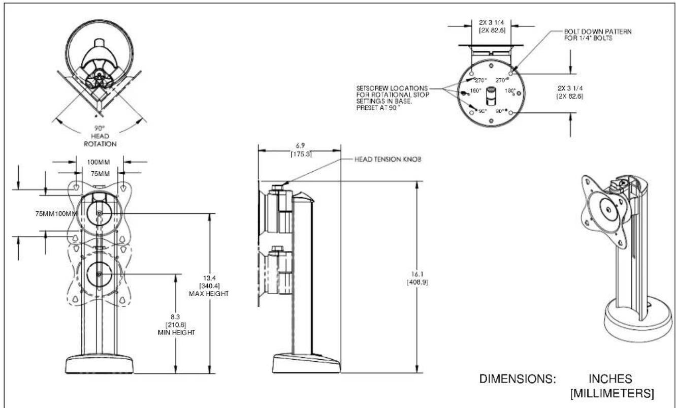
DIMENSIONS
text_image
90° HEAD ROTATION 100MM 75MM 75MM100MM 8.3 [210.8] MIN HEIGHT 13.4 [340.4] MAX HEIGHT 6.9 [175.3] HEAD TENSION KNO8 16.1 [408.9] 2X 3 1/4 [2X 82.6] BOLT DOWN PATTERN FOR 1/4" BOLTS 270° 270° 160° 180° 90° 90° 2X 3 1/4 [2X 82.6] DIMENSIONS: INCHES [MILLIMETERS]LEGEND
 | Tighten Fastener |  | Pencil Mark |
| Apretar elemento de fijación | Marcar con lápiz | ||
| Befestigungsteil festziehen | Stiftmarkierung | ||
| Apertar fixador | Marcar com lápis | ||
| Serrare il fissaggio | Segno a matita | ||
| Bevestiging vastdraaien | Potloodmerkteken | ||
| Serrez les fixations | Marquage au crayon | ||
 | Loosen Fastener |  | Drill Hole |
| Aflojar elemento de fijación | Perforar | ||
| Befestigungsteil lösen | Bohrloch | ||
| Desapertar fixador | Fazer furo | ||
| Allentare il fissaggio | Praticare un foro | ||
| Bevestiging losdraaien | Gat boren | ||
| Desserrez les fixations | Percez un trou | ||
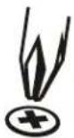 | Phillips Screwdriver |  | Adjust |
| Destornillador Phillips | Ajustar | ||
| Kreuzschlitzschraubendreher | Einstellen | ||
| Chave de fendas Phillips | Ajustar | ||
| Cacciavite a stella | Regolare | ||
| Kruiskopschroevendraaier | Afstellen | ||
| Tournevis à pointe cruciforme | Ajuster | ||
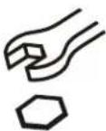 | Open-Ended Wrench |  | Remove |
| Llave de boca | Quitar | ||
| Gabelschlüssel | Entfernen | ||
| Chave de bocas | Remover | ||
| Chiave a punte aperte | Rimuovere | ||
| Steeksleutel | Verwijderen | ||
| Clé à fourche | Retirez | ||
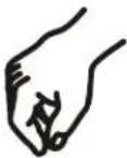 | By Hand |  | Optional |
| A mano | Opcional | ||
| Von Hand | Optional | ||
| Com a mão | Opcional | ||
| A mano | Opzionale | ||
| Met de hand | Optie | ||
| À la main | En option | ||
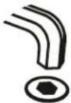 | Hex-Head Wrench |  | Security Wrench |
| Llave de cabeza hexagonal | Llave de seguridad | ||
| Sechskantschlüssel | Sicherheitsschlüssel | ||
| Chave de cabeça sextavada | Chave de segurança | ||
| Chiave esagonale | Chiave di sicurezza | ||
| Zeskantsleutel | Veiligheidssleutel | ||
| Clé à tête hexagonale | Clé de sécurité |
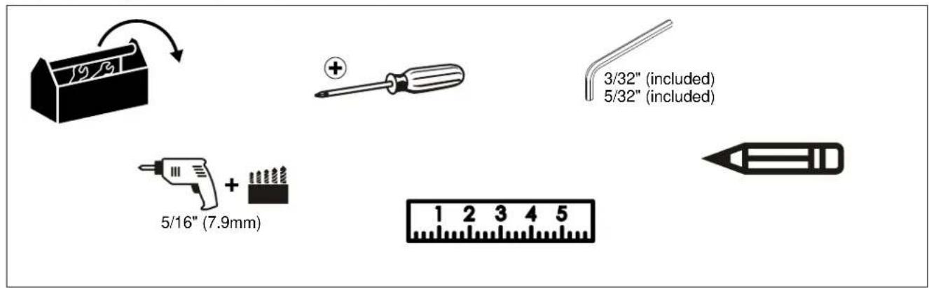
TOOLS REQUIRED FOR INSTALLATION
text_image
19/3 + 3/32" (included) 5/32" (included) 5/16" (7.9mm) 1 2 3 4 5PARTS
text_image
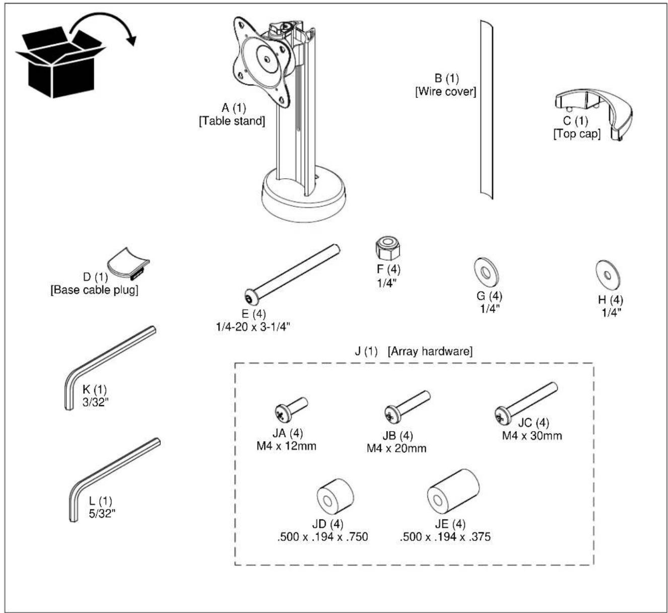
A (1) [Table stand] B (1) [Wire cover] C (1) [Top cap] D (1) [Base cable plug] E (4) 1/4-20 x 3-1/4" F (4) 1/4" G (4) 1/4" H (4) 1/4" J (1) [Array hardware] K (1) 3/32" L (1) 5/32" JA (4) M4 x 12mm JB (4) M4 x 20mm JC (4) M4 x 30mm JD (4) .500 x .194 x .750 JE (4) .500 x .194 x .375INSTALLATION
Site Preparation

WARNING: EXCEEDING WEIGHT CAPACITY CAN RESULT IN SERIOUS PERSONAL INJURY OR DAMAGE TO EQUIPMENT! It is the installer's responsibility to make sure the combined weight of all components attached to the STS1 up to (and including) the display does not exceed 30 lbs (13.6 kg).

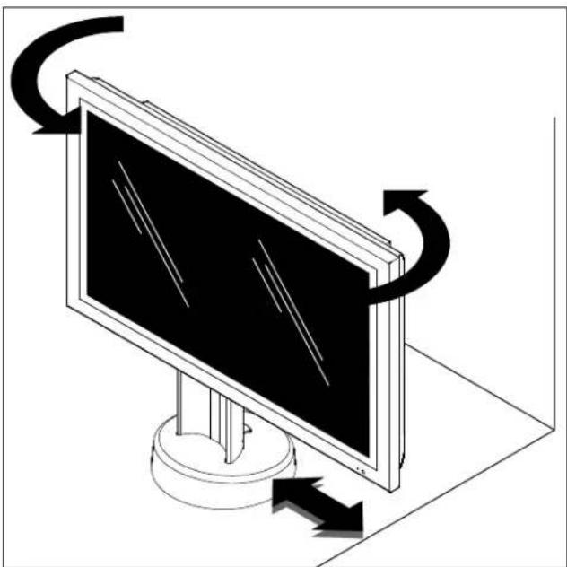
WARNING: TURNING DISPLAY CAN CAUSE DAMAGE TO SURROUNDING OBJECTS. Make certain location provides enough area for the display to rotate ±270^ without being obstructed, or lock display to a lesser rotation before rotating for the first time.
natural_image
Illustration of a computer monitor with curved arrows indicating rotation or motion (no text or symbols)Figure 1
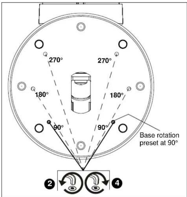
IMPORTANT ! : The STS1 is shipped with the display rotation set at the minimum of 90°. Base rotation may be adjusted to 90°, 180° or 270° and locked if installation location requires it. (See Figure 2)
Display head rotation may be adjusted in any increment between 0° and 90°.
Setting Rotation Limits
- Base rotation is factory-set at 90° but may be changed to 180° or 270° to allow necessary rotation. (See Figure 1)
- Remove and save setscrews from two 90° holes in base using 3/32" hex key (K). (See Figure 2)
- Determine amount of rotation required in installation.
- Place setscrews into the appropriate holes (180° or 270°) and tighten to secure rotation amount. (See Figure 2)
text_image
270° 270° 180° 180° 90° 90° Base rotation preset at 90° ② ④Figure 2
Attaching STS1 to Mounting Surface
- Locate a flat surface (thickness of 3/4" minimum to 2-1/2" maximum) on which to mount the STS1 assembly.
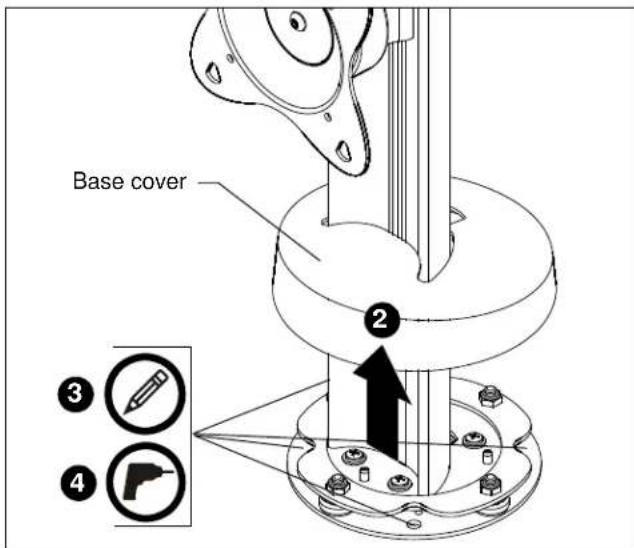
- Carefully raise STS1 base cover and affix to STS1 column using a piece of tape. (See Figure 3)
- Mark four mounting hole locations on mounting surface. (See Figure 3)
text_image
Base cover ② ③ ④Figure 3
-
Drill four 5/16" diameter (7.9mm) holes through mounting surface at marks, and an optional 1-5/8" diameter (41.3mm) cable management hole. (See Figure 3)
-
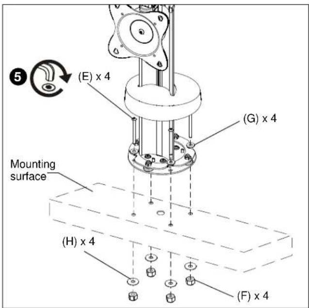
Attach STS1 to mounting surface using 5/32" hex key (L) and four 1/4-20 x 3-1/4" button head cap screws (E), four flat 1/4" flat washers (G), four 1/4" fender washer (H), and four 1/4" Nylock nuts (F). (See Figure 4)
- Lower STS1 base cover.
text_image
(E) x 4 (G) x 4 Mounting surface (H) x 4 (F) x 4Figure 4
Attaching Display

WARNING: IMPROPER INSTALLATION CAN LEAD TO DISPLAY FALLING CAUSING SERIOUS PERSONAL INJURY OR DAMAGE TO EQUIPMENT! Using screws of improper size may damage your display. Properly sized screws will easily and completely thread into display mounting holes. If spacers are required, be sure to use longer screws of the same diameter.
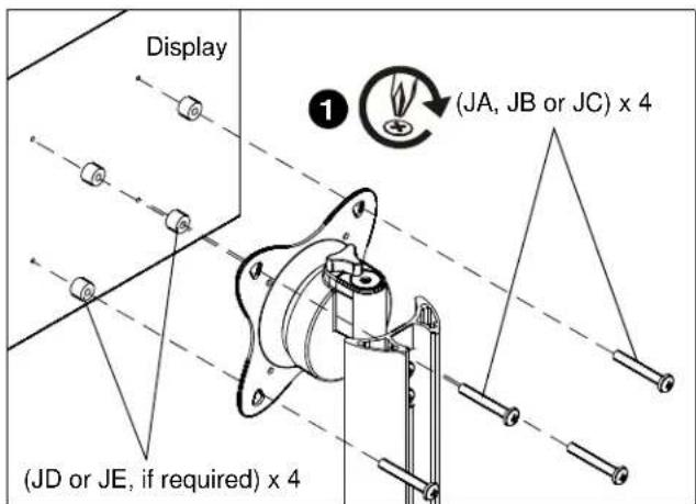
- Select correct screws, spacers (if necessary) from the hardware bag (J) and attach STS1 to back of display. (See Figure 5)
text_image
Display (JA, JB or JC) x 4 (JD or JE, if required) x 4Figure 5
Cable Management
- Run power cables from display to the back of the STS1.
- Lay power cables down back and through bottom of STS1, and through mounting surface.
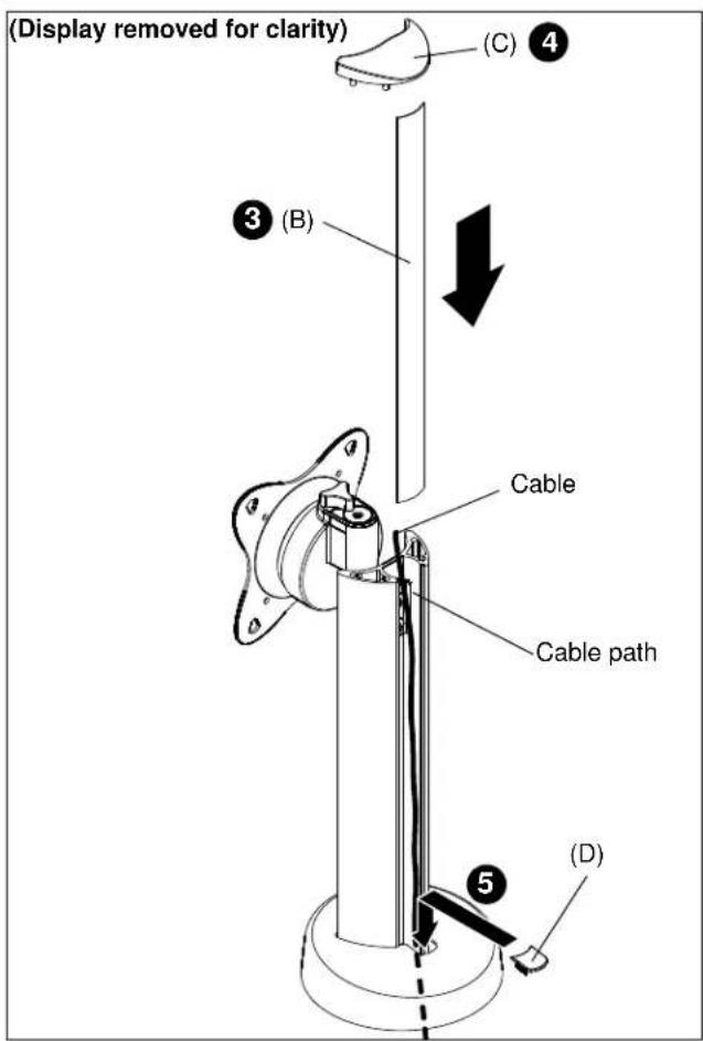
- Add wire cover (B) to back of STS1 by sliding it into the STS1 through the top. (See Figure 6)
- Add top cap (C) to top of STS1. (See Figure 6)
- Add base cable plug (D) to STS1 base. (See Figure 6)
text_image
(Display removed for clarity) (C) ④ ③ (B) Cable Cable path (D)Figure 6
Adjustments
Rotating Display
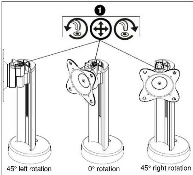
- The display may be rotated up to 90° on the STS1 head by using the 5/32" hex key (L) to loosen the fastener, rotating the head in either direction, and tightening the fastener. (See Figure 7)
text_image
1 45° left rotation 0° rotation 45° right rotationFigure 7
Display Roll, Pitch, Yaw Tension
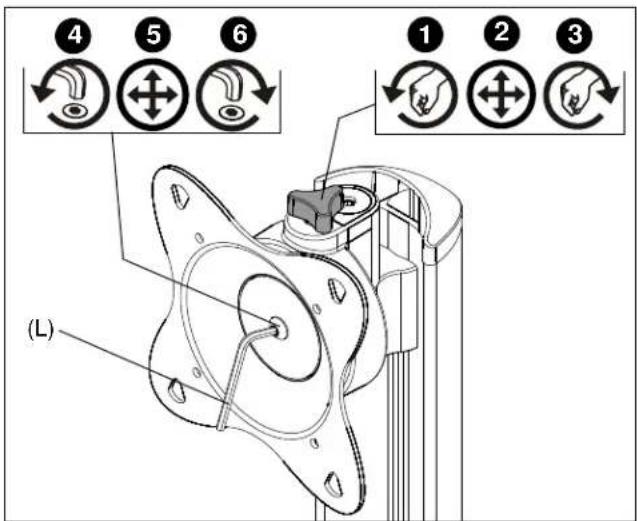
The display roll, pitch and yaw tension can be adjusted either using the tension adjustment knob, or the hex fastener on the head assembly.
• Tension Adjustment Knob
- Turn the tension adjustment knob counter-clockwise to decrease tension. (See Figure 8)
- Adjust STS1 head and display as required.
- Turn adjustment knob clockwise to increase tension.
text_image
(L) 1 2 3 4 5 6Figure 8
• Head Assembly Hex Fastener
- Loosen the head assembly hex fastener using the 5/32" hex key (L) to decrease tension. (See Figure 8)
- Adjust STS1 head as required.
- Tighten head assembly hex fastener to increase tension.
Raising/Lowering Display
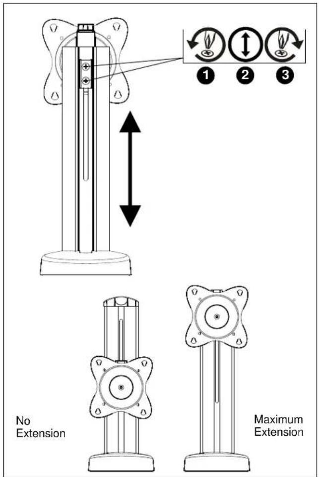
- Loosen, but do not remove, two Phillips head screws on back of STS1 assembly. (See Figure 9)
- Adjust display and head assembly to necessary height.
- Tighten two Phillips head screws on back of STS1 assembly. (See Figure 9)
text_image
1 2 3 No Extension Maximum ExtensionFigure 9
CLAUSE DE NON-RESPONSABILITÉ
natural_image
Illustration of a computer monitor with curved arrows indicating rotation or motion (no text or symbols)Figure 1
Our Mounts. Your Vision.
Chief, a products division of Milestone AV Technologies
8800-002857 Rev00
©2016 Milestone AV Technologies
www.milestone.com
07/16
USA/International A 6436 City West Parkway, Eden Prairie, MN 55344
P 800.582.6480 / 952.225.6000
F 877.894.6918 / 952.894.6918
Europe A Franklinstraat 14, 6003 DK Weert, Netherlands
P +31 (0) 495 580 852
F +31 (0) 495 580 845
Asia Pacific A Office No. 918 on 9/F, Shatin Galleria
18-24 Shan Mei Street
Fotan, Shatin, Hong Kong
P 852 2145 4099
F 852 2145 4477