
VCM35B - Flat screen mount Chief - Free user manual and instructions
Find the device manual for free VCM35B Chief in PDF.
| Product Type | Projector Mount |
| Brand | Chief |
| Model | VCM35B |
| Intended Use | Mounting projector to ceiling or column |
| Mounting Method | Attaches to NPT/NPSM 1-1/2" threaded extension column or low-profile mounting kit LPK-1 |
| Maximum Weight Capacity | 113.4 kg (250 lbs) |
| Horizontal Adjustment | Up to 38 mm (1-1/2") in all directions |
| Tilt Adjustment (Vertical) | Yes, by loosening outer bolts |
| Roll Adjustment (Horizontal Tilt) | Yes, via adjustment bolts |
| Column Compatibility | NPT or NPSM 1-1/2", aluminum series 40, minimum wall thickness 0.154" (ASTM B221) |
| Kit Compatibility | Chief UL-listed LPK-1 |
| Material | Aluminum (column), steel (mount) |
| Safety Instructions | Included in the manual |
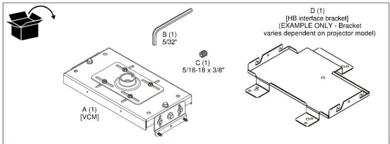
| Included Accessories | HB interface mounting bracket, leveling screws, nuts |
| Warranty | Consult the manufacturer |
| Manufacturer | Milestone AV Technologies |
Frequently Asked Questions - VCM35B Chief
User questions about VCM35B Chief
0 question about this device. Answer the ones you know or ask your own.
Ask a new question about this device
Download the instructions for your Flat screen mount in PDF format for free! Find your manual VCM35B - Chief and take your electronic device back in hand. On this page are published all the documents necessary for the use of your device. VCM35B by Chief.
USER MANUAL VCM35B Chief
Milestone AV Technologies and its affiliated corporations and subsidiaries (collectively "Milestone"), intend to make this manual accurate and complete. However, Milestone makes no claim that the information contained herein covers all details, conditions or variations, nor does it provide for every possible contingency in connection with the installation or use of this product. The information contained in this document is subject to change without notice or obligation of any kind. Milestone makes no representation of warranty, expressed or implied, regarding the information contained herein. Milestone assumes no responsibility for accuracy, completeness or sufficiency of the information contained in this document.
Chief® is a registered trademark of Milestone AV Technologies. All rights reserved.

IMPORTANT SAFETY INSTRUCTIONS

WARNING: A WARNING alerts you to the possibility of serious injury or death if you do not follow the instructions.

CAUTION: A CAUTION alerts you to the possibility of damage or destruction of equipment if you do not follow the corresponding instructions.

WARNING: Failure to read, thoroughly understand, and follow all instructions can result in serious personal injury, damage to equipment, or voiding of factory warranty! It is the installer's responsibility to make sure all components are properly assembled and installed using the instructions provided.

WARNING: Failure to provide adequate structural strength for this component can result in serious personal injury or damage to equipment! It is the installer's responsibility to make sure the structure to which this component is attached can support five times the combined weight of all equipment. Reinforce the structure as required before installing the component.

WARNING: Exceeding the weight capacity can result in serious personal injury or damage to equipment! It is the installer's responsibility to make sure the combined weight of all components located between the supporting structure and the VCM does not exceed 250 lbs (113.4 kg).
- The weight capacity of the VCM may be LIMITED to the lowest weight capacity of any other component located between the VCM and the supporting structure!

WARNING: Use this mounting system only for its intended use as described in these instructions. Do not use attachments not recommended by the manufacturer.

WARNING: Never operate this mounting system if it is damaged. Return the mounting system to a service center for examination and repair.

WARNING: Do not use this product outdoors.
IMPORTANT ! : The VCM mount is designed to be mounted to:
a 1-1/2" NPT or NPSM following ANSI/ASME B1.20.1 (Schedule 40, 0.154" minimum thickness aluminum-ASTM B221) threaded extension column;
- a UL Listed Chief LPK-1 low profile mounting kit.
--SAVE THESE INSTRUCTIONS--
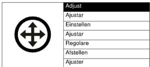
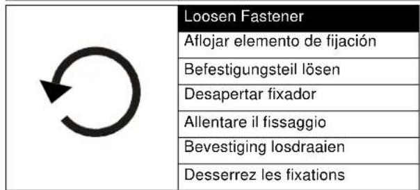
LEGEND
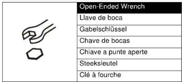
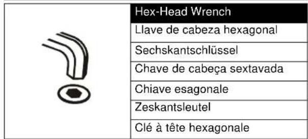
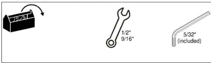
TOOLS REQUIRED FOR INSTALLATION
PARTS
INSTALLATION
The VCM mount is designed to be mounted to:
a 1-1/2" NPT or NPSM following ANSI/ASME B1.20.1 (Schedule 40, 0.154" minimum thickness aluminum-ASTM B221) threaded extension column; or
- a UL Listed Chief LPK-1 low profile mounting kit.
NOTE: Proceed to Installing VCM Mount to NPT Extension Column section or Installing VCM Mount to LPK-1 Mount Kit section, as appropriate.
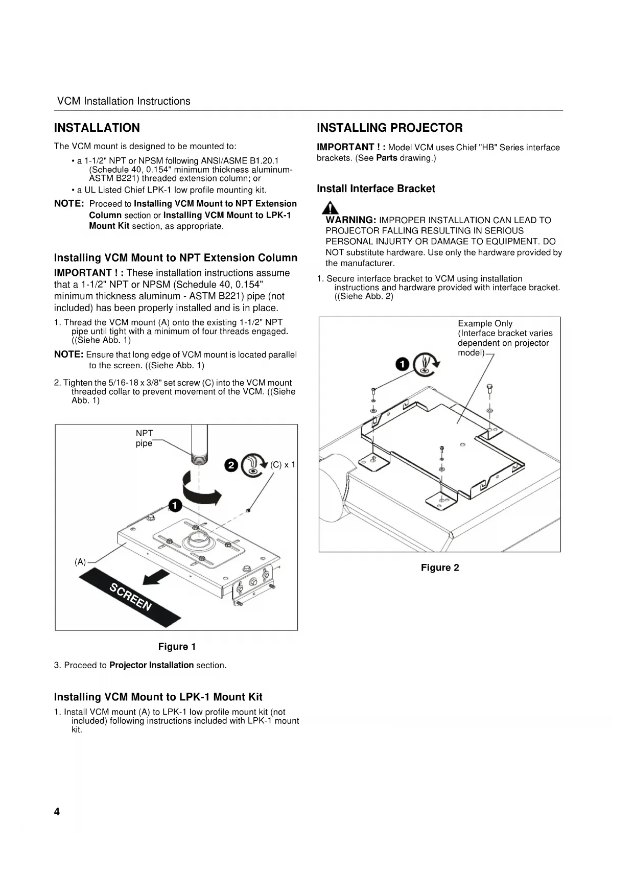
Installing VCM Mount to NPT Extension Column
IMPORTANT ! : These installation instructions assume that a 1-1/2" NPT or NPSM (Schedule 40, 0.154" minimum thickness aluminum - ASTM B221) pipe (not included) has been properly installed and is in place.
- Thread the VCM mount (A) onto the existing 1-1/2" NPT pipe until tight with a minimum of four threads engaged. ((Siehe Abb. 1)
NOTE: Ensure that long edge of VCM mount is located parallel to the screen. (Siehe Abb. 1) - Tighten the 5/16-18 x 3/8" set screw (C) into the VCM mount threaded collar to prevent movement of the VCM. ((Siehe Abb. 1)
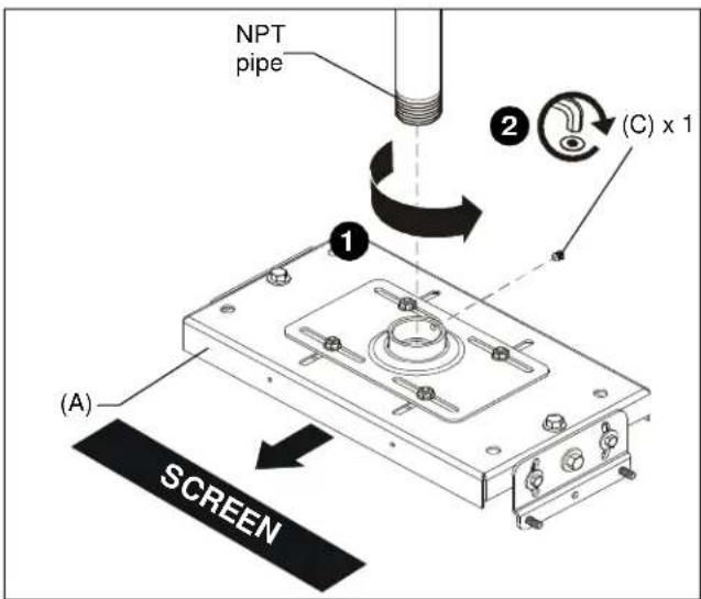
Figure 1
- Proceed to Projector Installation section.
Installing VCM Mount to LPK-1 Mount Kit
- Install VCM mount (A) to LPK-1 low profile mount kit (not included) following instructions included with LPK-1 mount kit.
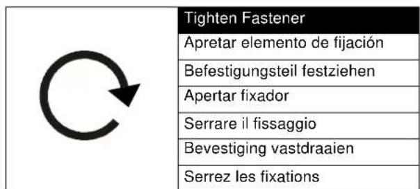
INSTALLING PROJECTOR
IMPORTANT !: Model VCM uses Chief "HB" Series interface brackets. (See Parts drawing.)
Install Interface Bracket

WARNING: IMPROPER INSTALLATION CAN LEAD TO PROJECTOR FALLING RESULTING IN SERIOUS PERSONAL INJURY OR DAMAGE TO EQUIPMENT. DO NOT substitute hardware. Use only the hardware provided by the manufacturer.
- Secure interface bracket to VCM using installation instructions and hardware provided with interface bracket. ((Siehe Abb. 2)
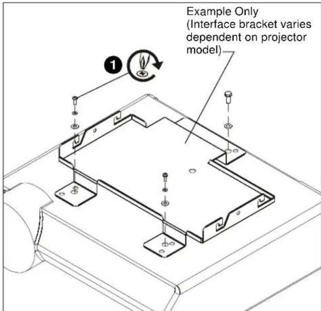
Figure 2
Install Locator with Attached Interface Bracket
- Orient projector with attached interface bracket so that it is square to the screen. ((Siehe Abb. 3)
- Lift the projector and install it to the four studs extending from the VCM housing. (Siehe Abb. 3)

WARNING: IMPROPER INSTALLATION CAN LEAD TO PROJECTOR FALLING RESULTING IN SERIOUS PERSONAL INJURY OR DAMAGE TO EQUIPMENT! Ensure that the VCM housing is seated in slots on HB bracket!
3. Tighten the four 5 / 16'' flange nuts. (Siehe Abb. 3)
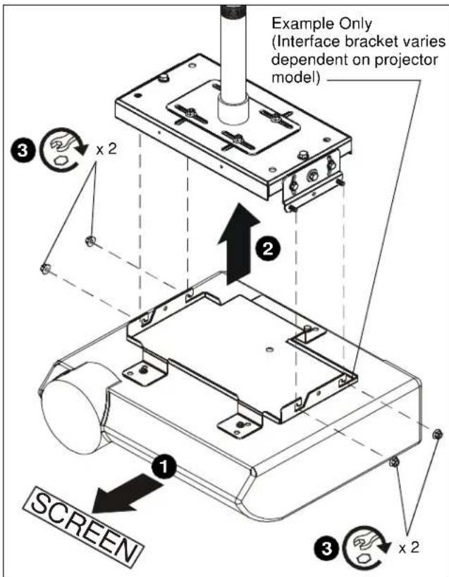
Figure 3
Adjustments

WARNING: MOUNTING HARDWARE IS TO BE LOOSEND ONLY ENOUGH TO ALLOW FOR NECESSARY MOVEMENT. Over-loosening or removal of mounting hardware may result in personal injury or serious damage to equipment!
- Loosen, but do NOT remove, the four nuts holding the top slide bracket on the VCM mount.
- Adjust VCM mount up to 1-1/2" in any direction.
- Tighten the nuts loosened (in Step 1) on the top slide bracket.

Figure 4
- Loosen three bolts on each end of the VCM mount.
-
Turn adjustment bolts (one at each end of VCM mount top) as required.
-
Turn CLOCKWISE to raise
-
Turn COUNTERCLOCKWISE to lower
-
Securely tighten three bolts on each end of VCM mount.

Figure 5
-
Loosen two outside bolts on each end of the VCM mount.
-
Tilt projector to desired direction.
-
Securely tighten two outside bolts on each end of VCM mount.
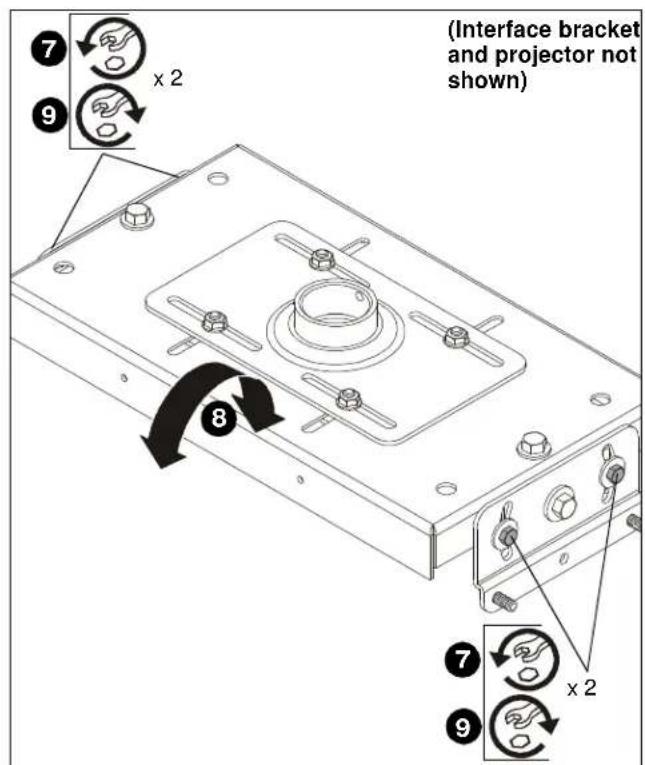
Figure 6
CLAUSES DE NON-RESPONSABILITÉ
- IMPORTANT SAFETY INSTRUCTIONS
- --SAVE THESE INSTRUCTIONS--
- LEGEND
- TOOLS REQUIRED FOR INSTALLATION
- PARTS
- INSTALLATION
- Installing VCM Mount to NPT Extension Column
- Installing VCM Mount to LPK-1 Mount Kit
- INSTALLING PROJECTOR
- Install Interface Bracket
- Install Locator with Attached Interface Bracket
- Adjustments
- CLAUSES DE NON-RESPONSABILITÉ
Brand : Chief
Model : VCM35B
Category : Flat screen mount