
RSMEUW - Flat screen mount Chief - Free user manual and instructions
Find the device manual for free RSMEUW Chief in PDF.
| Product Type | Projector Mount |
| Brand | Chief |
| Model | RSMEUW |
| Maximum Load Capacity | 11.34 kg (25 lbs) |
| Material | Steel |
| Installation Options | NPT/NPSM 1-1/2" threaded column, 2x4 wood studs, concrete ceiling (min. thickness 203 mm), #10-24 threaded rods |
| Adjustments | Yaw, Tilt, Roll |
| Adjustment Type | Micro-adjustment with locking screw |
| Locking System | Locking lever and key lock |
| Compatibility | Projectors with Chief SLB interface brackets |
| Required Tools | Phillips #2 screwdriver, socket wrench, drill |
| Optional Accessories | All-Points Security Kit, SLB interface bracket |
| Maintenance | Clean with a soft dry cloth |
| Safety | Structural support 5x weight, do not exceed maximum load |
Frequently Asked Questions - RSMEUW Chief
User questions about RSMEUW Chief
0 question about this device. Answer the ones you know or ask your own.
Ask a new question about this device
Download the instructions for your Flat screen mount in PDF format for free! Find your manual RSMEUW - Chief and take your electronic device back in hand. On this page are published all the documents necessary for the use of your device. RSMEUW by Chief.
USER MANUAL RSMEUW Chief
Milestone AV Technologies, and its affiliated corporations and subsidiaries (collectively, "Milestone"), intend to make this manual accurate and complete. However, Milestone makes no claim that the information contained herein covers all details, conditions or variations, nor does it provide for every possible contingency in connection with the installation or use of this product. The information contained in this document is subject to change without notice or obligation of any kind. Milestone makes no representation of warranty, expressed or implied, regarding the information contained herein. Milestone assumes no responsibility for accuracy, completeness or sufficiency of the information contained in this document.
Chief® is a registered trademark of Milestone AV Technologies. All rights reserved.

IMPORTANT SAFETY INSTRUCTIONS

WARNING: A WARNING alerts you to the possibility of serious injury or death if you do not follow the instructions.

CAUTION: A CAUTION alerts you to the possibility of damage or destruction of equipment if you do not follow the corresponding instructions.

WARNING: Failure to read, thoroughly understand, and follow all instructions can result in serious personal injury, damage to equipment, or voiding of factory warranty! It is the installer's responsibility to make sure all components are properly assembled and installed using the instructions provided.

WARNING: Failure to provide adequate structural strength for this component can result in serious personal injury or damage to equipment! It is the installer's responsibility to make sure the structure to which this component is attached can support five times the combined weight of all equipment. Reinforce the structure as required before installing the component.

WARNING: Exceeding the weight capacity can result in serious personal injury or damage to equipment! It is the installer's responsibility to make sure the combined weight of all components attached to the RSME does not exceed 25 lbs (11.34 kg).
- The weight capacity of the RSME may be LIMITED to the lowest weight capacity of any other components located between the RSME and the supporting structure!

WARNING: Use this mounting system only for its intended use as described in these instructions. Do not use attachments not recommended by the manufacturer.

WARNING: Never operate this mounting system if it is damaged. Return the mounting system to a service center for examination and repair.

WARNING: Do not use this product outdoors.
IMPORTANT ! : The RSME mounts are designed to be:
- mounted to a 1-1/2" NPT or NPSM steel or aluminum threaded extension column rated for 50 lbs or greater (not included); or
- mounted to double 2'' × 4'' wood stud cross bracing (1-1/2" on center) between two 2'' × 4'' ceiling joists; with a maximum drywall covering of 5/8' .
- mounted to a concrete ceiling with a minimum thickness of 8'' and a maximum drywall covering of 5/8'' ; or
- suspended from four steel #10-24 threaded rods (not included) which are secured to a 1-5/8" x 1-5/8" 12ga metal framing strut channel (spanning a maximum of 4 feet--not included) by #10-24 channel nuts (not included).
--SAVE THESE INSTRUCTIONS--
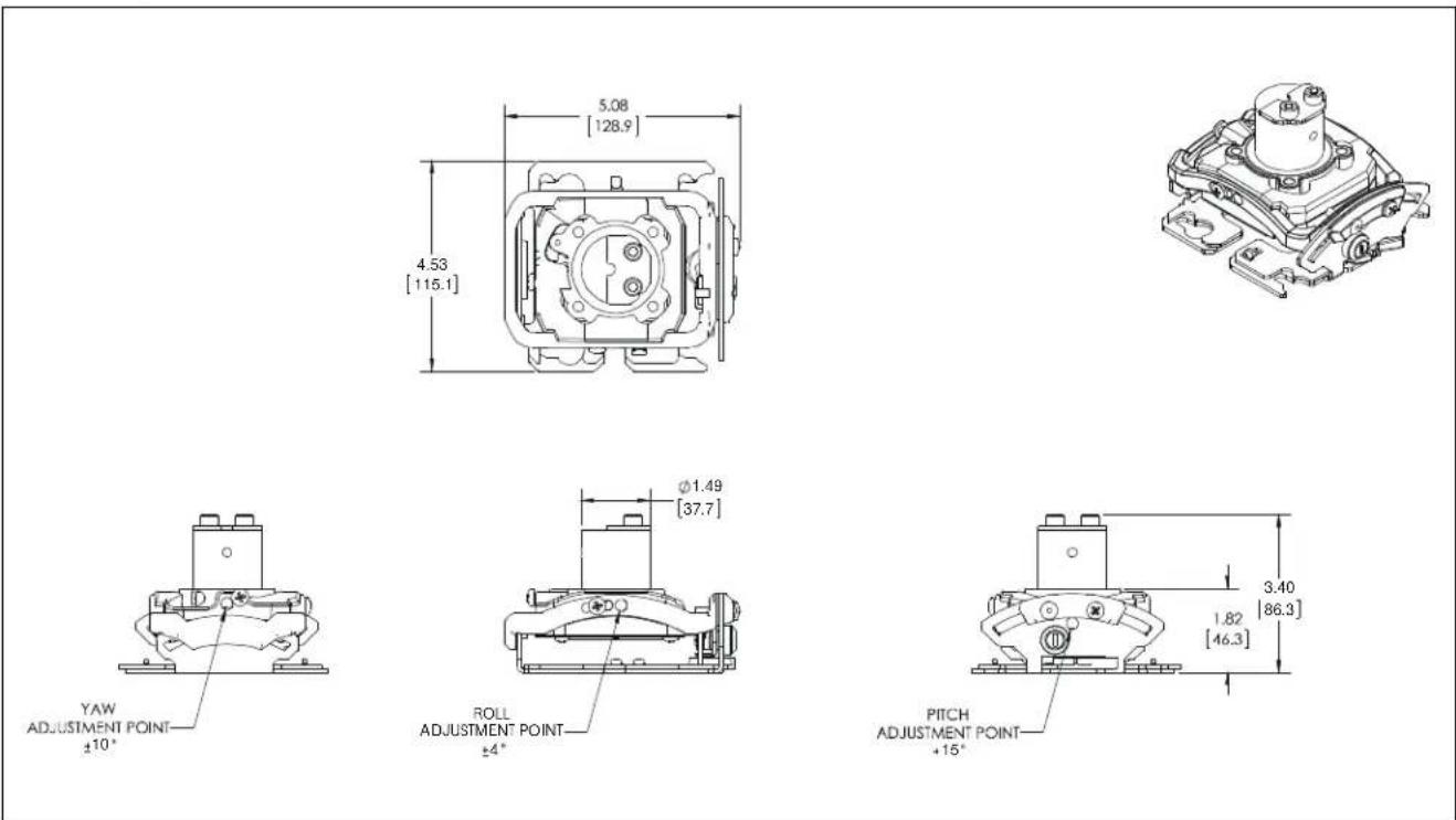
DIMENSIONS
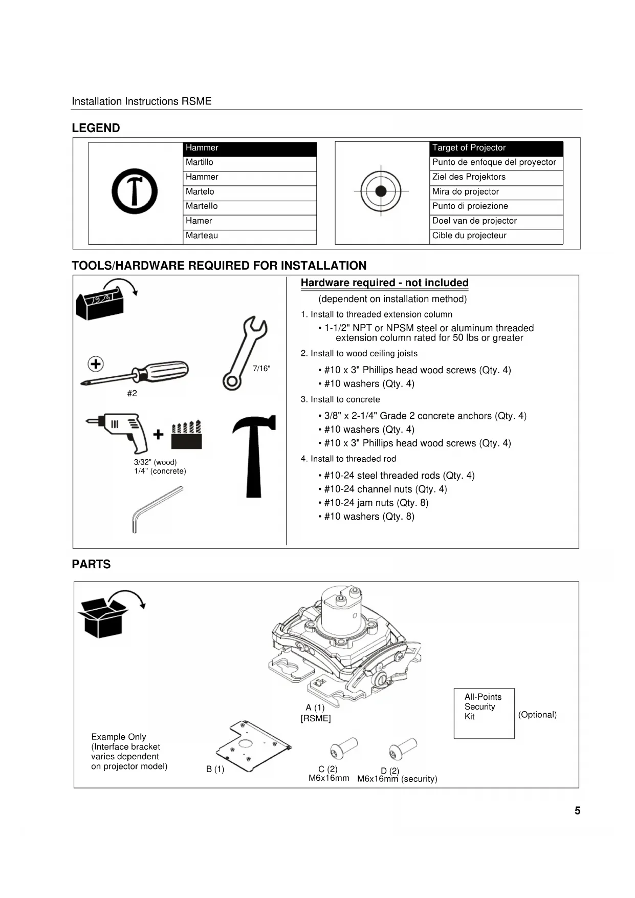
LEGEND
| Tighten Fastener Serrez les fixations Serrare il fissaggio Befestigungsteil festziehen Aprotar elemento de fijación Bevestiging vastdraaien Apertar fixador | Pencil Mark Marquage au crayon Segno a matita Stiftmarkierung Marcar con lápiz Potloodmerkteken Marcar com lápis |
| Loosen Fastener Desserrez les fixations Allentare il fissaggio Befestigungsteil lösen Aflojar elemento de fijación Bevestiging losdraaien Desapertar fixador | Drill Hole Percez un trou Praticare un foro Bohrloch Perforar Gat boren Fazer furo |
| Phillips Screwdriver Tournevis à pointecruciforme Cacciavite a stella Kreuzschlitzschraubendreher Destornillador Phillips Kruiskopschroeveendraier Chave de fendas Phillips | Adjust Ajuster Regolare Einstellen Ajuster Afstellen Ajuster |
| Hex-Head Wrench Clé à tête hexagonale Chiave esagonale Sechskantschlüssel Llave de cabeza hexagonal Zeskantsleutel Chave de cabeça sextavada | Remove Retirez Rimuovere Entfernen Quitar Verwijderen Remover |
| Open-End Wrench Clé à fourche Chiave a punte aperte Gabelschlüssel Llave de Boca Steeksleutel Chave de bocas | Optional En option Opzionale Optional Opcial Optie Optional |
| By Hand À la main A mano Von Hand A mano Met de hand Com a mão | Security Wrench Clé de sécurité Chiave di sicurezza Sicherheitschlüssel Llave de seguidad Veiligheidssleutel Chave de seguranca |
LEGEND
| Hammer | Target of Projector |
| Martillo | Punto de enfoque del projector |
| Hammer | Ziel des Projektors |
| Martelo | Mira do projector |
| Martello | Punto di proiezione |
| Hamer | Doel van de projector |
| Martreau | Cible du projecteur |
TOOLS/HARDWARE REQUIRED FOR INSTALLATION
| #2 3/32" (wood) 1/4" (concrete) | 7/16" | Hardware required - not included (dependent on installation method) 1. Install to threaded extension column ·1-1/2" NPT or NPSM steel or aluminum threaded extension column rated for 50 lbs or greater 2. Install to wood ceiling joists ·#10 x 3" Phillips head wood screws (Qty. 4) ·#10 washers (Qty. 4) 3. Install to concrete ·3/8" x 2-1/4" Grade 2 concrete anchors (Qty. 4) ·#10 washers (Qty. 4) ·#10 x 3" Phillips head wood screws (Qty. 4) 4. Install to threaded rod ·#10-24 steel threaded rods (Qty. 4) ·#10-24 channel nuts (Qty. 4) ·#10-24 jam nuts (Qty. 8) ·#10 washers (Qty. 8) |
PARTS
| A (1) [RSME] | All-Points Security Kit | (Optional) | ||
| Example Only (Interface bracket varies dependent on projector model) | B (1) | C (2) M6x16mm | D (2) M6x16mm (security) | |
RSME INSTALLATION
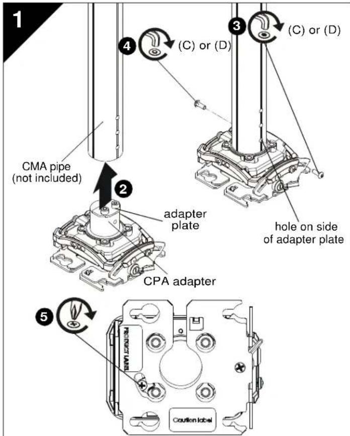
CPA Pipe Installation
- Carefully determine required mounting location.
IMPORTANT ! : This will require knowing the lens to screen distance. See projector specifications for details on determining this distance. - Making sure holes are aligned on RSME's CPA adapter and CPA column (not included), lift RSME into bottom opening of CPA column.
- Install either one M6x16 button head screw (C) or security screw (D) into hole on side of CPA pipe where the adapter plate on CPA adapter is located.
- On the opposite side of CPA pipe, use the other M6x16 button head screw (C) or security screw (D) to secure RSME (A) to CPA column.
- Tighten security screw (access from bottom of RSME) using a Phillips screwdriver until set screw cannot be seen through set screw access hole in RSME.
- Proceed to "Projector Installation" Section.
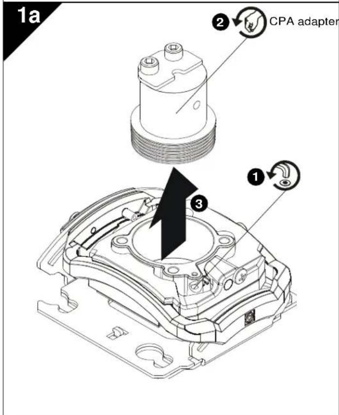
CPA Adapter Removal
NOTE: If installing RSME to anything other than a CPA column, the CPA adapter portion must be removed from RSME mount prior to installation.
- Loosen set screw holding CPA adapter to RSME mount.
- Turn CPA adapter counter-clockwise until threads are no longer engaged with RSME.
- Remove CPA adapter from RSME.
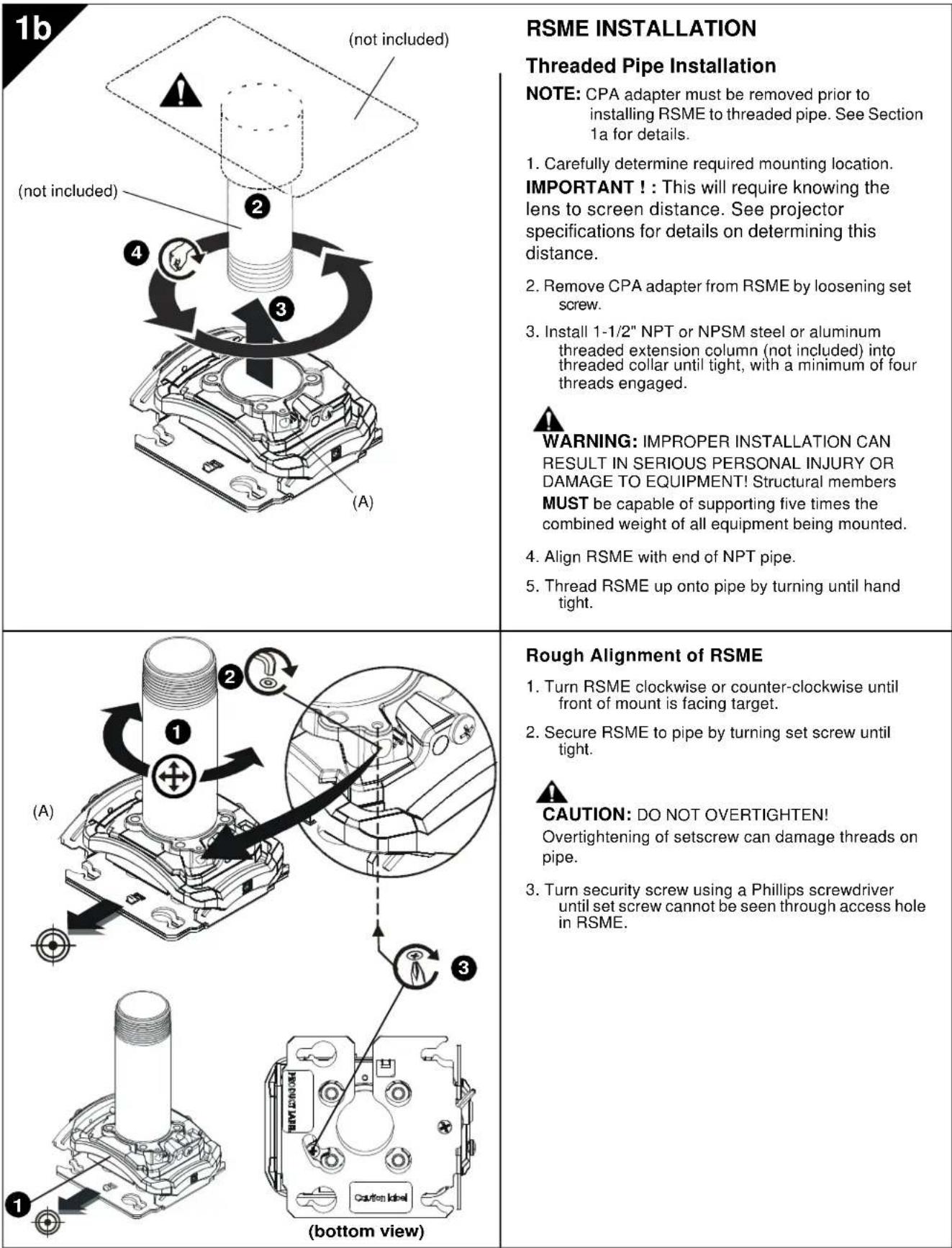
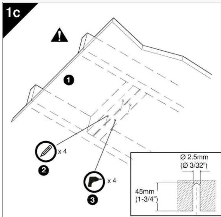
Wood Stud Installation
NOTE: CPA adapter must be removed prior to installing RSME to wood studs. See Section 1a for details.
- Carefully determine required mounting location.
IMPORTANT! : This will require knowing the lens to screen distance. See projector specifications for details on determining this distance.

WARNING: IMPROPER INSTALLATION CAN RESULT IN SERIOUS PERSONAL INJURY OR DAMAGE TO EQUIPMENT! Structural members MUST be capable of supporting five times the combined weight of all equipment being mounted.
IMPORTANT ! : The RSME mounts are designed to be mounted to double 2'' × 4'' wood stud cross bracing (1-1/2" on center) between two ceiling joists; with a maximum drywall covering of 5/8'' .
-
Using the RSME as a guide, mark four mounting hole locations with a pencil or similar tool. Hole locations must be centered on 2 × 4 cross braces.
-
Drill four 3/32" (2.5mm) dia. pilot holes to a depth of 1-3/4" (45mm) deep.
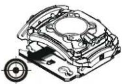
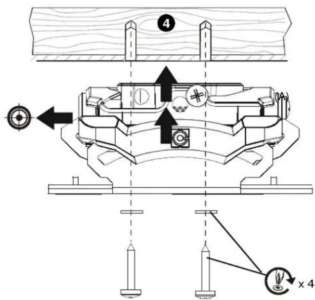
- Align four mounting holes in RSME with four pilot holes.
IMPORTANT! : Make sure mount is properly oriented towards target before securing to structure.
5. Secure RSME to structure using four #10 flat washers and four #10 x 3" Phillips head wood screws (not included).
1d
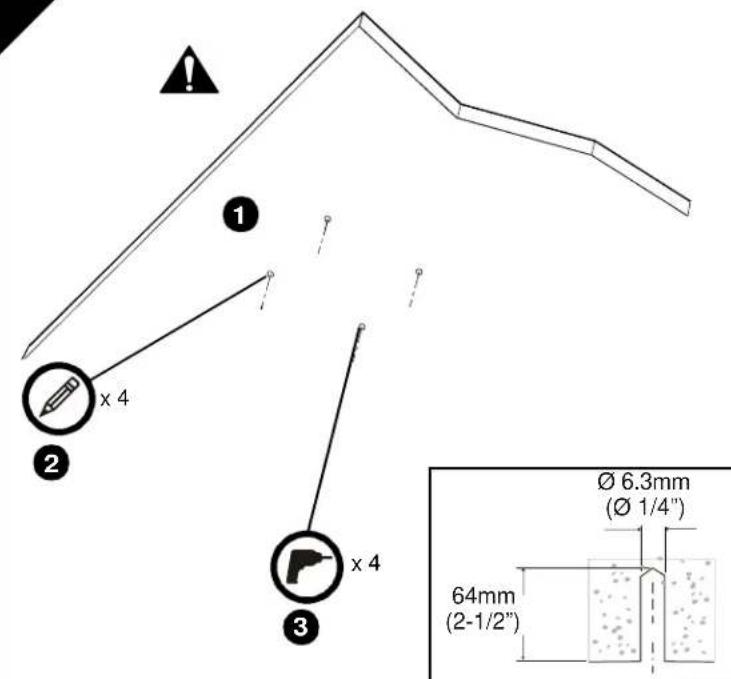
Concrete Installation
NOTE: CPA adapter must be removed prior to installing RSME to concrete. See Section 1a for details.
- Determine mounting location.

WARNING: The RSME is designed to be mounted to a concrete ceiling with a minimum thickness of 8 and a maximum drywall covering of 5 / 8 .

WARNING: IMPROPER INSTALLATION CAN RESULT IN SERIOUS PERSONAL INJURY OR DAMAGE TO EQUIPMENT! Structural members MUST be capable of supporting five times the combined weight of all equipment being mounted.
- Using the RSME as a guide, mark four mounting hole locations on ceiling using a pencil or similar tool.
- Drill four 1/4 (6.3mm) dia. pilot holes to a depth of 2-1/2" (64mm) deep.
- Align four mounting holes in RSME with four pilot holes.
IMPORTANT ! : Make sure mount is properly oriented towards target before securing to structure.

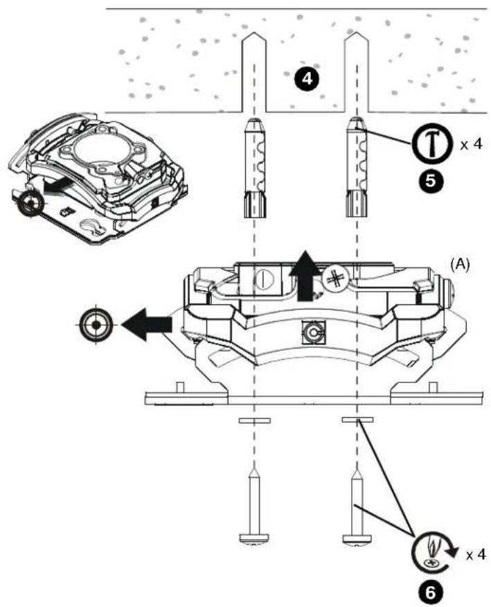
WARNING: Anchors (not provided) must be installed into structurally sound solid concrete. Installation into hollow concrete block, mortar, or concrete that exhibits cracking, spalling, or other defects may result in failure of anchor and serious personal injury or damage to equipment.
- Install four 3/8'' × 2-1/4'' concrete anchors (not included) by inserting into pilot holes and pounding in until flush with mounting surface.
- Secure RSME to structure using four #10 flat washers and four #10 x 3" Phillips head wood screws (not included).
| 1e A2 4 (A) 5 x 4 | Threaded Rod Installation NOTE: CPA adapter must be removed prior to installing RSME to threaded rods. See Section 1a for details. The RSME must be suspended from four #10-24 diameter (minimum) threaded rods (not included) which are secured to unistrut, angle or channel assembly overhead structural members (trusses or l-beams) #10-24 channel nuts (not included). WARNING: IMPROPER INSTALLATION CAN RESULT IN SERIOUS PERSONAL INJURY OR DAMAGE TO EQUIPMENT! Structural members MUST be capable of supporting five times the combined weight of all equipment being mounted. 1. Carefully determine required mount position. IMPORTANT ! : This will require knowing the lens to screen distance. See projector specifications for determining this distance. NOTE: Threaded rod and installation hardware not included. 2. Secure one end of the threaded rod to the structural member. 3. Install one #10-24 jam nut (not included) and one #10 washer on each threaded rod. 4. Install the RSME on the threaded rod. NOTE: Hole in the RSME allows socket wrench access without unit disassembly. 5. Secure the RSME to the threaded rod using four #10-24 nuts (not included) and four #10 washers (not included). |
| 2 Example Only (Interface bracket varies dependent on projector model) | PROJECTOR INSTALLATION IMPORTANT ! : Model RSME uses optional Chief "SSM" Series interface brackets. (See Parts drawing.) Install Interface Bracket 1. Partially thread thumb nuts onto Phillips screws until screw end is visible in top of thumb screw. IMPORTANT ! : DO NOT fully tighten thumb screws at this time. |
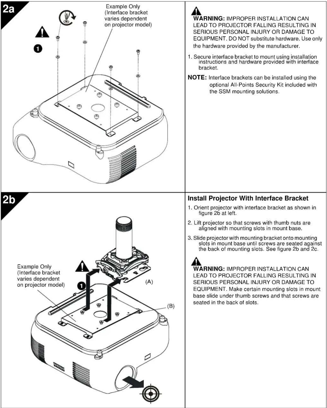
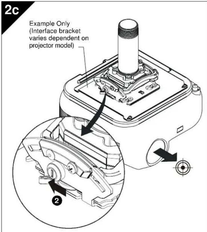
Securing Projector with Interface Bracket to Model RSME Mount

WARNING: IMPROPER INSTALLATION CAN LEAD TO PROJECTOR FALLING RESULTING IN SERIOUS PERSONAL INJURY OR DAMAGE TO EQUIPMENT. Make certain mounting slots in mount base slide under thumb screws and that screws are seated in the back of slots.
- Verify mounting screws are properly seated in mounting slots in mount base.
- Move locking lever to "Locked" position as shown in figure 2c at left.
- Insert key into lock and turn to secure projector to mount.
ADJUSTMENTS
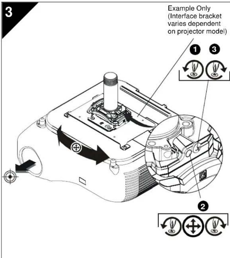
YAW Adjustment
- Loosen YAW adjustment locking screw using a #2 Phillips screwdriver.
- Turn YAW micro-adjustment screw right or left using a #2 Phillips screwdriver until image is properly aligned on target.
- Tighten YAW adjustment locking screw using a #2 Phillips screwdriver.
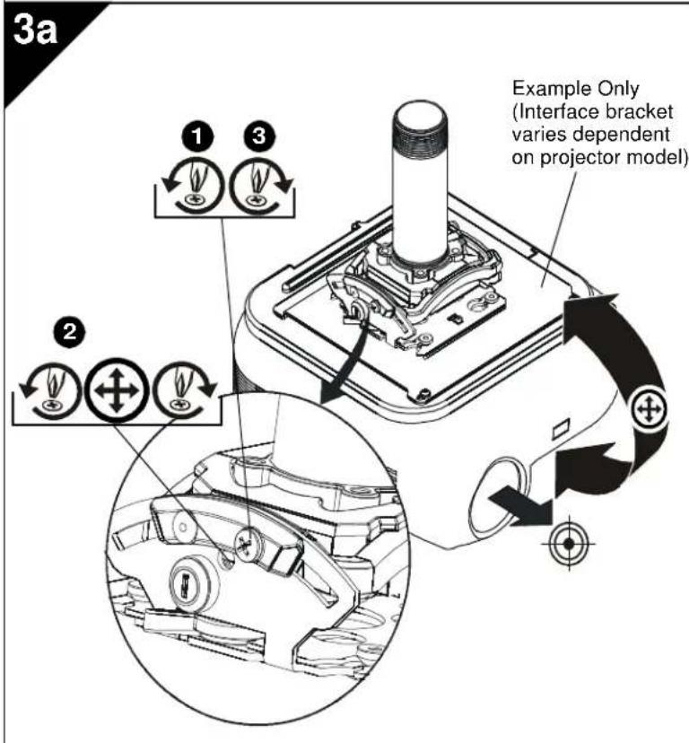
Pitch Adjustment
- Loosen PITCH adjustment locking screw using a #2 Phillips screwdriver.
- Turn PITCH micro-adjustment screw right or left using a #2 Phillips screwdriver until image is properly aligned on target.
- Tighten PITCH adjustment locking screw using a #2 Phillips screwdriver.
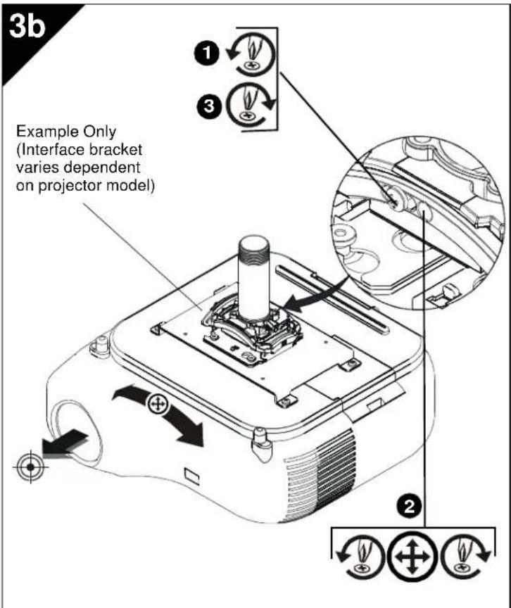
Roll Adjustment
- Loosen ROLL adjustment locking screw using a #2 Phillips screwdriver.
- Turn ROLL micro-adjustment screw right or left using a #2 Phillips screwdriver until image is properly aligned on target.
- Tighten ROLL adjustment locking screw using a #2 Phillips screwdriver.
CLAUSES DE NON-RESPONSABILITÉ
Installation Instructions
- IMPORTANT SAFETY INSTRUCTIONS
- SAVE THESE INSTRUCTIONS
- DIMENSIONS
- LEGEND
- TOOLS/HARDWARE REQUIRED FOR INSTALLATION
- PARTS
- RSME INSTALLATION
- CPA PIPE INSTALLATION
- CPA ADAPTER REMOVAL
- WOOD STUD INSTALLATION
- CONCRETE INSTALLATION
- SECURING PROJECTOR WITH INTERFACE BRACKET TO MODEL RSME MOUNT
- ADJUSTMENTS
- YAW ADJUSTMENT
- PITCH ADJUSTMENT
- ROLL ADJUSTMENT
- CLAUSES DE NON-RESPONSABILITÉ
Brand : Chief
Model : RSMEUW
Category : Flat screen mount