207W - Surveillance Camera AXIS - Free user manual and instructions
Find the device manual for free 207W AXIS in PDF.

User questions about 207W AXIS
0 question about this device. Answer the ones you know or ask your own.
Ask a new question about this device
Download the instructions for your Surveillance Camera in PDF format for free! Find your manual 207W - AXIS and take your electronic device back in hand. On this page are published all the documents necessary for the use of your device. 207W by AXIS.
USER MANUAL 207W AXIS
This installation guide provides instructions for installing the AXIS 207/207W/207MW Network Camera on your network. For all other aspects of using the product, please see the User's Manual, which is available on the CD included in this package, or from www-axis.com/techsup
Installation steps
- Check the package contents against the list below.
- Hardware overview. Familiarize yourself with the camera. See page 4.
- Install the hardware and make all cable connections. See page 7.
- Set an IP address. See page 8.
- Set the password. See page 12.
- Configure the wireless connection. See page 13.
- Adjust the focus. See page 15.
Important!
This product must be used in compliance with local laws and regulations.
1. Package contents
Item Models/variants/notes
Network camera AXIS 207
AXIS 207W
AXIS 207MW
Indoor power supply
AXIS 207: type PS-L
(country specific)
AXIS 207MW/AXIS 207W: type PS-H
Power supply extension
1.8 meters
cable
Camera stand Supplied with 3 mounting screws. The extension section is ready fitted.
Flexible clamp For shelf mounting
Terminal block connector 4-pin connector block for connecting external devices to the I/O terminal con- nector
Cable clip Self-adhesive - fixes to back panel for holding power cable
CD Axis Network Video Product CD, including installation tools and other software, product documentation
Printed Materials AXIS 207/207W/207MW Installation Guide (this document)
Axis Warranty Document
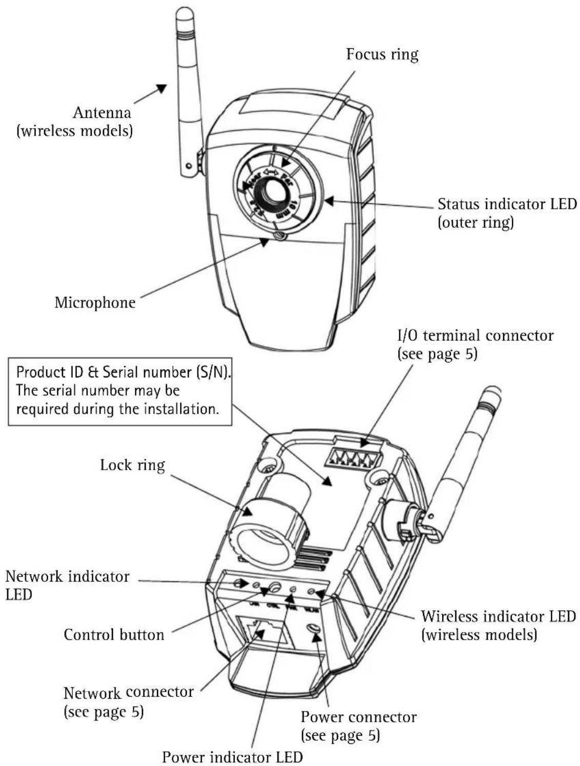
2. Hardware overview
Dimensions
AXIS 207: HxWxD = 85 × 55 × 34mm (3.3" × 2.2" × 1.3")
Weight = 177g (0.39 lb) (stand included, power supply excluded)
AXIS 207W/MW: HxWxD = 85 × 55 × 40mm (3.3" × 2.2" × 1.6") (antenna excluded)
Weight: 190g (0.42 lb) (stand included, power supply excluded)
Unit connectors
Network connector - RJ-45 Ethernet connector. Supports Auto-MDIX (AXIS 207W/MW only) for automatic detection of straight or crossover cable. Using shielded cables is recommended.
Power connector - Mini DC connector. 4.9-5.1V DC, max 4.0W. See product label for ± connection.
I/O terminal connector - Used in applications for e.g. motion detection, event triggering, time lapse recording, alarm notifications, etc. It provides the interface to:
- 1 transistor output - For connecting external devices such as relays and LED:s. Connected devices can be activated by Output buttons on the Live View page or by an Event Type. The output will show as active (in Event Configuration > Port Status) if the alarm device is activated.
- 1 digital input - An alarm input for connecting devices that can toggle between an open and closed circuit, for example: PIRs, door/window contacts, glass break detectors, etc. When a signal is received the state changes and the input becomes active (shown under Event Configuration > Port Status).
- Auxiliary power and GND
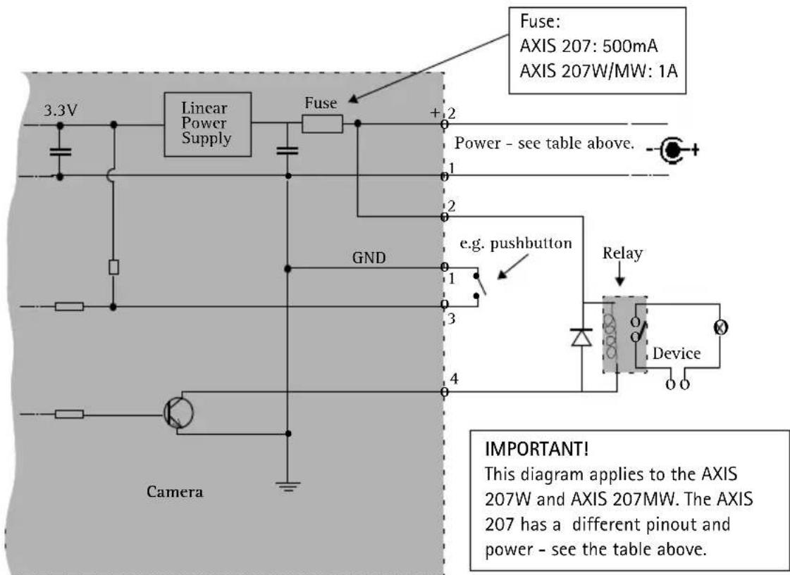
| Function | Pin number | Notes Specifications | |
| Transistor Output | Pin 4 Uses an open-collector NPN transistor with the emitter connected to the GND pin. If used with an external relay, a diode must be connected in parallel with the load, for protection against voltage transients. | Max load = 100mA Max voltage = 24V DC (to the transistor) | |
| Digital Input Pin 3 Connect to GND to activate, or leave floating (or unconnected) to deactivate. | Must not be exposed to voltages greater than 10V DC | ||
| GND AXIS 207 = Pin 2 AXIS 207W/MW = Pin 1 | Ground | ||
| Auxiliary DC Power Input | AXIS 207 = Pin 1 AXIS 207W/MW = Pin 2 | Electrically connected in parallel with the connector for the power supply, this pin provides an auxiliary connector for mains power to the unit. This pin can also be used to power auxiliary equipment, with a maximum current of 50mA. | Voltage = 4.9-5.1V DC (all models) Min power: AXIS 207: 2.5W AXIS 207W: 3.5W AXIS 207MW: 4.0W |
| Pin layouts AXIS 207 4 AXIS 207W AXIS 207W | 1 4 | ||
Connection diagram
LED indicators
| LED Color | Indication | |
| Wireless Unlit Wired mode. | ||
| Green Steady for connection to a wireless network. Flashes for network activity. | ||
| Red Steady for no wireless network connection. Flashes when scanning for wireless networks. | ||
| Network | Green | Steady for connection to a 100 Mbit/s network. Flashes for network activity. |
| Amber | Steady for connection to 10 Mbit/s network. Flashes for network activity. | |
| Unlit No wired network connection, or AXIS 207MW/AXIS 207W in wireless mode. | ||
| Status Green | Steady green | for normal operation.Note: The Status LED can be configured to be unlit during normal operation, or to flash only when the camera is accessed. To configure, go to Setup > System Options > LED settings. See the online help files for more information. |
| Amber Steady during startup, during reset to factory default or when restoring settings. | ||
| Red Slow flash for failed upgrade. | ||
| Power Green | Normal operation. | |
| Amber Flashes green/amber during firmware upgrade. | ||
3. Install the hardware
IMPORTANT! - The AXIS 207/207W/207MW is designed for indoor use only, and must always be positioned where it is not exposed to direct sunlight or strong halogen light, which can cause permanent damage to the camera's
image sensor. Damage as a result of exposure to strong light is not covered by the Axis warranty.
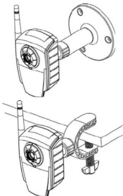
3a. Mount the camera
Make a note of the serial number (S/N) located on the product label. This number may be required during installation.
Wall mounting
- If required, use the 3 supplied screws to fix the base plate to a flat (horizontal or vertical) surface.
- To use a shorter stand, unscrew the lock ring to release the camera, and remove the extension section.
- Attach the camera, adjust the angle and tighten the lock ring.
Shelf mounting
- Position the clamp and tighten the fixing screw securely.
- Attach the clamp to the lock ring on the camera.
- Adjust the angle and tighten the lock ring.
3b. Connect the cables
- Using the self-adhesive strip, attach the supplied cable clip to the rear panel and fasten the power cable to it. This will prevent accidental cable disconnection.
- Connect the camera to the network using a shielded network cable. For the wireless models, this connection is temporary and allows the camera's settings to be configured via the wired network before connecting to the wireless network.
- Optionally connect external devices, e.g. alarm devices. See page 5 for information on the terminal connector pins.
-
Connect power, using one of the methods listed below:
-
Connect the supplied indoor power supply to the power connector on the camera.
-
Connect power via the terminal connector. See page 5 for information on the terminal connector pins.
-
Check that the indicator LED:s indicate the correct conditions. See the table on page 6 for further details. Note that some LED:s can be disabled and may be unlit.
4. Set an IP address
To make it accessible on the network, the AXIS 207/207W/207MW must be assigned an IP address.
Depending on the number of cameras you wish to install, the recommended method for setting IP addresses in Windows is either AXIS IP Utility or AXIS Camera Management. Use the method that best suits your purpose.
Both of these free applications are available on the Axis Network Video Product CD supplied with this product, or they can be downloaded from www-axis.com/techsup
| Method Recommended for Operating system | ||
| IP AXIS IP Utility See page 9. | Single cameras Small installations | Windows |
| AXIS Camera Management See page 10. | Multiple cameras Large installations Installations on other subnets | Windows 2000 Windows XP Pro Windows 2003 Server |
Notes:
- A network DHCP server is optional.
- The AXIS 207/207W/207MW has the default IP address 192.168.0.90
- If setting the IP address fails, check that there is no firewall blocking the operation.
- For other methods of setting or discovering the IP address of the AXIS 207/207W/207MW, e.g. in other operating systems, see page 11.
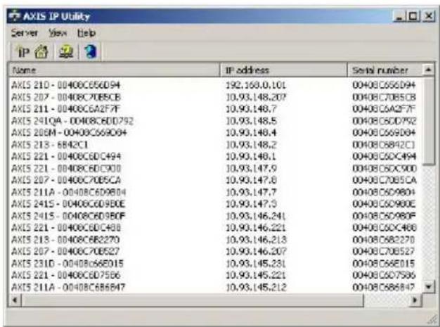
AXIS IP Utility - single camera/small installation
AXIS IP Utility automatically discovers and displays Axis devices on your network. The application can also be used to manually set a static IP address.
Note that the computer running AXIS IP Utility must be on the same network segment (physical subnet) as the AXIS 207/207W/207MW.
Automatic discovery
- Check that the AXIS 207/207W/ 207MW is connected to the network and that power has been applied.
-
Start AXIS IP Utility.
-
When the camera appears in the window, double-click it to open its home page.
-
See page 12 for instructions on how to set the password.
Set the IP address manually
- Acquire an unused IP address on the same network segment your computer is connected to.
- Click the button Set IP address using serial number and enter the serial number and IP address for the AXIS 207/207W/207MW. The serial number is located on the product label.
- Click the Set IP button and follow the instructions.
- Click View Home Page button to access the camera's web pages.
- See page 12 for instructions on how to set the password.

AXIS Camera Management - multiple cameras/large installations
AXIS Camera Management can automatically find and set IP addresses, show connection status, and manage firmware upgrades for multiple Axis video products.
Set the IP address for a single device
- Check that the camera is connected to the network and that power has been applied.
- Start AXIS Camera Management. When the AXIS 207/207W/
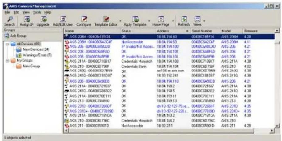
207MW appears in the window, double-click it to open the camera's home page.
- See page 12 for instructions on how to set the password.
Set the IP address in multiple devices
AXIS Camera Management speeds up the process of assigning IP addresses to multiple devices, by suggesting IP addresses from a specified range.
- Select the devices you wish to configure (different models can be selected) and click the Assign IP button.
- Select Obtain IP addresses automatically (DHCP), click the Update button and the program will search in the specified range and suggest an IP address for each device. -or-
Enter the range of IP addresses, the subnet mask and default router that devices can use and click the Update button.
Other methods of setting the IP address
The table below shows the other methods available for setting or discovering the IP address. All methods are enabled by default, and all can be disabled.
| Use in operating system | Notes | |
| UPnP™ | Windows (ME or XP) | When enabled on your computer, the camera is automatically detected and added to "My Network Places." |
| Bonjour | MAC OSX (10.4 or later) | Applicable to browsers with support for Bonjour. Navigate to the Bonjour bookmark in your browser (e.g. Safari) and click on the link to access the camera's web pages. |
| AXIS Dynamic DNS Service | All A free service from | Axis that allows you to quickly and simply install your camera. Requires an Internet connection with no HTTP proxy. See www-axiscam.net for more information. |
| ARP/Ping | All See below. The command must be issued within 2 minutes of connecting power to the camera. | |
| View DHCP server admin pages | All To view the admin | pages for the network DHCP server, please see the server's own documentation. |
Set the IP address with ARP/Ping
- Acquire an IP address on the same network segment your computer is connected to.
- Locate the serial number (S/N) on the AXIS 207/207W/207MW label.
- Open a Command Prompt on your computer and enter the following commands:
| Windows syntax Windows example | |
| arp -s <IP Address><Serial Number>ping -l 408 -t <IP Address> | arp -s 192.168.0.125 00-40-8c-18-10-00 ping -l 408 -t 192.168.0.125 |
| UNIX/Linux/Mac syntax UNIX/Linux/Mac example | |
| arp -s <IP Address><Serial Number> temp ping -s 408 <IP Address> | arp -s 192.168.0.125 00:40:8c:18:10:00 temp ping -s 408 192.168.0.125 |
- Check that the network cable is connected to the camera and then start/restart the camera, by disconnecting and reconnecting power.
- Close the Command prompt when you see Reply from 192.168.0.125: ...' or similar.
- In your browser, type in http://
in the Location/Address field and press Enter on your keyboard.
Notes:
- To open a command prompt in Windows: from the Start menu, select Run... and type cmd (or command in Windows 98/ME). Click OK.
- To use the ARP command on a Mac OS X, use the Terminal utility in Application > Utilities.
5. Set the password
When accessing the AXIS 207/207W/207MW for the first time, the 'Configure Root Password' dialog will be displayed.
-
Enter a password and then re-enter it, to confirm the spelling. Click OK.
-
Enter the user name root in the 'Enter Network Password' dialog. Note: The default administrator user name root cannot be deleted.
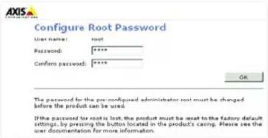
- Enter the password as set above, and click OK. If the password is lost, the AXIS 207/207W/207MW must be reset to the factory default settings. See page 15.
- If required, click Yes to install AMC (AXIS Media Control), which allows viewing of the video stream in Internet Explorer. You will need administrator rights on the computer to do this.
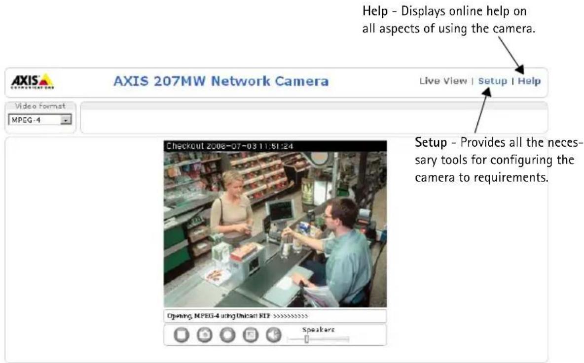
The Live View page of the AXIS 207/207W/207MW is displayed, with links to the Setup tools, which allow you to customize the camera.
6. Configure the wireless connection
Once the AXIS 207W/MW has been installed on your network, the wireless settings can be configured. These settings should always (i.e. both during installation and at all other times) be configured or changed in the camera first and in the wireless access point secondly. This ensures that the camera is always accessible when making changes.
The AXIS 207W/MW automatically senses the available network connections, and allows only one of these to be active at a time. Connecting a network cable disables the wireless connection.
Using a wired connection ensures greater secrecy while making these settings.
Open the wireless settings from Setup > System Options > Network > Wireless. These settings can also be reached from the Basic Configuration menu.
Status of Wireless Networks
This list is the result of a network scan. Access points with a disabled SSID Broadcast will not appear unless the camera is associated with it. The network currently associated to is shown in blue. A network using unsupported security is shown in grey. The following information is provided:
- SSID - The name of a wireless network (or ad-hoc device). If the same name occurs several times this means that several access points for that network were found. The AXIS 207W/MW cannot be configured to only associate with one particular access point.
Network Type - An Access Point (Master) or Ad-Hoc device. - Security - Shows which type of security the network uses. See below for the supported security types.
- Channel - Shows the wireless channel currently in use.
- Signal strength - Shows the signal strength.
- Bit rate - Shows the bit rate in Mbit/s. This can only be shown for the access point currently in use. Note that the bit rate shown is the current rate, and that this value may vary over time.
Wireless Settings
These settings control how the AXIS 207W/MW interacts with the wireless network. Apart from identifying the wireless network, it is also possible to enable wireless encryption.
SSID - This is the name of the wireless network the camera is configured for. The field accepts up to 32 alphanumeric characters. The name must be exactly the same as that used in the wireless access point, or the connection will not be established.
Leaving this field blank means the camera will attempt to access the nearest unsecured network.
Note:SSID is sometimes written as ESSID.
Network type - Setting this to Master means the camera will attempt to access the network via an access point. The Ad-hoc option allows the camera to connect to other wireless devices, e.g. a laptop with a wireless connection.
Security - The AXIS 207W/MW supports two security methods:
- WPA-PSK/WPA2-PSK (recommended method)
WEP
WPA-PSK/WPA2-PSK (Wi-Fi Protected Access - Pre-Shared Key)
The AXIS 207W/MW uses a pre-shared key (PSK) for key management. The pre-shared key can be entered either as Manual hex, as 64 hexadecimal (0-9, A-F) characters, or as a Passphrase, using 8 to 63 ASCII characters.
WEP (Wired Equivalent Protection)
WEP - Authentication - Select Open or Shared Key System Authentication, depending on the method used by your access point. Not all access points have this option, in which case they probably use Open System, which is sometimes known as SSID Authentication.
WEP - Key length - This sets the length of the key used for the wireless encryption, 64 or 128 bit. The encryption key length can sometimes be shown as 40/64 and 104/128.
WEP - Key Type - The key types available depend on the access point being used. The following options are available:
- Manual - Allows you to manually enter the hex key.
- ASCII - In this method the string must be exactly 5 characters for 64-bit WEP and 13 characters for 128-bit WEP.
- Passphrase - The passphrase can contain up to 31 characters. In 64-bit WEP, the Passphrase generates 4 different keys. For 128-bit WEP, only 1 key is generated, which is then replicated for all 4 keys. Key generation is not standardized and can differ from brand to brand. Check that the generated keys are identical to those in your access point - if not, they must be entered manually.
WEP - Active Transmit Key - When using WEP encryption, this selects which of the 4 keys the AXIS 207MW/AXIS 207W uses when transmitting.
Complete the wireless installation
- Check that the wireless settings in the camera correspond to the settings in the access point.
- Disconnect the network cable from the camera.
- Refresh the web page after 20-30 seconds to confirm the wireless connection. If the camera cannot be accessed, run AXIS IP Utility to discover the new IP address and try again.
7. Adjust the focus
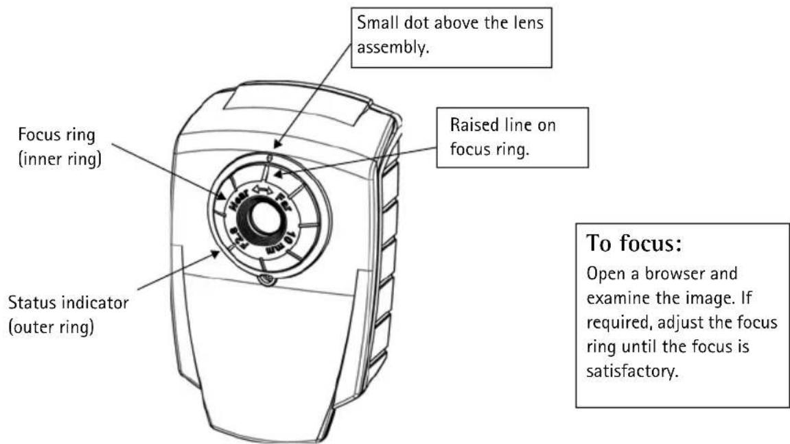
Note: Upon delivery, the raised line on the focus ring is aligned with the dot above the lens, and the focus is set to infinity.
Resetting to the Factory Default Settings
This will reset all parameters, including the IP address, to the Factory Default settings:
- Disconnect power from the camera.
- Press and hold the Control button and reconnect power.
- Keep the Control button pressed until the Status indicator displays amber (this may take up to 15 seconds), then release the button.
- When the Status indicator displays green (which can take up to 1 minute) the process is complete and the camera has been reset.
- Re-install the AXIS 207/207W/207MW using one of the methods described in this document.
It is also possible to reset parameters to the original factory default settings via the web interface. For more information, please see the online help or the user's manual.

Accessing the AXIS 207/207W/207MW from the Internet
Once installed, your AXIS 207/207W/207MW is accessible on your local network (LAN). To access the camera from the Internet, network routers must be configured to allow incoming traffic, which is usually done on a specific port. Please refer to the documentation for your router for further instructions.
For more information on this and other topics, please visit the Axis Support Web at www-axis.com/techsup
Further information
The user's manual is available from the Axis Web site at www-axis.com or from the Axis Network Video Product CD supplied with this product.
Tip!
Visit www-axis.com/techsup to check if there is updated firmware available for your AXIS 207/207W/207MW. To see the currently installed firmware version, see the Basic Configuration web page in the product's setup tools.
AXIS 207/207W/207MW Guide d'installation
WPA-PSK/WPA2-PSK (Wi-Fi Protected Access - Pre-Shared Key)
WEP (Wired Equivalent Protection)
WPA-PSK/WPA2-PSK (Wi-Fi Protected Access - Pre-Shared Key)
WEP (Wired Equivalent Protection)
WPA-PSK/WPA2-PSK (Wi-Fi Protected Access - Pre-Shared Key)
WEP (Wired Equivalent Protection)
AXIS 207: Alt. x Anch. x Prof. = 85 × 55 × 34 mm (3,3" × 2,2" × 1,3")
Copyright © Axis Communications AB, 2006
September 2006
Part No. 27192