211W - Surveillance Camera AXIS - Free user manual and instructions
Find the device manual for free 211W AXIS in PDF.

User questions about 211W AXIS
0 question about this device. Answer the ones you know or ask your own.
Ask a new question about this device
Download the instructions for your Surveillance Camera in PDF format for free! Find your manual 211W - AXIS and take your electronic device back in hand. On this page are published all the documents necessary for the use of your device. 211W by AXIS.
USER MANUAL 211W AXIS
This installation guide provides instructions for installing the AXIS 211W Network Camera on your network. For all other aspects of using the product, please see the User's Manual, available on the CD included in this package, or from www-axis.com/techsup
Installation steps
- Check the package contents against the list below.
- Hardware overview. See page 4.
- Install the hardware. See page 5.
- Set an IP address. See page 6.
- Set the password. See page 9.
- Configure the wireless connection. See page 10.
- Adjust the focus. See page 14.
Important! This product must be used in compliance with local laws and regulations.

Package contents
| Item Models/variants/notes | |
| Network camera AXIS 211W with antenna | |
| PS-K indoor power supply (country specific) | Europe UK Australia USA/Japan Argentina Korea |
| Terminal block connector | 4-pin connector block for connecting external devices to the I/O terminal connector |
| Camera stand Supplied with mounting screws | |
| CD | AXIS Network Video Product CD, including product documentation, installation tools and other software |
| Printed Materials | AXIS 211W Installation Guide (this document) Axis Warranty Document |

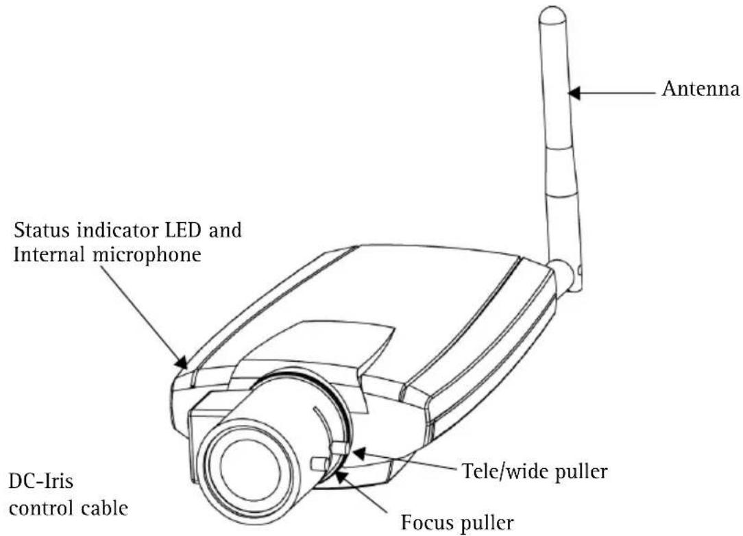
Hardware overview
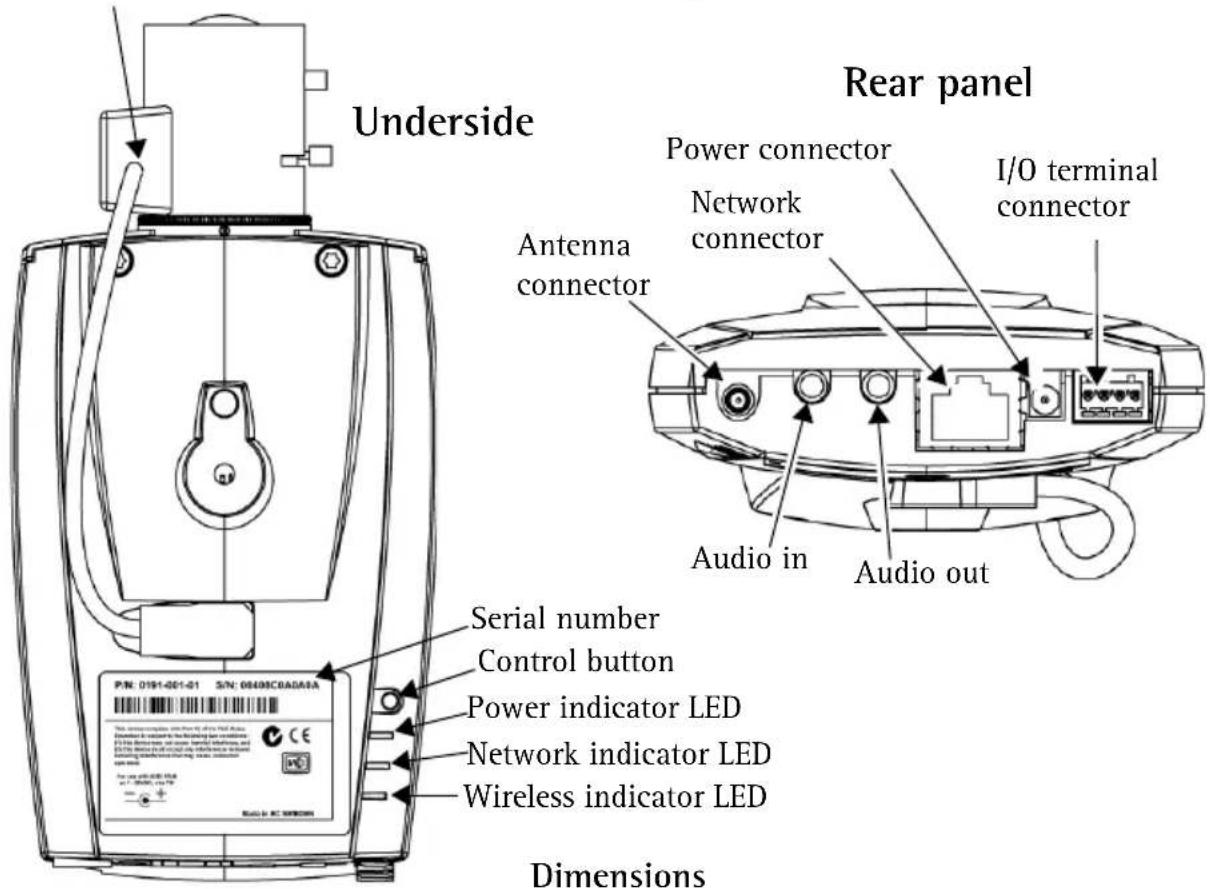
Dimensions
HxWxD = 38 x 88 x180mm (1.5" x 3.5" x 7")
Weight = 260g (0.57 lb) (without antenna)
Install the hardware
IMPORTANT! - The AXIS 211W is designed for indoor and outdoor use. To use the camera outdoors, it must be installed in an approved outdoor housing. Please see www-axis.com for more information on outdoor housings.
Connect the cables and antenna
- For indoor use, attach the antenna by screwing it into place. For outdoor use see the outdoor housing instructions.
- Connect the camera to the network using a shielded network cable. This connection is temporary and allows the camera's settings to be configured via the wired network before connecting to the wireless network.
- Optionally connect external input/output devices, e.g. alarm devices. See page 16 for information on the terminal connector pins.
- Optionally connect an active speaker and/or external microphone.
-
Connect power, using one of the methods listed below:
-
The supplied power connector.
- PoE (Power over Ethernet). If available, this is automatically detected when the network cable is connected (see above).
-
Connect power via the terminal connector. See page 16 for information on the terminal connector pins.
-
Check that the indicator LEDs indicate the correct conditions. See the table on page 17 for further details. Note that some LEDs can be disabled and may be unlit.
4 Assign an IP address
Most networks today have a DHCP server that automatically assigns IP addresses to connected devices. If your network does not have a DHCP server the AXIS 211W will use 192.168.0.90 as the default IP address.
If you would like to assign a static IP address, the recommended method in Windows is either AXIS IP Utility or AXIS Camera Management. Depending on the number of cameras you wish to install, use the method that best suits your purpose.
Both of these free applications are available on the Axis Network Video Product CD supplied with this product, or they can be downloaded from www-axis.com/techsup
| Method Recommended for Operating system | ||
| AXIS IP Utility See page 7 Single camera Small installations | Windows | |
| AXIS Camera Management See page 8 | Multiple cameras Large installations Installation on a different subnet | Windows 2000 Windows XP Pro Windows 2003 Server |
Notes:
- If assigning the IP address fails, check that there is no firewall blocking the operation.
- For other methods of assigning or discovering the IP address of the AXIS 211W, e.g. in other operating systems, see page 15.
AXIS IP Utility - single camera/small installation
AXIS IP Utility automatically discovers and displays Axis devices on your network. The application can also be used to manually assign a static IP address.
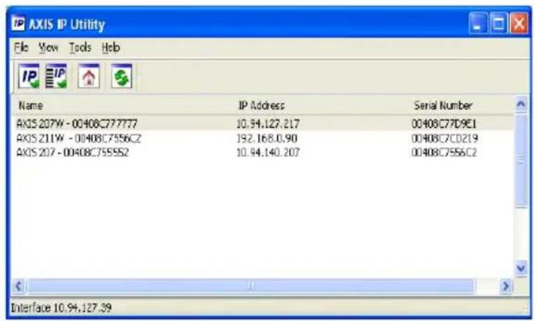
Note that the computer running AXIS IP Utility must be on the same network segment (physical subnet) as the AXIS 211W.
Automatic discovery
- Check that the AXIS 211W is connected to the network and that power has been applied.
- Start AXIS IP Utility.
- When the camera appears in the window, double-click it to open its home page.
- See page 9 for instructions on how to assign the password.
Assign the IP address manually (optional)
- Acquire an unused IP address on the same network segment as your computer.
- Select the AXIS 211W in the list.
- Click the button Assign new IP address to the selected device and enter the IP address.
- Click the Assign button and follow the instructions.
- Click the Home Page button to access the camera's web pages.
- See page 9 for instructions on how to set the password.

AXIS Camera Management - multiple cameras/large installations
AXIS Camera Management can automatically discover multiple Axis devices, show connection status, manage firmware upgrades and set IP addresses.
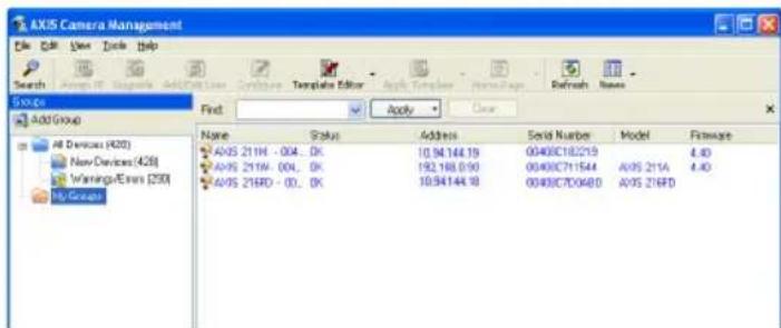
Automatic discovery
- Check that the camera is connected to the network and that power has been applied.
- Start AXIS Camera Management. When the AXIS 211W appears in the window, double-click it to open the camera's home page.
- See page 9 for instructions on how to set the password.
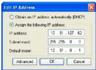
Assign an IP address in a single device
- Select AXIS 211W in AXIS Camera Management and click the Assign IP button.
- Select Assign the following IP address and enter the IP address, the subnet mask and default router the device will use.
- Click the OK button.
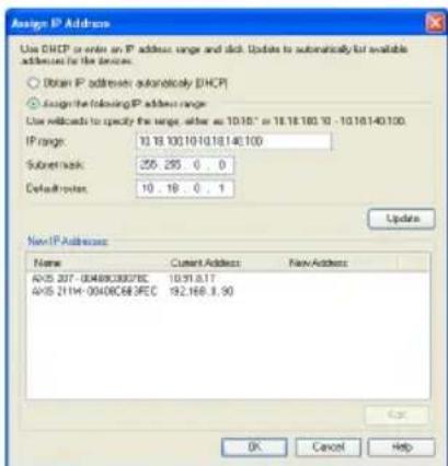
Assign IP addresses in multiple devices
AXIS Camera Management speeds up the process of assigning IP addresses to multiple devices, by suggesting IP addresses from a specified range.
- Select the devices you wish to configure (different models can be selected) and click the Assign IP button.
- Select Assign the following IP address range and enter the range of IP addresses, the subnet mask and default router the devices will use.
- Click the OK button.

Set the password
When accessing the AXIS 211W for the first time, the 'Configure Root Password' dialog will be displayed.
- Enter a password and then re-enter it, to confirm the spelling. Click OK.
- Enter the user name root in the dialog as requested.
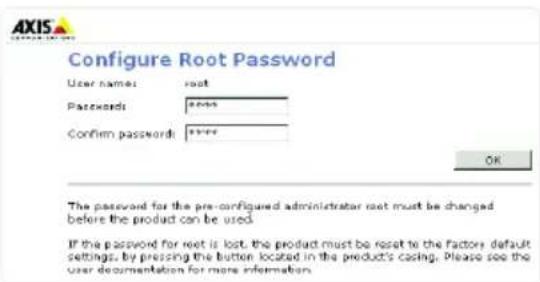
Note: The default administrator user name root cannot be deleted.
- Enter the password as set above, and click OK. If the password is lost, the AXIS 211W must be reset to the factory default settings. See page 18.
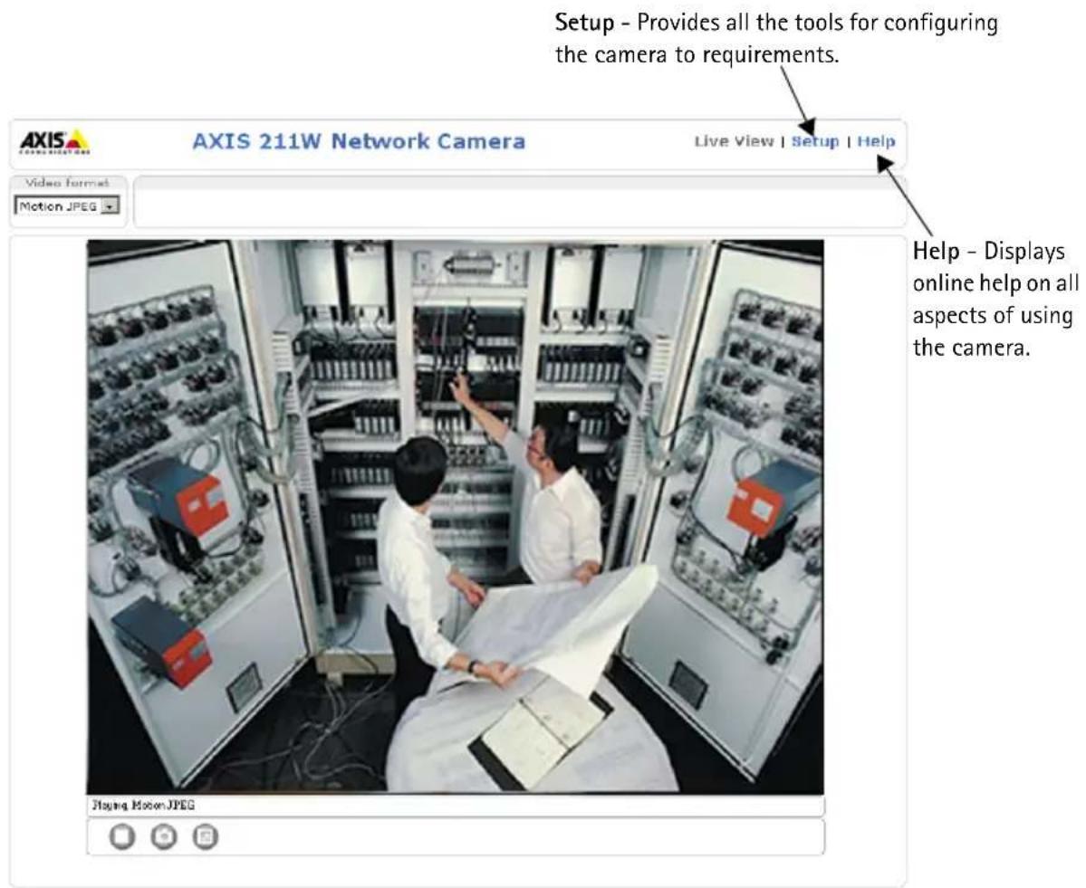
- If required, click Yes to install AMC (AXIS Media Control), which allows viewing of the video stream in Internet Explorer. You will need administrator rights on the computer to do this.
The Live View page of the AXIS 211W is displayed, with links to the Setup tools, which allow you to customize the camera.

Configure the wireless connection using a network cable
Once the AXIS 211W has been connected to your network, the wireless settings can be configured. The fastest, most secure method to configure AXIS 211W is using a wired connection, since it disables the wireless connection and ensures greater secrecy while entering settings. The AXIS 211W automatically searches for available network connections, and allows only one of these to be active at a time. Configuring the AXIS 211W using an unsecured wireless connection is not recommended, since passphrases and keys saved will be sent in plain text.
Open the wireless settings from Setup > Basic Configuration > Wireless.
Note: For even greater security use HTTPS. Go to Setup > System Options > Security > HTTPS and refer to the camera's online help.
Status of Wireless Networks
This list is the result of a network scan. Access points with a disabled SSID Broadcast will not appear unless the camera is linked to it. The network the AXIS 211W is currently linked to is shown in blue. A network using unsupported security is shown in grey. The following information is provided:
- SSID - The name of a wireless network (or ad-hoc device). If the same name occurs several times this means that several access points for that network were found. The AXIS 211W cannot be configured to be linked to only one particular access point.
Mode - An Access Point (Master) or Ad-Hoc device. - Security - Shows which type of security the network uses. See below for the supported security types.
- Channel - Shows the wireless channel currently in use.
- Signal strength - Shows the signal strength.
- Bit rate - The current bit rate in Mbit/s. This is only shown for the access point currently in use.
Wireless Settings
To establish communication, the wireless settings must be the same as in the access point or ad-hoc device. You can select a network by clicking on an access point or ad-hoc device under Status of Wireless Networks, which automatically fills in many of the required fields under Wireless Settings. Keys, passphrases and certificates that are used for security must be entered manually. Contact your Network Administrator for the requirement for the desired access point or ad-hoc device.
SSID - The name of the wireless network you are configuring the camera for. Leave this field blank if you would like the AXIS 211W to attempt to access the nearest unsecured network.
Note: SSID (Service Set Identifier) is sometimes written as ESSID (Extended Service Set Identifier).
Mode - Select Master to access the network via an access point or Ad-hoc if you would like to access another wireless device, e.g. a laptop with a wireless connection.
Security
AXIS 211W supports three security methods:
- WPA-/WPA2-PSK
WPA-/WPA2-Enterprise
WEP
Depending on the type of security chosen, the proper settings become active.
WPA-/WPA2-PSK
WPA settings - Enter the required Pre-shared Key for the access point, which can be a hexadecimal number or a passphrase
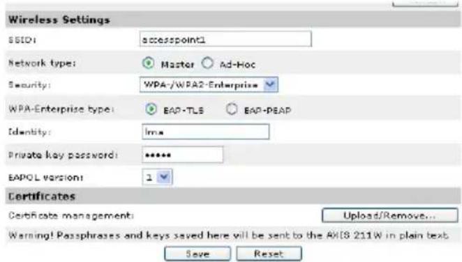
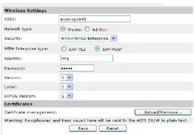
WPA-/WPA2-Enterprise
WPA- Enterprise type - Choose the type of client/server authentication being used by the access point; EAP-TLS or EAP-PEAP/MSCHAPv2.
EAP-TLS
- Identity - Enter the user identity to present to the network
- Private key password - Enter the password for your user identity
- EAPOL version - Select the version used (1 or 2) in your access point
Certificates - Upload a CA certificate to present to the access point for authentication
EAP-PEAP/MSCHAPv2
- Identity - Enter the user identity to present to the network
- Password - Enter the password to present to the network
- Version - Select the PEAP version used at the access point
- Label - Select the label used by the access point.
- EAPOL version - Select version (1 or 2) depending on the version used at the access point
Certificates - Upload a CA certificate to present to the access point for authentication
WEP
Authentication - Select Open or Shared Key System Authentication, depending on the method used by your access point. Not all access points have this option, in which case they probably use Open System, which is sometimes known as SSD Authentication.
Key length - This sets the length of the key used for the wireless encryption, 64 or 128 bit. The encryption key length can sometimes be shown as 40/64 and 104/128.
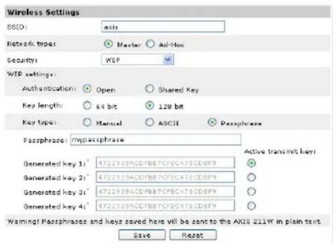
Key type - The key types available depend on the access point being used. The following options are available:
- Manual - Allows you to manually enter the hex key.
- ASCII - In this method the string must be exactly 5 characters for 64-bit WEP and 13 characters for 128-bit WEP.
- Passphrase - In 64-bit WEP, the Passphrase generates 4 different keys. For 128-bit WEP, only 1 key is generated, which is then replicated for all 4 keys. Key generation is not standardized and can differ from brand to brand. Check that the generated keys are identical to those in your access point - if not, they must be entered manually.
- WEP - Active transmit key - When using WEP encryption, this selects which of the 4 keys the AXIS 211W uses when transmitting.
Complete the wireless installation using a network cable
- Check that the wireless settings in the camera correspond to the settings in the access point.
- Disconnect the network cable from the camera.
- Refresh the web page after 20-30 seconds to confirm the wireless connection. If the camera cannot be accessed, run AXIS IP Utility to discover the camera again.
Note: Wireless settings should always (during installation and at all other times) be configured or changed in the camera first and in the wireless access point secondly. This ensures that the camera is always accessible when making changes.

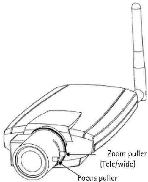
Adjust the image and focus
To focus the AXIS 211W, follow the instructions below.
- From the Basic Configuration page in the setup tools, open the Focus adjustment page.
- Set the DC-Iris to Disabled and click Save.
- Unscrew the zoom puller on the lens by turning it anti-clockwise. Adjust the zoom setting as required. Re-tighten the zoom puller.
- Unscrew the focus puller on the lens. Adjust the focus as required. Re-tighten the focus puller.
- From the Focus adjustment page, set the DC-Iris to Enabled and click Save.
Note: The DC-Iris should always be disabled while focusing the camera. This opens
the iris to its maximum, which gives the smallest depth of field and thus the best conditions for correct focusing. When the focus is set with this method it will then be maintained in any light conditions.
Accessing the AXIS 211W from the Internet
Once installed, your AXIS 211W is accessible on your local network (LAN). To access the camera from the Internet, network routers must be configured to allow incoming traffic, which is usually done on a specific port. Please refer to the documentation for your router for further instructions. For more information on this and other topics, visit the Axis Support Web at www-axis.com/techsup
Other methods of setting the IP address
The table below shows the other methods available for setting or discovering the IP address. All methods are enabled by default, and all can be disabled.
| Use in operating system | Notes | |
| UPnP™ | Windows (ME or XP) | When enabled on your computer, the camera is automatically detected and added to "My Network Places." |
| Bonjour | MAC OSX (10.4 or later) | Applicable to browsers with support for Bonjour. Navigate to the Bonjour bookmark in your browser (e.g. Safari) and click on the link to access the camera's web pages. |
| AXIS Dynamic DNS Service | All A free service from | Axis that allows you to quickly and simply install your camera. Requires an Internet connection with no HTTP proxy. See www-axiscam.net for more information. |
| ARP/Ping | All See below. The command must be issued within 2 minutes of connecting power to the camera. | |
| View DHCP server admin pages | All To view the admin | pages for the network DHCP server, see the server's own documentation. |
Set the IP address with ARP/Ping
- Acquire an IP address on the same network segment your computer is connected to.
- Locate the serial number (S/N) on the AXIS 211W label.
- Open a command prompt on your computer and enter the following commands:
| Windows syntax Windows example | |
| arp -s <IP Address><Serial Number>ping -l 408 -t <IP Address> | arp -s 192.168.0.125 00-40-8c-18-10-00 ping -l 408 -t 192.168.0.125 |
| UNIX/Linux/Mac syntax UNIX/Linux/Mac example | |
| arp -s <IP Address><Serial Number> temp ping -s 408 <IP Address> | arp -s 192.168.0.125 00:40:8c:18:10:00 temp ping -s 408 192.168.0.125 |
- Check that the network cable is connected to the camera and then start/restart the camera, by disconnecting and reconnecting power.
- Close the command prompt when you see 'Reply from 192.168.0.125: ...' or similar.
- In your browser, type in http://
in the Location/Address field and press Enter on your keyboard.
Notes:
- To open a command prompt in Windows: from the Start menu, select Run... and type cmd. Click OK.
- To use the ARP command on a Mac OS X, use the Terminal utility in Application > Utilities.
Unit connectors
Antenna connector - Reverse SMA connector for antenna.
Network connector - RJ-45 Ethernet connector. Supports Power over Ethernet. Using shielded cables is recommended.
Power connector - Mini DC connector. 7 - 20V DC, max 5W. See product label for ± connection.
Audio in - 3.5mm input for a mono microphone, or a line-in mono signal (left channel is used from a stereo signal).
Audio out - Audio output (line level) that can be connected to a public address (PA) system or an active speaker with a built-in amplifier. A pair of headphones can also be attached. A stereo connector must be used for the audio out.
I/O terminal connector - Used in applications for e.g. motion detection, event triggering, time lapse recording and alarm notifications. It provides the interface to:
- 1 transistor output - For connecting external devices such as relays and LEDs. Connected devices can be activated by AXIS VAPIX AP, output buttons on the Live View page or by an Event Type. The output will show as active (shown under Event Configuration > Port Status) if the alarm device is activated.
- 1 digital input - An alarm input for connecting devices that can toggle between an oper

Terminal connector. Note that the pins are numbered 1-4, right to left.
PIRs, door/window contacts, glass break detectors, etc. When a signal is received the state changes and the input becomes active (shown under Event Configuration > Port Status).
- Auxiliary power and GND
| Function | Pin | number | Notes | Specifications | |
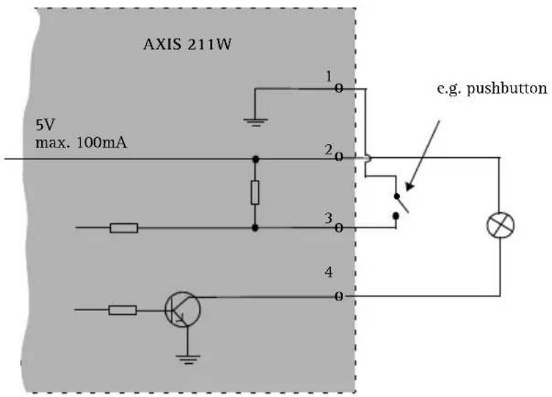
| GND 1 Ground | |||||
| 5VDC Power 2 | Can be used to power auxiliary equipment (7-20VDC) or as a +5VDC (100mA) output. | Max load = 100mA | |||
| Digital Input 3 | Connect to GND to activate, or leave floating (or unconnected) to deactivate. | Must not be exposed to voltages greater than 20VDC | |||
| Transistor Output | 4 Uses an open-collector NPN transistor with the emitter connected to the GND pin. If used with an external relay, a diode must be connected in parallel with the load, for protection against voltage transients. | Max load = 100mA Max voltage = 24VDC (to the transistor) | |||
Connection diagram
LED indicators
| LED Color | Indication | |
| Wireless Green | Green Steady for connection to a wireless network. Flashes for network activity. | |
| Red Steady for no wireless network connection. Flashes when scanning for wireless networks. | ||
| Unlit Wired mode. | ||
| Network | Green | Steady for connection to a 100 Mbit/s network. Flashes for network activity. |
| Amber | Steady for connection to 10 Mbit/s network. Flashes for network activity. | |
| Unlit No network connection. | ||
| Status Green | Steady green for normal operation. Note: The Status LED can be configured to be unlit during normal operation, or to flash only when the camera is accessed. To configure, go to Setup > System Options > LED settings. See the online help files for more information. | |
| Amber Steady during startup, during reset to factory default or when restoring settings. | ||
| Red Slow flash for failed upgrade. | ||
| Power Green | Normal operation. | |
| Amber Flashes green/amber during firmware upgrade. | ||

Resetting to the Factory Default Settings
This will reset all parameters, including the IP address, to the Factory Default settings:
- Disconnect power from the camera.
- Press and hold the Control button and reconnect power.
- Keep the Control button pressed until the Status indicator displays amber (this may take up to 15 seconds), then release the button.
- When the Status indicator displays green (which can take up to 1 minute) the process is complete and the camera has been reset.
- Re-assign the IP address, using one of the methods described in this document.
It is also possible to reset parameters to the original factory default settings via the web interface. For more information, please see the online help or the user's manual.
Further information
The user's manual is available from the Axis Web site at www-axis.com or from the Axis Network Video Product CD supplied with this product.
Tip! Visit www-axis.com/techsup to check if there is updated firmware available for your AXIS 211W. To see the currently installed firmware version, see the Basic Configuration web page in the product's Setup tools.
AXIS 211W
Copyright © Axis Communications AB, 2007
June 2007
Part No. 28248