— Mode d'emploi PDF")
Dark Power PRO 650W - Power Supply (PC) Be Quiet! - Free user manual and instructions
Find the device manual for free Dark Power PRO 650W Be Quiet! in PDF.
| Product Type | PC Power Supply |
| Brand | Be Quiet! |
| Model | Dark Power PRO 650W |
| Form Factor | ATX 12V V2.2, BTX V1.0a compatible, E-ATX |
| Rated Power | 650 W |
| Input Voltage | 100 - 240 V~, 50-60 Hz |
| Power Factor (PFC) | Active, >0.99 at full load |
| Efficiency | Up to 87% |
| Fan | 1 x 120 mm SilentWing |
| Cable Management | Modular |
| Main Connectors | 20/24-pin ATX, P4 (4-pin), EPS 8-pin (from 650W), EPS 6-pin |
| PCI Express Connectors | Up to 5 6/8-pin connectors (depending on model) |
| SATA Connectors | Up to 8 SATA connectors |
| Molex Connectors | 4 connectors (depending on cables) |
| Protections | OCP, UVP, OVP, SCP, OTP, OPP |
| 12V Rails | 4 separate rails |
| Special Features | ECASO (fan continues running after shutdown), fan speed control via motherboard |
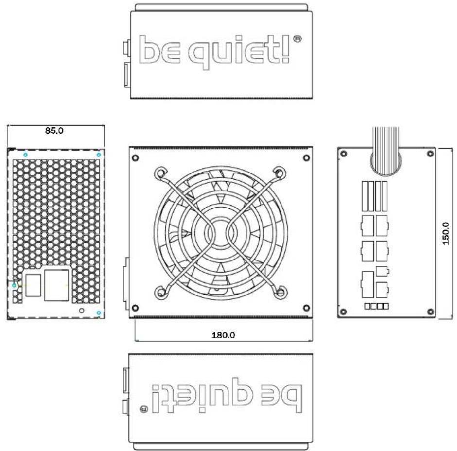
| Dimensions (L x W x H) | Approx. 150 x 86 x 160 mm (not precisely specified, standard estimate) |
| Weight | Approx. 2.5 kg (estimate for this type of unit) |
| Warranty | 3 years (including 1 year on-site replacement in metropolitan France) |
| Included Accessories | Power cord, modular cables, cable ties, screws, manual |
| Environmental Standards | RoHS and WEEE (Directive 2002/95/EC) |
| Electromagnetic Compatibility | Special anti-interference coating |
| Cleaning | Unplug, use a dry cloth, do not open |
Frequently Asked Questions - Dark Power PRO 650W Be Quiet!
User questions about Dark Power PRO 650W Be Quiet!
0 question about this device. Answer the ones you know or ask your own.
Ask a new question about this device
Download the instructions for your Power Supply (PC) in PDF format for free! Find your manual Dark Power PRO 650W - Be Quiet! and take your electronic device back in hand. On this page are published all the documents necessary for the use of your device. Dark Power PRO 650W by Be Quiet!.
USER MANUAL Dark Power PRO 650W Be Quiet!
- Introduction....22
- Warnings and safety notes 22
- Advantages and specifics .... 23 3.1 Compatibility.... 26
- Installation instructions 26
- Specifications....28
- Safeguard function....33
- Dimensions of the Power Supply.... 34
- Trouble shooting .... 34
- Accessories 36
- Article numbers & barcodes.... 36
- Notes on disposal 36
- Warranty, manufacturer specifications and copyright 37
SOMMAIRE
FRANÇAISE
Web: www.be-quiet.de
From outside of Germany: +49 40 736 76 86 559
Service E-Mail: service@be-quiet.com
line
| Loading (% of rated output power) | Efficiency (%) | | --------------------------------- | -------------- | | 0% | 70% | | 20% | 80% | | 50% | 88% | | 80% | 86% | | 100% | 83% |ÖKONOMISCH:
| Operating conditions | Environment Temperature rel. Humidity | |
| Operation | 0 ~ 40°C 20 ~ 80% | |
| Storage -25 ~ 85°C 10 ~ 90% | ||
3. LABEL
450 W
550 W
* For P4 motherboard
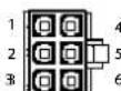
PCI EXPRESS VGA CONNECTOR
| Pin | Color | Signal | Pin | Color | Signal |
| 1 | Yellow | +12VDC | 4 | Black | COM |
| 2 | Yellow | +12VDC | 5 | Black | COM |
| 3 | Yellow | +12VDC | 6 | Black | COM |
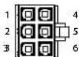
SSI WORKSTATION 6-PIN (AGP PRO)
| Pin | Color | Signal | Pin | Color | Signal |
| 1 | Orange | 3.3VDC | 4 | Black | GND |
| 2 | Orange | 3.3VDC | 5 | Black | GND |
| 3 | Yellow | +12V2 | 6 | Yellow | +12V2 |
12V splitting ( for the 450, 550 and 650W model ): =12V splitting ( for the 750, 850 and 1000W +1200W model ):
12V1 = 24pin (mainboard) = 12V1 = 24pin (mainboard))
12V2 = 4pin for CPU1 + P8 12V2 = 4pin for CPU1 + P8
12V3 = peripherals like HDD, FDD, SATA )
+ 4pin MOLEX for mainboard ( MB ) =12V4 = peripherals like HDD, FDD, SATA
12V4 = PCIe1 + PCIe2 = 12V5 = PCIe1 (6+2pin) + PCIe3 (6pin)
=12V6 = PCIe2 (6+2pin) + PCIe4 (6pin) + PCIe5
=(only for the 1000W+1200W model)
12V3 = peripherals like HDD, FDD, SATA) + 4pin MOLEX for mainboard (MB)
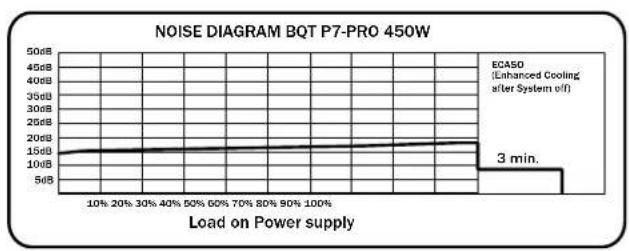
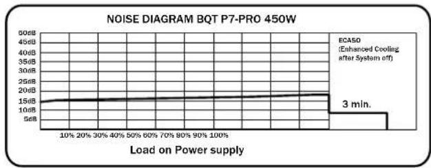
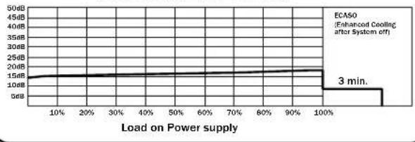
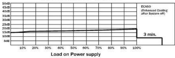
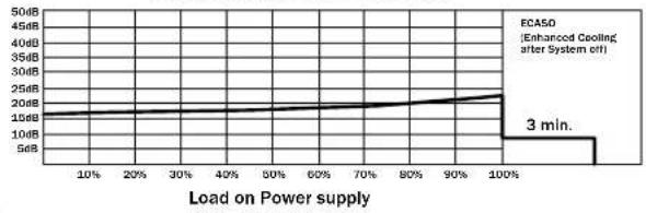
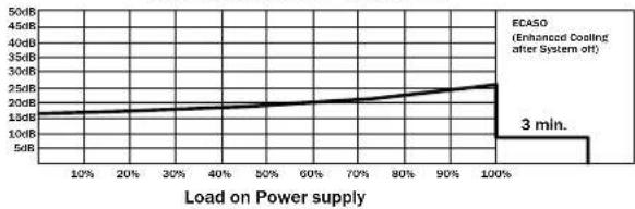
- BETRIEBSGERÄUSCHDIAGRAMME

line
| Load on Power supply | Noise Level | | --------------------- | ----------- | | 10% | 15dB | | 20% | 15dB | | 30% | 15dB | | 40% | 15dB | | 50% | 15dB | | 60% | 15dB | | 70% | 15dB | | 80% | 15dB | | 90% | 15dB | | 100% | 15dB |
line
| Load on Power supply | Noise Level (dB) | | --------------------- | ---------------- | | 10% | 1.5 | | 20% | 1.5 | | 30% | 1.5 | | 40% | 1.5 | | 50% | 1.5 | | 60% | 1.5 | | 70% | 1.5 | | 80% | 1.5 | | 90% | 1.5 | | 100% | 1.5 | | 3 min. | 3 |
line
| Load on Power supply | Noise Level (dB) | | --------------------- | ---------------- | | 10% | 15 | | 20% | 15 | | 30% | 15 | | 40% | 15 | | 50% | 15 | | 60% | 15 | | 70% | 15 | | 80% | 15 | | 90% | 15 | | 100% | 22 |
line
| Load on Power supply | Noise Level (dB) | | --------------------- | ---------------- | | 10% | 15 | | 20% | 16 | | 30% | 17 | | 40% | 18 | | 50% | 19 | | 60% | 20 | | 70% | 21 | | 80% | 22 | | 90% | 23 | | 100% | 24 |
line
| Load on Power supply | Noise Level (dB) | | ------------------- | ---------------- | | 10% | 15 | | 20% | 16 | | 30% | 17 | | 40% | 18 | | 50% | 19 | | 60% | 20 | | 70% | 21 | | 80% | 22 | | 90% | 23 | | 100% | 24 | | 3 min. | 3 |
line
| Load on Power supply | Noise Level (dB) | | --------------------- | ---------------- | | 10% | 15 | | 20% | 16 | | 30% | 17 | | 40% | 18 | | 50% | 19 | | 60% | 20 | | 70% | 21 | | 80% | 22 | | 90% | 23 | | 100% | 24 | | 3 min. | 35 |
line
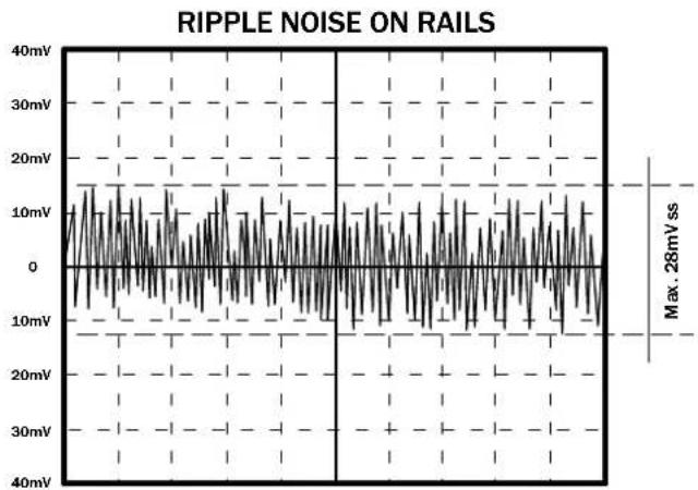
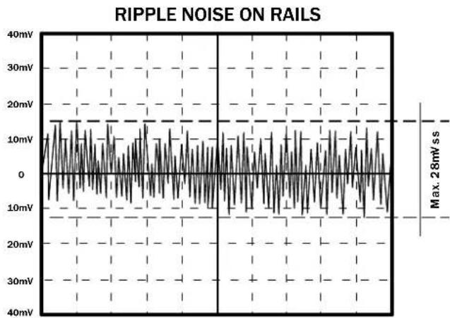
| Load on Power supply | Noise Level (dB) | | --------------------- | ---------------- | | 10% | 15 | | 20% | 16 | | 30% | 17 | | 40% | 18 | | 50% | 19 | | 60% | 20 | | 70% | 21 | | 80% | 22 | | 90% | 23 | | 100% | 24 | | 3 min. | 35 |- RIPPLE UND NOISE DIAGRAMME
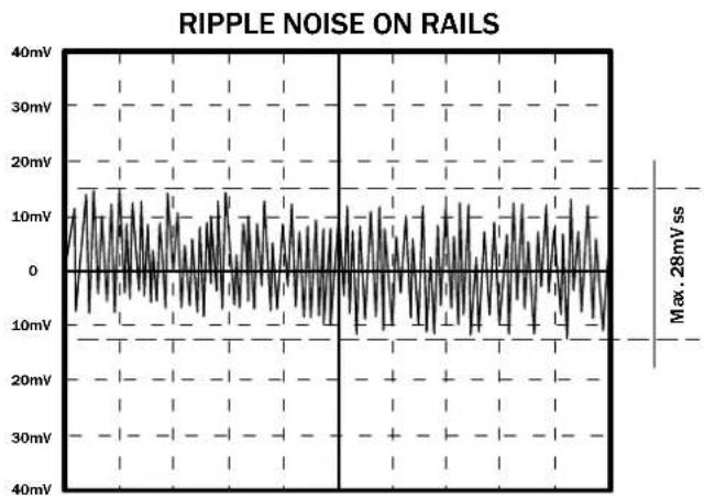
line
| Time (ms) | Voltage (mV) | | --------- | ------------ | | 0 | 0 | | Max. | 28 |text_image
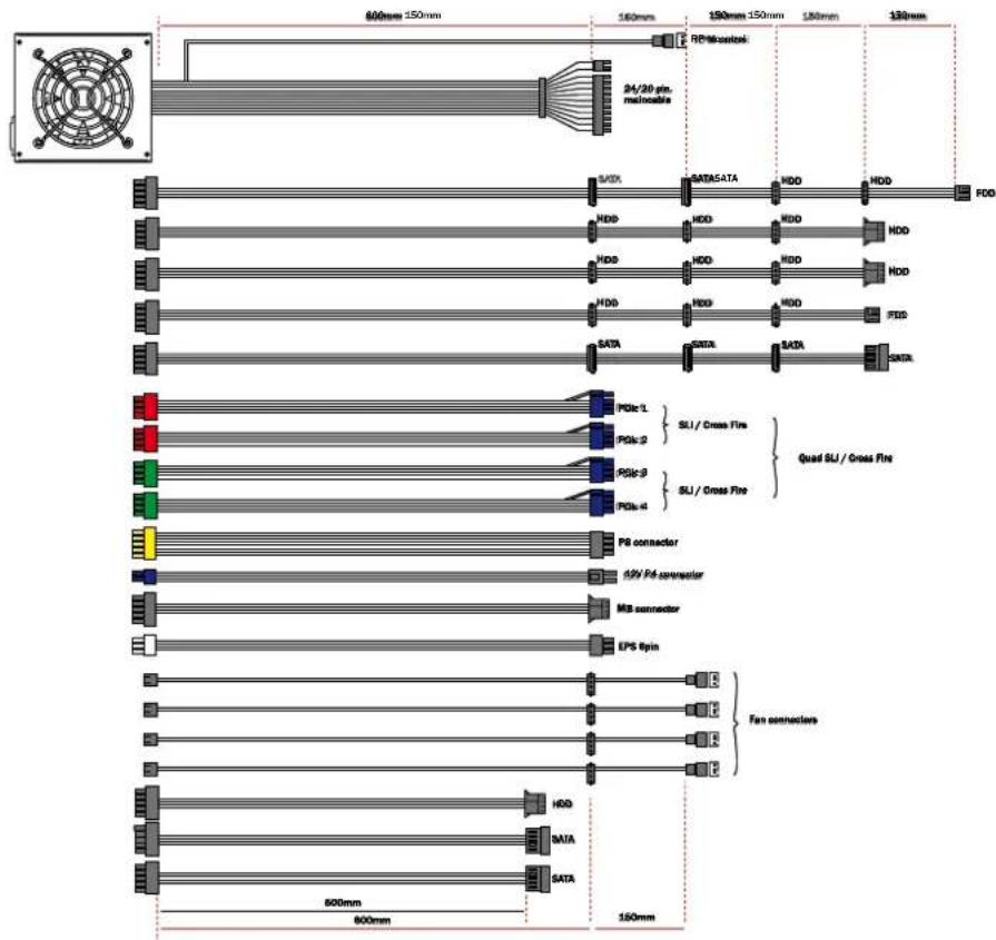
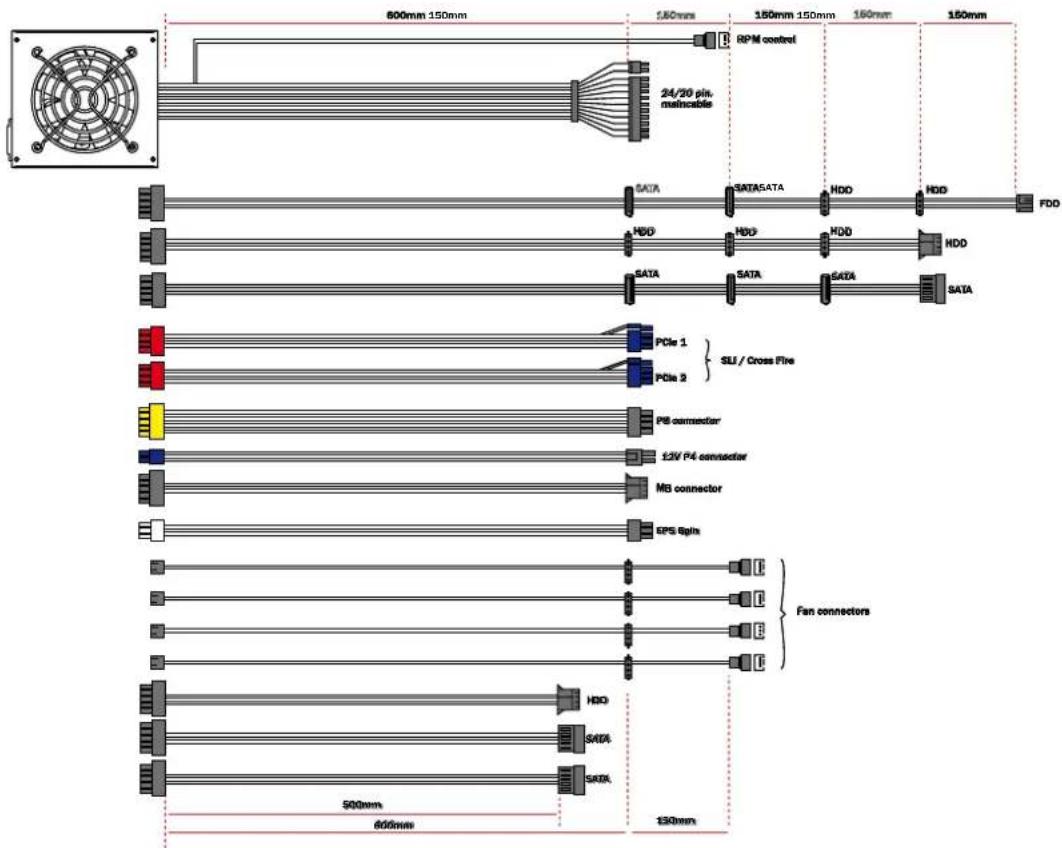
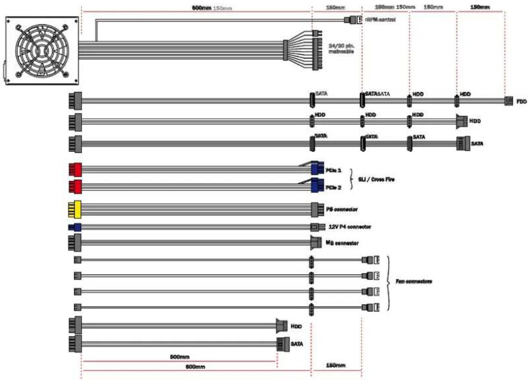
800mm 150mm 150mm 150mm 150mm 150mm RFM cantol 24/20 pin. macrable DATA HDD SATA HDD HDD HDD FDD SATA HDD HDD HDD SATA PCIe 1 PCIe 2 SLI / Cross Fire P8 connector 12V P4 connector MB connector Fan connectors HDD SATA 500mm 800mm 150mm650W

text_image
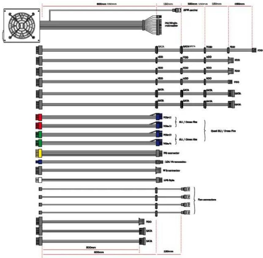
600mm 150mm 150mm 150mm 150mm 160mm 150mm 24/20 pin. mainncable RPM control DATA SATA5ATA HDD HDD FDD HDD HDD HDD HDD SATA SATA SATA SATA PCIe 1 SLI / Cross Fire PCIe 3 P8 connector 12V P4 connector MB connector EPS Spins Fan connectors HDD SADA SADA 500mm 600mm 130mm750W
text_image
600mm 150mm 160mm 150mm 150mm 140mm 130mm RP Microcontroller 24/20 pin. macrolase SATE SATA5ATA HDD HDD FDD HDD HDD HDD HDD HDD HDD HDD HDD HDD HDD HDD HDD HDD HDD HDD HDD HDD HDD HDD HDD HDD HDD HDD HDD HDD HDD HDD HDD HDD HDD HDD HDD HDD HDO SATA SATA5A SATA5A SATA5A SATA5A PDIc-1 PDIc-2 PDIc-3 PDIc-4 PDIc-1/ Cross Fire PDIc-2/ Cross Fire PDIc-3/ Cross Fire PDIc-4/ Cross Fire Quad SLI / Gross Fire P6 connector P2V P4 connector MB connector EPS Pin Fan connectors HDD SATA SATA5A SATA5A850 W

text_image
600mm 150mm 150mm 150mm 150mm 150mm 250mm 3kg/80g/n Prelimulator RPM control SACA SATA/SATA HDB HDD HDD HDD HDD HDD HDD HDD HDD HDD HDD HDD HDD FBD SATA SATA SATA SATA SARA TORC PSBv1 PU/Cross Fire PU/Bu2 PU/Bu3 PU/Bu4 PU connector 32V Monomodator M/I connector LPS-Spin Fan connectors HDD SATA SATA 800mm 600mm 150mm
text_image
800mm 150mm 100mm 180mm 150mm 180mm 180mm RP Microcontroller 24/20 pins main/able PCIe 9 SATA SATA SATA HDD HDD FDD HDD HDD HDD HDD HDD HDD HDD HDD HDD HDD FSC DATA DATA DATA DATA SATA DATA DATA DATA PCIe 4 SLI / Cross Fire PCIe 2 SLI / Cross Fire PCIe 3 PCIe 4 PS connector 12V P4 connector MB connector IPS Ipin Fan connectors NDD SATA SATA 600mm 600mm 100mmtext_image
4260052180778BN075 - BQT P7-Pro 850W

text_image
4 260052 180785BN076 - BQT P7-Pro 1000W

text_image
4 260052 180792BN077 - BQT P7-Pro 1200W

text_image
4 260052 180808text_image
RoHS 2005/95/EC12. GARANTIE, HERSTELLERANGABEN UND COPYRIGHT
21509 Glinde Germany
From outside of Germany: +49 40 736 76 86 559
Service E-Mail: service@be-quiet.com
We're happy and excited that you have decided to use a be quiet! power supply from the Dark Power PRO series in your computer. In order to be able to answer your initial questions in advance, we have summarized the advantages and specifics of the Dark Power PRO series in this comprehensive manual.
The latest generation of the Dark Power PRO series offers you many experiences and is a consequent further development of the very successful pilot production.
Should you have any questions during the initial start-up procedure, please carefully read through this instruction manual. Should you then have any additional questions, please call us at our customer service hotline:
service hotline: +49 40 736 76 86 559
E-mail: service@be-quiet.com
Website: www.be-quiet.com
PC Systems are always becoming more and more capable and require more electricity as a result of the high performance graphic cards and quicker processors, especially on the +12V cables. The power supplies provided in the Dark Power PRO series are an ideal supplement in reference to the reserve capacities, even for the operation of PCI Express graphic cards in the SLI or Crossfire networks. In addition, intelligent cable management contributes to a tidy PC and to a better air circulation when being used in space-saving Media Centre PCs or mini-format computers.
The power supplies featured in the Dark Power PRO series dispose of an extremely high rate of efficiency of up to 87%, which makes it peerless on the market. For a permanent usage intensity of your computer, the lower consumption of electricity can possibly be noticed in the next electricity bill.
2. WARNINGS AND SAFETY NOTES
Before conducting the start-up procedure, please carefully read and observe all of the points in this instruction manual. Only then can a correct operation of the power supply be ensured and as a result, you'll be able to enjoy this product for a long period of time.
Never open the cover of the power supply. The electronic components sheeted there create a high voltage that is dangerous to humans. After the separation from the network, the construction parts are often continue to harness a high voltage. As such, a power supply may only be opened by authorized personnel.
In addition, the guarantee is deemed null and void once the power supply has been opened, thus damaging the official guarantee seal.
Never operate the device with wet or moist hands.
Never place items in the openings/fanner of the power supply.
Please observe that the start-up procedure is only intended for interiors. The exterior usage can lead to heavy damages.
Do not conduct any work on the power supply when it is in a phase of line voltage. (In this situation, always place the power switch to „0“ and if necessary, pull out the power plug).
Should there be a short circuit in the device, remove the power cable and do not bring the device back into operation.
Power supplies without a universal alternating current (AC) cannot be used in the countries where, for example, there's a line voltage of 110V. The power supply can be destroyed if used with an incorrect or false AC voltage portal.
This power supply is designed for a voltage range between 100 - 240V\~ and thus, universally versatile.
Make sure that your PC is not situated directly next to a heater or another heat source because this can cause a decrease in the lifespan of all components and thus, lead to failures/casualties.
Make sure that there is a sufficient amount of ventilation in your computer case, for example, with an additional fan, because a current ATX power supply is not solely responsible for the evacuation of the complete warmth produced in the PC case.
Should you want to clean your power supply, separate it completely from the power supply system and do not use damp towels or cleaning agents. Only clean the power supply from the exterior using a dry towel.
Only start the operation of the power supply after an hour within the room air environment, because otherwise, condensation can build up in the power supply.
3. ADVANTAGES AND SPECIFICS OF YOUR NEW POWER SUPPLY
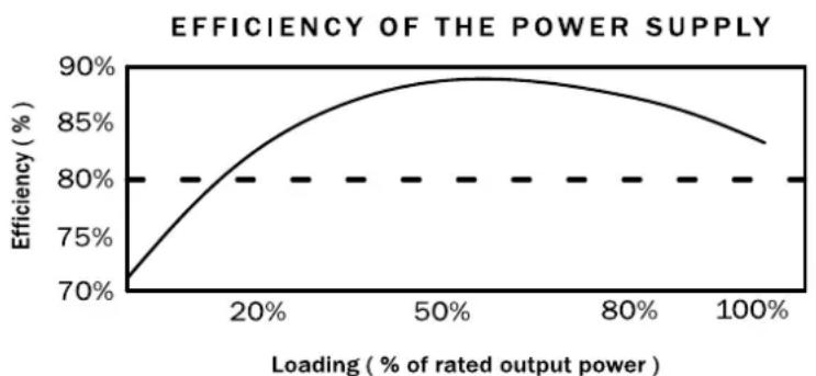
HIGH EFFICIENCY:
The power supply series from Dark Power PRO dispose of a very high degree of efficiency. This helps them to reduce the costs of electricity that accumulate within a year when there's a high rate of operation.
A high efficiency means that the power supply can convert the incoming alternative current into direct current with a lower level of losses. This leads to a lower amount of warmth loss, which then has a positive effect on cooling the power supply. Power supplies that feature as high a rate of efficiency as is exhibited by the Dark Power PRO series, can thus be operated with an extremely slow moving and thus, very quiet fan. An extremely low development of noise is the result of this continually technical advancement.
line
| Loading (% of rated output power) | Efficiency (%) | | --------------------------------- | -------------- | | 0% | 70% | | 20% | 80% | | 50% | 88% | | 80% | 86% | | 100% | 83% |ECONOMICAL:
The power supplies of the Dark Power PRO series corresponds to the current guidelines 2002/95/EG (RoHs and WEEE directives) issued by the European Union.
An environmentally conscious manner of production and the usage of materials that do not include harmful substances that are dangerous for the environment are guaranteed with be quiet! products. In this way, both we the manufacturer and you the consumer actively help in making an important contribution to the protection of our environment.
VOLTAGE STABILITY:
The power supplies from the Dark Power PRO series dispose of a first-class stability in supplying your valuable components with electricity. This is also created by the usage of high quality components. As such, output voltages are kept very close to the optimal nominal value, which is very important for a higher demand on performance.
WARMTH-DEPENDENT AIR VELOCITY CONTROL:
be quiet! power supplies from the Dark Power PRO series make use of a very precise air velocity control. This automatic control not only controls the fan in the power supply, but can also control the case fan that can be connected to the power supply. The application is rather simple: only the case fans that are usually equipped with a 3 pole and/or 4 pole connector must be connected with the respective connections onto the power supply.
The speed of the fan is regulated depending on the warmth development in the power supply. If the temperature increases, the fans automatically begin to turn faster in order to ensure a quick and effective cooling within the case. The cooling that is quickly created then contributes to the longer lifespan of its components and the power supply.
When connecting individual fans to the power supply, please ensure that these fans do not have their own thermal sensors or potentiometers.
The air velocity control disposes of an gear-up impulse. This ensures that all connected case fans are brought into gear in that a short impulse with a high level of voltage starts the fan.
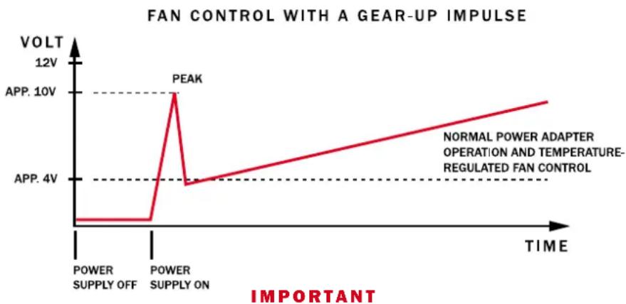
line
| TIME | VOLT | | ----------------- | ----- | | POWER SUPPLY OFF | 0V | | POWER SUPPLY ON | 12V | | APP. 4V | 4V | | APP. 10V | 10V | | NORMAL POWER ADAPTER OPERATION AND TEMPERATURE-REGULATED FAN CONTROL | 4V |Only connect one fan with every cable.
SILENT WING:
The fans built into the be quiet! Dark Power PRO are very dependable. As a result of the high efficiency of the power supply, you only require a very low amount of component cooling, which then precipitates in the special running smoothness of the fan. The 120 mm large fan is located on the underside of the power supply and ensures an optimal cooling of the components.
CONTROLLING FAN ROTATIONAL SPEED (POWER SUPPLY FANS) VIA THE MAINBOARD:
A cable on the power supply makes the connection of the power supply fan to your mainboard possible. You can read the speed indicator signal of your power supply fan via the mainboard (BIOS). The cable is to be connected to the intended slot on the mainboard and can then read the speed of the fan in the BIOS and/or operational system. Consult the manual of your mainboard as to whether this function is available.
ECASO (FAN FOLLOW-UP CONTROL):
ECASO stands for Enhanced Cooling After System Off and is to be indicated as a fan follow-up control. If the PC is turned off, all fans normally stop although it is still very warm in the interior case. With the ECASO control, this problem is solved by be quiet!. The power supply fan and all case fans attached to the power supply re-run after the system has been turned off for 3 minutes. The warmth is quickly and efficiently removed from the case after operation and does not damage its hardware.
YOUR SERVICE FOR THE NEW POWER SUPPLY:
3 YEAR WARRANTY:
With every newly purchased be quiet! Dark Power PRO power supply, you receive a three year warranty, one entire year longer than required by the law.
1 YEAR ON-SITE EXCHANGE:
Starting on the actual day of purchase, you receive the established on-site exchange service for one full year. This service will exchange your power supply with a new one on-site within for 48 hours of your call to the be quiet! hotline. (This only applies for final consumers and within Germany.)
TECHNICAL ADVANTAGES
ATX12V VERSION 2.2:
With the Dark Power PRO series, be quiet! offers a power supply that corresponds to the latest ATX 12V specifications. It offers separate 12V circuits that have an advantageous effect on the dependable function of the system. The 450, 550 and 650W models dispose of four separate 12V circuits and the 750, 850, 1000 and 1200W models dispose of six separate 12V circuits.
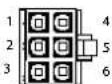
PCI EXPRESS CONNECTORS:
The power supplies from the Dark Power PRO series dispose of up to five 6 or 8 pin connectors that are necessary for the usage of PCI express graphic cards. In its basic form, every connector is a 6 pole connector that can be converted into an 8 pole connector by adding two additional pins. The 1000 and 1200W version additionally offer a fifth 6 pole connector with which the operation of a PhysX® graphic card is guaranteed.
20/24 PIN MAINBOARD CONNECTORS:
With an expandable main connector that features from 20 to 24 pins, the Dark Power PRO series is also downward compatible with all current specifications. The following standards are supported:
• ATX Specification V2.2 and older
- BTX V1.0a
• E-ATX Server mainboards with additional 8 and 6 pin connectors
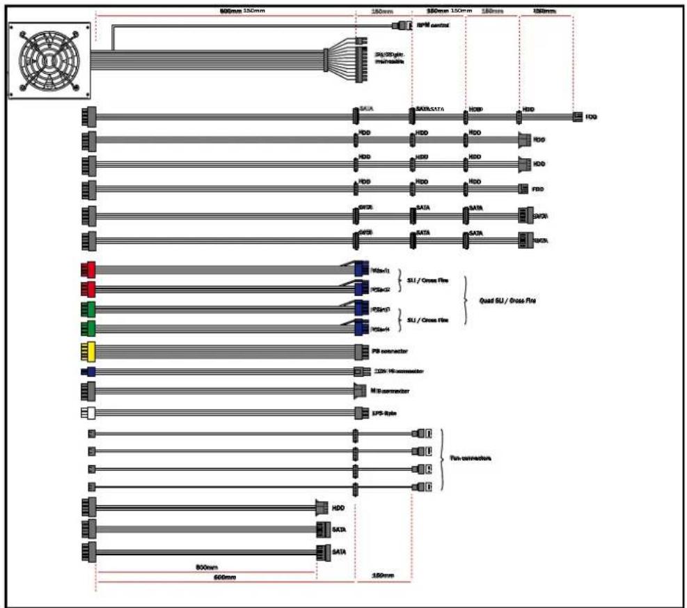
VARIABLE CABLE MANAGEMENT:
The power supply disposes of numerous, variable connection possibilities. This ensures that users can comfortably enhance their PC with many components. The various cable strands can be varied and non-used cable strands are simply stowed and do not disrupt the flow of air in the case.
EPS CONNECTORS:
With the two additional 6 pin and 8 pin connectors, the server and workstation mainboards can be respectively operated.
SERIAL ATA (SATA) CONNECTORS:
Power supplies from the Dark Power PRO series are equipped with a sufficient amount of SATA connectors. The 450 and 550W models dispose of up to 7 SATA electrical connectors, the 650 and 750W models dispose of 8 SATA electrical connectors and the 850, 1000 & 1200W models dispose of 12 SATA electrical connectors.
ELECTROMAGNETIC COMPATIBILITY (EMC):
The be quiet! power supplies featured Dark Power PRO series are compatible with current popular power supplies and mainboard specifications such as:
- Intel ATX12V Power Supply Design Guide Version 2.2 (as well as downwards compatible for V 2.01 / V 2.0 / V 1.3)
- ATX System Design Guide Version 2.2 and Version 2.1
- BTX Version 1.0a
- E-ATX Server Dual Mainboards via 8-Pin Connector
- EPS12V Version 2.91 (as of 650W)
4. INSTALLATION OF YOUR NEW POWER SUPPLY
Please read the point „Warnings and safety notes“ before you begin the installation.
Remarks: To install the power supply in your PC, you will require a screwdriver. Only use the screws delivered with the adapter because they have the provide the correct thread
You must first remove you old power supply. For this, proceed as follows:
- Separate your PC from all available sources of electricity and carefully remove all cables attached to the PC.
- Open the PC case and if necessary, observe the manufacturer instructions.
- Remove all connectors from the mainboard and all additional components such as FDD, HDD or optical drives. Please make sure that no connectors from the old power supply are connected to a component.
- Now unscrew the screws on the backside of the power supply and carefully remove them. When doing this, make sure that no cables get caught on components and thus, become damaged.
The installation of your new be quiet! Dark Power PRO power supply:
- Place the new power supply in the space provided in the case and screw it into the backside with the four screws included with the delivery. Do not use excessive force to do this.
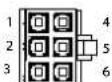
- Place the 20/24 pin into the intended connector on the mainboard. If you have a 24 pin connection, then place the remaining 4 pins in the correct position before you stick the connector in the socket. When using a 20 pin connector, fit the additional 4 pins right into the side.
- Now stick the 4 pin connector, also called the P4 connector, into the provided socket on the mainboard. This connector is will provide your CP in the future with additional electricity.
- If you have a mainboard with several processors, you will require the additional 8 pin EPS connectors (available as of 650W). You connect these into the socket on the mainboard. Some mainboards also require an additional 6 pin EPS connector. If this is the case, also connect this connector.
Remarks: Please observe the your mainboard manufacturer instructions when connecting the EPS connector. Not all mainboards dispose of these connections.
CABLE MANAGEMENT:
A specific attribute for the connection of the peripheral devices is the so-called cable management. With this cable management, you can simply remove non-used cable from or, if necessary, attach it to the power supply. With that, a cable salad is avoided and the case is kept tidy.
A special advantage is the now unchecked draft through the case. Disruptive cables prevent the air from traversing through the case, whereby the cooling is negatively influenced. This can be effectively avoided with this cable management.
Note: All cables are designed such that a mix-up of the cable directions and an interchanging of the connections is disqualified. All connectors can be easily stuck into the sockets, yet are then very tightly situated such that there is only a very low resistance. Should problems however arise, never alter the connectors and cable connections yourself. This can possibly cause permanent damage to the power supply and the other components as well as being grounds for a loss of warranty.
The allocation of the sockets on the power supply is as follows:
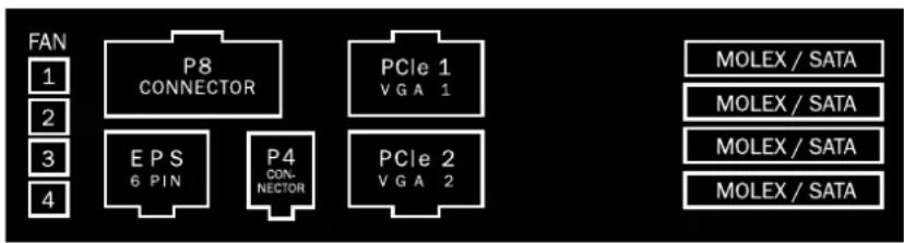
450W & 550W MODELS

flowchart
graph TD
    A["FAN"] --> B["P8 CONNECTOR"]
    B --> C["PCIe 1 VGA 1"]
    C --> D["MOLEX / SATA"]
    A --> E["P4 CONNECTOR"]
    E --> F["PCIe 2 VGA 2"]
    F --> G["MOLEX / SATA"]
650W MODEL
flowchart
graph TD
    A["FAN"] --> B["P8 CONNECTOR"]
    C["1"] --> B
    D["2"] --> B
    E["3"] --> F["EPS 6 PIN"]
    G["4"] --> H["P4 CONNECTOR"]
    I["PCIe 1 VGA 1"] --> J["MOLEX / SATA"]
    K["PCIe 2 VGA 2"] --> L["MOLEX / SATA"]
    M["PCIe 1 VGA 1"] --> N["MOLEX / SATA"]
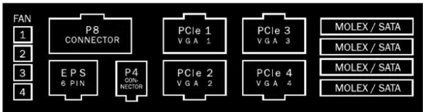
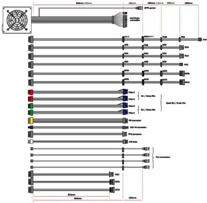
750W, 850W, 1000W & 1200W MODEL
text_image
FAN 1 2 3 4 P8 CONNECTOR EPS 6 PIN P4 CONNECTOR PCIe 1 VGA 1 PCIe 2 VGA 2 PCIe 3 VGA 3 PCIe 4 VGA 4 MOLEX / SATA MOLEX / SATA MOLEX / SATA MOLEX / SATAFAN
The four fan connections are indicated with FAN. The fan connections are to be attached at these junctions. The attached fans are later controlled by the internal automatic controls.
Attention: only one fan per connection cable!
Maximum load for all connections in sum 1.2A/14.4W!
P8 CONNECTOR
The P8 connector is required for mainboards with several processors. These provide the processors with an extra 12V circuit that is required for a stable operation.
EPS ( AS OF 650W )
The additional 6 Pin EPS connector is, for special mainboards, required in the server and workstation area. This connector is available to you as of the 650W model
MB
The connector with the MB indicator helps the additional supply of a 12V and 5V circuit for a more stable system.
PCIE1 AND PCIE2
The first two graphic card connectors are indicated in red. These serve to supply the high performance graphic cards with electricity. There is, in each case, a 6 pin connector on each end of the cable. These can then convert into 8 pin connectors by applying the pluggable pins.
PCIE3 AND PCIE4 (AB 750W)
The second two graphic card connectors are indicated in green. These also serve to supply the high performance graphic cards with electricity. There is, in each case, a 6 pin connector on each end of the cable. These can then convert into 8 pin connectors by applying the pluggable pins.
MOLEX AND SATA
The four sockets on the right side serve to connect the cable for the peripheral devices. In this case, it doesn't matter whether you use the HDD or SATA cables on the connections. You can connect this variation to each of the four sockets. There are no incompatibilities.
5. SPECIFICATIONS
1. VOLTAGE REGULATION
| Technical Data | ATX Form Factor | ATX 12V Version 2.2 | |
| AC Voltage | 100 - 240Vac | ||
| Frequency | 50 - 60Hz | ||
| PFC type | Active PFC | ||
| PF value | 0,99 @ 100% load | ||
| DC Output Regulation voltage | DC output | Tolerance | Control ranges |
| +3,3V | +/- 5% | 3,14V ~ 3,47V | |
| +5V | +/- 5% | 4,75V ~ 5,25V | |
| +12V1 | +/- 5% | 11,4V ~ 12,6V | |
| +12V2 | +/- 5% | 11,4V ~ 12,6V | |
| +12V3 | +/- 5% | 11,4V ~ 12,6V | |
| +12V4 | +/- 5% | 11,4V ~ 12,6V | |
| +12V5 | +/- 5% | 11,4V ~ 12,6V | |
| +12V6 | +/- 5% | 11,4V ~ 12,6V | |
| -12V | +/- 10% | 10,8V ~ 13,2V | |
| +5VSB | +/- 5% | 4,75V ~ 5,25V | |
2. OPERATIONAL CONDITIONS
| Operating conditions | Environment Température rel. Humidity | |
| Operation | 0~40°C 20~80% | |
| Storage -25~85°C 10~90% | ||
3. LABEL
450 W
550 W
* For P4 motherboard
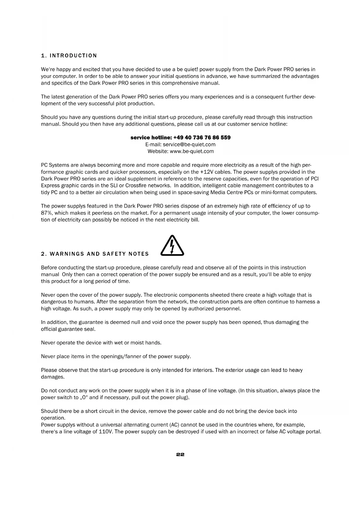
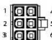
PCI EXPRESS VGA CONNECTOR
| Pin | Color | Signal | Pin | Color | Signal |
| 1 | Yellow | +12VDC | 4 | Black | COM |
| 2 | Yellow | +12VDC | 5 | Black | COM |
| 3 | Yellow | +12VDC | 6 | Black | COM |

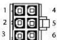
SSI WORKSTATION 6-PIN (AGP PRO)
| Pin | Color | Signal | Pin | Color | Signal |
| 1 | Orange | 3.3VDC | 4 | Black | GND |
| 2 | Orange | 3.3VDC | 5 | Black | GND |
| 3 | Yellow | +12V2 | 6 | Yellow | +12V2 |
12V splitting (for the 450, 550 and 650W model) := 12V splitting (for the 750, 850 and 1000W + 1200W model):
12V1 = 24pin (mainboard) = 12V1 = 24pin (mainboard)
12V2 = 4pin for CPU1 + P8 12V2 = 4pin for CPU1 + P8
12V3 = peripherals like HDD, FDD, SATA )
+ 4pin MOLEX for mainboard (MB) = 12V4 = peripherals like HDD, FDD, SATA
12V4 = PCIe1 + PCIe2 = 12V5 = PCIe1 (6+2pin) + PCIe3 (6pin)
=12V6 = PCIe2 (6+2pin) + PCIe4 (6pin) + PCIe5
=(only for the 1000W+1200W model)
12V3 = peripherals like HDD, FDD, SATA) + 4pin MOLEX for mainboard (MB)
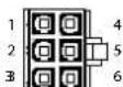
- OPERATIONS NOISE DIAGRAM
line
| Load on Power supply | Noise Level | | --------------------- | ----------- | | 10% | 12.5B | | 20% | 12.5B | | 30% | 12.5B | | 40% | 12.5B | | 50% | 12.5B | | 60% | 12.5B | | 70% | 12.5B | | 80% | 12.5B | | 90% | 12.5B | | 100% | 12.5B |
line
| Load on Power supply | Noise Level (dB) | | --------------------- | ---------------- | | 10% | 1.5 | | 20% | 1.6 | | 30% | 1.7 | | 40% | 1.8 | | 50% | 1.9 | | 60% | 2.0 | | 70% | 2.1 | | 80% | 2.2 | | 90% | 2.3 | | 100% | 2.4 | | 3 min. | 3.0 |
line
| Load on Power supply | Noise Level (dB) | | --------------------- | ---------------- | | 10% | 15 | | 20% | 16 | | 30% | 17 | | 40% | 18 | | 50% | 19 | | 60% | 20 | | 70% | 21 | | 80% | 22 | | 90% | 23 | | 100% | 24 |
line
| Load on Power supply | Noise Level (dB) | | --------------------- | ---------------- | | 10% | 15 | | 20% | 16 | | 30% | 17 | | 40% | 18 | | 50% | 19 | | 60% | 20 | | 70% | 21 | | 80% | 22 | | 90% | 23 | | 100% | 24 |
line
| Load on Power supply | Noise Level (dB) | | --------------------- | ---------------- | | 10% | 15 | | 20% | 16 | | 30% | 17 | | 40% | 18 | | 50% | 19 | | 60% | 20 | | 70% | 21 | | 80% | 22 | | 90% | 23 | | 100% | 24 | | 3 min. | 3 |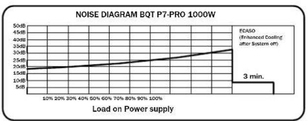
line
| Load on Power supply | Noise Level (dB) | | --------------------- | ---------------- | | 10% | 15 | | 20% | 16 | | 30% | 17 | | 40% | 18 | | 50% | 19 | | 60% | 20 | | 70% | 21 | | 80% | 22 | | 90% | 23 | | 100% | 24 | | 3 min. | 35 |
line
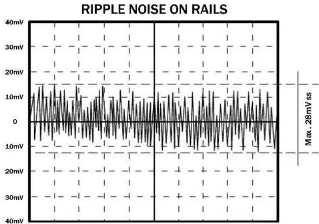
| Load on Power supply | Noise Level (dB) | | --------------------- | ---------------- | | 10% | 15 | | 20% | 16 | | 30% | 17 | | 40% | 18 | | 50% | 19 | | 60% | 20 | | 70% | 21 | | 80% | 22 | | 90% | 23 | | 100% | 24 | | 3 min. | 35 |- RIPPLE UND NOISE DIAGRAM

line
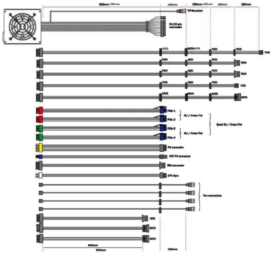
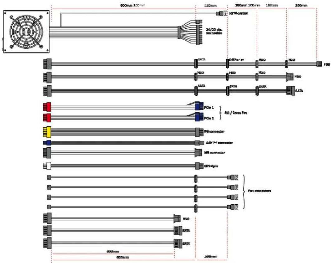
| Time (ms) | Voltage (mV) | | --------- | ------------ | | Max | 28 |7. CONNECTION OPTIONS AND CABLE LENGTHS
450W & 550W

text_image
600mm 150mm 150mm 150mm 150mm 150mm 24/20 pin. memable RFM.control SATA SATA SATA HDD HDD FDD HDD HDD HDD HDD SATA SATA SATA SATA SATA PCIe 1 } 5U / Cross Fire PCIe 2 P8 connector 12V P4 connector MB connector Fan connectors HDD SATA 500mm 600mm 150mm650W
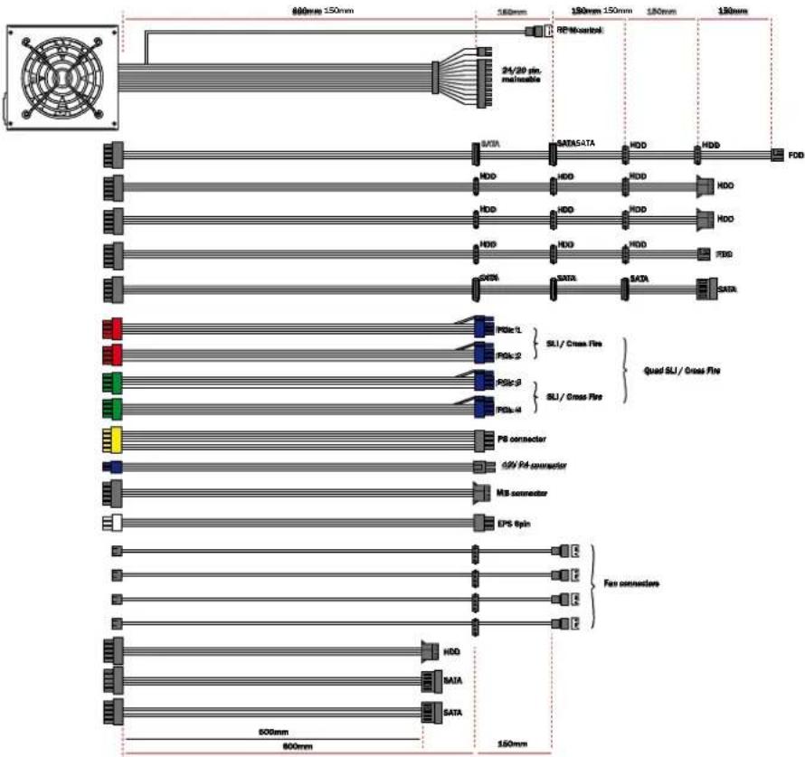
text_image
600mm 150mm 150mm 150mm 150mm 150mm 24/20 pin. maincable RPM control FDD SATA SATA5ATA HDD HDD HDD HDD HDD SATA SATA SATA SATA PCIe 1 SU / Cross Fire PCIe 2 PB connector 12V P4 connector MB connector EPS Split Fan connectors HIO SATA SATA 500mm 600mm 130mm750W

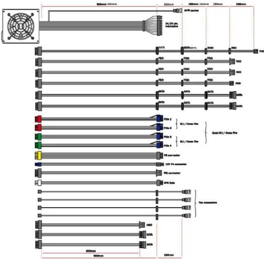
text_image
600mm 150mm 160mm 150mm 150mm 140mm 130mm RP Microcontroller 24/20 pin. macrolase SATE SATA5ATA HDD HDD FDD HDD HDD HDD HDD HDD HDD HDD HDD HDD HDD HDD HDD HDD HDD HDD HDD HDD HDD HDD HDD HDD HDD HDD HDD HDD HDD HDD HDD HDD HDD HDD HDD HDD HDO SATA SATA5A SATA5A SATA5A SATA5A PDIc-1 PDIc-2 PDIc-3 PDIc-4 PDIc-1/ Cross Fire PDIc-2/ Cross Fire PDIc-3/ Cross Fire PDIc-4/ Cross Fire Quad SLI / Gross Fire P6 connector P2V P4 connector MB connector EPS Pin Fan connectors HDD SATA SATA5A SATA5A850 W
text_image
600mm 150mm 150mm 150mm 150mm 150mm 3.9/30min Pensulator RPM control SACA SATA/SATA HDB HDD HDD HDD HDD HDD HDD HDD HDD HDD HDD HDD HDD HDD SATA SATA SATA SATA SATA SATA SATA FOS-1 SU / Cross Fire Quad SU / Cross Fire FOS-2 SU / Cross Fire FOS-3 SU / Cross Fire FOS-4 PB connector 32V Monodemeter M T-b connector SPS-Spin Fan connectors HDD SATA SATA 800mm 600mm 150mm
text_image
800mm 150mm 100mm 180mm 150mm 180mm 180mm RP Microcontroller 24/20 pin main/able PCIe 9 SACA SATA SATA HDD HDD FDD HDD HDD HDD HDD HDD HDD HDD HDD HDD HDD HDD HDD HDD FSC SATR SATR SATR SATR SATR SATR SATR PCIe 4 SLI / Cross Fire PCIe 2 SLI / Cross Fire PCIe 3 PCIe 4 PS connector 12V P4 connector MB connector IPS Ipin Fan connectors NDD SATA SATA 600mm 600mm 100mm6. SAFEGUARD FUNCTION
All be quiet! power supplies are equipped with numerous safeguard functions. They protect the user as well as the power supply and the connected components. When one of these safeguards is triggered, then a rebooting or deactivation of the system is the consequential result. Should this happen, the PC should be immediately checked for possible errors. In order to systematically detect such errors, please read the chapter „Troubleshooting“ on the following pages. The Dark Power PRO series disposes of the following safety functions:
OVER CURRENT PROTECTION
When the load on the individual circuits consists of more than the specified limit, the power supply automatically deactivates
UVP (UNDER VOLTAGE PROTECTION)
This safeguard triggers when the voltage in the circuits falls below a certain limit. In this case, the power supply is then automatically deactivated.
OVP (OVER VOLTAGE PROTECTION)
The over voltage safeguard is triggered when the voltage in the circuits is too high and the power supply deactivates.
SCP (SHORT CIRCUIT FUSE)
The safeguard during a short circuit in the secondary section of the power supply prevents a defect to the power supply and its components.
OTP (TEMPERATURE SAFEGUARD)
This safeguard is triggered when the entire performance demanded of the power supply is higher than the specified peak load. This can happen if the power supply doesn't dispose of enough performance ability.
7. DIMENSIONS OF THE POWER SUPPLY
8. TROUBLESHOOTING
please observe!
In ATX systems, the power supply receives the signal from the connected mainboard in order to be started up. For this reason, please check whether – with the help of the mainboard or the case manual – the activation/deactivation is connected correctly.
ATTENTION:
AWork with the electrical sources can lead to life-threatening injuries. In cases of trails of smoke, damaged cables and the effects of fluids, the power supply is to be immediately unplugged from its source of electricity and after that, no longer brought into operation.
Never unscrew the power supply. The are components in the interior that can contain high amounts of voltage when not used for a long period of time. Please have any and all necessary repairs be conducted by an authorized expert!
If the system for an installed power supply does not function properly, you must first check for these possible sources of error:
A. Make sure the electrical cable is plugged into both the socket and the power supply correctly and tightly. Ideally, you use a separate can only for the computer power supply.
B. Check to make sure that all connections are correctly connected to each other and correct them if necessary, for example, in the case of polarity.
C. Inspect the connection of the on and off switch from the case to the mainboard. If necessary, consult your main-board instruction manual! Switch on the power supply by placing the switch on position „I“ and activating the on/off switch on the case. If the power supply doesn't allow itself to be turned on, continue with the next point.
D. Check your system for possible short circuits or defective hardware in that you turn off your computer and separate all of the devices from the system that are not required for starting your computer. Turn the computer back on. Repeat this step and after each re-start, close one of the devices until you have found the supposed defect. If the power supply does not react due to a short circuit, wait at least 5 minutes until you re-start your computer because the device is equipped with overload protection.
FREQUENT PROBLEMS:
Problem: The selected voltages (via BIOS) are to low/high
When you check the voltage of the power supply in the BIOS of the mainboard or in the operating system, it is possible that these are displayed incorrectly. This results from the non-precise dimension of the mainboard and does not necessarily have to correspond to reality.
With a multimeter (voltage measurement device), the voltage can be determined directly from the power supply cable. This provides more precise measurement. If the circuits should still lie outside of the tolerance, please contact our customer service
Problem: After installing a new graphics card, the PC can no longer be turned on or crashes with practically every opportunity:
You have installed a new higher performance graphics card in your system and now your PC no longer starts or it seems to crash immediately with the first workload. The power supply is too weakly dimensioned for your graphics card. Before making a purchase, please take a look at our watt configurator at www.be-quiet.net. Here you'll find the right be quiet! power supply from our assortment
Important note:
Should the power supply not work, please ensure that you have thoroughly read this instruction manual and can preclude the problem causes listed here. Should the problems continue to exist, please contact our customer service immediately.
All incoming returns are checked by our RMA service. Should we determine that a power supply is indeed free of error, it will be sent back to the customer. In addition, an all-included inspection for the occurring expense is levied. The process for the on-site exchange service in the first year after the purchase is conducted as follows:
As a first step, call the be quiet! hotline for clarifying technical questions and details. A permission for the exchange will then be granted and initiated thereafter.
What we need from you in this case:
We need a copy of your purchase invoice, and a precise description of the malfunction, both of which can be sent to us per fax, e-mail or post. After this, you will receive a new power supply from us. When your new power supply is delivered to your doorstep by a DHL employee, please exchange the defective power supply to be returned to Listan. Please make sure that the power supply is packaged completely in the cardboard box, including all accessories.
9. ACCESSORIES
As part of the scope of delivery for the power supply, the following accessories are contained in addition to the cable management:
- Cooling device cable
- Operating handbook
- Wire ties
- Screws for mounting the power supply
10. ARTICLE NUMBERS AND BARCODES
BN071 - BQT P7-Pro 450W

text_image
4260052180747BN072 - BQT P7-Pro 550W

text_image
4 2 6 0 0 5 2 1 8 0 7 5 4BN073 - BQT P7-Pro 650W

text_image
4260052180761BN074 - BQT P7-Pro 750W

text_image
4260052180778BN075 - BQT P7-Pro 850W

text_image
4 2 6 0 0 5 2 1 8 0 7 8 5BN076 - BQT P7-Pro 1000W

text_image
4 2 6 0 0 5 2 1 8BN077 - BQT P7-Pro 1200W

text_image
426005218080811. NOTES ON DISPOSAL
Used electrical and electronic devices may, in accordance with European specifications*, no longer be placed in unsorted municipal solid waste. The must be collected separately. The symbol for garbage barrels on wheels implicates the necessity of the separated collection.
Please help in protecting the environment and make sure that once you've decided to no longer make use of this device, that it is placed in the systems of separate collection that are intended for it.
In Germany, you are legally** required to take an old device to such a place of separate collection instead of placing it in unsorted municipal solid waste. The responsible waste management parties (communities) subject to public law have set-up collection stations at which old device from private households in your area can be turned in free of cost. It is possible that the legal responsible waste management parties pick up the old devices themselves, even from private households.
Please read your local household refuse collection calendar or visit your city or community administration in order to inform yourself about the opportunities for turning in or collecting old devices in your area.
* Guideline 2002/96/EG of the European Parliaments and the Council from January 27th, 2003 on used electrical and electronic devices.
** Law on market introduction, withdrawal and the environmentally compatible disposal of Electrical and Electronic Equipment Act (electrical and electronic device law – The German ElektroG) from March 16th, 2005.
text_image
RoHS 2005/95/EC12. GUARANTEE, MANUFACTURER SPECIFICATIONS AND COPYRIGHT
• 3 years guarantee
Should you have any other questions on our products, please call us at our toll-free service hotline number:
+49 40 736 76 86 559
MO - FR 09:00 am - 5:30 pm
21509 Glinde, Germany
Service E-Mail: service@be-quiet.com
Copyright © Listan GmbH & Co. KG 2007. All rights reserved.
Please observe the following:
- The contents of this documentation may not – partially, in whole or copied – be passed along, propagated or saved in any form without the prior expressed written consent of Listan.
- be quiet! is a registered trademark of the company Listan GmbH & Co. KG. Other products and company names mentioned in this documentation can be the brands or trademarks of their respective owners.
- Listan continually develops its products in correspondence with its policies. Listan reserves the right to make changes and improvements to every product described in this documentation without prior announcement.
- Listan is under no circumstances responsible for the loss of data and receipts or for any special, random, direct or indirect damages, however they may arise.
- The contents of this documentation are presented as they hereby appear. Listan does not assume, expressed or implied, any guarantee for the correctness or completeness of the contents of this documentation, including, but not limited to the tacit guarantee of market suitability and the aptitude for a special purpose, unless applicable laws or jurisdiction stringently stipulate a liability. Listan retains the right to make changes to this documentation or to retract the documentation at any time without prior announcement.
1. INTRODUCTION
line
| Loading (% of rated output power) | Efficiency (%) | | --------------------------------- | -------------- | | 0% | 70% | | 20% | 80% | | 50% | 88% | | 80% | 86% | | 100% | 83% |ÉCONOMIE :
2. CONDITIONS D'EXPLOITATION
| Operating conditions | Environment Température rel. Humidity | |
| Operation | 0 ~ 40°C 20 ~ 80% | |
| Storage -25 ~ 85°C 10 ~ 90% | ||
3. ÉTIQUETTE
450 W
550 W
* For P4 motherboard
PCI EXPRESS VGA CONNECTOR
| Pin | Color | Signal | Pin | Color | Signal |
| 1 | Yellow | +12VDC | 4 | Black | COM |
| 2 | Yellow | +12VDC | 5 | Black | COM |
| 3 | Yellow | +12VDC | 6 | Black | COM |
SSI WORKSTATION 6-PIN (AGP PRO)
| Pin | Color | Signal | Pin | Color | Signal |
| 1 | Orange | 3.3VDC | 4 | Black | GND |
| 2 | Orange | 3.3VDC | 5 | Black | GND |
| 3 | Yellow | +12V2 | 6 | Yellow | +12V2 |
12V splitting (for the 450, 550 and 650W model) := 12V splitting (for the 750, 850 and 1000W + 1200W model):
12V1 = 24pin (mainboard) = 12V1 = 24pin (mainboard)
12V2 = 4pin for CPU1 + P8 12V2 = 4pin for CPU1 + P8
12V3 = peripherals like HDD, FDD, SATA )
+ 4pin MOLEX for mainboard (MB) =12V4 = peripherals like HDD, FDD, SATA
12V4 = PCIe1 + PCIe2 = 12V5 = PCIe1 (6+2pin) + PCIe3 (6pin)
=12V6 = PCIe2 (6+2pin) + PCIe4 (6pin) + PCIe5
=(only for the 1000W+1200W model)
- DIAGRAMMES ACOUSTIQUES D'EXPLOITATION
line
| Load on Power supply | Noise Level (dB) | | --------------------- | ---------------- | | 10% | 15 | | 20% | 15 | | 30% | 15 | | 40% | 15 | | 50% | 15 | | 60% | 15 | | 70% | 15 | | 80% | 15 | | 90% | 15 | | 100% | 15 |
line
| Load on Power supply | Noise Level (dB) | | --------------------- | ---------------- | | 10% | 1.5 | | 20% | 1.6 | | 30% | 1.7 | | 40% | 1.8 | | 50% | 1.9 | | 60% | 2.0 | | 70% | 2.1 | | 80% | 2.2 | | 90% | 2.3 | | 100% | 2.4 | | 3 min. | 3 |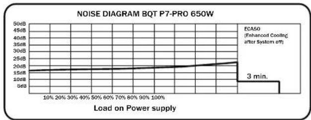
line
| Load on Power supply | Noise Level (dB) | | --------------------- | ---------------- | | 10% | 15 | | 20% | 15 | | 30% | 15 | | 40% | 15 | | 50% | 15 | | 60% | 15 | | 70% | 15 | | 80% | 15 | | 90% | 15 | | 100% | 15 | | 3 min. | 3 |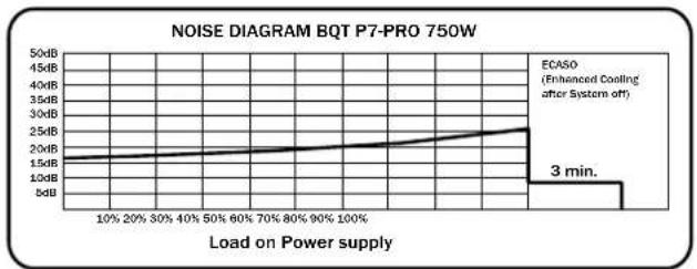
line
| Load on Power supply | Noise Level (dB) | | --------------------- | ---------------- | | 10% | 1.5 | | 20% | 1.6 | | 30% | 1.7 | | 40% | 1.8 | | 50% | 1.9 | | 60% | 2.0 | | 70% | 2.1 | | 80% | 2.2 | | 90% | 2.3 | | 100% | 2.4 | | 3 min. | 3.0 |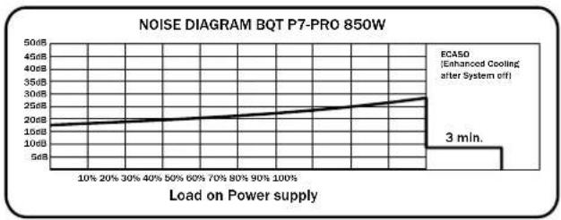
line
| Load on Power supply | Noise Level (dB) | | --------------------- | ---------------- | | 10% | 16 | | 20% | 18 | | 30% | 20 | | 40% | 22 | | 50% | 24 | | 60% | 26 | | 70% | 28 | | 80% | 30 | | 90% | 32 | | 100% | 34 |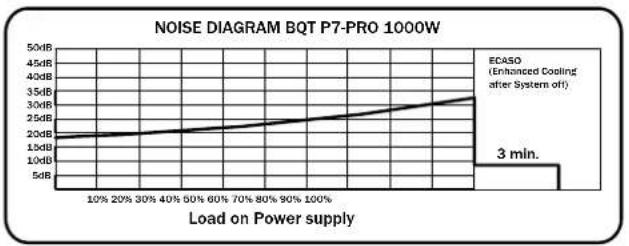
line
| Load on Power supply | Noise Level (dB) | | --------------------- | ---------------- | | 10% | 20 | | 20% | 22 | | 30% | 24 | | 40% | 26 | | 60% | 28 | | 70% | 30 | | 80% | 32 | | 90% | 34 | | 100% | 35 |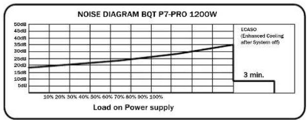
line
| Load on Power supply | Noise Level (dB) | | ------------------- | ---------------- | | 10% | 15 | | 20% | 16 | | 30% | 17 | | 40% | 18 | | 50% | 19 | | 60% | 20 | | 70% | 21 | | 80% | 22 | | 90% | 23 | | 100% | 24 | | 100% | 35 |- DIAGRAMMES D'ONDULATION ET DE NIVEAU SONORE
line
| Time (ms) | Voltage (mV) | | --------- | ------------ | | 0 | 0 | | Max. | 28 |7. POSSIBILITÉS DE CONNEXIONS ET LONGUEURS DE CÂBLES
450W & 550W

text_image
600mm 150mm 150mm 150mm 150mm 150mm 24/20 pin. memable RFM.control SATA SATA SATA HDD HDD FDD HDD HDD HDD HDD SATA SATA SATA SATA SATA PCIe 1 } 5U / Cross Fire PCIe 2 P8 connector 12V P4 connector MB connector Fan connectors HDD SATA 500mm 600mm 150mm650W

text_image
600mm 150mm 150mm 150mm 150mm 150mm 24/20 pin. maincable RPM control FDD SATA SATA5ATA HDD HDD HDD HDD HDD SATA SATA SATA SATA PCIe 1 SU / Cross Fire PCIe 2 PB connector 12V P4 connector MB connector EPS Split Fan connectors HIO SATA SATA 500mm 600mm 130mm750W
text_image
600mm 150mm 160mm 150mm 150mm 130mm 24/20 pin. macable RD® control SADC SATA5ATA HDD HDD FDD HDD HDD HDD HDD HDD HDD HDD HDD HDD HDD HDD HDD HDD HDD HDD HDD HDD HDD HDD HDD HDD HDD HDD HDD HDD HDD HDD HDD HDD HDD HDD HDD HDD HDO SATA SATAA SATA SATAA PDIc-1 PDIc-2 PDIc-3 PDIc-4 PDIc-1 / Cross Fire PDIc-2 / Cross Fire PDIc-3 / Cross Fire PDIc-4 / Cross Fire Quad SLI / Cross Fire P8 connector 10V P4 connector MS connector EPS Pin Fan connectors HDD DATA SATA SATA850 W
text_image
600mm 150mm 150mm 150mm 150mm 150mm 300mm 800mm 100mm 800mm 150mm 800mm 800mm 800mm 800mm 800mm 800mm 800mm 800mm 800mm 800mm 800mm 800mm 800mm 800mm 800mm 800mm 800mm 800mm 800mm 800mm 825mm 825mm 825mm 825mm 825mm 825mm 825mm 825mm 825mm 825mm 825mm 825mm 825mm 825mm 825mm 825mm 825mm 825mm 825mm 825mm 820mm 820mm 820mm 820mm 820mm 820mm 820mm 820mm 820mm 820mm 820mm 820mm 820mm 820mm 820mm 820mm 820mm 820mm 820mm 820mm 825mm 825mm 825mm 825mm 825mm 825mm 825mm 825mm 825mm 825mm 825mm 825mm 825mm 825mm 825mm 825mm 825mm 825mm 825mm 830mm 830mm 830mm 830mm 830mm 830mm 830mm 830mm 830mm 830mm 830mm 830mm 830mm 830mm 830mm 830mm 830mm 830mm 830mm 830mm 835m/14m/14m/14m/14m/14m/14m/14m/14m/14m/14m/14m/14m/14m/14m/14m/14m/14m/14m/14m/14m/14m/14m/14m/14m/14m/16.7.7.7.7.7.7.7.7.7.7.7.7.7.7.7.7.7.7.7.7.7.7.7.7.7.7.7.7.7.7.7.7.7.7.7.7.7.7.7.7.7.7.7.7.7.7.7.7.7.7.6.6.6.6.6.6.6.6.6.6.6.6.6.6.6.6.6.6.6.6.6.6.6.6.6.6.6.6.6.6.6.6.6.6.6.6.6.6.6.6.6.6.6.6.6.6.6.6.6.6.5. PB connector: 32kV Monodemeter: M/S connector: SPS-Spin: Fan connectors: HDD: SATA: SATA: FAN connectors: FAN connectors: FAN connectors: FAN connectors: FAN connectors: FAN connectors: FAN connectors: FAN connectors: FAN connectors: FAN connectors: FAN connectors: FAN connectors: FAN connectors: FAN connectors: FAN connectors: FAN connectors: FAN connectors: FAN connectors: FAN connectors: FAN connectors: FAN connectors: FAN connectors: FAN connectors: FAN connectors: FAN connectors: FAN connector: FAN connector: FAN connector: FAN connector: FAN connector: FAN connector: FAN connector: FAN connector: FAN connector: FAN connector: FAN connector: FAN connector: FAN connector: FAN connector: FAN connector: FAN connector: FAN connector: FAN connector: FAN connector: FAN connector: FAN connector: FAN connector: FAN connector: FAN connector: FAN connector: FAN connector: SATA: SATA: SATA: SATA: SATA: SATA: SATA: SATA: SATA: SATA: SATA: SATA: SATA: SATA: SATA: SATA: SATA: SATA: SATA: SATA: SATA: SATA: SATA: SATA: SATA: SATA: SATA: SATA: SATA: SATA: SATA: SATA: SATA: SATA : SATA : SATA : SATA : SATA : SATA : SATA : SATA : SATA : SATA : SATA : SATA : SATA : SATA : SATA : SATA : SATA : SATA : SATA : SATA : SATA : SATA : SATA : SATA : SATA : SATA : SATA : SATA : SATA : SATA : SATA : SATA : SATA : SATA : FAT : FAT : FAT : FAT : FAT : FAT : FAT : FAT : FAT : FAT : FAT : FAT : FAT : FAT : FAT : FAT : FAT : FAT : FAT : FAT : FAT : FAT : FAT : FAT : FAT : FAT : FAT : FAT : FAT : FAT : FAT : FAT : FAT : FAT : FAT / Cross Fire: FAT / Cross Fire: FAT / Cross Fire: FAT / Cross Fire: FAT / Cross Fire: FAT / Cross Fire: FAT / Cross Fire: FAT / Cross Fire: FAT / Cross Fire: FAT / Cross Fire: FAT / Cross Fire: FAT / Cross Fire: FAT / Cross Fire: FAT / Cross Fire: FAT / Cross Fire: FAT / Cross Fire: FAT / Cross Fire: FAT / C# FAT / C# FAT / C# FAT / C# FAT / C# FAT / C# FAT / C# FAT / C# FAT / C# FAT / C# FAT / C# FAT / C# FAT / C# FAT / C# FAT / C# FAT / C# FAT / C# FAT / C# FAT / C# FAT / C# FAT / C# FAT / C# FAT / C# FAT / C# FAT / C# FAT / C# FAT / C# FAT / C# FAT / C# FAT / C# FAT / C# FAT / C# FAT / C# FAT / C# FAT / C# FAT / C# FAT / C# FAT / C# FAT / C# FAT / C# FAT / C## FAT / C# FAT / C# FAT / C# FAT / C# FAT / C# FAT / C# FAT / C# FAT / C# FAT / C# FAT / C# FAT / C# FAT / C# FAT / C# FAT / C# FAT / C# FAT / C# FAT / C# FAT / C# FAT / C# FAT / C # FAT / C# FAT / C# FAT / C# FAT / C# FAT / C# FAT / C# FAT / C# FAT / C# FAT / C# FAT / C# FAT / C# FAT / C# FAT / C# FAT / C# FAT / C# FAT / C# FAT / C# FAT / C# FAT / C# FAT / C#. | | | | | | | | | | | | | | | | | | | | | | | | | | | | | | | | | | | | | | | | | | | | | | | | | | | | | | | | | | | | | | |
text_image
800mm 150mm 100mm 180mm 150mm 180mm 180mm RP Microcontroller 24/20 pins main/able PCIe 9 SATA SATA SATA HDD HDD FDD HDD HDD HDD HDD HDD HDD HDD HDD HDD HDD FSC DATA DATA DATA DATA SATA DATA DATA DATA PCIe 4 SLI / Cross Fire PCIe 2 SLI / Cross Fire PCIe 3 PCIe 4 PS connector 12V P4 connector MB connector IPS Ipin Fan connectors NDD SATA SATA 600mm 600mm 100mm6. FONCTIONS DE SÉCURITÉ
text_image
4260052180761BN074 - BQT P7-Pro 750W

text_image
4260052180778BN075 - BQT P7-Pro 850W

text_image
4 2 6 0 0 5 2 1 8 0 7 8 5BN076 - BQT P7-Pro 1000W

text_image
4 2 6 0 0 5 2 1 8BN077 - BQT P7-Pro 1200W

text_image
426005218080811. CONSIGNES POUR LA GESTION DES DÉCHETS
text_image
RoHS 2005/95/EC12. GARANTIE, FABRICANT ET COPYRIGHT
Email :service@be-quiet.com
Web: www.be-quiet.com
line
| Loading (% of rated output power) | Efficiency (%) | | --------------------------------- | -------------- | | 0% | 70% | | 20% | 80% | | 50% | 88% | | 80% | 86% | | 100% | 83% |ECONÓMICO:
| Operating conditions | Environment Temperature rel. Humidity | |
| Operation | 0 ~ 40 °C 20 ~ 80 % | |
| Storage -25 ~ 85°C 10 ~ 90% | ||
3. ETIQUETA
450 W
550 W
* For P4 motherboard

PCI EXPRESS VGA CONNECTOR
| Pin | Color | Signal | Pin | Color | Signal |
| 1 | Yellow | +12VDC | 4 | Black | COM |
| 2 | Yellow | +12VDC | 5 | Black | COM |
| 3 | Yellow | +12VDC | 6 | Black | COM |

SSI WORKSTATION 6-PIN (AGP PRO)
| Pin | Color | Signal | Pin | Color | Signal |
| 1 | Orange | 3.3VDC | 4 | Black | GND |
| 2 | Orange | 3.3VDC | 5 | Black | GND |
| 3 | Yellow | +12V2 | 6 | Yellow | +12V2 |
12V splitting (for the 450, 550 and 650W model) := 12V splitting (for the 750, 850 and 1000W + 1200W model):
12V1 = 24pin (mainboard) = 12V1 = 24pin (mainboard)
12V2 = 4pin for CPU1 + P8 12V2 = 4pin for CPU1 + P8
12V3 = peripherals like HDD, FDD, SATA )
+ 4pin MOLEX for mainboard (MB) = 12V4 = peripherals like HDD, FDD, SATA
12V4 = PCIe1 + PCIe2 = 12V5 = PCIe1 (6+2pin) + PCIe3 (6pin)
=12V6 = PCIe2 (6+2pin) + PCIe4 (6pin) + PCIe5
=(only for the 1000W+1200W model)
12V3 = peripherals like HDD, FDD, SATA) + 4pin MOLEX for mainboard (MB)
- DIAGRAMAS DE RUIDO

line
| Load on Power supply | Noise Level | | --------------------- | ----------- | | 10% | 12.5B | | 20% | 12.5B | | 30% | 12.5B | | 40% | 12.5B | | 50% | 12.5B | | 60% | 12.5B | | 70% | 12.5B | | 80% | 12.5B | | 90% | 12.5B | | 100% | 12.5B |
line
| Load on Power supply | Noise Level (dB) | | --------------------- | ---------------- | | 10% | 1.5 | | 20% | 1.5 | | 30% | 1.5 | | 40% | 1.5 | | 50% | 1.5 | | 60% | 1.5 | | 70% | 1.5 | | 80% | 1.5 | | 90% | 1.5 | | 100% | 1.5 | | 3 min. | 3 |
line
| Load on Power supply | Noise Level (dB) | | --------------------- | ---------------- | | 10% | 15 | | 20% | 15 | | 30% | 15 | | 40% | 15 | | 50% | 15 | | 60% | 15 | | 70% | 15 | | 80% | 15 | | 90% | 15 | | 100% | 22 |
line
| Load on Power supply | Noise Level (dB) | | --------------------- | ---------------- | | 10% | 15 | | 20% | 16 | | 30% | 17 | | 40% | 18 | | 50% | 19 | | 60% | 20 | | 70% | 21 | | 80% | 22 | | 90% | 23 | | 100% | 24 |
line
| Load on Power supply | Noise Level (dB) | | --------------------- | ---------------- | | 10% | 15 | | 20% | 16 | | 30% | 17 | | 40% | 18 | | 50% | 19 | | 60% | 20 | | 70% | 21 | | 80% | 22 | | 90% | 23 | | 100% | 24 |
line
| Load on Power supply | Noise Level (dB) | | --------------------- | ---------------- | | 10% | 15 | | 20% | 16 | | 30% | 17 | | 40% | 18 | | 50% | 19 | | 60% | 20 | | 70% | 21 | | 80% | 22 | | 90% | 23 | | 100% | 24 | | 3 min. | 35 |
line
| Load on Power supply | Noise Level (dB) | | --------------------- | ---------------- | | 10% | 15 | | 20% | 16 | | 30% | 17 | | 40% | 18 | | 50% | 19 | | 60% | 20 | | 70% | 21 | | 80% | 22 | | 90% | 23 | | 100% | 24 | | 3 min. | 35 |- DIAGRAMAS RIPPLE Y NOISE

line
| Time (ns) | Voltage (mV) | | --------- | ------------ | | Max. | 2.8 |text_image
600mm 150mm 150mm 150mm 150mm 150mm 24/20 pin. memable RFM.control SATA SATA SATA HDD HDD FDD HDD HDD HDD HDD SATA SATA SATA SATA SATA PCIe 1 } 5U / Cross Fire PCIe 2 P8 connector 12V P4 connector MB connector Fan connectors HDD SATA 500mm 600mm 150mm650W

text_image
600mm 150mm 150mm 150mm 150mm 150mm 24/20 pin. maincable RPM control FDD SATA SATA5ATA HDD HDD HDD HDD HDD SATA SATA SATA SATA PCIe 1 SU / Cross Fire PCIe 2 PB connector 12V P4 connector MB connector EPS Spin Fan connectors HIO SATA SATA 500mm 600mm 130mm750W

text_image
600mm 150mm 160mm 150mm 150mm 130mm RP Microcontroller 24/20 pin. macrolase SATE SATA5ATA HDD HDD FDD HDD HDD HDD HDD HDD HDD HDD SATA SATA5A SATA SATA5A PDIc-1 PDIc-2 PDIc-3 PDIc-4 P6 connector I2V P4 connector MB connector EPS Pin Fan connectors HDD SATA SATA 800mm 800mm 150mm850 W

text_image
600mm 150mm 150mm 150mm 150mm 150mm 250mm 3kg/80g/n Prelimulator RPM control SACA SATA/SATA HDB HDD HDD HDD HDD HDD HDD HDD HDD HDD HDD HDD HDD FBD SATA SATA SATA SATA SARA TORC PSBv1 PU/Cross Fire PU/Bu2 PU/Bu3 PU/Bu4 PU connector 32V Monomodator M/I connector LPS-Spin Fan connectors HDD SATA SATA 800mm 600mm 150mm
text_image
800mm 150mm 100mm 180mm 150mm 180mm 180mm RP Microcontroller 24/20 pins main/able PCIe 5 SATA SATA SATA HDD HDD FDD HDD HDD HDD HDD HDD HDD HDD HDD HDD HDD FSC DATA DATA DATA DATA SATA DATA DATA DATA PCIe 4 SLI / Cross Fire PCIe 2 SLI / Cross Fire PCIe 3 PCIe 4 PS connector 12V P4 connector MB connector BPS Ipin Fan connectors NDD SATA SATA 600mm 600mm 100mmtext_image
4260052180754BN073 - BQT P7-Pro 650W

text_image
4260052180761BN074 - BQT P7-Pro 750W

text_image
4260052180778BN075 - BQT P7-Pro 850W

text_image
4 2 6 0 0 5 2 1 8 0 7 8 5BN076 - BQT P7-Pro 1000W

text_image
4260052180792BN077 - BQT P7-Pro 1200W

text_image
4260052180808text_image
RoHS 2005/95/EC12. GARANTÍA, DATOS DEL FABRICANTE Y COPYRIGHT
21509 Glinde Germany
Web: www.be-quiet.com
line
| Loading (% of rated output power) | Efficiency (%) | | --------------------------------- | -------------- | | 0% | 70% | | 20% | 80% | | 50% | 88% | | 80% | 86% | | 100% | 83% |ECONOMICO:
| Operating conditions | Environment Température rel. Humidity | |
| Operation | 0~40°C 20~80% | |
| Storage -25~85°C 10~90% | ||
3. MARCHIO
450 W
550 W
* For P4 motherboard

PCI EXPRESS VGA CONNECTOR
| Pin | Color | Signal | Pin | Color | Signal |
| 1 | Yellow | +12VDC | 4 | Black | COM |
| 2 | Yellow | +12VDC | 5 | Black | COM |
| 3 | Yellow | +12VDC | 6 | Black | COM |
SSI WORKSTATION 6-PIN (AGP PRO)
| Pin | Color | Signal | Pin | Color | Signal |
| 1 | Orange | 3.3VDC | 4 | Black | GND |
| 2 | Orange | 3.3VDC | 5 | Black | GND |
| 3 | Yellow | +12V2 | 6 | Yellow | +12V2 |
12V splitting (for the 450, 550 and 650W model) := 12V splitting (for the 750, 850 and 1000W + 1200W model):
12V1 = 24pin (mainboard) = 12V1 = 24pin (mainboard)
12V2 = 4pin for CPU1 + P8 12V2 = 4pin for CPU1 + P8
12V3 = peripherals like HDD, FDD, SATA )
+ 4pin MOLEX for mainboard (MB) = 12V4 = peripherals like HDD, FDD, SATA
12V4 = PCIe1 + PCIe2 = 12V5 = PCIe1 (6+2pin) + PCIe3 (6pin)
=12V6 = PCIe2 (6+2pin) + PCIe4 (6pin) + PCIe5
=(only for the 1000W+1200W model)
12V3 = peripherals like HDD, FDD, SATA) + 4pin MOLEX for mainboard (MB)
line
| Load on Power supply | Noise Level | | --------------------- | ----------- | | 10% | 12.5B | | 20% | 12.5B | | 30% | 12.5B | | 40% | 12.5B | | 50% | 12.5B | | 60% | 12.5B | | 70% | 12.5B | | 80% | 12.5B | | 90% | 12.5B | | 100% | 12.5B |
line
| Load on Power supply | Noise Level (dB) | | --------------------- | ---------------- | | 10% | 1.5 | | 20% | 1.5 | | 30% | 1.5 | | 40% | 1.5 | | 50% | 1.5 | | 60% | 1.5 | | 70% | 1.5 | | 80% | 1.5 | | 90% | 1.5 | | 100% | 1.5 | | 3 min. | 3 |
line
| Load on Power supply | Noise Level (dB) | | --------------------- | ---------------- | | 10% | 15 | | 20% | 15 | | 30% | 15 | | 40% | 15 | | 50% | 15 | | 60% | 15 | | 70% | 15 | | 80% | 15 | | 90% | 15 | | 100% | 20 | | 3 min. | 22 |
line
| Load on Power supply | Noise Level (dB) | | --------------------- | ---------------- | | 10% | 15 | | 20% | 16 | | 30% | 17 | | 40% | 18 | | 50% | 19 | | 60% | 20 | | 70% | 21 | | 80% | 22 | | 90% | 23 | | 100% | 24 |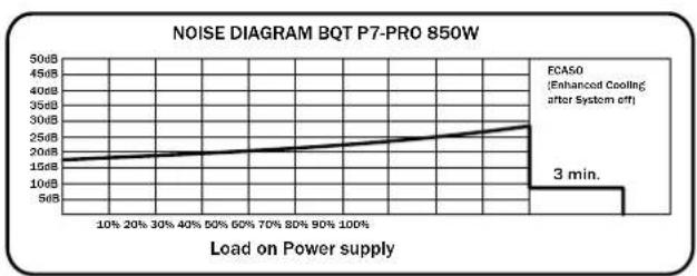
line
| Load on Power supply | Noise Level (dB) | | --------------------- | ---------------- | | 10% | 15 | | 20% | 16 | | 30% | 17 | | 40% | 18 | | 50% | 19 | | 60% | 20 | | 70% | 21 | | 80% | 22 | | 90% | 23 | | 100% | 24 | | 3 min. | 3 |
line
| Load on Power supply | Noise Level (dB) | | --------------------- | ---------------- | | 10% | 15 | | 20% | 16 | | 30% | 17 | | 40% | 18 | | 50% | 19 | | 60% | 20 | | 70% | 21 | | 80% | 22 | | 90% | 23 | | 100% | 24 | | 3 min. | 35 |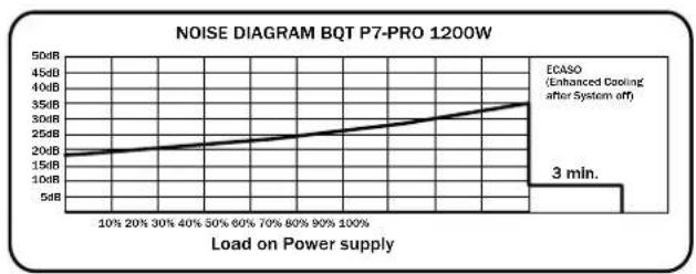
line
| Load on Power supply | Noise Level (dB) | | --------------------- | ---------------- | | 10% | 15 | | 20% | 16 | | 30% | 17 | | 40% | 18 | | 50% | 19 | | 60% | 20 | | 70% | 21 | | 80% | 22 | | 90% | 23 | | 100% | 24 | | 3 min. | 35 |- DIAGRAMMI RIPPLE E NOISE
line
| Time (ms) | Voltage (mV) | | --------- | ------------ | | Max | 28 |7. POSSIBILITÀ DI COLLEGAMENTO E LUNGHEZZE DEI CAVI
450W & 550W
text_image
600mm 150mm 150mm 150mm 150mm 150mm 24/20 pin. memable RFM.control SATA SATA SATA HDD HDD FDD HDD HDD HDD HDD SATA SATA SATA SATA SATA PCIe 1 } 5U / Cross Fire PCIe 2 P8 connector 12V P4 connector MB connector Fan connectors HDD SATA 500mm 600mm 150mm650W

text_image
600mm 150mm 150mm 150mm 150mm 150mm 24/20 pin. maincable RPM control FDD SATA SATA5ATA HDD HDD HDD HDD HDD SATA SATA SATA SATA PCIe 1 SU / Cross Fire PCIe 2 PB connector 12V P4 connector MB connector EPS Split Fan connectors HIO SATA SATA 500mm 600mm 130mm750W

text_image
600mm 150mm 160mm 150mm 150mm 140mm 130mm RP Microcontroller 24/20 pin. macrolase SATE SATA5ATA HDD HDD FDD HDD HDD HDD HDD HDD HDD HDD HDD HDD HDD HDD HDD HDD HDD HDD HDD HDD HDD HDD HDD HDD HDD HDD HDD HDD HDD HDD HDD HDD HDD HDD HDD HDD HDO SATA SATA5A SATA5A SATA5A SATA5A PDIc-1 PDIc-2 PDIc-3 PDIc-4 PDIc-1/ Cross Fire PDIc-2/ Cross Fire PDIc-3/ Cross Fire PDIc-4/ Cross Fire Quad SLI / Gross Fire P6 connector P2V P4 connector MB connector EPS Pin Fan connectors HDD SATA SATA5A SATA5A850 W

text_image
600mm 150mm 150mm 150mm 150mm 150mm 3.9/30min Pensulator RPM control SACA SATA/SATA HDB HDD HDD HDD HDD HDD HDD HDD HDD HDD HDD HDD HDD FBD SATA SATA SATA SATA SARA TORC PSBv1 SUI / Cross Fire Quad BU / Cross Fire PSBv2 SUI / Cross Fire PSBv3 PSBv4 PB connector 32V Monodemeter M/I connector SPB Split HDD Fan connectors SATA SATA 800mm 600mm 150mm
text_image
800mm 150mm 100mm 180mm 150mm 180mm 180mm RP Microcontroller 24/20 pins main/able PCIe 9 SATA SATA SATA HDD HDD FDD HDD HDD HDD HDD HDD HDD HDD HDD HDD HDD FSC DATA DATA DATA DATA SATA DATA DATA DATA PCIe 4 SLI / Cross Fire PCIe 2 SLI / Cross Fire PCIe 3 PCIe 4 PS connector 12V P4 connector MB connector IPS Ipin Fan connectors NDD SATA SATA 600mm 600mm 100mmtext_image
4260052180754BN073 - BQT P7-Pro 650W

text_image
4260052180761BN074 - BQT P7-Pro 750W

text_image
4260052180778BN075 - BQT P7-Pro 850W

text_image
4 2 6 0 0 5 2 1 8 0 7 8 5BN076 - BQT P7-Pro 1000W

text_image
4260052180792BN077 - BQT P7-Pro 1200W

text_image
426005218080811. INDICAZIONI PER LO SMALTIMENTO
text_image
RoHS 2005/95/EC12. GARANZIA, DATI DEL PRODUTTORE E COPYRIGHT
line
| Loading (% of rated output power) | Efficiency (%) | | ---------------------------------- | -------------- | | 0% | 70% | | 20% | 80% | | 50% | 88% | | 80% | 86% | | 100% | 83% |EKONOMICZNIE:
| Operating conditions | Environment Temperature rel. Humidity | |
| Operation | 0 ~ 40°C 20 ~ 80% | |
| Storage -25 ~ 85°C 10 ~ 90% | ||
3. ETYKIETA
450 W
550 W
* For P4 motherboard

PCI EXPRESS VGA CONNECTOR
| Pin | Color | Signal | Pin | Color | Signal |
| 1 | Yellow | +12VDC | 4 | Black | COM |
| 2 | Yellow | +12VDC | 5 | Black | COM |
| 3 | Yellow | +12VDC | 6 | Black | COM |
SSI WORKSTATION 6-PIN (AGP PRO)
| Pin | Color | Signal | Pin | Color | Signal |
| 1 | Orange | 3.3VDC | 4 | Black | GND |
| 2 | Orange | 3.3VDC | 5 | Black | GND |
| 3 | Yellow | +12V2 | 6 | Yellow | +12V2 |
12V splitting (for the 450, 550 and 650W model) := 12V splitting (for the 750, 850 and 1000W + 1200W model):
12V1 = 24pin (mainboard) = 12V1 = 24pin (mainboard)
12V2 = 4pin for CPU1 + P8 12V2 = 4pin for CPU1 + P8
12V3 = peripherals like HDD, FDD, SATA )
+ 4pin MOLEX for mainboard (MB) =12V4 = peripherals like HDD, FDD, SATA
12V4 = PCIe1 + PCIe2 = 12V5 = PCIe1 (6+2pin) + PCIe3 (6pin)
=12V6 = PCIe2 (6+2pin) + PCIe4 (6pin) + PCIe5
=(only for the 1000W+1200W model)
12V3 = peripherals like HDD, FDD, SATA) + 4pin MOLEX for mainboard (MB)
- DIAGRAMY POZIOMU HAŁASU W TRAKCIE PRACY

line
| Load on Power supply | Noise Level | | --------------------- | ----------- | | 10% | 15dB | | 20% | 15dB | | 30% | 15dB | | 40% | 15dB | | 50% | 15dB | | 60% | 15dB | | 70% | 15dB | | 80% | 15dB | | 90% | 15dB | | 100% | 15dB |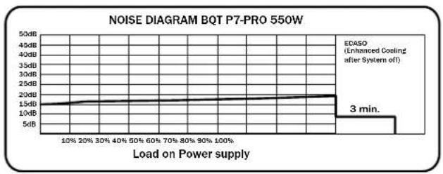
line
| Load on Power supply | Noise Level (dB) | | --------------------- | ---------------- | | 10% | 1.5 | | 20% | 1.5 | | 30% | 1.5 | | 40% | 1.5 | | 50% | 1.5 | | 60% | 1.5 | | 70% | 1.5 | | 80% | 1.5 | | 90% | 1.5 | | 100% | 1.5 | | 3 min. | 3 |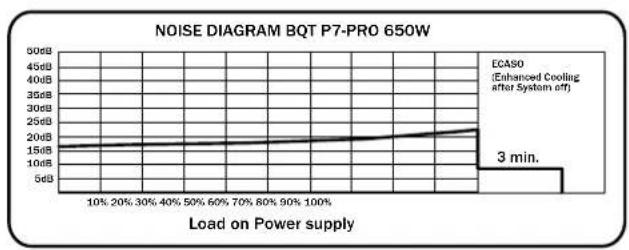
line
| Load on Power supply | Noise Level (dB) | | --------------------- | ---------------- | | 10% | 15 | | 20% | 16 | | 30% | 17 | | 40% | 18 | | 50% | 19 | | 60% | 20 | | 70% | 21 | | 80% | 22 | | 90% | 23 | | 100% | 24 |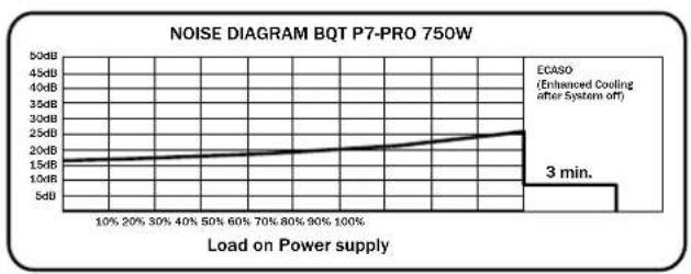
line
| Load on Power supply | Noise Level (dB) | | --------------------- | ---------------- | | 10% | 15 | | 20% | 16 | | 30% | 17 | | 40% | 18 | | 50% | 19 | | 60% | 20 | | 70% | 21 | | 80% | 22 | | 90% | 23 | | 100% | 24 |
line
| Load on Power supply | Noise Level (dB) | | --------------------- | ---------------- | | 10% | 15 | | 20% | 16 | | 30% | 17 | | 40% | 18 | | 50% | 19 | | 60% | 20 | | 70% | 21 | | 80% | 22 | | 90% | 23 | | 100% | 24 |
line
| Load on Power supply | Noise Level (dB) | | --------------------- | ---------------- | | 10% | 15 | | 20% | 16 | | 30% | 17 | | 40% | 18 | | 50% | 19 | | 60% | 20 | | 70% | 21 | | 80% | 22 | | 90% | 23 | | 100% | 24 | | 3 min. | 35 |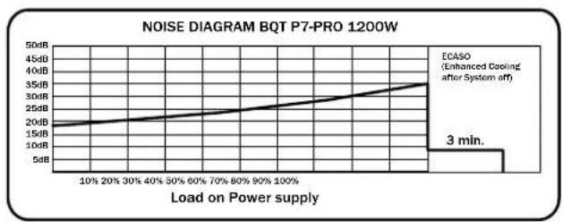
line
| Load on Power supply | Noise Level (dB) | | --------------------- | ---------------- | | 10% | 15 | | 20% | 16 | | 30% | 17 | | 40% | 18 | | 50% | 19 | | 60% | 20 | | 70% | 21 | | 80% | 22 | | 90% | 23 | | 100% | 24 | | 3 min. | 35 |- DIAGRAMY RIPPLE I NOISE

line
| Time (ms) | Voltage (mV) | | --------- | ------------ | | 0 | 0 | | Max. | 28 |7. MOŻLIWOŚCI PODŁĄCZENIA I DŁUGOŚCI KABLI
450W & 550W

text_image
800mm 150mm 150mm 150mm 150mm 150mm 24/20 pin. memable RFM.control SATA SATA/SATA HDD HDD FDD HDD HDD HDD HDD SATA SATA SATA SATA PCIe 1 } SLJ / Cross Fire PCIe 2 P8 connector 12V P4 connector MB connector Fan connectors HDD SATA 500mm 600mm 150mm650W

text_image
600mm 150mm 150mm 150mm 150mm 150mm 24/20 pin. maincable RPM control FDD SATA SATA5ATA HDD HDD HDD HDD HDD SATA SATA SATA SATA PCIe 1 SU / Cross Fire PCIe 2 PB connector 12V P4 connector MB connector EPS Spin Fan connectors HDD SATA SATA 500mm 600mm 130mm750W

text_image
600mm 150mm 160mm 150mm 150mm 140mm 130mm RP Microcontroller 24/20 pin. macrolase SATE SATA5ATA HDD HDD FDD HDD HDD HDD HDD HDD HDD HDD HDD HDD HDD HDD HDD HDD HDD HDD HDD HDD HDD HDD HDD HDD HDD HDD HDD HDD HDD HDD HDD HDD HDD HDD HDD HDD HDO SATA SATA5A SATA5A SATA5A SATA5A PDIc-1 PDIc-2 PDIc-3 PDIc-4 PDIc-1/ Cross Fire PDIc-2/ Cross Fire PDIc-3/ Cross Fire PDIc-4/ Cross Fire Quad SLI / Gross Fire P6 connector P2V P4 connector MB connector EPS Pin Fan connectors HDD SATA SATA5A SATA5A850 W
text_image
800mm 150mm 350mm 380mm 150mm 180mm 1200mm SIP/36 pole multistable RPM control SATA SATA/SATA HDBP HDD HDD HDD HDD HDD HDD HDD HDD HDD HDD HDD HDD HDD HDD HDD HDD HDD HDD HDD HDD HDD HDD HDD HDD HDD HDD HDD HDD HDD HDD HDD HDD HDD HDD
text_image
800mm 150mm 100mm 180mm 150mm 180mm 180mm RP Microcontroller 24/20 pin main/able PCIe 9 SACA SATA SATA HDD HDD FDD HDD HDD HDD HDD HDD HDD HDD HDD HDD HDD HDD HDD HDD FSC SATR SATR SATR SATR SATR SATR SATR PCIe 4 SLI / Cross Fire PCIe 2 SLI / Cross Fire PCIe 3 PCIe 4 PS connector 12V P4 connector MB connector BPS Ipin Fan connectors NDD SATA SATA 600mm 600mm 100mm6. FUNKCJE BEZPIECZEŃSTWA
text_image
4260052180754BN073 - BQT P7-Pro 650W

text_image
4260052180761BN074 - BQT P7-Pro 750W

text_image
4260052180778BN075 - BQT P7-Pro 850W

text_image
4 2 6 0 0 5 2 1 8 0 7 8 5BN076 - BQT P7-Pro 1000W

text_image
4 2 6 0 0 5 2 1 8BN077 - BQT P7-Pro 1200W

text_image
426005218080811. WSKAZÓWKI DOTYCZĄCE RECYCLINGU
text_image
RoHS 2005/95/EC12. GWARANCJA, INFORMACJE DOTYCZĄCE PRODUCENTA ORAZ PRAWA AUTORSKIE
Listan Poland sp. z o.o.
Połczyńska 65
01-361 Warszawa
Polska
Spoza Polski: +48 022 664 80 22
Service E-Mail: info@be-quiet.pl
line
| Loading (% of rated output power) | Efficiency (%) | | --------------------------------- | -------------- | | 0% | 70% | | 20% | 80% | | 50% | 88% | | 80% | 86% | | 100% | 83% || Operating conditions | Environment Temperature rel. Humidity | |
| Operation | 0 ~ 40 °C 20 ~ 80 % | |
| Storage -25 ~ 85°C 10 ~ 90% | ||
3. ОБОЗНАЧЕНИЕ
450 W
550 W
12V splitting (for the 450, 550 and 650W model) := 12V splitting (for the 750, 850 and 1000W + 1200W model):
12V1 = 24pin (mainboard) = 12V1 = 24pin (mainboard)
12V2 = 4pin for CPU1 + P8 12V2 = 4pin for CPU1 + P8
12V3 = peripherals like HDD, FDD, SATA)
+ 4pin MOLEX for mainboard (MB) =12V4 = peripherals like HDD, FDD, SATA
12V4 = PCIe1 + PCIe2 = 12V5 = PCIe1 (6+2pin) + PCIe3 (6pin)
=12V6 = PCIe2 (6+2pin) + PCIe4 (6pin) + PCIe5
=(only for the 1000W+1200W model)
5. ГРАФИК РАБОЧИХ ПОМЕХ
NOISE DIAGRAM BQT P7-PRO 450W
line
| Load on Power supply | Power Supply | | --------------------- | ------------ | | 10% | 15dB | | 20% | 15dB | | 30% | 15dB | | 40% | 15dB | | 50% | 15dB | | 60% | 15dB | | 70% | 15dB | | 80% | 15dB | | 90% | 15dB | | 100% | 3dB |NOISE DIAGRAM BQT P7-PRO 550W
line
| Load on Power supply | Power Supply | | --------------------- | ------------ | | 10% | 15dB | | 100% | 3dB |NOISE DIAGRAM BQT P7-PRO 650W
line
| Load on Power supply | Power Output (dB) | | --------------------- | ----------------- | | 10% | 156 | | 20% | 160 | | 30% | 164 | | 40% | 168 | | 50% | 172 | | 60% | 176 | | 70% | 180 | | 80% | 184 | | 90% | 188 | | 100% | 204 |NOISE DIAGRAM BQT P7-PRO 750W
line
| Load on Power supply | Power Output (dB) | | --------------------- | ----------------- | | 10% | 15 | | 20% | 16 | | 30% | 17 | | 40% | 18 | | 50% | 19 | | 60% | 20 | | 70% | 21 | | 80% | 22 | | 90% | 23 | | 100% | 24 |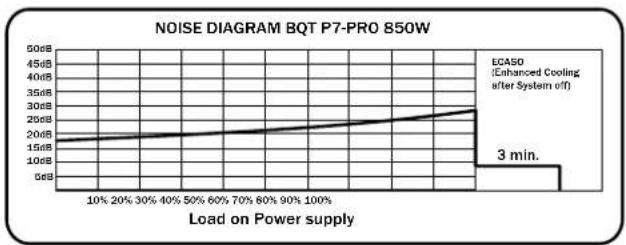
line
| Load on Power supply | Noise Level (dB) | | ------------------- | ---------------- | | 10% | 15 | | 20% | 16 | | 30% | 17 | | 40% | 18 | | 50% | 19 | | 60% | 20 | | 70% | 21 | | 80% | 22 | | 90% | 23 | | 100% | 24 | | 3 min. | 3 |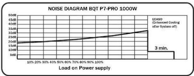
line
| Load on Power supply | Noise Level (dB) | | ------------------- | ---------------- | | 10% | 15 | | 20% | 16 | | 30% | 17 | | 40% | 18 | | 50% | 19 | | 60% | 20 | | 70% | 21 | | 80% | 22 | | 90% | 23 | | 100% | 24 | | 3 min. | 32 |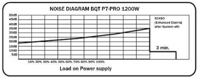
line
| Load on Power supply | Noise Level (dB) | | --------------------- | ---------------- | | 10% | 15 | | 20% | 18 | | 30% | 20 | | 40% | 22 | | 50% | 24 | | 60% | 26 | | 70% | 28 | | 80% | 30 | | 90% | 32 | | 100% | 35 |6. ДИАГРАММЫ ПУЛЬСАЦИИ И ШУМОВ
line
| Time (ms) | Voltage (mV) | | --------- | ------------ | | 0 | 0 | | 10 | ~5 | | 20 | ~10 | | 30 | ~5 | | 40 | 0 |text_image
800mm 150mm 150mm 150mm 150mm 150mm 34/20 pin. mableable HDD SATA SATASATA HDD HDD FDD HDD SATA SATASATA HDD HDD SATA PCIe 1 SU / Cross Fire PCIe 2 P6 connector 12V P4 connector Mia connector Fan connectors HDD SATA 500mm 800mm 150mm650W
text_image
500mm 150mm 24/20 pu. main/mable 500mm 500mm 150mm 150mm 150mm RPM control HDD HDD HDD FDD SATA SATA/SATA HDD HDD HDD HDD SATA SATA SATA PCIe 1 PCIe 2 3L1/Cross Fire P8 connector 12V P4 connector MB connector GPS 6pin Fan connectors HDD SATA SATA750W
text_image
800mm 150mm 160mm 190mm 150mm 180mm 190mm RD Monitor 24/20 pin. multivariable SATA SATA5ATA HDD HDD FOD HDD HDD HDD HDD HDD HDD HDD HDD HDD HDD HDD HDD HDD HDD HDD HDD HDD HDD HDD HDD HDD HDD HDD HDD HDD HDD HDD HDD HDD HDD HDD HDD HDD HDD L PDLc-1 PDLc-2 PDLc-3 PDLa-4 PDLb-5 PDLb-6 PDLb-7 PDLb-8 PDLb-9 PDLb-10 PDLb-11 PDLb-12 PDLb-13 PDLb-14 PDLb-15 PDLb-16 PDLb-17 PDLb-18 PDLb-19 PDLb-20 PDLb-21 PDLb-22 PDLb-23 PDLb-24 PDLb-25 PDLb-26 PDLb-27 PDLb-28 PDLb-29 PDLb-30 PDLb-31 PDLb-32 PDLb-33 PDLb-34 PDLb-35 PDLb-36 PDLb-37 PDLb-38 PDLb-39 PDLb-40 PDLb-41 PDLb-42 PDLb-43 PDLb-44 PDLb-45 PDLb-46 PDLb-47 PDLb-48 PDLb-49 PDLb-50 PDLb-51 PDLb-52 PDLb-53 PDLb-54 PDLb-55 PDLb-56 PDLb-57 PDLb-58 PDLb-59 PDLb-60 PDLb-61 PDLb-62 PDLb-63 PDLb-64 PDLb-65 PDLb-66 PDLb-67 PDLb-68 PDLb-69 PDLb-70 PDLb-71 PDLb-72 PDLb-73 PDLb-74 PDLb-75 PDLb-76 PDLb-77 PDLb-78 PDLb-79 PDLb-80 PDLb-81 PDLb-82 PDLb-83 PDLb-84 PDLb-85 PDLb-86 PDLb-87 PDLb-88 PDLb-89 PDLb-90 PDLb-91 PDLb-92 PDLb-93 PDLb-94 PDLb-95 PDLb-96 PDLb-97 PDLb-98 PDLb-99 PDLb-100850 W
text_image
800mm 150mm 500mm 300mm 150mm 500mm 24/30 phs. malineable RPM control SATA SATA/SATA HDD HDD FDD FDD HDD HDD HDD HDD HDD HDD HDD SATA SATA SATA SATA SATA PDI 5 PDI 2 PDI 2 PDI 4 PB connector 12V P4 connector NB connector EPS Sple Pan connectors HDD SATA SATA 600mm 900mm 150mm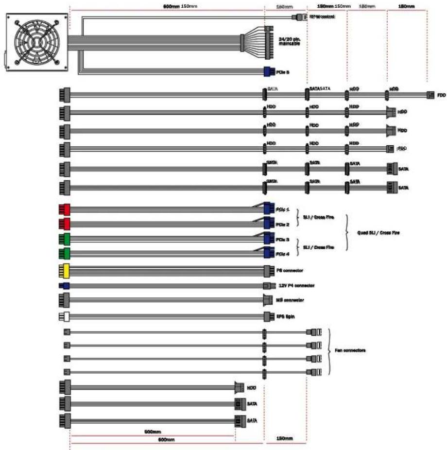
text_image
600mm 150mm 180mm 180mm 150mm 180mm 180mm 24/20 pin. mainable PCIe 5 SAC HDD HDD HDD HDD HDD HDD HDD HDD HDD HDD HDD HDD HDD HDD HDD HDD HDD HDD HDD HDD HDD HDD HDD HDD HDD HDD HDD HDD HDD HDD HDD HDD HDD HDD 1 PCIe 2 PCIe 3 PCIe 4 PCIe 4 PCIe 4 PCIe 4 PCIe 4 PCIe 4 PCIe 4 PCIe 4 PCIe 4 PCIe 4 PCIe 4 PCIe 4 PCIe 4 PCIe 4 PCIe 4 PCIe 4 PCIe 4 PCIe 4 PCIe 4 PCIe 4 PCIe 1 SLI / Cross Fire SLI / Cross Fire Quad SLI / Cross Fire PU connector 12V PU connector MB encoder BPS Ipin Fan connectorstext_image
4260052180754BN073 - BQT P7-Pro 650W

text_image
4 2 6 0 0 5 2 1 8BN074 - BQT P7-Pro 750W

text_image
4260052180778BN075 - BQT P7-Pro 850W

text_image
4260052180785BN076 - BQT P7-Pro 1000W

text_image
4 2 6 0 0 5 2 1 8BN077 - BQT P7-Pro 1200W