
Z87 Extreme3 - Motherboard ASROCK - Free user manual and instructions
Find the device manual for free Z87 Extreme3 ASROCK in PDF.

| Product Type | Motherboard |
| Brand and Model | ASRock Z87 Extreme3 |
| Socket and Chipset | Socket LGA1150, Intel Z87 Chipset |
| Compatible Processors | Intel Core i7/i5/i3/Xeon/Pentium/Celeron (4th Generation) |
| Supported Memory Type | DDR3 DIMM, up to 2933+ MHz (OC), 4 slots, max 32 GB |
| Expansion Slots | 2 x PCI Express 3.0 x16, 2 x PCI Express 2.0 x16, 2 x PCI |
| Storage Connectors | 6 x SATA 3 (6 Gb/s), RAID 0/1/5/10 support |
| USB Connectors | 4 x USB 3.0 (rear), 2 x USB 2.0 (rear), headers for 4 additional USB 2.0 and 2 additional USB 3.0 |
| Video Outputs | DVI-D, HDMI (max 4096x2304 @ 24 Hz), VGA |
| Audio | Realtek ALC892, 7.1-channel HD Audio |
| Network | Gigabit Ethernet (Realtek RTL8111E), 802.3az support |
| Required Power | ATX 24-pin and ATX 12V 8-pin connectors |
| Dimensions (Form Factor) | ATX (~30.5 x 24.4 cm) |
| Estimated Weight | Approximately 1.2 kg |
| Special Features | CrossFireX support, advanced overclocking, UEFI BIOS, Intel Rapid Storage Technology |
| Maintenance and Cleaning | Dust regularly with a soft dry cloth. Avoid moisture. |
| Safety | Overvoltage protection (solid capacitors). Handle with anti-static precautions. |
| Spare Parts and Repairability | Repair by a professional recommended. Spare parts available on ASRock website. |
| Warranty | Standard manufacturer's warranty (consult ASRock) |
Frequently Asked Questions - Z87 Extreme3 ASROCK
User questions about Z87 Extreme3 ASROCK
0 question about this device. Answer the ones you know or ask your own.
Ask a new question about this device
Download the instructions for your Motherboard in PDF format for free! Find your manual Z87 Extreme3 - ASROCK and take your electronic device back in hand. On this page are published all the documents necessary for the use of your device. Z87 Extreme3 by ASROCK.
USER MANUAL Z87 Extreme3 ASROCK
Published April 2013
Copyright©2013 ASRock INC. All rights reserved.
Copyright Notice:
No part of this documentation may be reproduced, transcribed, transmitted, or translated in any language, in any form or by any means, except duplication of documentation by the purchaser for backup purpose, without written consent of ASRock Inc.
Products and corporate names appearing in this documentation may or may not be registered trademarks or copyrights of their respective companies, and are used only for identification or explanation and to the owners' benefit, without intent to infringe.
Disclaimer:
Specifications and information contained in this documentation are furnished for informational use only and subject to change without notice, and should not be constructed as a commitment by ASRock. ASRock assumes no responsibility for any errors or omissions that may appear in this documentation.
With respect to the contents of this documentation, ASRock does not provide warranty of any kind, either expressed or implied, including but not limited to the implied warranties or conditions of merchantability or fitness for a particular purpose.
In no event shall ASRock, its directors, officers, employees, or agents be liable for any indirect, special, incidental, or consequential damages (including damages for loss of profits, loss of business, loss of data, interruption of business and the like), even if ASRock has been advised of the possibility of such damages arising from any defect or error in the documentation or product.
The terms HDMI and HDMI High-Definition Multimedia Interface, and the HDMI logo are trademarks or registered trademarks of HDMI Licensing LLC in the United States and other countries.

This device complies with Part 15 of the FCC Rules. Operation is subject to the following two conditions:
(1) this device may not cause harmful interference, and
(2) this device must accept any interference received, including interference that may cause undesired operation.
CALIFORNIA, USA ONLY
The Lithium battery adopted on this motherboard contains Perchlorate, a toxic substance controlled in Perchlorate Best Management Practices (BMP) regulations passed by the California Legislature. When you discard the Lithium battery in California, USA, please follow the related regulations in advance.
"Perchlorate Material-special handling may apply, see www.dtsc.ca.gov/hazardouswaste/perchlorate"
ASRock Website: http://www.asrock.com

AUSTRALIA ONLY
Our goods come with guarantees that cannot be excluded under the Australian Consumer Law. You are entitled to a replacement or refund for a major failure and compensation for any other reasonably foreseeable loss or damage caused by our goods. You are also entitled to have the goods repaired or replaced if the goods fail to be of acceptable quality and the failure does not amount to a major failure. If you require assistance please call ASRock Tel: +886-2-28965588 ext.123 (Standard International call charges apply)
The terms HDMI and HDMI High-Definition Multimedia Interface, and the HDMI logo are trademarks or registered trademarks of HDMI Licensing LLC in the United States and other countries.

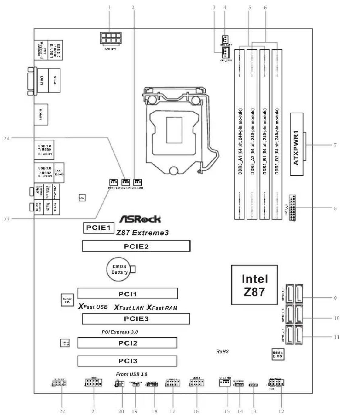
Motherboard Layout
No. Description
1 ATX 12V Power Connector (ATX12V1)
2 Chassis Fan Connector (CHA_FAN2)
3 CPU Fan Connector (CPU_FAN1)
4 CPU Fan Connector (CPU_FAN2)
5 2 x 240-pin DDR3 DIMM Slots (DDR3_A1, DDR3_B1)
6 2 x 240-pin DDR3 DIMM Slots (DDR3_A2, DDR3_B2)
7 ATX Power Connector (ATXPWR1)
8 USB 3.0 Header (USB3_4_5)
9 SATA3 Connectors (SATA3_0_1)
10 SATA3 Connectors (SATA3_2_3)
11 SATA3 Connectors (SATA3_4_5)
12 System Panel Header (PANEL1)
13 Power LED Header (PLED1)
14 Clear CMOS Jumper (CLRCMOS1)
15 Chassis Fan Connector (CHA_FAN1)
16 USB 2.0 Header (USB2_3)
17 USB 2.0 Header (USB4_5)
18 Chassis Speaker Header (SPEAKER1)
19 SPDIF Out Connector (SPDIF_OUT1)
20 Infrared Module Header (IR1)
21 COM Port Header (COM1)
22 Front Panel Audio Header (HD_AUDIO1)
23 Power Fan Connector (PWR_FAN1)
24 Chassis Fan Connector (CHA_FAN3)
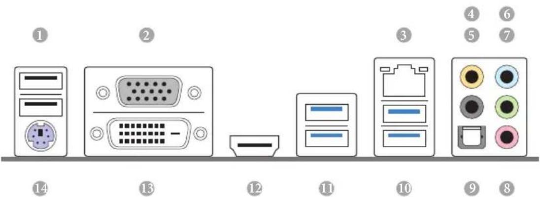
I/O Panel
No. Description No. Description
1 USB 2.0 Ports (USB01) 8 Microphone (Pink)
2 VGA Port 9 Optical SPDIF Out Port
3 LAN RJ-45 Port 10 USB 3.0 Ports (USB3_23)
4 Central / Bass (Orange) 11 USB 3.0 Ports (USB3_01)
5 Rear Speaker (Black) 12 HDMI Port
6 Line In (Light Blue) 13 DVI-D Port
7 Front Speaker (Lime)* 14 PS/2 Keyboard Port
- There are two LEDs on each LAN port. Please refer to the table below for the LAN port LED indications.
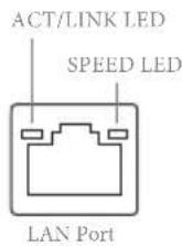
| Activity / Link LED Speed LED | |||
| Status Description Status Description | |||
| Off No Link Off | 10Mbps connection | ||
| Blinking | Data Activity | Orange | 100Mbps connection |
| On Link Green | Gbps connection | ||
** If you use a 2-channel speaker, please connect the speaker's plug into "Front Speaker Jack". See the table below for connection details in accordance with the type of speaker you use.
| Audio Output Channels | Front Speaker (No. 7) | Rear Speaker (No. 5) | Central / Bass (No. 4) | Line In (No. 6) |
| 2 V -- -- | ||||
| 4 V V -- -- | ||||
| 6 V V V -- | ||||
| 8 V V V V |

To enable Multi-Streaming, you need to connect a front panel audio cable to the front panel audio header. After restarting your computer, you will find the "Mixer" tool on your system. Please select "Mixer ToolBox", click "Enable playback multi-streaming", and click "ok". Choose "2CH", "4CH", "6CH", or "8CH" and then you are allowed to select "Realtek HDA Primary output" to use the Rear Speaker, Central/Bass, and Front Speaker, or select "Realtek HDA Audio 2nd output" to use the front panel audio.
*** The eSATA connector supports SATA with cables within 1 meters.
Chapter 1 Introduction
Thank you for purchasing ASRock Z87 Extreme3 motherboard, a reliable motherboard produced under ASRock's consistently stringent quality control. It delivers excellent performance with robust design conforming to ASRock's commitment to quality and endurance.
In this manual, Chapter 1 and 2 contains the introduction of the motherboard and step-by-step installation guides. Chapter 3 contains the operation guide of the software and utilities. Chapter 4 contains the configuration guide of the BIOS setup.

Because the motherboard specifications and the BIOS software might be updated, the content of this documentation will be subject to change without notice. In case any modifications of this documentation occur, the updated version will be available on ASRock's website without further notice. If you require technical support related to this motherboard, please visit our website for specific information about the model you are using. You may find the latest VGA cards and CPU support list on ASRock's website as well. ASRock website http://www.asrock.com.
1.1 Package Contents
1.2 Specifications
Platform
quality Conductive Polymer Capacitors)
A-Style
CPU
Pentium® / Celeron® in LGA1150 Package
Turbo Boost 2.0 Technology
* K-Series unlocked CPU
Chipset
Z87
Memory
1866(OC)/1600/1333/1066 non-ECC, un-buffered memory
(see CAUTION)
Extreme Memory Profile (XMP)1.3/1.2
Expansion
Slot
(PCIE2); dual at x8 (PCIE2) / x8 (PCIE3))
TM and CrossFireX TM
TM and SLI^TM
Graphics
be supported only with processors which are GPU integrated.
Sync Video with AVC, MVC (S3D) and MPEG-2 Full HW Encode1, Intel® InTruTM 3D, Intel® Clear Video HD Technology, Intel® InsiderTM, Intel® HD Graphics 4400/4600
2K (4096x2304) @ 24Hz
60Hz
60Hz
HBR (High Bit Rate Audio) with HDMI (Compliant HDMI monitor is required)
and HDMI ports
Audio
Audio Codec)
LAN
Rear Panel
I/O
LED)
Speaker / Microphone
Storage
RAID 1, RAID 5, RAID 10, Intel Rapid Storage Technology 12 and Intel Smart Response Technology), NCQ, AHCI and "Hot Plug" functions
Connector
BIOS
Feature
ment
Support
CD
Link MediaEspresso 6.5 Trial, Google Chrome Browser and
ToolBar, Start8, MeshCentral, Splashtop Streamer, Intel
Hardware
Monitor
Adjust by CPU Temperature)
os
Certifica
tions
- For detailed product information, please visit our website: http://www.asrock.com

Please realize that there is a certain risk involved with overclocking, including adjusting the setting in the BIOS, applying Untied Overclocking Technology, or using third-party overclocking tools. Overclocking may affect your system's stability, or even cause damage to the components and devices of your system. It should be done at your own risk and expense. We are not responsible for possible damage caused by overclocking.

Due to limitation, the actual memory size may be less than 4GB for the reservation for system usage under Windows® 32-bit operating systems. Windows® 64-bit operating systems do not have such limitations. You can use ASRock XFast RAM to utilize the memory that Windows® cannot use.
1.3 Unique Features

ASRock A-Tuning
A-Tuning is ASRock's multi purpose software suite with a new interface, more new features and improved utilities, including XFast RAM, Dehumidifier, Good Night LED, FAN-Tastic Tuning, OC Tweaker and a whole lot more.

ASRock Instant Flash
ASRock Instant Flash is a BIOS flash utility embedded in Flash ROM. This convenient BIOS update tool allows you to update the system BIOS in a few clicks without preparing an additional floppy diskette or other complicated flash utility. Just save the new BIOS file to your USB storage and launch this tool by pressing <F6> or <F2> during POST to enter the BIOS setup menu to access ASRock Instant Flash. Please be noted that the USB flash drive or hard drive must use FAT32/16/12 file system.

ASRock APP Charger
Simply by installing the ASRock APP Charger makes your iPhone/iPad/iPod Touch charge up to 40% faster than before on your computer. ASRock APP Charger allows you to quickly charge many Apple devices simultaneously and even supports continuous charging when your PC enters into Standby mode (S1), Suspend to RAM (S3), hibernation mode (S4) or power off (S5).

ASRock XFast USB
ASRock XFast USB can boost the performance of your USB storage devices. The performance may depend on the properties of the device.

ASRock XFast LAN
ASRock XFast LAN provides faster internet access, which includes the benefits listed below. LAN Application Prioritization: You can configure your application's priority ideally and add new programs to the list. Lower Latency in Game: After setting online game's priority higher, it can lower the latency in games. Traffic Shaping: You can watch Youtube HD videos and download simultaneously. Real-Time Analysis of Your Data: With the status window, you can easily recognize which data streams you are currently transferring.

ASRock XFast RAM
ASRock XFast RAM is included in A-Tuning. It fully utilizes the memory space that cannot be used under Windows® 32-bit operating systems. ASRock XFast RAM shortens the loading time of previously visited websites, making web surfing faster than ever. And it also boosts the speed of Adobe Photoshop 5 times faster. Another advantage of ASRock XFast RAM is that it reduces the frequency of accessing your SSDs or HDDs in order to extend their lifespan.

ASRock Crashless BIOS
ASRock Crashless BIOS allows users to update their BIOS without fear of failing. If power loss occurs during the BIOS updating process, ASRock Crashless BIOS will automatically finish the BIOS update procedure after regaining power. Please note that BIOS files need to be placed in the root directory of your USB disk. Only USB 2.0 ports support this feature.

ASRock OMG (Online Management Guard)
Administrators are able to establish an internet curfew or restrict internet access at specified times via OMG. You may schedule the starting and ending hours of internet access granted to other users. In order to prevent users from bypassing OMG, guest accounts without permission to modify the system time are required.

ASRock Internet Flash
ASRock Internet Flash downloads and updates the latest UEFI firmware version from our servers for you without entering Windows OS. Please setup network configuration before using Internet Flash.

ASRock UEFI System Browser
ASRock System Browser shows the overview of your current PC and the devices connected.

ASRock Dehumidifier Function
Users may prevent motherboard damages due to dampness by enabling "Dehumidifier Function". When enabling Dehumidifier Function, the computer will power on automatically to dehumidify the system after entering S4/S5 state.

ASRock Easy RAID Installer
ASRock Easy RAID Installer can help you to copy the RAID driver from the support CD to your USB storage device. After copying the RAID driver to your USB storage device, please change "SATA Mode" to "RAID", then you can start installing the OS in RAID mode.
ASRock Easy Driver Installer
For users that don't have an optical disk drive to install the drivers from our support CD, Easy Driver Installer is a handy tool in the UEFI that installs the LAN driver to your system via an USB storage device, then downloads and installs the other required drivers automatically.
ASRock Interactive UEFI
ASRock Interactive UEFI is a blend of system configuration tools, cool sound effects and stunning visuals. The unprecedented UEFI provides a more attractive interface and more amusement.

ASRock Fast Boot
With ASRock's exclusive Fast Boot technology, it takes less than 1.5 seconds to logon to Windows 8 from a cold boot. No more waiting! The speedy boot will completely change your user experience and behavior.

ASRock Restart to UEFI
Windows® 8 brings the ultimate boot up experience. The lightning boot up speed makes it hard to access the UEFI setup. ASRock Restart to UEFI allows users to enter the UEFI automatically when turning on the PC. By enabling this function, the PC will enter the UEFI directly after you restart.
ASRock Good Night LED
ASRock Good Night LED technology offers you a better sleeping environment by extinguishing the unessential LEDs. By enabling Good Night LED in the BIOS, the Power/HDD LEDs will be switched off when the system is powered on. Good Night LED will automatically switch off the Power and Keyboard LEDs when the system enters into Standby/Hibernation mode as well.
ASRock USB Key
In a world where time is money, why waste precious time everyday typing usernames to log in to Windows? Why should we even bother memorizing those foot long passwords? Just plug in the USB Key and let your computer log in to windows automatically!
ASRock Home Cloud
This motherboard supports remote wake with the onboard Intel LAN, so you can connect with your PC from anywhere in the world. You will be able to power your PC on or turn it off, monitor and take control of it remotely with another smartphone, tablet or computer.
ASRock FAN-Tastic Tuning
ASRock FAN-Tastic Tuning is included in A-Tuning. Configure up to five different fan speeds using the graph. The fans will automatically shift to the next speed level when the assigned temperature is met.
Chapter 2 Installation
This is an ATX form factor motherboard. Before you install the motherboard, study the configuration of your chassis to ensure that the motherboard fits into it.
Pre-installation Precautions
Take note of the following precautions before you install motherboard components or change any motherboard settings.
Failure to do so may cause physical injuries to you and damages to motherboard components.
NEVER place your motherboard directly on a carpet. Also remember to use a grounded wrist strap or touch a safety grounded object before you handle the components.
in the bag that comes with the components.
tighten the screws! Doing so may damage the motherboard.
2.1 Installing the CPU

- Before you insert the 1150-Pin CPU into the socket, please check if the PnP cap is on the socket, if the CPU surface is unclean, or if there are any bent pins in the socket. Do not force to insert the CPU into the socket if above situation is found. Otherwise, the CPU will be seriously damaged.
- Unplug all power cables before installing the CPU.
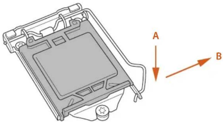
1
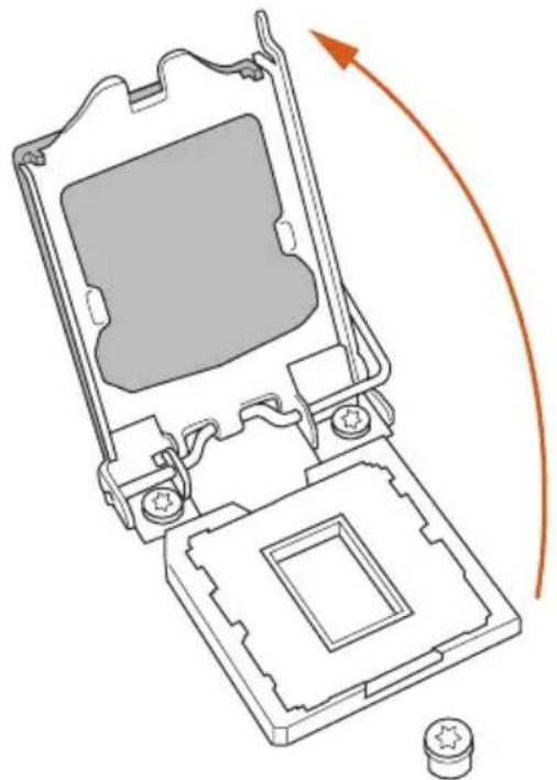
2
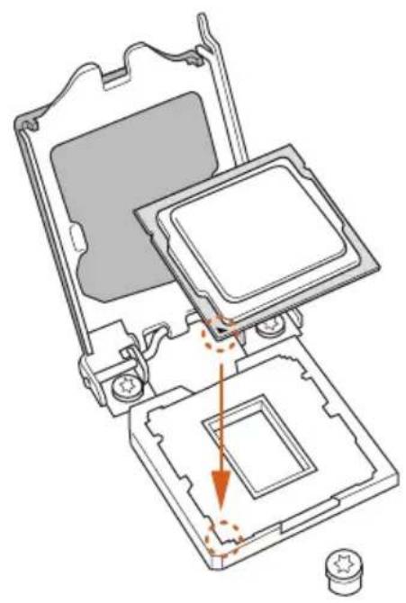
3
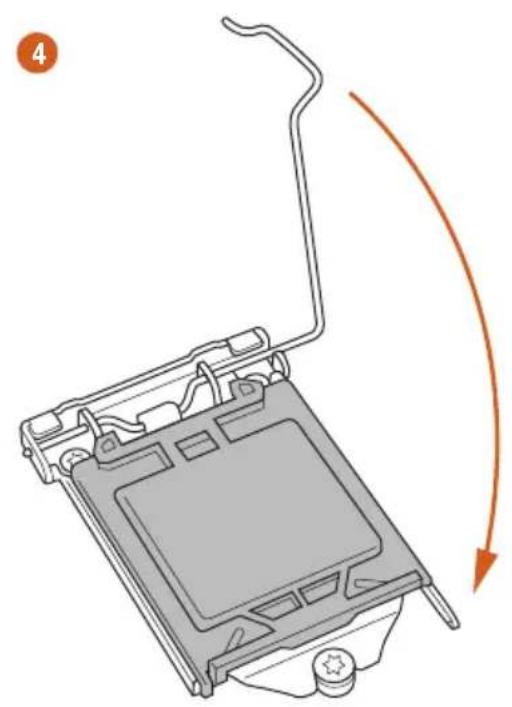
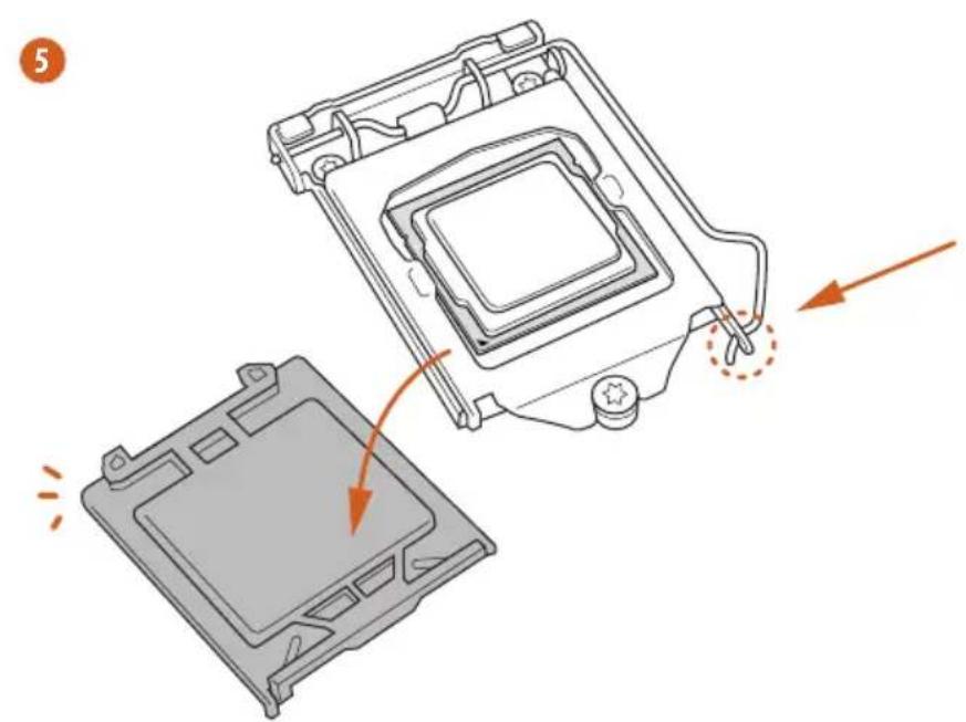

Please save and replace the cover if the processor is removed. The cover must be placed if you wish to return the motherboard for after service.
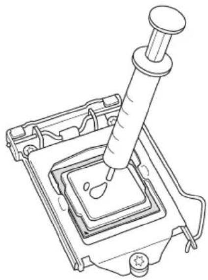
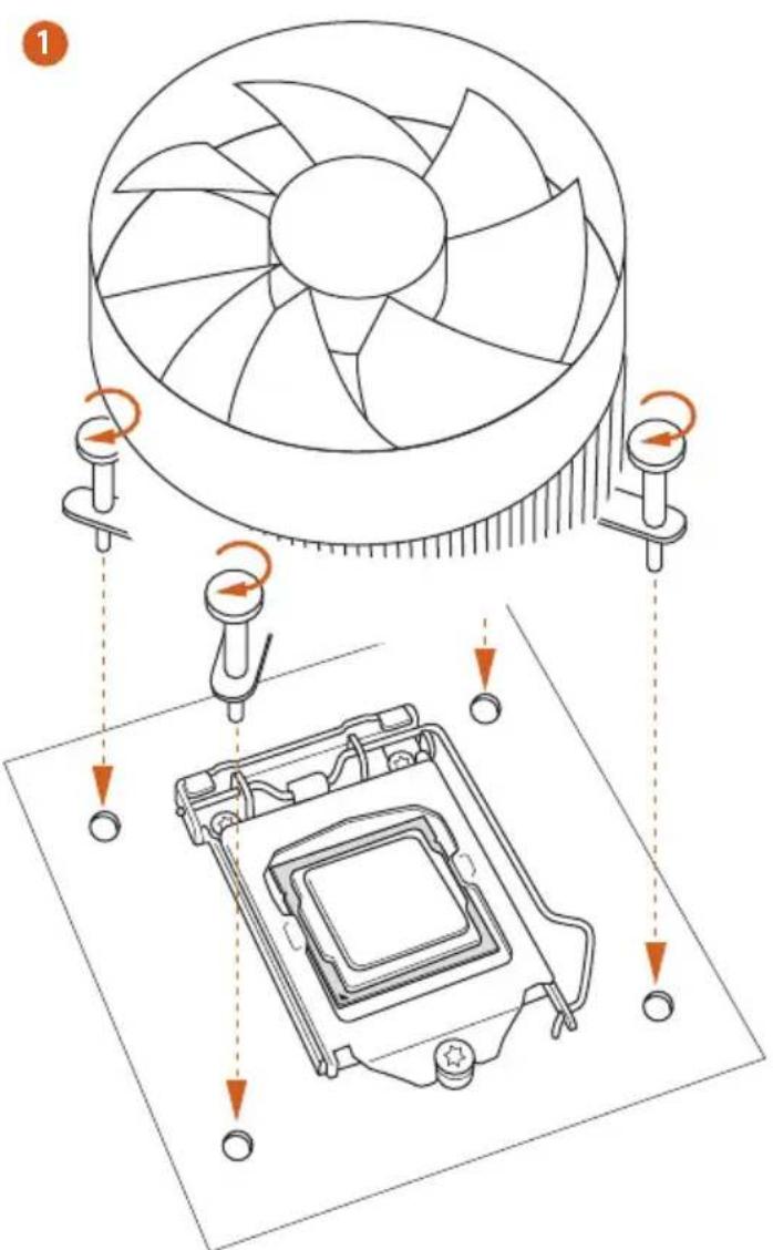
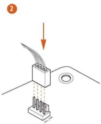
2.2 Installing the CPU Fan and Heatsink
2.3 Installing Memory Modules (DIMM)
This motherboard provides four 240-pin DDR3 (Double Data Rate 3) DIMM slots, and supports Dual Channel Memory Technology.

- For dual channel configuration, you always need to install identical (the same brand, speed, size and chip-type) DDR3 DIMM pairs.
- It is unable to activate Dual Channel Memory Technology with only one or three memory module installed.
- It is not allowed to install a DDR or DDR2 memory module into a DDR3 slot; otherwise, this motherboard and DIMM may be damaged.
Dual Channel Memory Configuration
Priority DDR3_A1 DDR3_A2 DDR3_B1 DDR3_B2
| 1 Populated | Populated | |||
| 2 Populated | Populated | |||
| 3 Populated | Populated | Populated | Populated |

The DIMM only fits in one correct orientation. It will cause permanent damage to the motherboard and the DIMM if you force the DIMM into the slot at incorrect orientation.
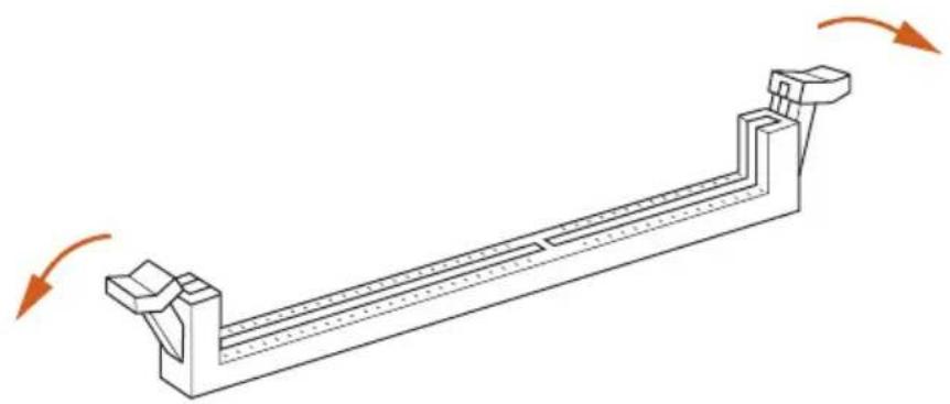
1
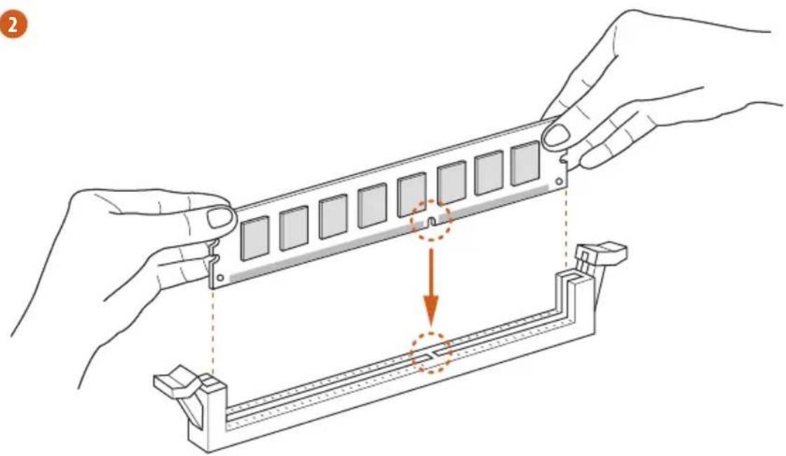
2
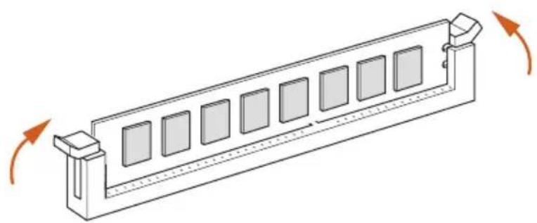
3
2.4 Expansion Slots (PCI and PCI Express Slots)
There are 3 PCI slots and 3 PCI Express slots on the motherboard.

Before installing an expansion card, please make sure that the power supply is switched off or the power cord is unplugged. Please read the documentation of the expansion card and make necessary hardware settings for the card before you start the installation.
PCI slot:
The PCI1, PCI2, and PCI3 slots are used to install expansion cards that have 32-bit PCI interface.
PCIe slots:
PCIE1 (PCIe 2.0 x1 slot) is used for PCI Express x1 lane width cards.
PCIE2 (PCIe 3.0 x16 slot) is used for PCI Express x16 lane width graphics cards.
PCIE3 (PCIe 3.0 x16 slot) is used for PCI Express x8 lane width graphics cards.
PCIe Slot Configurations
PCIE2 PCIE3
Single Graphics Card x16 N/A
Two Graphics Cards in CrossFireXTM or SLI^TM Mode
x8 x8

For a better thermal environment, please connect a chassis fan to the motherboard's chassis fan connector (CHA_FAN1, CHA_FAN2 or CHA_FAN3) when using multiple graphics cards.
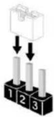
2.5 Jumpers Setup
The illustration shows how jumpers are setup. When the jumper cap is placed on the pins, the jumper is "Short". If no jumper cap is placed on the pins, the jumper is "Open". The illustration shows a 3-pin jumper whose pin1 and pin2 are "Short" when a jumper cap is placed on these 2 pins.
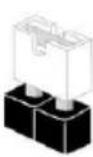
Short
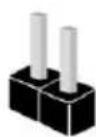
Open
Clear CMOS Jumper (CLRCMOS1)
(see p.1, No. 14)
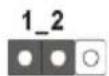
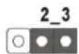
Clear CMOSDefault
CLRCMOS1 allows you to clear the data in CMOS. To clear and reset the system parameters to default setup, please turn off the computer and unplug the power cord from the power supply. After waiting for 15 seconds, use a jumper cap to short pin2 and pin3 on CLRCMOS1 for 5 seconds. However, please do not clear the CMOS right after you update the BIOS. If you need to clear the CMOS when you just finish updating the BIOS, you must boot up the system first, and then shut it down before you do the clear-CMOS action. Please be noted that the password, date, time, and user default profile will be cleared only if the CMOS battery is removed.

The Clear CMOS Switch has the same function as the Clear CMOS jumper.
2.6 Onboard Headers and Connectors

Onboard headers and connectors are NOT jumpers. Do NOT place jumper caps over these headers and connectors. Placing jumper caps over the headers and connectors will cause permanent damage to the motherboard.
System Panel Header (9-pin PANEL1)
(see p.1, No. 12)
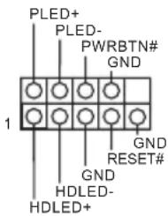
Connect the power switch, reset switch and system status indicator on the chassis to this header according to the pin assignments below. Note the positive and negative pins before connecting the cables.

PWRBTN (Power Switch):
Connect to the power switch on the chassis front panel. You may configure the way to turn off your system using the power switch.
RESET (Reset Switch):
Connect to the reset switch on the chassis front panel. Press the reset switch to restart the computer if the computer freezes and fails to perform a normal restart.
PLED (System Power LED):
Connect to the power status indicator on the chassis front panel. The LED is on when the system is operating. The LED keeps blinking when the system is in S1/S3 sleep state. The LED is off when the system is in S4 sleep state or powered off (S5).
HDLED (Hard Drive Activity LED):
Connect to the hard drive activity LED on the chassis front panel. The LED is on when the hard drive is reading or writing data.
The front panel design may differ by chassis. A front panel module mainly consists of power switch, reset switch, power LED, hard drive activity LED, speaker and etc. When connecting your chassis front panel module to this header, make sure the wire assignments and the pin assignments are matched correctly.
| Power LED Header (3-pin PLED1) (see p.1, No. 13) | PLED PLED PLED+ SATA3_4_5 SATA3_4_5 | Please connect the chassis power LED to this header to indicate the system's power status. |
| Serial ATA3 Connectors (SATA3_0_1: see p.1, No. 9) (SATA3_2_3: see p.1, No. 10) (SATA3_4_5: see p.1, No. 11) | SATA3_0_1SATA3_4_5 | These six SATA3 connectors support SATA data cables for internal storage devices with up to 6.0 Gb/s data transfer rate. |
| USB 2.0 Headers (9-pin USB2_3) (see p.1, No. 16) (9-pin USB4_5) (see p.1, No. 17) | USB PWR P+ GND DUMMY 1 GND P+ GND P- USB PWR | Besides two USB 2.0 ports on the I/O panel, there are two headers on this motherboard. Each USB 2.0 header can support two ports. |
| USB 3.0 Headers (19-pin USB3_4_5) (see p.1, No. 8) | VbusVbus IntA_PB_SSRX- IntA_PB_SSRX+ GND IntA_PB_SSTX- IntA_PB_SSTX+ GND IntA_PB_D- IntA_PB_D+ Dummy | Besides four USB 3.0 ports on the I/O panel, there are one header on this motherboard. Each USB 3.0 header can support two ports. |
| Front Panel Audio Header (9-pin HD_AUDIO1) (see p.1, No. 22) | GND PRESENCE# MIC_RET OUT_RET J_SENSE OUT2_R MIC2_R MIC2_L | This header is for connecting audio devices to the front audio panel. |


- High Definition Audio supports Jack Sensing, but the panel wire on the chassis must support HDA to function correctly. Please follow the instructions in our manual and chassis manual to install your system.
- If you use an AC'97 audio panel, please install it to the front panel audio header by the steps below:
A. Connect Mic_IN (MIC) to MIC2_L
B. Connect Audio_R (RIN) to OUT2_R and Audio_L (LIN) to OUT2_L.
C. Connect Ground (GND) to Ground (GND).
D. MIC_RET and OUT_RET are for the HD audio panel only. You don't need to connect them for the AC'97 audio panel.
E. To activate the front mic, go to the "FrontMic" Tab in the Realtek Control panel and adjust "Recording Volume".
Chassis Speaker Header
(4-pin SPEAKER1)
(see p.1, No. 12)
DUMMY SPEAKER
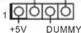
Please connect the chassis
speaker to this header.
SPDIF Out Connector
(2-pin SPDIF_OUT1)
(see p.1, No. 19)
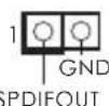
Please connect the
SPDIF_OUT connector of a HDMI VGA card to this header with a cable.
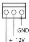
Chassis and Power Fan
Connectors
(4-pin CHA_FAN1)
(see p.1, No. 15)
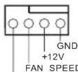
FAN_SPEED_CONTROL
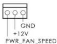
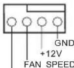
Please connect fan cables to the fan connectors and match the black wire to the ground pin.
(3-pin CHA_FAN2)
(see p.1, No. 2)
(3-pin CHA_FAN3)
(see p.1, No. 24)
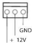
CHA_FAN_SPEED
(3-pin PWR_FAN1)
(see p.1, No. 23)
| CPU Fan Connectors (4-pin CPU_FAN1) (see p.1, No. 3) | GND + 12V CPU_FAN_SPEED FAN_SPEED_CONTROL | This motherboard pro- vides a 4-Pin CPU fan (Quiet Fan) connector. If you plan to connect a 3-Pin CPU fan, please connect it to Pin 1-3. |
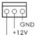
| (3-pin CPU_FAN2) (see p.1, No. 4) | GND + 12V CPU_FAN_speed | This motherboard pro- vides a 24-pin ATX power connector. To use a 20-pin ATX power supply, please plug it along Pin 1 and Pin 13. |
| ATX Power Connector (24-pin ATXPWR1) (see p.1, No. 7) | 12 24 1 13 | This motherboard pro- vides an 8-pin ATX 12V power connector. To use a 4-pin ATX power supply, please plug it along Pin 1 and Pin 5. |
| ATX 12V Power Connector (8-pin ATX12V1) (see p.1, No. 1) | 1 4 5 8 | This motherboard pro- vides an optional wireless transmitting and receiving infrared module. |
| Infrared Module Header (5-pin IR1) (see p.1, No. 20) | IRTX +5VSB DUMMY 1 GND IRRX | This header supports an optional wireless transmitting and receiving infrared module. |
| Serial Port Header (9-pin COM1) (see p.1, No. 21) | RRXD1 DDTR#1 DDS#1 CCTS#1 1 1 1 RR#1 RRTS#1 TTXD1 DDCD#1 | This COM1 header supports a serial port module. |
1 Einleitung
- Extreme Memory Profile (XMP)1.3/1.2
Erweiterungs
steckplatz
1866(OC)/1600/1333/1066
- Extreme Memory Profile (XMP)1.3/1.2
Fente
d'expansion
(PCIE2);double 以 x8(PCIE2)/x8(PCIE3))
TM et CrossFireXTM
TM et SLI TM
Graphiques
(4-KoHTaKTbI, CHA FAN1)
(CM. cTp. 1, N° 15)
(3-KoHTaKTHbI, CHA FAN2)
(CM. cTp. 1, N2)
(3-KOHTaKTHbI, CHA_FAN3)
(CM. cTp. 1, N° 24)
(3-KOHTaKTbI, PWR FAN1)
(CM. cTp. 1, No 23)
FAN_SPEED_CONTROL
IpeHa3HaYeHb IJIa IOKIOUeHn Ka6eIe pa3bEMOB BeHTnIaTOPOB nIOKIOUeHn YepHO rpoBOJa K 3a3eMJIeHNIO.
CHA_FAN_SPEED
PWR_FAN_SPEED
| Pa3bembl BeHTnJIaTOpOB IIII (4-KoHTaKTbI, CPU_ FAN1) (Cm. ctr. 1, № 3) (3-KoHTaKTbI, CPU_ FAN2) (Cm. ctr. 1, № 4) | GND + 12V CPU_FAN_SPEED FAN SPEED_CONTROL | Эта материнская Плata снабжени 4-KoHTaKTbIM pa3bemOM Ддя Малошуmaшero ВeHTnJIaTopa IIII. Еспь Вы сбираетсь ПОдкЛючИТь 3-KoHTaKTbI ВeHTnJIaTOp Поцeccopa, ПОдкЛючAiTe erо к КоHTaKTam 1-3. |
| Pa3bem ПИтань ATX (24-KoHTaKTbI,ATXPWR1) (Cm. ctr. 1, № 7) | 12 1 13 | Эта материнская Плata снабжени 24-KoHTaKTbIM pa3bemOM ПИтань ATX. ЧTo6ы ИСПОЛьЗОВаТь 20-KoHTaKTbI pa3bem ПИтань ATX, ПОдкЛючITE erо ВДОЛь КоHTaKTa 1 и КОHTaKTa 13. |
| Pa3bem ПИтань ATX 12 B (8-KoHTaKTbI,ATX12V1) (Cm. ctr. 1, № 1) | 1 5 8 | Эта материнская Плata снабжени 8-KoHTaKTbIM pa3bemOM ПИтань ATX 12 B. ЧTo6ы ИСПОЛьЗОВаТь 4-KoHTaKTbI pa3bem ПИтань ATX, ПОдкЛючITE erо ВДОЛь КоHTaKTa 1 и КОHTaKTa 5. |
| KoIoДka Инфрарасно MOДУЯ (5-KoHTaKTbIa, IR1) (Cm. ctr. 1, № 20) | IRTX +5VSB DUMMY 1 GND IRRX | Эта кОLOДka ПОДпeржИБаET ДОПОЛНITeьнHuO 6ecпpoвODнHuO пе徳ач Иnprie mсИнhalOB Инфрарасно мОДУЯ. |
| KoIoДka ПосLEДIOВаTEьнHOrO ПорТа (9-KoHTaKTbIa, COM1) (Cm. ctr. 1, № 21) | RRXD1 DDTR#1 DDS#1 CCTS#1 RRI#1 GND TTXD1 DDCD#1 | КоLOДka COM1 ПОдпeржИБaET ПОдКЛючЕнe мОДУЯ ПОсLEДIOВаTEьнHOrO ПорТa. |
1 Introdução
1866(OC)/1600/1333/1066 ECC olmayan, ara bellege
PLED (Sistem Güci LED):
Guc durumu belirtecini kasa on paneline baglayn. Sistem calisirken LED isigt yanacaktir. Sistem S1/S3 uyku durumdayken LED isigt yanp soner. Sistem S4 uyku durumunda ya da kapalyken (S5) LED isikapanir.
HDLED (Sabit Disk Aktivitesi LED):
Sabit Disk Aktivitesi LED'i kasanin on paneline baglayin. Sabit surucu veri okur ya da yazarken LED 1sigt yanar.
1866(OC)/1600/1333/1066 ECC, ECC
HDLED( hdt 30000000000000000000000000000000000000000000000000000000000000000000000000
韩,
| 1. 고등을 기재해드는 키zag이를 기재해드는 썸서의 키zag이에어 가 HDA를 기재해드는 썸서에 썸서의 키zag이에 어 斯라울 썸서에 썸서에 썸서에 2. AC'97 오리오 키zag이에 thro해드는 썸서에 thro해드는 썸서에 thro해드는 thro해드는 thro해드는 thro해드는 thro해드는 thro해드는 thro해드는 thro해드는 thro해드는 thro해드는 thro해드는 thro해드는 thro해드는 thro해드는 thro해드는 thro해드는 thro해드는 thro해드는 thro해드는 thro해드는 thro해드是在 thro해드 thro해드 thro해드 thro해드 thro해드 thro해드 thro해드 thro해드 thro해드 thro해드 thro해드 thro해드 thro해드 thro해드 thro해드 thro해드 thro해드 thro해드 thro해드 thro해드 thro해드 thro해드 thro해드 thro해드 thro해드 thro해赎 thro해赎 thro해赎 thro해赎 thro해赎 thro해赎 thro해赎 thro해赎 thro해赎 thro해赎 thro해赎 thro해赎 thro해赎 thro해赎 thro해赎 thro해赎 thro해赎 thro해赎 thro해赎 thro해赎 thro해赎 thro해赎 thro해赎 thro해赎 thro해赎 thro해elve thro해赎 thro해赎 thro해赎 thro해赎 thro해赎 thro해赎 thro해赎 thro해赎 thro해赎 thro해赎 thro해赎 thro해赎 thro해赎 thro해赎 thro해赎 thro해赎 thro해赎 thro해赎 thro해赎 thro해赎 thro해赎 thro해赎 thro해赎 thro해赎 thro해赎回 thro해赎 thro해赎 thro해赎 thro해赎 thro해赎 thro해赎 thro해赎 thro해赎 thro해赎 thro해赎 thro해赎 thro해赎 thro해赎 thro해赎 thro해赎 thro해赎 thro해赎 thro해赎 thro해赎 thro해赎 thro해赎 thro해赎 thro해赎 thro해赎 thro해赋 thro해赎 thro해赎 thro해赎 thro해赎 thro해赎 thro해赎 thro해赎 thro해赎 thro해赎 thro해赎 thro해赎 thro해赎 thro해赎 thro해赎 thro해赎 thro해赎 thro해赎 thro해赎 thro해赎 thro해赎 thro해赎 thro해赎 thro해赎 thro해赎 thro해赚 thro해赎 thro해赎 thro해赎 thro해赎 thro해赎 thro해赎 thro해赎 thro해赎 thro해赎 thro해赎 thro해赎 thro해赎 thro해赎 thro해赎 thro해赎 thro해赎 thro해赎 thro해赎 thro해赎 thro해赎 thro해赎 thro해赎 thro해赎 thro해赎 thro해贱 thro해赎 thro해赎 thro해赎 thro해赎 thro해赎 thro해赎 thro해赎 thro해赎 thro해赎 thro해赎 thro해赎 thro해赎 thro해赎 thro해赎 thro해赎 thro해赎 thro해赎 thro해赎 thro해赎 thro해赎 thro해赎 thro해赎 thro해赎 thro해赎 thro해対 thro해赎 thro해赎 thro해赎 thro해赎 thro해赎 thro해赎 thro해赎 thro해赎 thro해赎 thro해赎 thro해赎 thro해赎 thro해赎 thro해赎 thro해赎 thro해赎 thro해赎 thro해赎 thro해赎 thro해赎 thro해赎 thro해赎 thro해赎 thro해赎 thro해狱 thro해赎 thro해赎 thro해赎 thro해赎 thro해赎 thro해赎 thro해赎 thro해赎 thro해赎 thro해赎 thro해赎 thro해赎 thro해赎 throhea throhea throhea throhea throhea throhea throhea throhea throhea throhea throhea throhea throhea throhea throhea throhea throhea throhea throhea throhea throhea throhea throhea throhea throhea throhea throhea throhea throhea throhea throhea throhea throhea throhea throhea throhea throhea throhea throhea throhea throhea throhea throhea throhea throhea throhea throhea throhea throhea throhea throhea throhea throhea throhea throhea throhea throhea throhea throhea throhea throhea throhea throhea throhea throhea throhea throhea thro thro thro thro thro thro thro thro thro thro thro thro thro thro thro thro thro thro thro thro thro thro thro thro thro thro thro thro thro thro thro thro thro thro thro thro thro thro thro thro thro thro thro thro thro thro thro thro thro thro thro thro thro thro thro thro thro thro thro thro thro thro thro thro thro thro thro thro thro thro thro thro thro thro thro thro thro thro thro thro thro thro thro thro thro thro thro thro thro thro thro thro thro thro thro thro thro thro thro thro thro thro thro thro thro thro thro thro thro thro thro thro thro thro thro thro thro thro thro thro thro thro thro thro thro thro thro thro thro thro thro thro thro thro thro thro thro thro thro thro thro thro thro thro thro thro thro thro thro thro Kro GND +12V FAN_SPEED +12V GND +12V CHA_FAN_SPEED | |
| 3개지 4개지 (1개지,12개 19개 19개 19개 19개 19개 19개 19개 19개 19개 19개 19개 19개 19개 19개 19개 19개 19개 +12V CHA_FAN_SPEED |
Extreme Memory Profile (XMP)1.3/1.2
扩充槽
双 - x8 (PCIE2) / x8 (PCIE3))
TM和CrossFireXTM
TM和 SLI^TM
图形
效和 VGA 输出。
采用AVC · MVC(S3D)和MPEG-2FullHWEncode1
Intel® InTruTM 3D、Intel® Clear Video HD 技术、Intel®
InsiderTM、Intel® HD Graphics 4400/4600
(4096x2304)
SyncDeepColor(12bpc),xvYCC和HBR(高位速率音频)
播放。
音频
频编 解码 器)
LAN
后面板I/O
LED)
器/麦克风
存储
K-Series unlocked CPU
晶片組
Z87
記憶體
- Extreme Memory Profile (XMP)1.3/1.2
擴充插槽
RESET (Switch Atur Ulang):
If you need to contact ASRock or want to know more about ASRock, you're welcome to visit ASRock's website at http://www.asrock.com; or you may contact your dealer for further information. For technical questions, please submit a support request form at http://www.asrock.com/support/tsd.asp
ASRock Incorporation
2F., No.37, Sec. 2, Jhongyang S. Rd., Beitou District,
Taipei City 112, Taiwan (R.O.C.)
ASRock EUROPE B.V.
Bijsterhuizen 3151
6604 LV Wijchen
The Netherlands
Phone: +31-24-345-44-33
Fax: +31-24-345-44-38
ASRock America, Inc.
13848 Magnolia Ave, Chino, CA91710
U.S.A.
Phone: +1-909-590-8308
Fax: +1-909-590-1026
For the following equipment:
Motherboard
(Product Name)
Z87 Extreme3 / ASRock
(Model Designation / Trade Name)
ASRock Incorporation
(Manufacturer Name)
2F., No.37, Sec. 2, Zhongyang S. Rd., Beitou District, Taipei City 112, Taiwan (R.O.C.)
(Manufacturer Address)
is herewith confirmed to comply with the requirements set out in the Council
Directive on the Approximation of the Laws of the Member States relating to
Electromagnetic Compatibility Directive (2004/108/EC) and Safety Directive (2006/95/
EC), the following standards are applied:
EN 55022:2006+A1:2007
EN 61000-3-2:2009
EN 61000-3-3:2008
EN 55024:1998 + A1:2001 + A2:2003
IEC 61000-4-2: 2008;
IEC 61000-4-3:2010;IEC 61000-4-4:2010
IEC 61000-4-5:2005; IEC 61000-4-6:2008
IEC 61000-4-8:2009;IEC 61000-4-11:2004
EN 60950-1:2005 + A1:2009
IEC 60950-1:2006 + A11:2009 + A1:2010 + A12:2011
The following manufacturer / importer or authorized representative established within the EUT is responsible for this declaration:
ASRock EUROPE B.V.
(Company Name)
Bijsterhuizen 3151 6604 LV Wijchen The Netherlands
(Company Address)
Person responsible for making this declaration:

(Name, Surname)
A.V.P
(Position / Title)
Apr. 26, 2013
(Date)
- Copyright Notice:
- Disclaimer:
- CALIFORNIA, USA ONLY
- AUSTRALIA ONLY
- No. Description
- No. Description No. Description
- Chapter 1 Introduction
- Package Contents
- Specifications
- Platform
- A-Style
- CPU
- Chipset
- Memory
- Expansion
- Slot
- Graphics
- Audio
- LAN
- Storage
- Connector
- Support
- CD
- Hardware
- Monitor
- os
- Certifica
- tions
- Unique Features
- ASRock A-Tuning
- ASRock Instant Flash
- ASRock APP Charger
- ASRock XFast USB
- ASRock XFast LAN
- ASRock XFast RAM
- ASRock Crashless BIOS
- ASRock OMG (Online Management Guard)
- ASRock Internet Flash
- ASRock UEFI System Browser
- ASRock Dehumidifier Function
- ASRock Easy RAID Installer
- ASRock Easy Driver Installer
- ASRock Interactive UEFI
- ASRock Fast Boot
- ASRock Restart to UEFI
- ASRock Good Night LED
- ASRock USB Key
- ASRock Home Cloud
- ASRock FAN-Tastic Tuning
- Chapter 2 Installation
- Pre-installation Precautions
- Installing the CPU
- Installing the CPU Fan and Heatsink
- Installing Memory Modules (DIMM)
- Dual Channel Memory Configuration
- Priority DDR3_A1 DDR3_A2 DDR3_B1 DDR3_B2
- Expansion Slots (PCI and PCI Express Slots)
- PCI slot:
- PCIe slots:
- PCIe Slot Configurations
- PCIE2 PCIE3
- Jumpers Setup
- Onboard Headers and Connectors
- PWRBTN (Power Switch):
- RESET (Reset Switch):
- PLED (System Power LED):
- HDLED (Hard Drive Activity LED):
- Einleitung
- Erweiterungs
- steckplatz
- Fente
- d'expansion
- Graphiques
- Introdução
- PLED (Sistem Güci LED):
- HDLED (Sabit Disk Aktivitesi LED):
- HDLED( hdt 30000000000000000000000000000000000000000000000000000000000000000000000000
- 扩充槽
- 图形
- 音频
- 后面板I/O
- 存储
- RESET (Switch Atur Ulang):
- ASRock Incorporation
- ASRock EUROPE B.V.
- ASRock America, Inc.
- Motherboard
- Z87 Extreme3 / ASRock
- 2F., No.37, Sec. 2, Zhongyang S. Rd., Beitou District, Taipei City 112, Taiwan (R.O.C.)
- Bijsterhuizen 3151 6604 LV Wijchen The Netherlands
- A.V.P
- Apr. 26, 2013
Brand : ASROCK
Model : Z87 Extreme3
Category : Motherboard