
POOLEX MAG FI - Pool heat pump POOLSTAR - Free user manual and instructions
Find the device manual for free POOLEX MAG FI POOLSTAR in PDF.
Download the instructions for your Pool heat pump in PDF format for free! Find your manual POOLEX MAG FI - POOLSTAR and take your electronic device back in hand. On this page are published all the documents necessary for the use of your device. POOLEX MAG FI by POOLSTAR.
USER MANUAL POOLEX MAG FI POOLSTAR
This heat pump contains a flammable refrigerant R32. Any intervention on the refrigerant circuit is prohibited without a valid autho- rization. Before working on the refrigerant circuit, the following precautions are neces- sary for safe work.
The work must be carried out according to a controlled procedure, in order to mini- mize the risk of presence of flammable gases or vapors during the execution of the works.
2. General work area
All persons in the area must be informed ofthe nature ofthe work in progress. Avoid working in a confined area. The area around the work area should be divided, secured and special attention should be paid to nearby sources of flame or heat.
3. Verification of the presence of refrigerant
The area should be checked with a suitable refrigerant detector before and during work to ensure that there is no potentially flammable gas. Make sure that the leak detection equipment used is suitable for flammable refrigerants, ie it does not produce sparks, is properly sealed or has intemal safety.
4. Presence of fire extinguisher
f hot work is to be performed on the refrigeration equipment or any associated part, appropriate fire extin- guishing equipment must be available. Install a dry powder or CO2 fire extinguisher near the work area.
5. No source of flame, heat or spark
It is totally forbidden to use a source of heat, flame or spark in the direct vicinity of one or more parts or pipes containing or having contained a flammable refrigerant. All sources of ignition, including smoking, must be sufficiently far from the place of installation, repair, removal and disposal, during which time a flammable refrigerant may be released into the surrounding area. Before starting work, the environment of the equipment should be checked to ensure that there is no risk of flammability. «No smoking» signs must be posted.
Make sure the area is in the open air or is properly ventilated before working on the system or performing hot work. Some ventilation must be maintained during the duration of the work.
7. Control of refrigeration equipment
When electrical components are replaced, they must be suitable for the intended purpose and the appro- priate specifications. Only the parts of the manufacturer can be used. f in doubt, consult the technical service ofthe manufacturer. The following controls should be applied to installations using flammable refrigerants: - The size of the load is in accordance with the size of the room in which the rooms containing the refrigerant are installed; - Ventilation and air vents work properly and are not obstructed; - Hf an indirect refrigeration circuit is used, the secondary circuit must also be checked. - The marking on the equipment remains visible and legible. Illegible marks and signs must be corrected: - Refrigeration pipes or components are installed in a position where they are unlikely to be exposed to a substance that could corrode components containing refrigerant
8. Verification of electrical appliances
Repair and maintenance of electrical components must include initial safety checks and component inspection procedures. If there is a defect that could compromise safety, no power supply should be connected to the circuit until the problem is resolved. Initial security checks must include: + That the capacitors are discharged: this must be done in a safe way to avoid the possibility of sparks: + No electrical components or wiring are exposed during loading, recovery or purging of the refrigerant gas system: + There is continuity of grounding.
Dear Customer, Thank you for your purchase and for your confidence in our products. These are the result of many years of research in the field of design and production of heat pumps for swimming pools. Our aim is to provide you with an exceptional high performance quality product. We have produced this manual with the utmost care so that you get maximum benefit from your Poolex heat pump. ENI ‘
These installation instructions are an integral part of the product. They must be given to the installer and retained by the user. the manual is lost, please consult the website: www.poolex.fr The instructions and recommendations contained in this manual should be read carefully and understood since they provide valuable information concerning the heat pump's safe handling and operation. Keep this manual in an accessible place for easy future reference. Installation must be carried out by a qualified professional person in accordance with current regulations and the manufacturer's instructions. An installation error may cause physical injury to persons or animals as well as mechanical damage for which the manufacturer can under no circumstances be held responsible. After unpacking the heat pump, please check the contents in order to report any damage. Prior to connecting the heat pump, ensure that the information provided in this manual is compat- ible with the actual installation conditions and does not exceed the maximum limits authorized for this particular product. In the event of a defect and/or malfunction of the heat pump, the electricity supply must be disconnected and no attempt made to repair the fault. Repairs must be undertaken only by an authorized technical service organization using original replacement parts. Failure to comply with the above-mentioned clauses may have an adverse effect on the heat pump's safe operation. To guarantee the heat pump's efficiency and satisfactory operation, it is important to ensure its regular maintenance in accordance with the instructions provided. Ifthe heat pump is sold or transferred, always make sure that all technical documentation is transmitted with the equipment to the new owner. This heat pump is designed solely for heating a swimming pool. Any other use must be considered as being inappropriate, incorrect or even hazardous. Any contractual or non-contractual liability of the manufacturer/distributor shall be deemed null and void for damage caused by installation or operational errors, or due to non-compliance with the instructions provided in this manual or with current installation norms applicable to the equipment covered by this document. 21EN
1.1 General Terms of Delivery 4
12 Safety instructions 4 13 Water treatment 5
2.1 Package contents 6
2.2 General characteristics 6
6. Maintenance and servicing 23
6.1 Maintenance, servicing and winter storage 23
7.1 Breakdowns and faults 24
8 Recycling 25 81 Recycling the heat pump 25
9.1 General warranty conditions 26
1.1 General Terms of Delivery
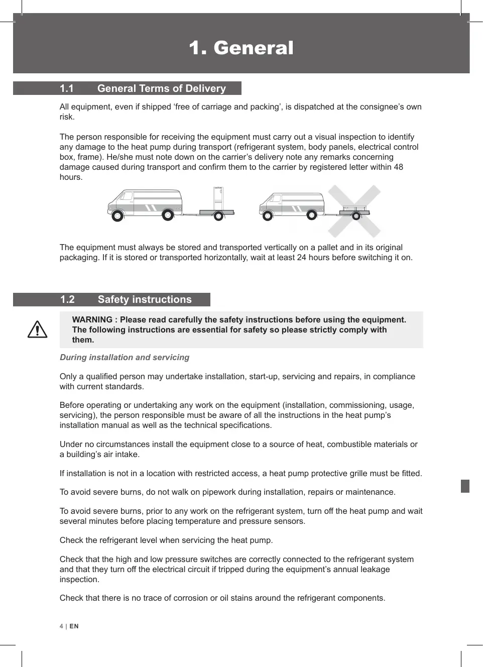
Al equipment, even if shipped ‘free of carriage and packing', is dispatched at the consignee's own risk. The person responsible for receiving the equipment must carry out a visual inspection to identify any damage to the heat pump during transport (refrigerant system, body panels, electrical control box, frame). He/she must note down on the carrier's delivery note any remarks conceming damage caused during transport and confirm them to the carrier by registered letter within 48 hours. The equipment must always be stored and transported vertically on a pallet and in its original packaging. it is stored or transported horizontally, wait at least 24 hours before switching it on. Safety instruction
WARNING : Please read carefully the safety instructions before using the equipment.
The following instructions are essential for safety so please strictly comply with them. During installation and servicing Only a qualified person may undertake installation, start-up, servicing and repairs, in compliance with current standards. Before operating or undertaking any work on the equipment (installation, commissioning, usage, servicing), the person responsible must be aware of all the instructions in the heat pump's installation manual as well as the technical specifications. Under no circumstances install the equipment close to a source of heat, combustible materials or a building's air intake. installation is not in a location with restricted access, a heat pump protective grille must be fitted. To avoid severe burns, do not walk on pipework during installation, repairs or maintenance. l To avoid severe burns, prior to any work on the refrigerant system, turn off the heat pump and wait several minutes before placing temperature and pressure sensors. Check the refrigerant level when servicing the heat pump. Check that the high and low pressure switches are correctly connected to the refrigerant system and that they turn off the electrical circuit if tripped during the equipment's annual leakage inspection. Check that there is no trace of corrosion or oil stains around the refrigerant components. AIEN
During use To avoid serious injuries, never touch the fan when it is operating. Keep the heat pump out of the reach of children to avoid serious injuries caused by the heat exchanger's blades. Never start the equipment if there is no water in the pool or if the circulating pump is stopped. Check the water flow rate every month and clean the filter if necessary. During cleaning Switch off the equipment’ electricity Supply. Close the water inlet and outlet valves. Do not insert anything into the air or water intakes or outlets. Do not rinse the equipment with water. During repairs Carry out work on the refrigerant system in accordance with current safety regulations. Brazing should be performed by a qualified welder. When replacing a defective refrigerant component, use only parts certified by our technical department. When replacing pipework, only copper pipes conforming to Standard NF EN12735-1 may be used for repairs. When pressure-testing to detect leaks: To avoid the risks of fire or explosion, never use oxygen or dry air. Use dehydrated nitrogen or a mixture of nitrogen and refrigerant. The low and high side test pressure must not exceed 42 bar.
Poolex heat pumps for swimming pools can be used with all types of water treatment systems. Nevertheless, it is essential that the treatment system (chlorine, pH, bromine and/or salt chlorina- tor metering pumps) is installed after the heat pump in the hydraulic circuit. eatmen To avoid any deterioration to the heat pump, the water’s pH must be maintained between
2.1 Package contents C]
Heat pump Poolex MAG FI 2 hydraulic inletoutlet connectors 32/38mm diameter This installation and user manual 4 anti-vibration pads
2.2 General characteristics
A Poolex heat pump has the following features: + CE certification and complies with the RoHS European directive. + High performance with up to 80% energy savings compared to a conventional heating system. Clean, efficient and environmentally friendly R32 refrigerant. Reliable high output leading brand compressor. Wide hydrophilic aluminum evaporator for use at low temperatures. User-friendly intuitive control panel. Heavy duty shell, anti-UV treated and easy to maintain. \ARAAAA, Designed to be silent. GIEN
2.3 echnical cifications
Heating power (KW) 17-41 21-51 Ar 0260 [Consumption (kW) 0136-0721 168-0898 Water € 26°C :. [Heating power (kW) 1.06-3.0 1.36-3.8 das c Consumption (kW) 0.151-0.666 0194-0844 COP (Coeff. of performance) 7.0-4.5 7.0-4.5 Cooling capacity (kW) 0.91-25 11-80 Ar 0880 [Consumption (kW) 0.182-0.883 0.262-1.00 Water E: 27°C Electrioity supply 220-240V single-phase - 50Hz Maximum power (AW) 12 15 Maximum current (A) 54 69 Heating temperature range 10°C - 40°C Operating range 10°C - 43°C Unit dimensions L x W x H (mm) 420x290x430 470x290x430 Unit weight (kg) 215 23.5 Sound pressure level at 10 m (ABA) © 2 2 Hydraulic connection (mm) PVC 321 38mm Heat exchanger PVC tank and titanium heating coil Min. water flow rate (m/h) 2 25 Compressor type Rotatif Refrigerant R32 Waterproof IP. IPX4 Load loss (MCE) 11 12 Max. pool volume (m°) 2 35 Control panel Screen LED Mode Heating / Cooling / Auto The technical specifications of our heat pumps are provided for information purposes only. We reserve the right to make changes without prior notice. ‘Ambient air temperature Z'Initial water temperature 5 Noise at 10 m in accordance with Directives EN ISO 3741 and EN ISO 354 « Calculated for an in-ground private swimming pool covered with a bubble cover. ENI7
The heat pump is very easy to install, only water and power need to be connected during installation ocation The heat pump should be located at least 2.5 meter away from the swimming pool. >2.5m Pool Please comply with the following rules concerning the choice of heat pump location.
1. The units future location must be easily accessible for convenient operation and maintenance.
2. It must be installed on the ground, laid ideally on a level concrete floor. Ensure that the floor is
suficiently stable and can support the weight of the unit.
3. Check that the unit is properly ventilated, that the air outlet is not facing the windows of neigh-
boring buildings and that the exhaust air cannot return. In addition, provide sufficient space around the unit for servicing and maintenance operations.
4. The unit must not be installed in an area exposed to oil, flammable gases, corrosive products,
sulfurous compounds or close to high frequency equipment.
5. To prevent mud splashes, do not install the unit near a road or track.
6. To avoid causing nuisance to neighbors, make sure the unit is installed so that it is positioned
towards the area that is least sensitive to noise.
7. Keep the unit as much as possible out of the reach of children.
Dimensions in mm Place nothing less than 1,50 m in front of the heat pump. Leave 30 cm of empty space around the sides and rear of the heat pump. Do not leave any obstacle above or in front of the unit! 101EN
Automated treatment system
The filter located upstream of the heat pump must be regularly cleared so that the water in the system is clean, thus avoiding the operational problems associated with dirt or clogging in the filter. Hydraulic connection Step 1 Step 2 Screw the connectors to the heat pump Connect the water outlet pipe and the water intake pipe Electrical connection The heat pump electrical plug integrates Power Test pump plug integ indicator a 10mA differential circuit breaker. Before connecting your heat pump, please ensure that the plug is connected to the ground. The filter pump should function at the same time as the heat pump. Therefore, you need to connect them to the same electrical circuit. Reset ENI 11
ol panel E Mode Cooling Mode Auto Mode Heating Bouton “Mode” Bouton “+” Bouton “ON/OFF" Bouton “-" To lock or unlock the control panel, press (&) + @) 3s. Operating mode selector Before starting, ensure that the filtration pump is working and that water is circulating through the heat pump. Prior to setting your required temperature, you must first select an operating mode for your remote contrl, Heating Mode Select the heating mode for the heat pump to heat the water in E your pool. Cooling Mode Select the cooling mode for the heat pump to cool the water in your pool. Mode Auto Choose auto mode for the heat pump to intelligentiy change mode. 121EN
Step 1 : Press ()) to switch on your pump. Step 2: Press [(@) to switch from one mode to another until the heating mode is displayed. Step 3 : Using buttons oO) and (Q] select the required temperature. EXAMPLE: Ifthe current temperature is 15°C, default setting temperature is 27° required temperature is 30°C. Current water Required temperature temperature Useful information about how the heating mode operates When the incoming water temperature is less than or equal to the required temperature (setpoint temperature) -X°C, the heat pump will switch to heating mode. The compressor will stop when the temperature of the incoming water is greater than or equal to the required temperature (setpoint temperature). Indicators for adjustment range X X : adjustable parameter from 0° to 10°C, default setting is 1°C. 44 Cooling mode (Full Inverter) Step 1 : Press ({)) to switch on your pump. Step 2 : Press ({) to switch from one mode to another until the cooling mode is displayed. Step 3 : Using buttons © and © select the required temperature. EXAMPLE : Ifthe current temperature is 30°C, default setting temperature is 27° required temperature is 15°C. EN 13
1 Downloading & Installing the «Smart Life» app About the Smart Life app: You’ need to create a «Smart Life» account to control your heat pump remotely. The «Smart Life» app lets you control your home appliances from anywhere. You can add and control multiple devices at once. - Also compatible with Amazon Echo and Google Home (depending on the country). - You can share your devices with other Smart Life accounts. - Receive real-time operational alerts. - Create scenarios with several devices, depending on the app's weather data (geolocation required). For more information, go to the «Help» section of the «Smart Life» app The «Smart Life» app and services are provided by Hangzhou Tuya Technology. Poolstar, owner and distributor of the Poolex brand, cannot be held responsible for the operation of the «Smart Life» app. Poolstar has no visibility on your «Smart Life» account. ios : Search for «Smart Life» in the App Store to download the app: Smar Lite Check the compatibility of your phone and the version of your OS before installing the application Android : Search for «Smart Life» on Google Play to download the app : V4 Sman Lite Check the compatibility of your phone and the version of your OS before installing the application 141EN
Seti g up the app A WARNING : Before you begin, make sure you have downloaded the «Smart Life» app, connected to your local WiFi network, and that your heat pump is electrically powered and running. You’ need to create a «Smart Life» account to control your heat pump remotely. If you already have a Smart Life account, please log in and go directly to step 3. Step 1 : Click on «Create new account» and choose to register by «Email» or «Phone,» where a verification code will be sent to you. Enter your email address or phone number and click «Send verification code». < Email Téléphone Inscription par email France 422
Step 2 : Enter the verification code received by email or phone to validate your account. Congratulations! You are now part of the «Smart Life» community. ENI 15
4.5.3 Pairing the heat pump
EZ Mode Step 1 : Now start the pairing. Choose your home WiFi network, enter the WiFi password and press «Confirm». Step 2 : Activate the pairing mode on your heat pump according to the following procedure: The procedure depends on the model of your control box: À\ SAUTION The «Smart Life» application only supports 2.4GHz WiFi networks. If your WiFi network uses the GHz frequency, go to the interface of Entrer le mot de passe Wi-Fi Support ouate réseau VF Lau your home WiFi network to create a second 2.4GHz WiFi network (available for most Intemet boxes, routers and WiFi access points). paired. Press (2) + (0) simultaneously for 5s, & flashes quickly, the control unit is ready to be The pairing is successful, you can rename your Poolex heat pump then press «Done». Congratulations, your heat pump can now be controlled from your smartphone. < Ajouter Poor o ensoleille Ajout de l'appareil réussi Toul apr Salon Chambre cc Ê h ©
Note: The flashing stops when the box is connected to WiFi EN 17
Interface © Current pool temperature © Temperature setpoint © Current operating mode © Switch the heat pump onVoff @ Change the temperature @ Change the operating mode @ Set the operating range Configure the operating ranges for the heat pi Step 1 : Create a schedule, choose the time, day(s) of the week(s), and the action (turn on or off) and save. ump Ajout dune programmation or < Ajout dun minuteur < Ajout dun minuteur Sauvegarder Dimanche Lundi Mardi Mercredi Vendredi Samedi Répéter Step 2 : To delete a time slot, press on it and hold. 181EN
Choice of operating modes For On/Off heat pumps: You can choose between Auto, Heating, or Cooling modes. Auto Mode Cooling Mode Heating Mode Done Available modes Auto Cooling Heating ENI 19
Auto mode (Full Inverter) Step 1 : Press ({)) to switch on your pump. Step 2 : Press (fl) to switch from one mode to another unti the auto mode is displayed. Step 3 : Using buttons © and © select the required temperature. EXAMPLE : Ifthe current temperature is 30°C, default setting temperature is 27° required temperature is 15°C.
A WARNING: This operation is used to assist servicing and future repairs. The default settings should only be modified by an experienced professional person. The system's settings can be checked and adjusted via the remote control by following these steps Step 1 : Keep pressing 3s until you enter the settings verification mode. Step 2: Press © and for see the parameters. Step 3 : Press ((j) to select the setting to be modified. Step 4 : Press (2) and (+) to adjust the setting value. Step 6 : Press (()) to return to the main screen. Step 5 : Press to set the new value. F50 F52 F53 F54 FS9 F70 F71 F72 F73 F74 F75 F76 F77 F80 F81 Range Default Ft Heating setting temperature 20-40 [°c 27 F2 Cooling setting temperature 10-30 | °c 27 F4 Set temperature in automatic mode ETES 27 F5 Linkage switch function 02 1 o F6 Return differential temperature in heating mode 00 |c 1 F7 Return differential temperature in cooling mode oo |°c 1 F9 Return differential temperature in automatic mode 010 |'c 2 F0 Upper heating temperature 20-80 [°c 40 GI Lower cooling temperature 5-30 |°c 10 F21 Pump interval running time 0=120 | Min 5 F22 Ambient temperature for enabling auxliary electric heating -50-30 [°C -20 F23 Temperature compensation value 0-10 [°c o F40 Coil temperature for starting defrosting 30-15 |-c 3 FAî Coil temperature for exiting defrosting CTMES 15 F42 Ambient temperature to allow defrosting -30-30 [°c 10 The set difference between the ambient temperature and the coil « ras temperature for starting defrosting ” 920 j"e 2 The over heating temperature of difference between ambient F44 temperature and coil temperature at which defrostingis started in | 0-20 |°C 2 advance F45 Compressor operation cycle of entering the defrosting 1-240 | Min 40 F46 Defrosting running time, 0 is to cancel the defrosting function 0-99 | Min 8 F51 Main valve regulating cycle 10-120 | Sec 30 F55 Target superheat when heating 10-10 [°c 2 F56 Target superheat when cooling 0-15 [°c 0 F57 Minimum opening of main valve when cooling 0-480 [P 100 F58 Minimum opening of main valve when heating 0-480 |P 70 F78 Extended parameter - The serial number of the parameter 02999 o F79 Extended parameters - The set data 0-9999 o Reserved, do not modify : F3 F8 F 12 17 F20 F24 F26F20 F27 F28 F20 F30 O1 F2 09 F04 FDF 00 FAT AS ENI 21
Conditions of use For the heat pump to operate normally, the ambient air temperature must be between -10°C and 43°C. Recommendations prior to start-up Before activating the heat pump, please: Check that the unit is stable. Control the proper functioning of your electrical installation. Check that the hydraulic connections are tight and that there is no leakage of water. Remove any unnecessary object or tool from around the unit. Operation
Connect the unit power plug. Activate the circulating pump. Activate the units power supply protection (differential switch and circuit-breaker). Activate the heat pump. Select the required temperature. The heat pump's compressor will start up after a few moments. All you have to do now is wait until the required temperature is reached.
WARNING: Under normal conditions, a suitable heat pump can heat the water in
a swimming pool by 1°C to 2°C per day. It is therefore qui normal to not feel any temperature difference in the system when the heat pump is working. A heated pool must be covered to avoid any loss of heat. Good to know restarting after power failure After power failure or abnormal shutdown, power on again, the system is in standby state. Reset the differential plug and turn on the heat pump. 221 EN
6. Maintenance and servicing
g and winter storage maintenance work on the unit, ensure that you have disconnected the electrical power supply. Cleaning The heat pump's casing must be cleaned with a damp cloth. The use of detergents or other household products could damage the surface of the casing and affect its properties. The evaporator at the rear of the heat pump must be carefully cleaned with a vacuum cleaner and soft brush attachment. Annual maintenance The following operations must be undertaken by a qualified person at least once a year. Carry out safety checks. Check the integrity of the electrical wiring. Check the earthing connections. Monitor the state of the pressure gauge and the presence of refrigerant. Winter storage Your heat pump is designed to operate in rainy weather conditions and withstand frost using a specially created anti-frost technology. However it is not recommended to leave it outside for long periods of time (eg over winter). After draining down the pool for the winter, store the heat pump in
WARNING: Under normal conditions, a suitable heat pump can heat the water in E
ÂA a swimming pool by 1°C to 2°C per day. It is therefore quite normal to not feel any temperature difference in the system when the heat pump is working. A heated pool must be covered to avoid any loss of heat.
7.1 Breakdowns and faults
8.1 Recycling the heat pump
Your heat pump has reached the end of its life and you wish to dispose of it or to replace it. Do not throw it in the rubbish bin. Aheat pump must be disposed of separately with a view to its reuse, recycling or upgrading. It contains substances that are potentially hazardous to the environment but which will be eliminated or neutralized by recycling. YOU HAVE THREE SOLUTIONS:
Giving it to a social service organisation for it to be repaired and put back into circulation.
Disposing of it at your local recycling centre Retuming it to the heat pump distributor against a new purchase. ENI 25
General warranty conditions The Poolstar Company guarantees the original owner against defective materials and faults in the manufacture of the Poolex MAG FI heat pump for a period of two (2) years. The warranty becomes effective on the date of the first invoice. The warranty does not apply in the following cases: Malfunction or damage arising from an installation, usage or repair that is not in compliance with the safety instructions. Malfunction or damage arising from a chemical agent that is unsuitable for the pool. Malfunction or damage arising from conditions that are unsuitable for the equipment's pur- poses of use. Damage arising from negligence, accident or force majeure. Malfunction or damage arising from the use of unauthorized accessories. Repairs undertaken during the warranty period must be approved prior to being carried out by an authorized technician. The warranty shall be null and void if the repair to the equipment is carried out by a person who is not authorized by the Poolstar company. The guaranteed parts shall be replaced or repaired at Poolstar's discretion. Defective parts must be returned to our workshops to be covered during the warranty period. The warranty does not cover labor costs or unauthorized replacements. The return of the defective part is not covered by the warranty. Dear Sir/Madam, A question ? A problem ? Or simply register your guarantee, find us on our website: http://support.poolex.fr/ We thank you for your trust in our products. Enjoy your swimming! Your details may be treated in accordance with he Data Protection Act of 6 January 1978 and will not be divulged to any third party. 26 EN