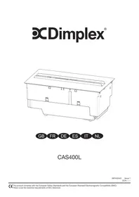
CASSETTE DIMPLEX 400 LED - LED DIMPLEX - Free user manual and instructions
Find the device manual for free CASSETTE DIMPLEX 400 LED DIMPLEX in PDF.



| Product type | Built-in electric fireplace with Opti-myst flame effect |
| Brand | Dimplex |
| Model | DIMPLEX CASSETTE 400 LED |
| Recessed dimensions (W x H x D) | 390 x 205 x 170 mm |
| Power supply | 220-240 V ~ 50 Hz |
| Flame effect | Opti-myst technology with water vapor and LED lighting |
| Water tank | Removable, manual filling with filtered water |
| Remote control | Included with 2 AA batteries, LCD screen |
| Flame adjustment | 6 levels (F1 to F6) |
| Programmable timer | Up to 4 periods per day, adjustable per day |
| Maximum temperature | 30 °C (adjustable, also in °F) |
| Safety | Grounding, automatic shutdown in case of overload |
| Maintenance | Bi-weekly cleaning of tank, tray and air filter |
| Air filter | Washable with water, clean regularly |
| Ventilation required | Cavity of at least 100 cm² for air circulation |
| Warranty | 2 years from date of purchase (excluding bulbs) |
Frequently Asked Questions - CASSETTE DIMPLEX 400 LED DIMPLEX
User questions about CASSETTE DIMPLEX 400 LED DIMPLEX
0 question about this device. Answer the ones you know or ask your own.
Ask a new question about this device
Download the instructions for your LED in PDF format for free! Find your manual CASSETTE DIMPLEX 400 LED - DIMPLEX and take your electronic device back in hand. On this page are published all the documents necessary for the use of your device. CASSETTE DIMPLEX 400 LED by DIMPLEX.
USER MANUAL CASSETTE DIMPLEX 400 LED DIMPLEX
Thank you for choosing this Dimplex electric fire. Please read this information guide carefully to be able to safely install, use and maintain your product.
Important Safety Advice
When using electrical appliances, basic precautions should always be followed to reduce the risk of fire, electrical shock and injury to persons, including the following:
1. WARNING
Do not place material or garments on, or obstruct the air circulation around the appliance. This appliance carries a DO NOT COVER warning
2. DAMAGE
Do not use this appliance if it has been dropped
If the appliance is damaged, check with the supplier before installation and operation.
If the supply cord is damaged it must be replaced by the manufacturer or service agent or a similarly qualified person in order to avoid a hazard.
3. LOCATION
Do not use outdoors.
Do not use in the immediate surroundings of a bath, shower or swimming pool.
Do not locate the fire immediately below a fixed socket outlet or connection box.
Ensure that furniture, curtains or other combustible material are positioned no closer than 1 metre from the appliance.
Use this appliance on a horizontal and stable surface, or fix it to a wall, if applicable.
4. PLUG POSITIONING
The appliance must be positioned so that the plug or point of isolation is accessible.
Keep the supply cord away from the front of the appliance.
5. UNPLUGGING
In the event of a fault unplug or isolate the device.
Unplug or isolate the device when not required for long periods.
6. OWNER/USER
This appliance can be used by children aged from 8 years and above and persons with reduced physical, sensory or mental capabilities or lack of experience and knowledge if they have been given supervision or instruction concerning use of the appliance in a safe way and understand the hazards involved. Children shall not play with the appliance. Cleaning and user maintenance shall not be made by Children without supervision.
Children of less than 3 years should be kept away unless continuously supervised. Children aged from 3 years and less than 8 years shall only switch on/off the appliance provided that it has been placed or installed in its intended normal operating position and they have been given supervision or instruction concerning use of the appliance in a safe way and understanding the hazards involved. Children aged from 3 years and less than 8 years shall not plug in, regulate and clean the appliance or perform user maintenance.
7. ELECTRICITY
WARNING - THIS APPLIANCE MUST BE EARTHED.
This appliance must be used on an AC ~ supply only and the voltage marked on the appliance must correspond to the supply voltage. Before switching on, please read the safety advice and operating instructions.
CAUTION — Some parts of this product can become very hot and cause burns. Particular attention
has to be given where children and vulnerable people are present.
WARNING - In order to avoid overheating, do not cover the appliance
General Information
Only use filtered water in this appliance.
Always ensure that the appliance is sitting on a level surface.
Please note: Used in an environment where background noise is very low, it may be possible to hear a sound which is related to the operation of the flame effect. This is normal and should not be a cause for concern.
If this product experiences a power surge for whatever reason the product may cut-out. This is a normal safety feature and the product will resume operation after 30 seconds.
Once installed, never move this appliance or lay on its back, without draining the water from sump and water tank.
If you intend not using the appliance for longer than 2 weeks, drain the water from sump and water tank and dry the sump.
The water tank, sump, sump lid, tank cap and air filters must be cleaned once every two weeks, particularly in hard water areas.
The sump and the water tank in this product are treated with a biocidal product, Silver Biocide. This conforms with the latest relevant ISO standard
Installation Instructions
BEFORE YOU START
- Ensure that all packing items are removed (read any warning labels carefully) and retain all packing for possible future use e.g. in the event of moving house or returning the appliance to your supplier.
- Before connecting to the mains supply, check that the supply voltage is the same as that stated on the appliance.
INSTALLATION
This appliance has been designed to be housed in separately designed structures – e.g. furniture, fireplace surrounds etc.
To incorporate this appliance into another structure, it should be securely fitted, following these guidelines:
ESSENTIAL VENTING
A suitable air vent is essential to ensure that air can circulate into the appliance - otherwise the Opti-myst flame effect will not operate correctly. A cavity of at least 100cm^2 is required for this air vent. This pathway for air must not be obstructed. For examples of air vents see (Fig 10) The air vent should be free from drafts.
- Construct an opening for the appliance LxWxH 390x205x170mm (+3-0mm)
- Ensure that there is sufficient room to thread through the mains cable
- A cavity of at least 100cm^2 is required to ensure air can circulate into the appliance. - See ESSENTIAL VENTING.
- Lower the appliance into the opening.
- Remove the water sump, to enable access to the screw holes.
- Screw the appliance into the structure by using suitable screws, not supplied.
Filling the Water Tank
- Place Water Tank in sink and remove cap (turn anti-clockwise to open)
- Fill Water Tank with filtered tap water only. This is necessary to prolong the life of the flame and smoke effect producing unit. The water should be filtered through a conventional domestic water filter unit and the filter should be replaced regularly. Distilled water must not be used.
- Screw the cap back on - do not overtighten.
- Place the Water Tank in the Sump, with the tank cap facing down and the flat side of the tank facing outward
- Place the Fuelbed on top of the Water Tank
Connect the power cable to the appropriate power connector at the back of the appliance and Plug the power cable into a 13amp/240volt outlet. The appliance is now ready for use.
This section describes how to activate your fire using either the manual controls or remote control.
MANUAL CONTROLS
The manual controls are located beneath the fuelbed
(See Fig.4 for Manual Control lay out)
Switch 'A':- Controls the electricity supply to the Fire.
Note: This switch must be in the 'ON' ( I ) position for the Fire to operate.
Switch 'B':- Press to turn on the flame effect. This will be indicated by an audible beep. Although the main lights operate immediately it will take a further 30 seconds before the flame effect starts.
Press to put fire in to standby mode. This will be indicated by one beep.
The remote control is packed with 2 AA batteries in a bag. Lift off the battery cover on the back of the remote control and insert the batteries taking note of the polarity.
The remote control has already been paired to your product during factory assembly. In the unlikely event that the remote control disconnects from the product, or you obtain a spare remote control, you will need to complete the pairing process:
- With the product plugged in press switch A to the ON (I) position. You should hear an audible beep
- Press and hold 'Button 6' until PAIR appears on the display
- Bring the remote control close to the product where the receiver is _0^ . See Fig 4
- The product will start to beep and blink
- Press 'Button 6' to complete the pairing process. The product will go into standby mode.
Switching on the appliance
Press and hold the ENTER button for 3 seconds to activate the remote control. FIRE will be displayed and ON will be blinking. Press ENTER to swtch on the appliance. To turn off the appliance press MENU so that FIRE is blinking, press ENTER twice.
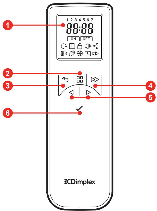
1 Display Screen
2 'Menu' Button
3 'Back' Button
4 'Advance' Button
5 'Up and Down' Arrows
6 'Enter' Button
Adjust the Flame Setting
With the remote control activated press once . FIRE will be blinking on the display. Press ENTER. The current flame setting will be displayed F1-F6. Press the and buttons to adjust the setting. After you have selected your flame setting press BACK twice to exit the menu and return to the home screen.
Setting the Date and Time
To set the date and time on the heater;
- Press the Menu button
- Press button 4 times
- Press Enter when the Date & Time icon is blinking
- Press Enter to set Time
- Press and to set the Hour, press Enter
- Press and to set the Minutes, press Enter to confirm the time
- Press and to set the Day, press Enter
- Press and to set the Month, press Enter
- Press and to set the Year, press Enter to confirm the date

User Timer - To re-programme the factory default Timer Modes:
- Press Menu Button
- Press once to the schedule Icon is blinking. Press Enter
- Press Twice then press Enter
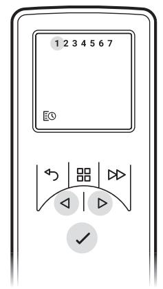
Days of the weeks are now displayed at the top of the screen
Day 1 = Monday
Day 2 = Tuesday
Day 3 = Wednesday
Day 4 = Thursday
Day 5 = Friday
Day 6 = Saturday
Day 7 = Sunday
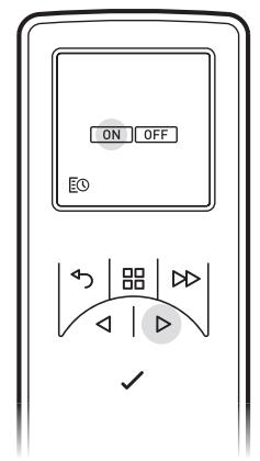
- Press Enter to Modify Day 1 or Press to navigate to the desired day and Press Enter to Select
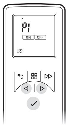
- P1 will be displayed on screen
- Press Enter to select P1, to navigate to P2, P3 or P4 press and press Enter to select
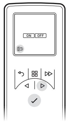
- ON will be highlighted, press Enter to set the on Time
- Press or to adjust the on Hour time, press Enter to Confirm
- Press or to adjust the on Minute time, press Enter to Confirm
- Press or to adjust the Temperature setting, press Enter to Confirm
- Press or to adjust the off Hour time, press Enter to Confirm
- Press or to adjust the off Minute time, press Enter to Confirm
Press Enter to modify Programme P2, follow steps 5-12, Press to skip to P3
Press Enter to modify Programme P3, follow steps 5-12, Press to Skip to P4
Press Enter to modify Programme P4, follow steps 5-12
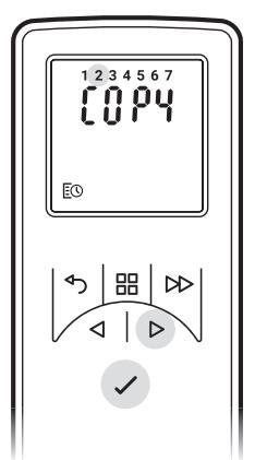
To copy newly programmed P1-P4 heating programmes to other days press the Enter button.
Copy will be displayed on screen
To copy to the next day in sequence, press button. To deselect the next day in sequence press
Enter button.
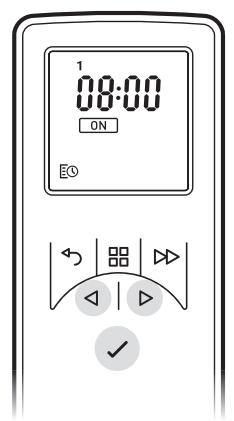
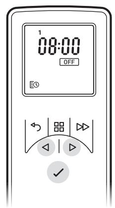
The days of the week that are selected will be displayed at the top of the screen. The days that have been deselected will not be visible (see Diagrams).
Press Enter to confirm, backlight will flash and return to home screen.
Getting the Desired Flame Effect
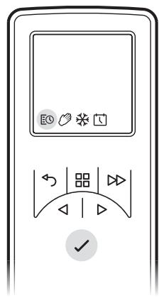
- Using the remote control press MENU, FIRE on the display will be flashing, press ENTER. The current setting will be displayed. Press ^ or v to toggle between F1 and F6. F1 being the lowest setting and F6 being the highest setting.
- Generally the flames appear more realistic when the flame control is turned down.
- Give the flame generator time to react to changes you may make.
- The fire will use less water if the flame effect is set to a lower level.
- Do not tilt or move the fire while there is water in the tank or sump.
- Make sure that the fire is on a level floor.
Customising the display
The maximum temperature set point on the product is 30^ You have the option to reduce this set point. You can also change ^ C to ^ F
- Press the Menu button.
- Press the ADV button twice - SP will be blinking.
- Press Enter to confirm.
- Press v or ^ to choose between °C and °F.
- Press Enter to confirm.
- Press v or ^ to choose your maximum temperature set point.
- Press Enter to confirm.
- Press BACK three times to return to the home screen.
Maintenance
GENERAL TIPS
Only use filtered tap water in this appliance.
Always ensure that the appliance is sitting on a level surface.
If you intend not using the appliance for longer than 2 weeks, remove and empty the sump and water tank.
Once installed, never move this appliance or lay on its back, without draining the water from sump and water tank.
FILLING THE WATER TANK
When the water tank is empty, the flame and smoke effect shuts off and you will hear 2 audible beeps, follow these steps.
- Press Switch 'A' to (0) (See Fig.4)
- Gently lift out the fuelbed and carefully set aside.
- Remove the water tank by lifting upwards and outwards.
- Place the water tank in sink and remove cap, Anti-clockwise to open.
- Fill tank with filtered tap water only. This is necessary to prolong the life of the flame and smoke producing unit. The water should be filtered through a conventional domestic water filter unit and the filter should be replaced regularly.
- Screw the cap back on, do not over tighten.
- Return the tank to the sump, with the tank cap facing down
- Gently place the fuelbed back into position.
- Press Switch 'A' to 'ON' (I) position (See Fig.4)
CLEANING
Warning - Always press Switch 'A' to the 'OFF' (0) position (See Fig.4) and disconnect from the power supply before cleaning the fire.
We recommend cleaning the following components once every 2 weeks, particularly in hard water areas:-
Water Tank, Sump, Nozzle, Tank cap and seal, Air filter.
For general cleaning use a soft clean duster – never use abrasive cleaners.
To remove any accumulation of dust or fluff, the soft brush attachment of a vacuum cleaner should occasionally be used.
Water tank
- Remove water tank, as described earlier, put into sink and empty water.
- Using the supplied brush gently rub the inside surfaces of the cap paying particular attention to the rubber ring in the outer groove and the centre rubber seal.
- Put a small quantity of washing up liquid into the tank, refit the cap and shake well, rinse out until all traces of washing up liquid are gone.
- Refill with filtered tap water only, replace the cap, do not overtighten.
Sump
- Gently lift out the fuelbed and place carefully on the ground.
- Press Switch 'A' to the 'OFF' (0) position
- Remove the water tank by lifting upwards.
- Disconnect the electrical connector, located on the back of the product under the rating label. (See Fig.5).
- Pinch open the red clips.
- Gently lift up the orange nozzle and set aside.
- Lift out the sump being careful not to spill any water left inside it.
- The transducer is secured in the sump by a small clip. Pull back the clip to allow the transducer to be removed from the sump. Carefully tilt, so that the liquid drains out of the sump.
- Put a small amount of washing up liquid into the sump, and using the supplied brush, gently clean all surfaces in the sump and gently clean the transducer including the metal discs located in the top grooved surface. (See Fig.7)
- When cleaned, thoroughly rinse the sump with clean water to remove all traces of washing up liquid.
- Clean the Nozzle with the brush and flush out thoroughly with water. (See Fig.8)
- Reverse the above steps to reassemble.
Air filter
- Gently lift out the fuelbed and place carefully on the ground.
- Gently slide the air filter upwards out of its plastic holder. (See Fig.9)
- Gently rinse with water in the sink and dry with fabric towel before returning.
- Replace the filter making sure that the coarse black filter is facing the front of the fire.
- Replace the fuelbed.
Additional Information
AFTER SALES SERVICE
Your product is guaranteed for two years from the date of purchase. Within this period, we undertake to repair or exchange this product free of charge (excluding lamps & subject to availability) provided it has been installed and operated in accordance with these instructions. Your rights under this guarantee are additional to your statutory rights, which in turn are not affected by this guarantee.
PATENT / PATENT APPLICATION
Products within the Optimyst range are protected by one or more of the following patents and patent applications: Great Britain GB 2402206, GB 2460259, GB 2460453, GB 2418014, GB 2465738, GB 2449925, GB 2465537, GB 2455277, GB1020534.2, GB1020537.5, GB1110987.3 United States US 7967690, US 2010299980, US 2011062250, US 2008028648, US 13/167,042 Russia RU2008140317 European EP 2029941, EP 2201301, EP 2315976, EP 1787063, EP07723217.1, EP11170434.2, EP 11170435.9 China CN 101883953, CN 200980128666.2, CN 101057105, CN 101438104 Australia AU 2009248743, AU 2007224634 Canada CA 2725214, CA 2579444, CA 2645939 International Patent Application WO 2006027272 South Africa ZA 200808702 Mexico MX 2008011712 Korea KR 20080113235 Japan JP 2009529649 Brazil BR P10708894-9 India IN 4122/KOLNP/2008 New Zealand NZ 571900
Troubleshooting
| Symptom | Cause | Corrective Action |
| The flame effect will not start. | Mains plug is not plugged in. | Check plug is connected to wall socket correctly. |
| Low water level. | Check that the water tank is full and there is water in the sump. | |
| Low voltage connector not connected properly. (See Fig.5) | Check that the connector is inserted correctly. (See Fig.5) | |
| The Transducer Unit is not sitting correctly in the sump | Ensure the Transducer in sitting down into the moulded recess in the sump | |
| The flame effect is too low. | The Metal Disc in the transducer might be dirty (See Fig.7) | Clean the Metal Disc with soft brush supplied. (See Fig.7) See ‘Maintenance.’ for a step by step procedure. |
| The wire from the Transducer Unit is sitting over the metal disc | Direct the wire to the back of the sump and make sure it sits into the side slot exiting the sump. | |
| The air filter may need cleaning | Remove air filter and clean it. | |
| The air filter may be positioned incorrectly | Reposition air filter | |
| Unpleasant smell when unit is used. | Dirty or stale water. | Clean the unit as described under maintenance. |
| Using unfiltered tap water. | Use only filtered tap water. | |
| Main lamps are not working and there are no flames or smoke. | There is no water in the water tank | Follow instructions under Maintenance, ‘Filling the water tank’. Check the plug is connected to the wall socket correctly and that Switch ‘A’ Fig. 4 is in the ‘ON’ (I) position. |
Introduction
Mexico MX 2008011712
Korea KR 20080113235
Japan JP 2009529649
Brasilien BR P10708894-9
Indien IN 4122/KOLNP/2008
Australia AU 2009248743, AU 2007224634
Caná CA 2725214, CA 2579444, CA 2645939
Mexico MX 2008011712
Corea KR 20080113235
Japon JP 2009529649
Brasil BR P10708894-9
India IN 4122/KOLNP/2008
Australia AU 2009248743, AU 2007224634
Canada CA 2725214, CA 2579444, CA 2645939
WAARSCHUWING - DIT TOETSTEL MOET WORDEN GEAARD.
Mexico MX 2008011712
Korea KR 20080113235
Japan JP 2009529649
Brazilié BR P10708894-9
Indie IN 4122/KOLNP/2008
- Important Safety Advice
- WARNING
- DAMAGE
- LOCATION
- PLUG POSITIONING
- UNPLUGGING
- OWNER/USER
- ELECTRICITY
- General Information
- Installation Instructions
- BEFORE YOU START
- INSTALLATION
- ESSENTIAL VENTING
- Filling the Water Tank
- MANUAL CONTROLS
- Switching on the appliance
- Adjust the Flame Setting
- Setting the Date and Time
- Getting the Desired Flame Effect
- Customising the display
- Maintenance
- GENERAL TIPS
- CLEANING
- Water tank
- Sump
- Air filter
- Additional Information
- AFTER SALES SERVICE
- PATENT / PATENT APPLICATION
- Introduction
Brand : DIMPLEX
Model : CASSETTE DIMPLEX 400 LED
Category : LED