PAC1800 - Air Conditioning DARTY - Free user manual and instructions
Find the device manual for free PAC1800 DARTY in PDF.

| Brand | Darty |
| Model | PAC1800 |
| Product type | Monobloc portable air conditioner |
| Energy efficiency class | A |
| Nominal cooling capacity | 2.0 kW |
| Nominal power input (cooling) | 0.8 kW |
| EER (energy efficiency ratio) | 2.6 |
| Hourly consumption (cooling) | 0.8 kWh/h |
| Sound power level | 62 dB(A) |
| Refrigerant | R290 (0.14 kg) |
| Global warming potential (GWP) | 3 |
| Power supply | 220-240 V ~50 Hz |
| Fuse | 3.15 A, 250 V, type 4T |
| Remote control batteries | 2 x AAA 1.5 V |
| Operating modes | Cooling, Fan, Dehumidification |
| Special functions | Timer (on/off), Sleep, Auto restart, Shortcut |
| Temperature range (cooling mode) | 17 °C to 30 °C |
| Fan speeds | Low, High, Auto |
| Minimum room area | 8 m² |
| Clearance around the appliance | 50 cm from obstacles, 30 cm from walls |
| Wall hole diameter for exhaust | 125 mm |
| Filter maintenance | Clean every 2 weeks |
| Important safety instructions | Use on flat floor, do not block grilles, unplug before cleaning, do not use extension cord |
| Repairability | Reserved for qualified professional (sealed refrigerant circuit) |
| Disposal | Do not dispose with household waste, take to recycling center |
Frequently Asked Questions - PAC1800 DARTY
User questions about PAC1800 DARTY
0 question about this device. Answer the ones you know or ask your own.
Ask a new question about this device
Download the instructions for your Air Conditioning in PDF format for free! Find your manual PAC1800 - DARTY and take your electronic device back in hand. On this page are published all the documents necessary for the use of your device. PAC1800 by DARTY.
USER MANUAL PAC1800 DARTY
PLEASE READ THE FOLLOWING SAFETY WARNINGS AND THE INSTRUCTIONS CAREFULLY BEFORE USING THE APPLIANCE AND KEEP FOR FUTURE REFERENCE.
EN
Warnings
- This appliance is intended for domestic household use only and should not be used for any other purpose or in any other application, such as for non-domestic use or in a commercial environment.
- If the supply cord is damaged, it must be replaced by the manufacturer, its service agent or similarly qualified persons in order to avoid a hazard.
- This appliance can be used by children aged from 8 years and above and persons with reduced physical, sensory or mental capabilities or lack of experience and knowledge if they have been given supervision or instruction concerning use of the appliance in a safe way and understand the hazards involved.
Children shall not play with the appliance.
Cleaning and user maintenance shall not be made by children without supervision.
- Regarding the details concerning the method and frequency of cleaning, please see section "CLEANING AND MAINTENANCE" on pages 31-32.
Read the instructions.
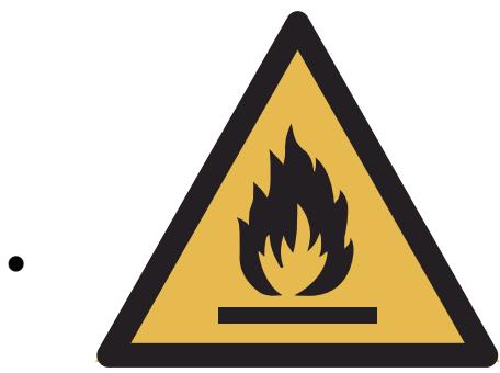
Warning; Risk of fire/Flammable materials
Operator's manual; operating instructions
- The appliance shall be installed in accordance with national wiring regulations.
- This product contains non-fluorinated greenhouse gas (hermetically sealed) which is dangerous for the environment and contributes to global warming if released to the atmosphere.
Refrigerant type: R290 Global warming potential (GWP): 3
- This product contains a refrigerant fluid with a GWP equal to 3. This means that if 1kg of this refrigerant fluid would be leaked to the atmosphere, the impact on global warming would be 3 times higher than 1kg of CO_2 , over a period of 100 years. Never try to interfere with the refrigerant circuit yourself or disassemble the product yourself and always ask a professional.
- Refrigerant leakage contributes to climate change.
Refrigerant with lower global warming potential (GWP) would contribute less to global warming than a refrigerant with higher GWP, if leaked to the atmosphere.
For disposal of the appliance:
To prevent possible harm to the environment or human health from uncontrolled waste disposal, recycle the appliance responsibly to promote the sustainable reuse of material resources, the refrigerants and the flammable insulation blowing gases. The disposal should only be done through public collection points; contact the waste treatment centre nearest your home for more details on the correct procedures for disposal.
For installation, servicing:
The appliance should be placed on a horizontal floor and keep the ventilation freely. Don't try to replace or repair any components by yourself, ask the service agency for help if necessary.
For handling:
Always handle the appliance to avoid any damage.
- The battery must be removed from the appliance before it is scrapped.
- The battery is to be disposed of safely.
- Batteries are to be inserted with the correct polarity.
- Different types of batteries or new and used batteries are not to be mixed.
- Batteries of the same or equivalent type as recommended are to be used.
- Exhausted batteries are to be removed from the product.
- The supply terminals are not to be short-circuited.
- Attention should be drawn to the environmental aspects of battery disposal. Don't throw used batteries in dustbin. Please contact your retailer in order to protect the environment.
- The batteries (batteries installed) shall not be exposed to excessive heat such as sunshine, fire or the like.
- If battery leakage occurs, avoid contact with skin. Isolate the leaking battery in a sealed plastic bag and put it in the scrap following the instructions environmental protection. If contact with the skin, mucous membranes or eyes, rinse thoroughly with water and contact your doctor or ophthalmologist.
- Do not recharge non-rechargeable batteries because of the risk of explosion.
- Rechargeable batteries are to be removed from the appliance before being charged.
Safety Precautions
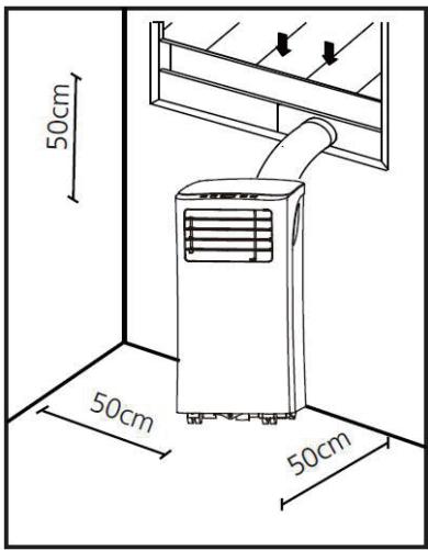
- Only use the appliance in the upright position on a flat level surface and at least 50~cm from the wall or any objects.
- Installation must be performed according to the installation instructions. Improper installation can cause water leakage, electrical shock, or fire.
- Use only the included accessories and parts, and specified tools for the installation. Using non-standard parts can cause water leakage, electrical shock, fire, and injury or property damage.
- Make sure that the outlet you are using is grounded and has the appropriate voltage.
- Your appliance must be used in a properly grounded wall receptacle. If the wall receptacle you intend to use is not adequately grounded or protected by a time delay fuse or circuit breaker (the fuse or circuit breaker needed is determined by the maximum current of the unit. The maximum current is indicated on the nameplate located on unit), have a qualified electrician install the proper receptacle.
- Install the appliance on a flat, sturdy surface. Failure to do so could result in damage or excessive noise and vibration.
- The appliance must be kept free from obstruction to ensure proper function and to mitigate safety hazards.
- Do not modify the length of the power cord or use an extension cord to power the appliance.
- Do not share a single outlet with other electrical appliances. Improper power supply can cause fire or electrical shock.
- Do not install your air conditioner in a wet room such as a bathroom or laundry room. Too much exposure to water can cause electrical components to short circuit.
- Do not install the appliance in a location that may be exposed to combustible gas, as this could cause fire.
- The appliance has wheels to facilitate moving. Make sure not to use the wheels on thick carpet or to roll over objects, as these could cause tipping.
- Do not operate the appliance if it has been damaged.
- Do not touch the unit with wet or damp hands or when barefoot.
- If the air conditioner is knocked over during use, turn off and unplug it from the mains socket immediately. Visually inspect the appliance to ensure there is no damage.
- In a thunderstorm, the power must be cut off to avoid damage to the appliance due to lightning.
- Your air conditioner should be used in such a way that it is protected from moisture. e.g. condensation, splashed water, etc. Do not place or store your air conditioner
EN
where it can fall or be pulled into water or any other liquid. Unplug immediately if it occurs.
- Turn off and unplug the appliance from the mains socket when not in use or before cleaning. Allow the appliance to cool before cleaning.
- Do not let the cord hang over the edge of a table or counter, touch hot surfaces, or become knotted.
- Do not run cord under carpeting. Do not cover cord with throw rugs, runners, or similar coverings. Do not route cord under furniture or appliances. Arrange cord away from traffic area and where it will not be tripped over.
- Do not remove any fixed covers. Never use this appliance if it is not working properly, or if it has been dropped or damaged.
- To protect against a fire, electric shock or personal injury, do not immerse cord, electric plugs or appliance in water or other liquids.
- Do not use the appliance outdoors.
- Do not leave the appliance unattended when in use.
- Do not cover or obstruct the inlet or outlet grilles.
- Do not use the appliance for functions other than those described in this instruction manual.
- Disconnect the power if strange sounds, smell, or smoke comes from the appliance.
- Do not press the buttons on the control panel with anything other than your fingers.
- Do not operate or stop the appliance by inserting or pulling out the power cord plug.
- Do not use hazardous chemicals to clean or come into contact with the appliance.
- Do not use the appliance in the presence of inflammable substances or vapour such as alcohol, insecticides, petrol, etc.
- Always transport your air conditioner in a vertical position and stand on a stable, level surface during use.
Battery handling and usage
Remote control batteries (included):
- The batteries should only be replaced by adults. Do not allow children to use the remote control unless the battery cover is attached.
- Replace the battery only with the same type. The batteries used in the remote control are two AAA 1.5V batteries which are accessible and can
EN
SERVICE OPERATIONS
WARNING
Do not use means to accelerate the defrosting process or to clean, other than those recommended by the manufacturer.
The appliance shall be stored in a room without continuously operating ignition sources (for example: open flames, an operating gas appliance or an operating electric heater.
Do not pierce or burn.
Be aware that refrigerants may not contain an odour.
Appliance shall be installed, operated and stored in a room with a floor area larger than 8m^2 .
Installation (Space)
The installation of pipe-work shall be kept to a minimum;
Pipe-work shall be protected from physical damage and shall not be installed in an unventilated space;
Compliance with national gas regulations shall be observed;
- Mechanical connections shall be accessible for maintenance purposes;
Minimum floor area of the room: 8m^2
Maximum refrigerant charge amount (M): 0,14kg
- keep ventilation openings clear of obstruction;
Servicing shall be performed only as recommended by the manufacturer.
An unventilated area where the appliance using flammable refrigerants is installed shall be so constructed that should any refrigerant leak, it will not stagnate so as to create a fire or explosion hazard. This shall include:
- The appliance shall be stored in a well-ventilated area where the room size corresponds to the room area as specified for operation.
- The appliance shall be stored in a room without continuously operating open flames (for example an operating gas appliance) and ignition sources (for example an operating electric heater).
The appliance shall be stored so as to prevent mechanical damage from occurring.
Specific information about the credentials of qualified service personnel:
- Any person who is involved with working on or breaking into a refrigerant circuit should hold a current valid certificate from an industry-accredited assessment authority, which authorises their competence to handle refrigerants safely in accordance with an industry recognised assessment specification.
Servicing shall only be performed as recommended by the equipment manufacturer. Maintenance and repair requiring the assistance of other skilled personnel shall be carried out under the supervision of the person competent in the use of flammable refrigerants.
Information on servicing
1. Checks to the area
Prior to beginning work on systems containing flammable refrigerants, safety checks are necessary to ensure that the risk of ignition is minimised. For repair to the refrigerating system, the following precautions shall be complied with prior to conducting work on the system.
2. Work procedure
Work shall be undertaken under a controlled procedure so as to minimise the risk of a flammable gas or vapour being present while the work is being performed.
EN
3. General work area
All maintenance staff and others working in the local area shall be instructed on the nature of work being carried out. Work in confined spaces shall be avoided. The area around the workspace shall be sectioned off. Ensure that the conditions within the area have been made safe by control of flammable material.
4. Checking for presence of refrigerant
The area shall be checked with an appropriate refrigerant detector prior to and during work, to ensure the technician is aware of potentially flammable atmospheres. Ensure that the leak detection equipment being used is suitable for use with flammable refrigerants, i.e. non-sparking, adequately sealed or intrinsically safe.
5. Presence of fire extinguisher
If any hot work is to be conducted on the refrigeration equipment or any associated parts, appropriate fire extinguishing equipment shall be available to hand. Have a dry powder or CO_2 fire extinguisher adjacent to the charging area.
6. No ignition sources
No person carrying out work in relation to a refrigeration system which involves exposing any pipe work that contains or has contained flammable refrigerant shall use any sources of ignition in such a manner that it may lead to the risk of fire or explosion. All possible ignition sources, including cigarette smoking, should be kept sufficiently far away from the site of installation, repairing, removing and disposal, during which flammable refrigerant can possibly be released to the surrounding space. Prior to work taking place, the area around the equipment is to be surveyed to make sure that there are no flammable hazards or ignition risks. "No Smoking" signs shall be displayed.
7. Ventilated area
Ensure that the area is in the open or that it is adequately ventilated before breaking into the system or conducting any hot work. A degree of ventilation shall continue during the period that the work is carried out. The ventilation should safely disperse any released refrigerant and preferably expel it externally into the
EN
atmosphere.
8. Checks to the refrigeration equipment
Where electrical components are being changed, they shall be fit for the purpose and to the correct specification. At all times the manufacturer's maintenance and service guidelines shall be followed. If in doubt consult the manufacturer's technical department for assistance.

The following checks shall be applied to installations using flammable refrigerants:
- the charge size is in accordance with the room size within which the refrigerant containing parts are installed;
- the ventilation machinery and outlets are operating adequately and are not obstructed;
- if an indirect refrigerating circuit is being used, the secondary circuit shall be checked for the presence of refrigerant;
marking to the equipment continues to be visible and legible. Markings and signs that are illegible shall be corrected; - refrigeration pipe or components are installed in a position where they are unlikely to be exposed to any substance which may corrode refrigerant containing components, unless the components are constructed of materials which are inherently resistant to being corroded or are suitably protected against being so corroded.
9. Checks to electrical devices
Repair and maintenance to electrical components shall include initial safety checks and component inspection procedures. If a fault exists that could compromise safety, then no electrical supply shall be connected to the circuit until it is satisfactorily dealt with. If the fault cannot be corrected immediately but it is necessary to continue operation, an adequate temporary solution shall be used. This shall be reported to the owner of the equipment so all parties are advised.
Initial safety checks shall include:
that capacitors are discharged: this shall be done in a safe manner to avoid possibility of sparking;
that no live electrical components and wiring are exposed while charging, recovering or purging the system;
that there is continuity of earth bonding.
Repairs to sealed components
- During repairs to sealed components, all electrical supplies shall be disconnected from the equipment being worked upon prior to any removal of sealed covers, etc. If it is absolutely necessary to have an electrical supply to equipment during servicing, then a permanently operating form of leak detection shall be located at the most critical point to warn of a potentially hazardous situation.
- Particular attention shall be paid to the following to ensure that by working on electrical components, the casing is not altered in such a way that the level of protection is affected. This shall include damage to cables, excessive number of connections, terminals not made to original specification, damage to seals, incorrect fitting of glands, etc.
Ensure that apparatus is mounted securely.
Ensure that seals or sealing materials have not degraded such that they no longer serve the purpose of preventing the ingress of flammable atmospheres.
Replacement parts shall be in accordance with the manufacturer's specifications.
NOTE The use of silicon sealant may inhibit the effectiveness of some types of leak detection equipment. Intrinsically safe components do not have to be isolated prior to working on them.
Repair to intrinsically safe components
Do not apply any permanent inductive or capacitance loads to the circuit without ensuring that this will not exceed the permissible voltage and current permitted for the equipment in use.
Intrinsically safe components are the only types that can be worked on while live in the presence of a flammable atmosphere. The test apparatus shall be at the correct rating.
Replace components only with parts specified by the manufacturer. Other parts may result in the ignition of refrigerant in the atmosphere from a leak.

Cabling
Check that cabling will not be subject to wear, corrosion, excessive pressure, vibration, sharp edges or any other adverse environmental effects. The check shall also take into account the effects of ageing or continual vibration from sources such as compressors or fans.
Detection of flammable refrigerants
Under no circumstances shall potential sources of ignition be used in the searching for or detection of refrigerant leaks. A halide torch (or any other detector using a naked flame) shall not be used.
Leak detection methods
The following leak detection methods are deemed acceptable for systems containing flammable refrigerants.
Electronic leak detectors shall be used to detect flammable refrigerants, but the sensitivity may not be adequate, or may need re-calibration. (Detection equipment shall be calibrated in a refrigerant-free area.) Ensure that the detector is not a potential source of ignition and is suitable for the refrigerant used. Leak detection equipment shall be set at a percentage of the LFL of the refrigerant and shall be calibrated to the refrigerant employed and the appropriate percentage of gas (25% maximum) is confirmed.
Leak detection fluids are suitable for use with most refrigerants but the use of detergents containing chlorine shall be avoided as the chlorine may react with the refrigerant and corrode the copper pipe-work.
If a leak is suspected, all naked flames shall be removed/extinguished.
If a leakage of refrigerant is found which requires brazing, all of the refrigerant shall be recovered from the system, or isolated (by means of shut off valves) in a part of the system remote from the leak. Oxygen free nitrogen (OFN) shall then be purged through the system both before and during the brazing process.
EN
Removal and evacuation
When breaking into the refrigerant circuit to make repairs – or for any other purpose – conventional procedures shall be used. However, it is important that best practice is followed since flammability is a consideration. The following procedure shall be adhered to:
remove refrigerant;
purge the circuit with inert gas;
evacuate;
purge again with inert gas;
open the circuit by cutting or brazing.
The refrigerant charge shall be recovered into the correct recovery cylinders. The system shall be "flushed" with OFN to render the unit safe. This process may need to be repeated several times. Compressed air or oxygen shall not be used for this task.
Flushing shall be achieved by breaking the vacuum in the system with OFN and continuing to fill until the working pressure is achieved, then venting to atmosphere, and finally pulling down to a vacuum. This process shall be repeated until no refrigerant is within the system. When the final OFN charge is used, the system shall be vented down to atmospheric pressure to enable work to take place. This operation is absolutely vital if brazing operations on the pipe-work are to take place.
Ensure that the outlet for the vacuum pump is not close to any ignition sources and there is ventilation available.
Charging procedures
In addition to conventional charging procedures, the following requirements shall be followed.
- Ensure that contamination of different refrigerants does not occur when using charging equipment. Hoses or lines shall be as short as possible to minimise the amount of refrigerant contained in them.
Cylinders shall be kept upright. - Ensure that the refrigeration system is earthed prior to charging the system with refrigerant.
Label the system when charging is complete (if not already).
Extreme care shall be taken not to overfill the refrigeration system.
Prior to recharging the system it shall be pressure tested with OFN. The system shall be leak tested on completion of charging but prior to commissioning. A follow up leak test shall be carried out prior to leaving the site.
Decommissioning
Before carrying out this procedure, it is essential that the technician is completely familiar with the equipment and all its detail. It is recommended good practice that all refrigerants are recovered safely. Prior to the task being carried out, an oil and refrigerant sample shall be taken in case analysis is required prior to re-use of reclaimed refrigerant. It is essential that electrical power is available before the task is commenced.
a) Become familiar with the equipment and its operation.
b) Isolate system electrically.
c) Before attempting the procedure ensure that:
mechanical handling equipment is available, if required, for handling refrigerant cylinders;
□ all personal protective equipment is available and being used correctly;
the recovery process is supervised at all times by a competent person;
□ recovery equipment and cylinders conform to the appropriate standards.
d) Pump down refrigerant system, if possible.
e) If a vacuum is not possible, make a manifold so that refrigerant can be removed
EN
from various parts of the system.
f) Make sure that cylinder is situated on the scales before recovery takes place.
g) Start the recovery machine and operate in accordance with manufacturer's instructions.
h) Do not overfill cylinders. (No more than 80% volume liquid charge).
i) Do not exceed the maximum working pressure of the cylinder, even temporarily.
j) When the cylinders have been filled correctly and the process completed, make sure that the cylinders and the equipment are removed from site promptly and all isolation valves on the equipment are closed off.
k) Recovered refrigerant shall not be charged into another refrigeration system unless it has been cleaned and checked.
Labelling
Equipment shall be labelled stating that it has been de-commissioned and emptied of refrigerant. The label shall be dated and signed. Ensure that there are labels on the equipment stating the equipment contains flammable refrigerant.
Recovery
When removing refrigerant from a system, either for servicing or decommissioning, it is recommended good practice that all refrigerants are removed safely.
When transferring refrigerant into cylinders, ensure that only appropriate refrigerant recovery cylinders are employed. Ensure that the correct number of cylinders for holding the total system charge are available. All cylinders to be used are designated for the recovered refrigerant and labelled for that refrigerant (i.e. special cylinders for the recovery of refrigerant). Cylinders shall be complete with pressure relief valve and associated shut-off valves in good working order. Empty recovery cylinders are evacuated and, if possible, cooled before recovery occurs.
The recovery equipment shall be in good working order with a set of instructions concerning the equipment that is at hand and shall be suitable for the recovery of flammable refrigerants. In addition, a set of calibrated weighing scales shall be

available and in good working order. Hoses shall be complete with leak-free disconnect couplings and in good condition. Before using the recovery machine, check that it is in satisfactory working order, has been properly maintained and that any associated electrical components are sealed to prevent ignition in the event of a refrigerant release. Consult manufacturer ifin doubt.
The recovered refrigerant shall be returned to the refrigerant supplier in the correct recovery cylinder, and the relevant Waste Transfer Note arranged. Do not mix refrigerants in recovery units and especially not in cylinders.
If compressors or compressor oils are to be removed, ensure that they have been evacuated to an acceptable level to make certain that flammable refrigerant does not remain within the lubricant. The evacuation process shall be carried out prior to returning the compressor to the suppliers. Only electric heating to the compressor body shall be employed to accelerate this process. When oil is drained from a system, it shall be carried out safely.
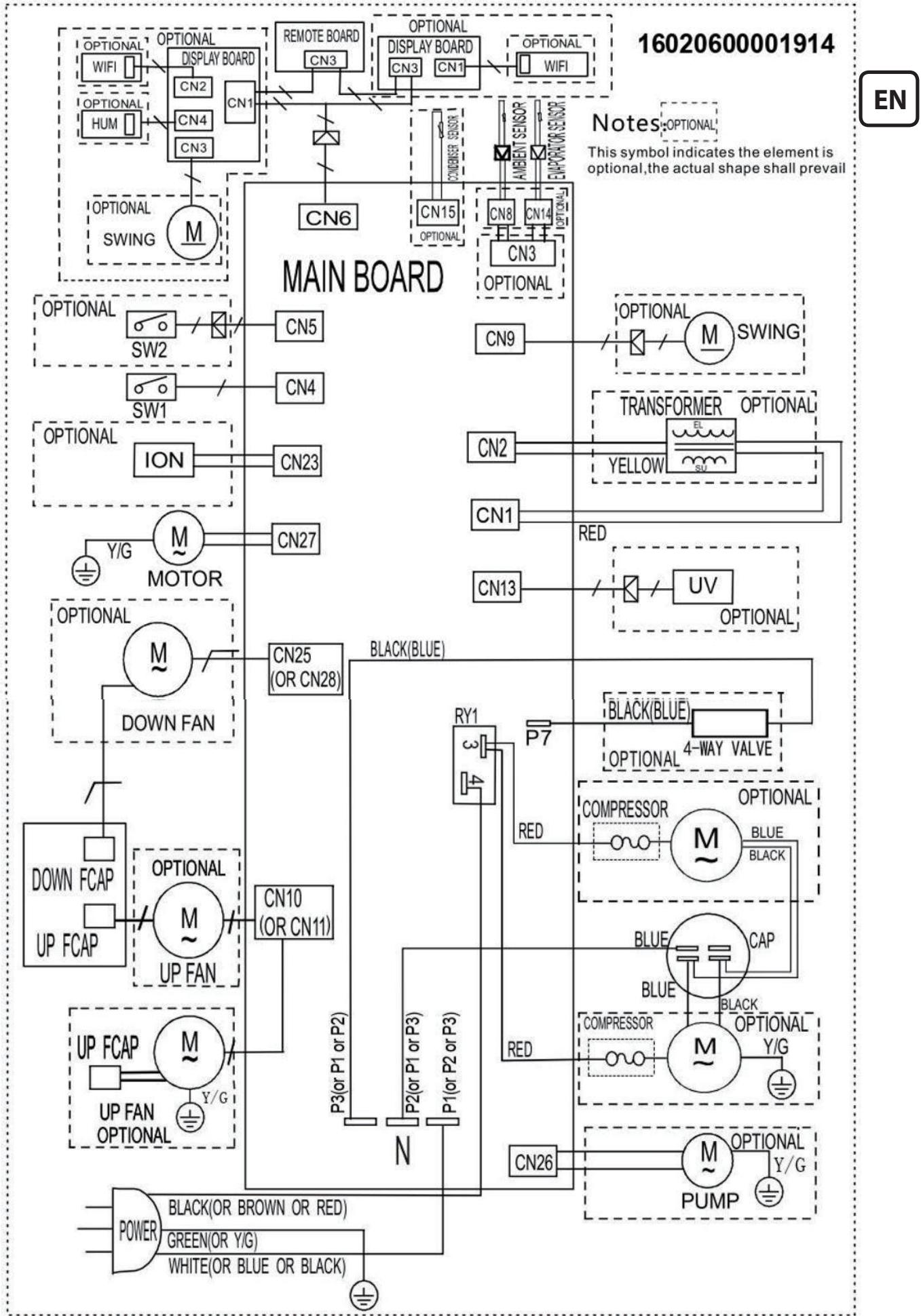
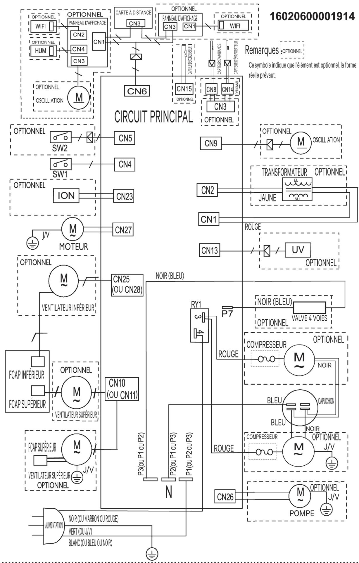
WIRING DIAGRAM
Fuse
Type: 4T, Voltage: 250V, Current:3.15A
Type: 334, Voltage: 250V, Current:3.15A

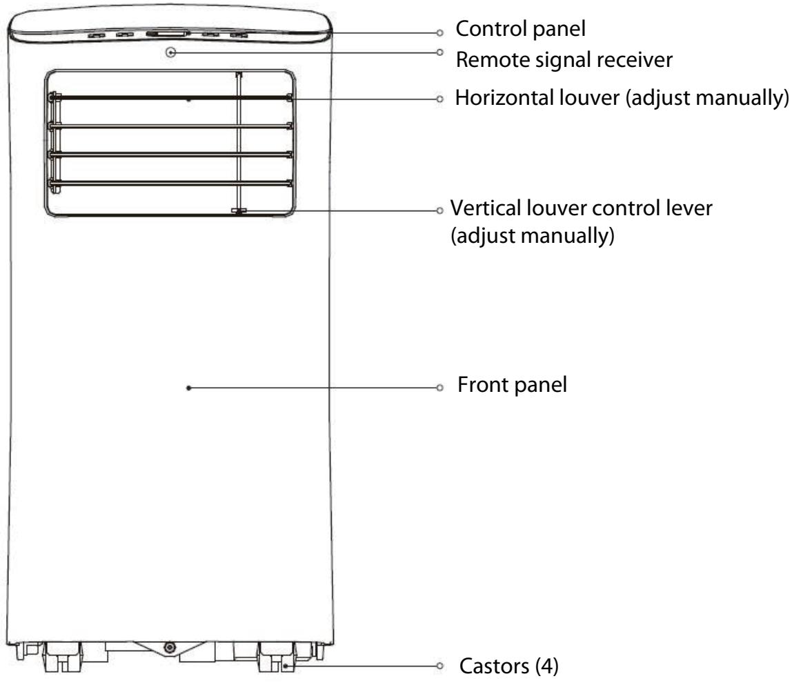
Front View

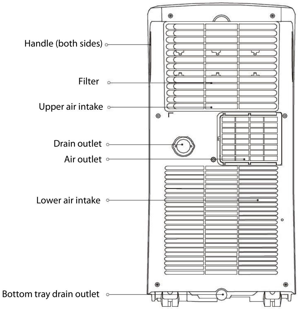
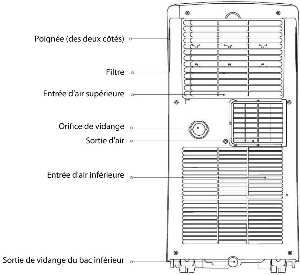
Rear View

Accessories
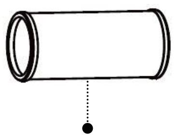
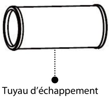
Exhaust hose
Exhaust connector


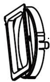
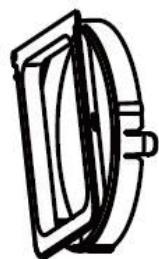
Wall exhaust adapter with cap
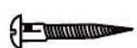
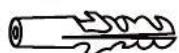
ew and anchor sets)
Drain hose
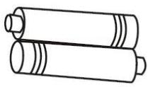

Remote control with batteries
INSTALLATION
Location
- The appliance should be placed on a firm floor to minimize noise and vibration.
- The appliance must be placed within reach of a properly rated grounded socket and the drain outlet (located on the back of the appliance) must be accessible.
- Never place any obstacles around the air inlet or outlet of the appliance.
- Allow at least 30cm of space from the wall with window for efficient air
conditioning. The horizontal louvers should be at least 50cm away from obstacles.
EN
Exhaust hose installation
The exhaust hose and connector must be installed or removed from the appliance in accordance with the way it is being used:
For cool mode : The exhaust hose and connector must be connected to the appliance.
For fan or dry mode : The exhaust hose and connector should be disconnected from the appliance.
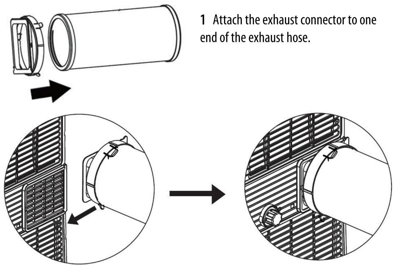
2 Attach the exhaust hose to the air outlet at the back of the appliance.
Wall installation
- Cut a 125mm hole into the wall for the wall exhaust adapter.
-
Secure the wall exhaust adapter to the wall using the four supplied anchors and screws.
-
Connect the exhaust hose assembly to the wall exhaust adapter.
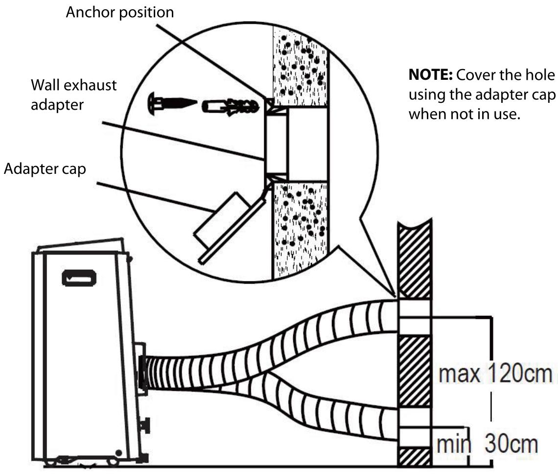

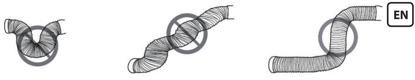
NOTE: To ensure proper functioning, DO NOT over-extend or bend the hose. To ensure the exhaust system works properly, make sure that there is no obstacle around the air
outlet of the exhaust hose (in the range of 500mm ).
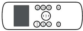
OPERATION
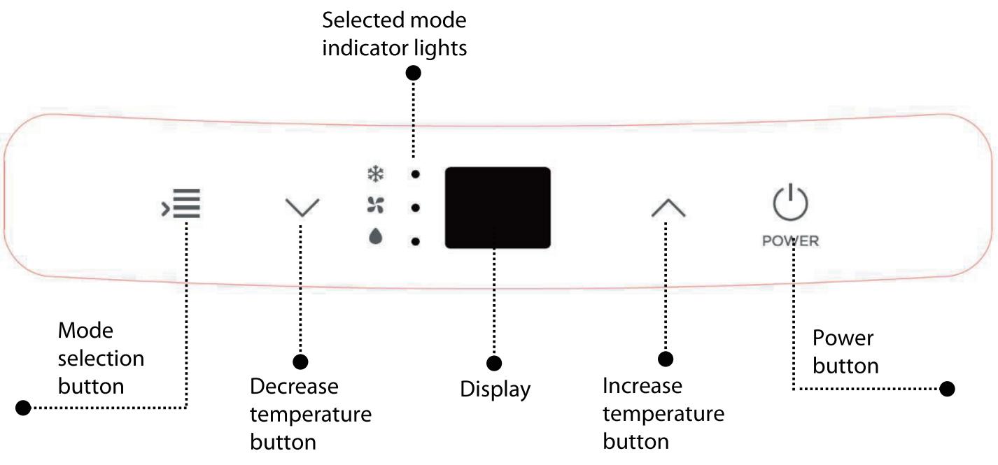
CONTROL PANEL
Turning the appliance on or off
Plug in the appliance.
Press to turn the appliance on.
To turn off the appliance, press again.
MODE
Repeatedly press to select the appropriate operating mode. The selected mode indicator light will illuminate on the control panel.

The exhaust hose needs to be used during COOL MODE operation.
- Repeatedly press > until the COOL indicator light illuminates.
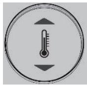
- Repeatedly press or to select the desired room temperature.
The and buttons are used to increase or decrease the temperature settings in 1^ increments.
The temperature range can be set from 17^ to 30^
NOTE: The temperature can be displayed in either degrees Fahrenheit or degrees Celsius. To convert from one to the other, press and hold and at the same time for 3 seconds.
- Repeatedly press on the remote control to choose adjust the fan speed.
FAN MODE

The exhaust hose is not required during FAN MODE operation.
- Repeatedly press > until the FAN indicator light illuminates.
- Repeatedly press
The temperature cannot be adjusted in this mode.
DRY/DEHUMIDIFY MODE

The exhaust hose is not required during DRY MODE operation.
Repeatedly press > until the DRY indicator light illuminates.
The fan speed or temperature cannot be set. The fan will automatically operate at LOW speed.
NOTE: Keep windows and doors closed for the best dehumidifying effect.
LED DISPLAY
The LED display shows the set temperature in COOL mode. While in DRY or FAN mode, it shows the ambient room temperature.
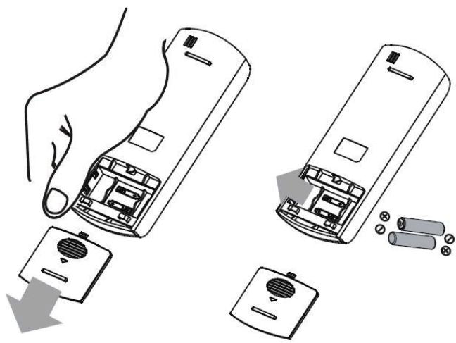
Battery installation
- Slide the battery cover off the remote control.
- Insert the supplied batteries, paying attention to match up the (+) and (-) ends of the batteries with the symbols inside the battery compartment.
- Slide the battery cover back into place.

TIPS FOR USING REMOTE CONTROL
- Point the remote control at the receiver on the appliance. The remote control must be no more than 8 meters away from the appliance (without obstacle between the remote and receiver).
- The appliance will beep when remote signal is received.
- Curtains, other materials and direct sunlight can interfere with the infrared signal receiver.
- Remove batteries if the remote will not be used for more than 2 months.
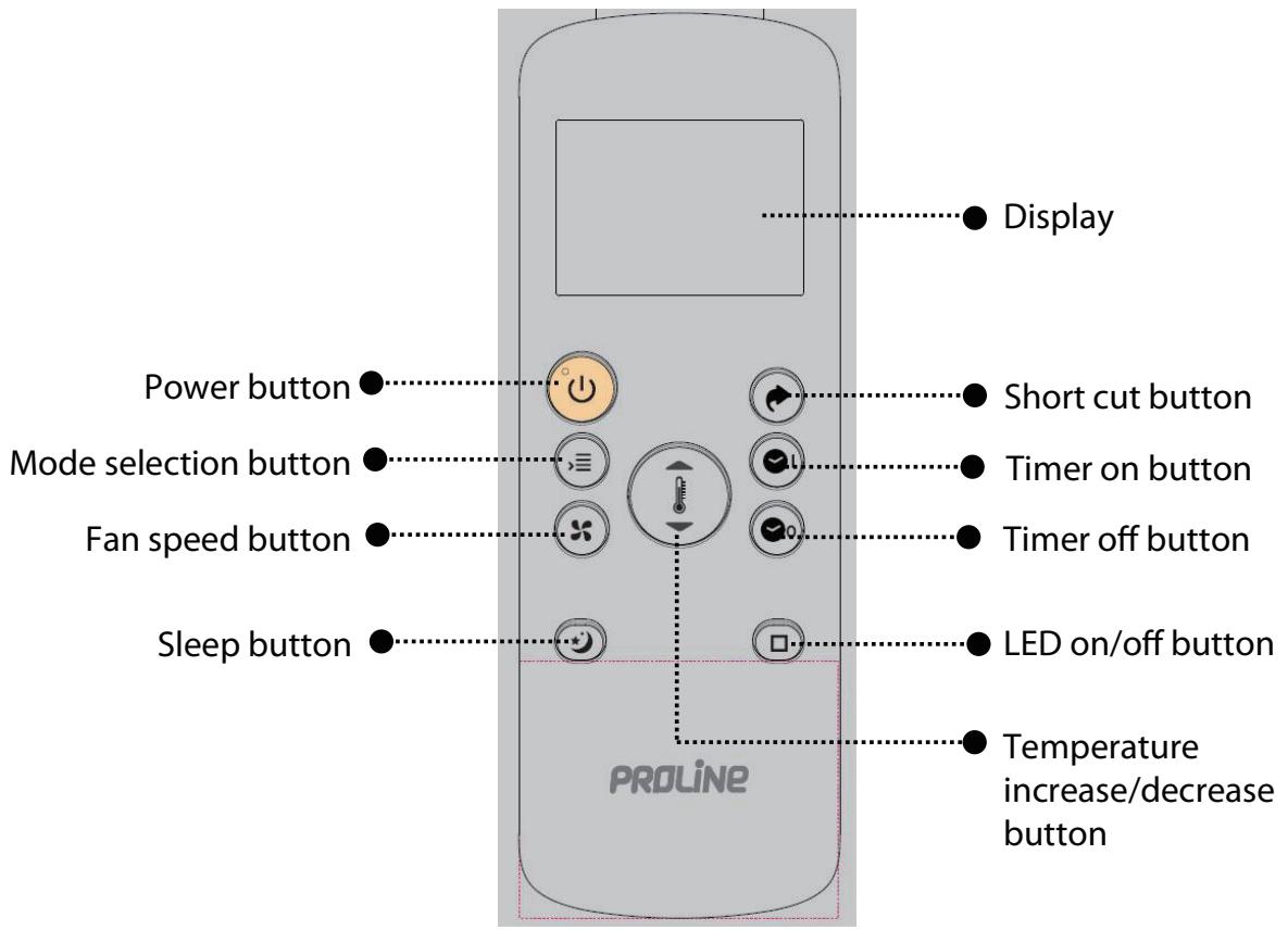
Remote control
EN
LED display indicators
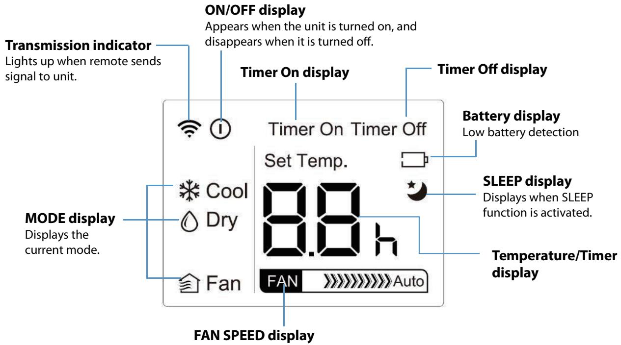
Power button

Press this button to turn the appliance ON or OFF.
The remote display will show when buttons are pressed to show that the remote control is sending a signal to the air conditioner.
To turn the control panel display on or off, press
Mode button

Repeatedly press this button to select the Cool, Dry or Fan mode.
The corresponding symbol will illuminate on the remote display to indicate which mode is selected.

Cool mode

Repeatedly press or until the desired temperature is displayed on the remote display.
Repeatedly pre

to select the desired fan speed.

Low speed

High speed

Auto speed

Dry / Dehumidify mode

Repeatedly press or until the desired temperature is displayed on the remote display.
In this mode, fan speed can not be changed.

Fan mode


Repeatedly press to select the desired fan speed.
In this mode, the temperautre cannot be changed and the remote display will not show temperature.
Setting the timer function
Your air conditioner has two timer-related functions:
TIMER ON – sets the amount of timer after which the unit will automatically turn on.
TIMER OFF -sets the amount of time after which the unit will automatically turn off.

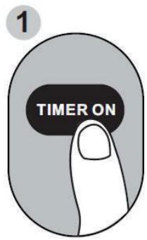
TIMERONfunction

The TIMER ON function allows you to set a period of time after which the unit will automatically turn on, such as when you come home from work.


-
When the unit is OFF, press
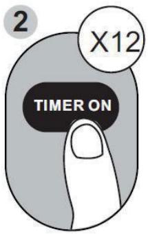
-
By default, the last time period that you set and an "h" (indicating hours) will appear on the display.
- Note: This number indicates the amount of time after the current time that you want the unit to turn on. For example, if you set TIMER ON for 2 hours, the remote display will show “2.0h”, and the unit will turn on after 2 hours.

- Repeatedly press to set the time when you want the unit to turn on.
- Wait for 2 seconds, then the TIMER ON function will be activated.

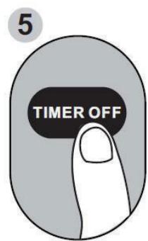
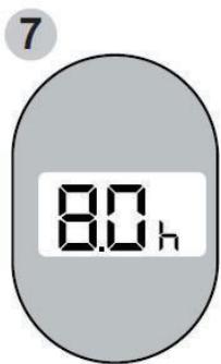
TIMER OFF function
The TIMER OFF function allows you to set a period of time after which the unit will automatically turn off, such as when you wake up.

-
When the unit is ON, press
-
By default, the last time period that you set and an "h" (indicating hours) will appear on the display.
-
Note: This number indicates the amount of time after the current time that you want the unit to turn off. For example, if you set TIMER OFF for 2 hours, the remote display will show “2.0h”, and the unit will turn off after 2 hours.
-
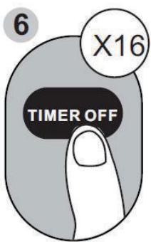
Repeatedly press to set the time when you want the unit to turn off.
- Wait for 2 seconds, then the TIMER OFF function will be activated.
NOTE: When setting the TIMER ON or TIMER OFF function, up to 10 hours, the time will increase in 30 minute increments with each press. After 10 hours and up to 24 hours, it will increase in 1 hour increments.
To cancel the TIMER ON or TIMER OFF function, set the timer to "0.0h".
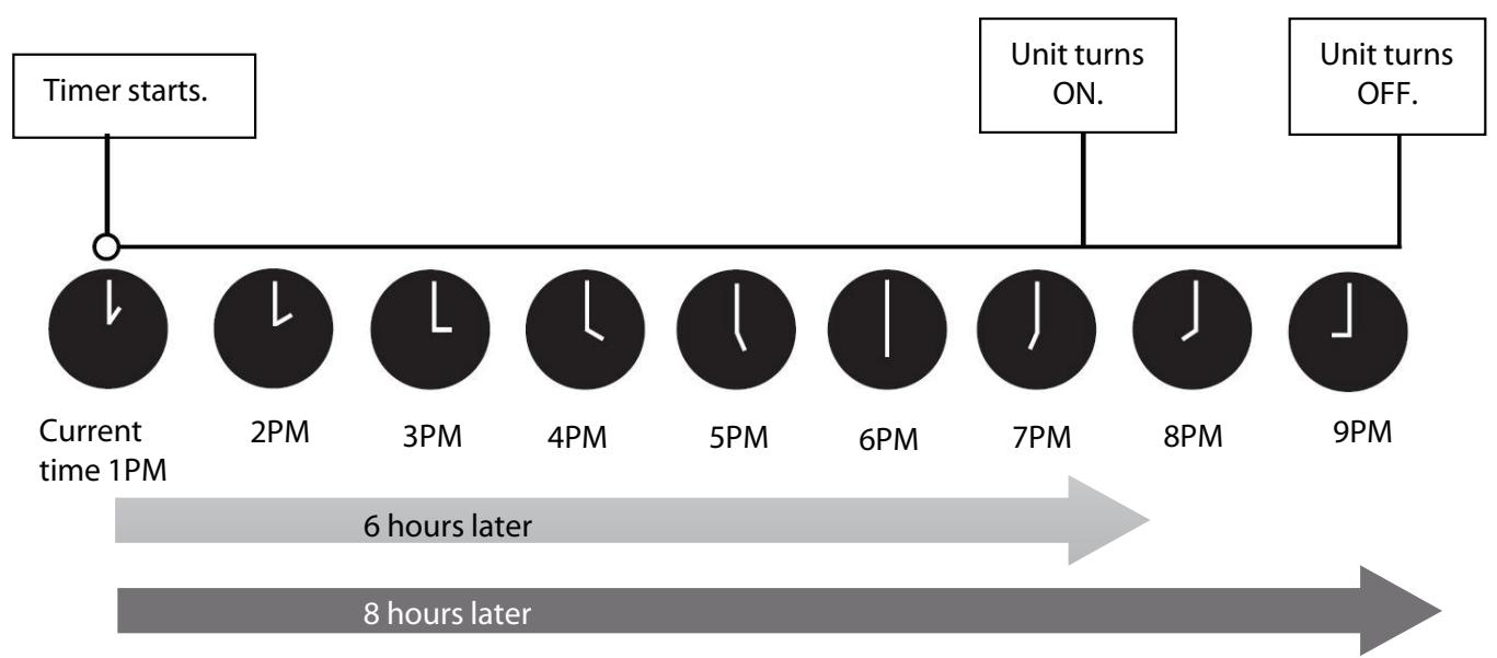
Setting both TIMER ON and TIMER OFF at the same time
Keep in mind that the time periods you set for both functions refer to hours after the current time. For example, say that the current time is 1:00 PM, and you want the unit to turn on automatically at 7:00 PM. You want it to operate for 2 hours, then automatically turn off at 9:00 PM.
Do the following:
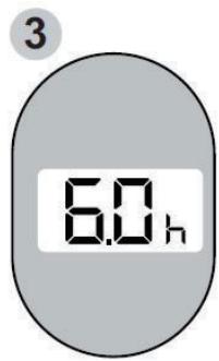
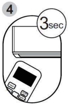
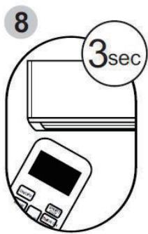
Example: Setting the unit to turn on after 6 hours, operate for 2 hours, then turn off.
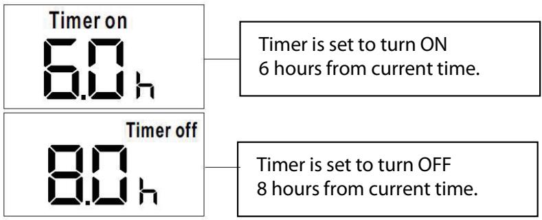
Your remote display

Sleep

The SLEEP function gradually adjusts the temperature of the room to provide a comfortable

environment. Press to activate the function.
- In COOL mode, the temperature will increase by 1^ in 30 minutes and then increase by 2^ after an additional 30 minutes.
-
This new temperature will be maintained for 7 hours before it returns to the original selected temperature. This ends the Sleep function and the unit will continue to operate as originally programmed.
-
To cancel this function press again.
NOTE: The SLEEP function cannot be used under FAN or DRY mode.
SHORTCUT function

- Used to restore the current settings or resume previous settings.
- Press this button when remote control is on, the system will automatically revert back to the previous settings including operating mode, set temperature, fan speed and sleep function (if activated).
- If keeping this button pressed for more than 2 seconds, the system will automatically restore the current operation settings including operating mode, set temperature, fan speed and sleep function (if activated).
AUTO-RESTART
If the appliance turns off unexpectedly due to a power cut, it will automatically restart in the previous settings when the power resumes.
WAIT 3 MINUTES BEFORE RESUMING OPERATION
After the appliance has been turned off, it can not be restarted in the first 3 minutes. This is to protect the appliance. Operation will automatically start after 3 minutes.
AIR FLOW DIRECTION ADJUSTMENT
The louvres need to be adjusted manually.
- Angle the louvres in the direction required.
- Do not place any heavy objects on or block the louvres, doing so will cause damage to the appliance.
- Ensure the louvre is always fully opened during operation.
POWER MANAGEMENT
Under cooling operation, when the ambient temperature is lower than the set temperature for a period of time, the appliance will automatically operate the power management feature. The compressor and fan motor will stop. When the ambient temperature is higher than the set temperature, the appliance will automatically quit power management mode and the compressor and/or fan motor will run.
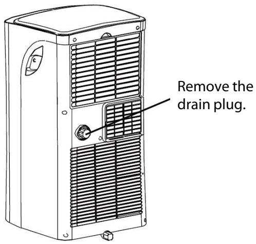
WATER DRAINAGE
Unplug the appliance from the power source.
During DRY/dehumidify mode, remove the drain cap and plug located in the back center of the appliance. While doing this operation, some residual water may spill so have a drip pan (not supplied) to collect the water.
Connect the supplied drain hose as shown. The water can be continuously drained through the hose into a floor drain.

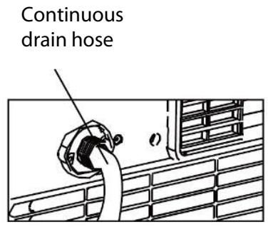

NOTE: Make sure the hose is secure so there are no leaks. Direct the hose toward the drain, making sure that there are no kinks that will stop the warter flowing. Place the end of the hose into the drain and make sure the end of the hose is down to let the water flow smoothly. When the continuous drain hose is not used, ensure that the drain plug and knob are installed firmly to prevent leakage.
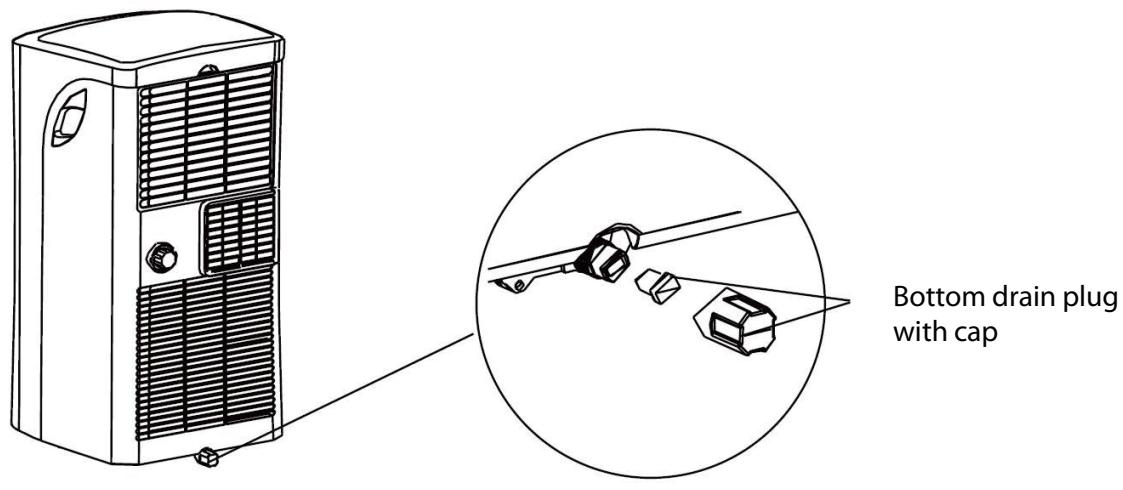
When the water level of the bottom tray reaches a predetermined level, the appliance will beeps and the display will show "P1". At this time the cooling/dehumidification process will immediately stop. However, the fan motor will continue to operate (this is normal). Carefully move the appliance to a drain location, remove the bottom drain plug and let the water drain away. Reinstall the bottom drain plug and restart the machine until the "P1" disappears. If the error repeats, call for service.
NOTE: Be sure to reinstall the bottom drain plug firmly to prevent leakage before using the appliance.
WARNING: Before cleaning or maintenance, turn the appliance off by pressing

on the control panel or on the remote control. Unplug from the mains socket.
EN
Cleaning the outside cabinet
Clean the surface of the appliance with a slightly damp cloth and then dry with a dry cloth.
- Never use flammable liquids or chemicals to clean the appliance.
- Never wash the appliance under running water. Doing so causes electrical danger.
IMPORTANT
The control panel and other parts must not come into contact with water or any other liquid.
Cleaning the filter
CAUTION: DO NOT operate the appliance without filter because dirt and lint it and reduce performance.
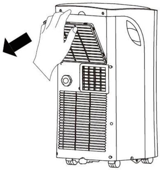
- Be sure to clean the air filter every 2 weeks for optimal performance.
- Use a vacuum cleaner to remove dust accumulations from the filter. Ifit is very dirty, clean the filter under running water. Leave the filter to dry and then re-insert the filter.
In households with animals, you will have to periodically wipe the grille to prevent blocked airflow due to animal hair.
Storage
If you are not using the appliance for an extended period of time. After cleaning please:
- Turn off and unplug the appliance.
- Make sure the water is completely drained.
- Run the appliance on FAN mode for 12 hours in a warm room to dry it and prevent mould.
- Clean the filter as described in the previous section.
- Remove batteries from the remote control.
- Cover the appliance and store it upright in a location where it will not receive direct sunlight.
TROUBLESHOOTING
| Problem | Possible Cause | Solution |
| Unit does not turn on when pressing ON/OFF button. | P1 Protection Code | Turn off the unit, drain the water and restart the unit. |
| In COOL mode: room temperature is lower than the set temperature. | Reset the temperature. | |
| E0 EEPROM error | Contact the service agents or a similar qualified person for service. | |
| Unit does not cool well. | The air filter is blocked with dust or animal hair. | Turn off the unit and clean the filter. |
| Exhaust hose is not connected or is blocked. | Turn off the unit, disconnect the hose, check for blockage and reconnect the hose. | |
| The unit is low on refrigerant. | Call a service technician to inspect the unit and top off refrigerant. | |
| Temperature setting is too high. | Decrease the set temperature. | |
| The windows and doors in the room are open. | Make sure all windows and doors are closed. | |
| The room area is too large | Check the cooling area. | |
| There are heat sources inside the room. | Remove the heat sources if possible. | |
| The unit is noisy and vibrates too much. | The ground is not level. | Place the unit on a flat, level surface. |
| The air filter is blocked with dust or animal hair. | Turn off the unit and clean the filter. | |
| The unit makes a gurgling sound. | This sound is caused by the flow of refrigerant inside the unit. | This is normal. |

ERROR CODES
E0 - EEPROM (Electrical Erasable Read-Only Memory) error
E1 - Room temperature sensor error.
E2 - Evaporator temperature sensor error.
E3 - Condenser temperature sensor error.
E4 - Display panel communication error.
EC - Refrigerant leakage detection malfunction.
Protection code:
P1 - Bottom tray is full. Connect the drain hose and drain the collected water. If protection repeats, call for technical assistance.
NOTE: When one of the above malfunctions occurs, turn the unit OFF, and check for any obstructions. Restart the unit, if the malfunction is still present, turn OFF the unit and unplug the power cord. Contact the service agents or a similar qualified person for service.
SPECIFICATIONS
| Product fiche | |||
| Trade mark | Proline | ||
| Model | PAC1800 | ||
| Energy efficiency class | A | ||
| Description | Symbol | Value | Unit |
| Rated capacity for cooling | \(P_{rated}\) for cooling | 2,0 | kW |
| Rated power input for cooling | \(P_{EER}\) | 0,8 | kW |
| Rated Energy efficiency ratio | \(\mathsf{EER_d}\) | 2,6 | — |
| Power consumption in thermostat-off mode | \(P_{TO}\) | — | W |
| Power consumption in standby mode | \(P_{SB}\) | 0,5 | W |
| Electricity consumption of single duct appliances | \(Q_{SD}\) | 0,8 | kWh/h |
| Energy consumption 0,8 kWh per 60 minutes, based on standard test results. Actual energy consumption will depend on how the appliance is used and where it is located. | |||

| Sound power level | LWA | 62 | dB(A) |
| Global warming potential | GWP | 3 | kgCO2eq. |
| Refrigerant leakage contributes to climate change. Refrigerant with lower global warming potential (GWP) would contribute less to global warming than a refrigerant with higher GWP, ifleaked to the atmosphere. This appliance contains a refrigerant fluid with a GWP equal to 3. This means that if 1 kg of this refrigerant fluid would be leaked to the atmosphere, the impact on global warming would be 3 times higher than 1 kg of CO2, over a period of 100 years. Never try to interfere with the refrigerant circuit yourself or disassemble the product yourself and always ask a professional. (Refrigerant: R290 / 0,14 kg) | |||
| Contact detail for obtaining more information | Etablissements Darty & fils © 129 Avenue Gallieni, 93140 Bondy, France Website: www.darty.com | ||
EN
NOTE: The Energy consumption 0,8 kWh per 60 minutes was rounded to Energy consumption 1 kWh per 60 minutes in energy label as per regulation EU 626/2011 and its amending.
DISPOSAL
As a responsible retailer we care about the environment. As such we urge you to follow the correct disposal procedure for the appliance and packaging materials. This will help conserve natural resources and ensure that it is recycled in a manner that protects health and the environment.
You must dispose of this appliance and its packaging according to local laws and regulations. Because this appliance contains electronic components, the appliance and its accessories must be disposed of separately from household waste when the appliance reaches its end of life.
Contact your local authority to learn about disposal and recycling.
The appliance should be taken to your local collection point for recycling. Some collection points accept
appliance free of charge.
We apologise for any inconvenience caused by minor inconsistencies in these instructions, which may occur as a result of product improvement and development.
Type:334, Tension: 250V, Courant: 3,15A
FR
FR
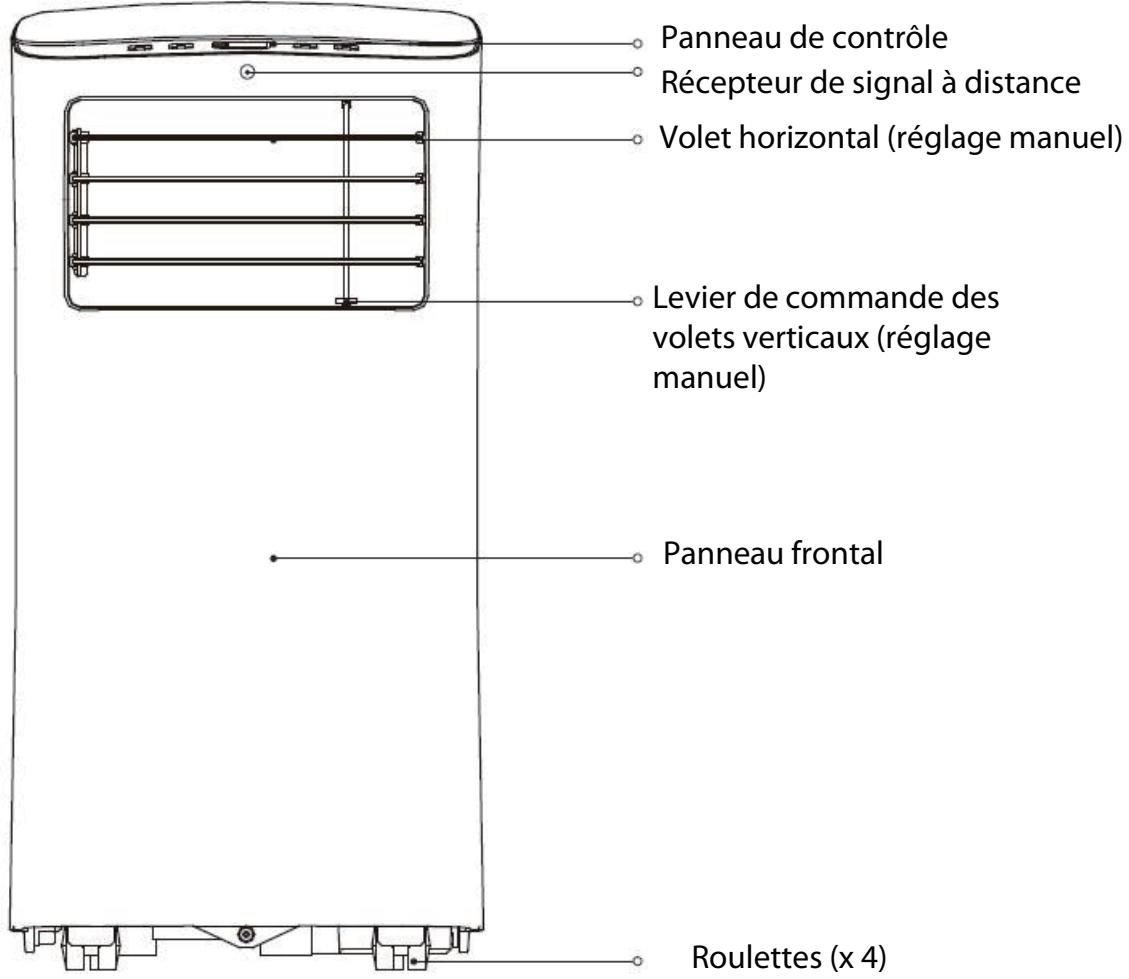
Vue avant
FR
Vue arrirée

Accessoires
Hotline Darcy France

Transmissie-indicator:
Cool

Dry

Fan

FAN

Auto
Weergave van slaapstand
A区内应有100名工人。
A区域内应有100名工人。
A few workers in the area should be hired.
A few workers in the area should be hired.
5. Presença do extintor de incéndios
EU Declaration of Conformity
Product Description:
The object of the declaration described above is in conformity with the relevant Union
harmonisation legislation:
Low Voltage Directive (LVD)
Eco design requirements for energy-related products (ErP)
RoHS
EMC:
EN 55014-1:2017+A11:2020
EN 55014-2:2015
EN IEC 61000-3-2:2019
EN 61000-3-3:2013+A1:2019
LVD :
EN 60335-1:2012+A11:2014+A13:2017+A1:2019+A14:2019+A2:2019
EN 60335-2-40:2003+A11:2004+A12:2005+A1:2006+A2:2009+A13:2012
EN 62233:2008
ErP :
(EU) No 206/2012
(EU) No 626/2011
(EU) 2016/2282
(EU) 2017/254
EN 14511-2:2018
EN 14511-3:2018
EN 50564:2011
EN 12102-1:2017
This declaration of conformity is drawn up under the sole responsibility of the manufacturer.
The person responsible for this declaration is:
Fonction - Position: General Manager Direct Sourcing
Place, Date / Lieu :
Bondy, novembre 29, 2021