
CYLINDRA - Range hood FABER - Free user manual and instructions
Find the device manual for free CYLINDRA FABER in PDF.
| Product Type | Range Hood |
| Brand | Faber |
| Model | CYLINDRA |
| Usage | Indoor, domestic |
| Power Supply | 120 V, 60 Hz, 15 A, dedicated circuit |
| Motor Power | Variable by speed (max CFM not specified) |
| Installation Type | External venting or recirculation (with charcoal filter) |
| Duct Diameter | 6 inches (round, rigid metal) |
| Minimum Installation Height | 24 inches (61 cm) above cooking surface |
| Lighting | Halogen (replaceable) |
| Controls | Touch panel and wireless remote control (optional) |
| Speeds | Multi-speed + intensive (boost) function for 10 minutes |
| 24-Hour Function | Runs 10 min/h at low speed (60 CFM, 0.5 sones) |
| Delayed Shut-off Function | 30 minutes |
| Grease Filters | Metal, dishwasher safe |
| Charcoal Filter (optional) | For recirculation, replace every 4-6 months |
| Filter Saturation Alarm | LED display: FF (grease) after 100 h, EF (charcoal) after 200 h |
| Materials | Stainless steel |
| Warranty | 1 year (parts and labor) |
| Safety Standards | UL / C-UL listed |
Frequently Asked Questions - CYLINDRA FABER
User questions about CYLINDRA FABER
0 question about this device. Answer the ones you know or ask your own.
Ask a new question about this device
Download the instructions for your Range hood in PDF format for free! Find your manual CYLINDRA - FABER and take your electronic device back in hand. On this page are published all the documents necessary for the use of your device. CYLINDRA by FABER.
USER MANUAL CYLINDRA FABER
- Installation Instructions
- Use and Care Information
READ AND SAVE THESE INSTRUCTIONS
The Installer must leave these instructions with the homeowner. The homeowner must keep these instructions for future reference and for local electrical inspectors' use.
READ THESE INSTRUCTIONS BEFORE YOU START INSTALLING THIS RANGEHOOD
WARNING: - TO REDUCE THE RISK OF A RANGE TOP GREASE FIRE: a) Never leave surface units unattended at high settings. Boilovers cause smoking and greasy spillovers that may ignite. Heat oils slowly on low or medium setting. b) Always turn hood ON when cooking at high heat or when flambeing food (i.e. Crepes Suzette, Cherries Jubilee, Peppercorn Beef Flambé). c) Clean ventilating fans frequently. Grease should not be allowed to accumulate on fan or filter. d) Use proper pan size. Always use cookware appropriate for the size of the surface element.
WARNING: - TO REDUCE THE RISK OF INJURY TO PERSONS IN THE EVENT OF A RANGE TOP GREASE FIRE, OBSERVE THE FOLLOWING: SMOTHER FLAMES with a close-fitting lid, cookie sheet, or metal tray, then turn off the burner. BE CAREFUL TO PREVENT BURNS. If the flames do not go out immediately EVACUATE AND CALL THE FIRE DEPARTMENT. NEVER PICK UP A FLAMING PAN - You may be burned. DO NOT USE WATER, including wet dishcloths or towels - a violent steam explosion will result. Use an extinguisher ONLY if: 1. You know you have a Class ABC extinguisher, and you already know how to operate it. 2. The fire is small and contained in the area where it started. 3. The fire department is being called. 4. You can fight the fire with your back to an exit.
ALL WALL AND FLOOR OPENINGS WHERE THE RANGEHOOD IS INSTALLED MUST BE SEALED.
This rangehood requires at least 24^ of clearance between the bottom of the rangehood and the cooking surface or countertop. This minimum clearance may be higher depending on local building code. For example, for gas ranges, a minimum of 30^ may be required. Overhead cabinets on both sides of this unit must be a minimum of 18^ above the cooking surface or countertop. Consult the cooktop or range installation instructions given by the manufacturer before making any cutouts. MOBILE HOME INSTALLATION The installation of this rangehood must conform to the Manufactured Home Construction and Safety Standards, Title 24 CFR, Part 3280 (formerly Federal Standard for Mobile Home Construction and Safety, Title 24, HUD, Part 280). Four wire power supply must be used and the appliance wiring must be revised. See Electrical Requirements.
LISEZ BIEN CETTE FICHE AVANT D'INSTALLER LA HOTTE
Determine which venting method is best for your application. Ductwork can extend either through the wall or the roof.
The length of the ductwork and the number of elbows should be kept to a minimum to provide efficient performance. The size of the ductwork should be uniform. Do not install two elbows together. Use duct tape to seal all joints in the ductwork system. Use caulking to seal exterior wall or floor opening around the cap.
Flexible ductwork is not recommended. Flexible ductwork creates back pressure and air turbulence that greatly reduces performance.
Make sure there is proper clearance within the wall or floor for exhaust duct before making cutouts. Do not cut a joist or stud unless absolutely necessary. If a joist or stud must be cut, then a supporting frame must be constructed
FOR MORE SPECIFIC DUCTWORK INFORMATION, GO TO PAGE 4.
WARNING - To Reduce The Risk Of Fire, Use Only Metal Ductwork.
Cold Weather installations
An additional back draft damper should be installed outside to minimize backward cold air flow and a nonmetallic thermal break should be installed to minimize conduction of outside temperatures as part of the vent system. The damper should be on the cold air side of the thermal break. The break should be as close as possible to where the vent system enters the heated portion of the house.
WARNING
- Venting system MUST terminate outside the home.
- DO NOT terminate the ductwork in an attic or other enclosed space.
- DO NOT use 4" laundry-type wall caps.
- Flexible-type ductwork is not recommended.
DO NOT obstruct the flow of combustion and ventilation air. - Failure to follow venting requirements may result in a fire.
ELECTRICAL REQUIREMENTS
A 120 volt, 60Hz AC-only electrical supply is required on a separate 15 amp fused circuit. A time-delay fuse or circuit breaker is recommended. The fuse must be sized per local codes in accordance with the electrical rating of this unit as specified on the serial/rating plate located inside the unit near the field wiring compartment. THIS UNIT MUST BE CONNECTED WITH COPPER WIRE ONLY. Wire sizes must conform to the requirements of the National Electrical Code, ANSI/NFPA 70 - latest edition, and all local codes and ordinances. Wire size and connections must conform with the rating of the appliance. Copies of the standard listed above may be obtained from:
National Fire Protection Association
Batterymarch Park
Quincy, Massachusetts 02269
For residential use only.
This appliance should be connected directly to the fused disconnect (or circuit breaker) through flexible, armored or nonmetallic sheathed copper cable. Allow some slack in the cable so the appliance can be moved if servicing is ever necessary. A UL Listed, 1/2" conduit connector must be provided at each end of the power supply cable (at the appliance and at the junction box).
When making the electrical connection, cut a 1 1/4 hole in the wall. A hole cut through wood must be sanded until smooth. A hole through metal must have a grommet.
WARNING- TO REDUCE THE RISK OF FIRE ELECTRIC SHOCK, do not use this fan with any solid-state speed control device.
WARNING - TO REDUCE THE RISK OF FIRE, ELECTRICAL SHOCK, OR INJURY TO PERSONS, OBSERVE THE FOLLOWING: Use this unit only in the manner intended by the manufacturer. If you have any questions, contact the manufacturer.
Before servicing or cleaning unit, switch power off at service panel and lock the service disconnecting means to prevent power from being switched on accidentally. When the service disconnecting means cannot be locked, securely fasten a prominent warning device, such as a tag, to the service panel.
CAUTION: For General Ventilating Use Only. Do Not Use To Exhaust Hazardous or Explosive Materials and Vapors.
WARNING - TO REDUCE THE RISK OF FIRE, ELECTRICAL SHOCK, OR INJURY TO PERSONS, OBSERVE THE FOLLOWING: Installation Work And Electrical Wiring Must Be Done By Qualified Person(s) In Accordance With All Applicable Codes And Standards, Including Fire-Rated Construction.
Sufficient air is needed for proper combustion and exhausting of gases through the flue (chimney) of fuel burning equipment to prevent backdrafting. Follow the heating equipment manufacturer's guideline and safety standards such as those published by the National Fire Protection Association (NFPA), and the American Society for Heating, Refrigeration and Air Conditioning Engineers (ASHRAE), and the local code authorities.
When cutting or drilling into wall or ceiling, do not damage electrical wiring and other hidden utilities.
Ducted fans must always be vented to the outdoors.
WARNING
- Electrical ground is required on this rangehood.
- If cold water pipe is interrupted by plastic, nonmetallic gaskets or other materials, DO NOT use for grounding.
DO NOT ground to a gas pipe. - DO NOT have a fuse in the neutral or grounding circuit. A fuse in the neutral or grounding circuit could result in electrical shock.
- Check with a qualified electrician if you are in doubt as to whether the rangehood is properly grounded.
- Failure to follow electrical requirements may result in a fire.
RÉGLEMENTS D'ÉVACUATION
- Saber Saw or Jig Saw
- Drill
- 1 1/4" Wood Drill Bit
- Scissors
- Pliers
- Phillips Screwdriver
- Flat Blade Screwdriver
- Wire Stripper or Utility Knife
Metal Snips - Measuring Tape or Ruler
- Level
- Pencil
Caulking Gun - Duct Tape
PARTS SUPPLIED FOR INSTALLATION
- 1 Hardware Package
1 Literature Package
PARTS NEEDED FOR INSTALLATION
- 2 Conduit Connectors
- Power Supply Cable
1 Wall or Roof Cap - All Metal Ductwork
OPTIONAL ACCESSORIES AVAILABLE
Glass Kit
20" deep by 36" wide glass "canopy" that mounts to the bottom of the Cylinder Part # GLSCYLN
- Charcoal Filter Kit
For non-vented installations only
- it is highly recommended that professional style cooking always be vented to the outside part #620000041
CFM reduction kit
For make up air environments, converts the Cfm of this hood to under 300 cfm part #CFMRED
- Remote Control
Use a wireless remote to operate the rangehood part #REMCTRL
WARNING
PERSONAL INJURY HAZARD
Because of the weight and size of the rangehood canopy, two or more people are needed to move and safely install the rangehood canopy.
Failure to properly lift rangehood could result in damage to the product or personal injury.
This rangehood can be installed as either ducted or ductless. When ducting outside, the blower can be vented through the wall or ceiling. To vent through a wall, a 90^ elbow is used. When installed ductless, the rangehood vents out of the top of the chimney. Ductless installations require Charcoal Filters, available from your dealer.
WARNING! BEFORE MAKING ANY CUTS OR HOLES FOR INSTALLATION, DETERMINE WHICH VENTING METHOD WILL BE USED AND CAREFULLY CALCULATE ALL MEASUREMENTS.
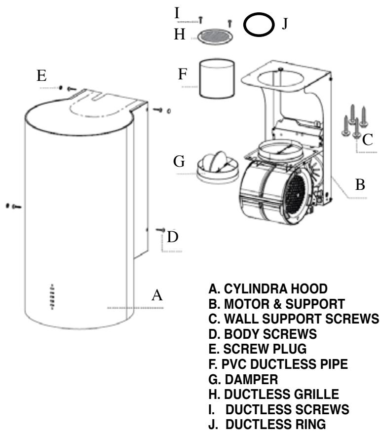
RANGEHOOD COMPONENTS
FIGURE 1
CALCULATE THE DUCTRUN LENGTH
The ductrun should not exceed 35 equivalent feet if ducted with the required minimum of 6'' round duct. Calculate the length of the ductwork by adding the equivalent feet in FIGURE 2 for each piece of duct in the system. An example is given in FIGURE 3.
45^ Elbow 3.0 feet
90^ Elbow 5.0 feet
90^ Flat Elbow 12.0 feet
Wall Cap 0.0 feet
FIGURE 2
9 Feet Straight Duct 9.0 feet
2-90° Elbows 10.0 feet
Wall Cap 0.0 feet
Total System 19.0 feet
FIGURE 3
For best results, use no more than three 90^ elbows. Make sure that there is a minimum of 24^ of straight duct between elbows if more than one is used. Do not install two elbows together. If you must elbow right away, do it as far away from the hood's exhaust opening as possible.
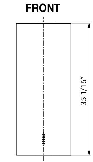
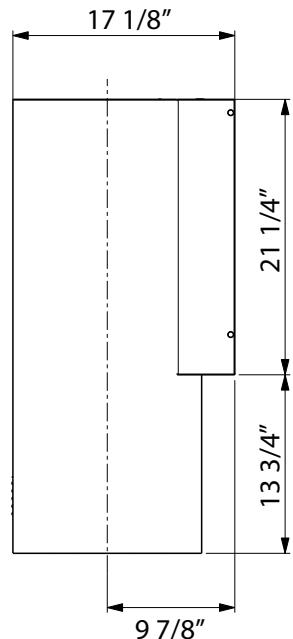
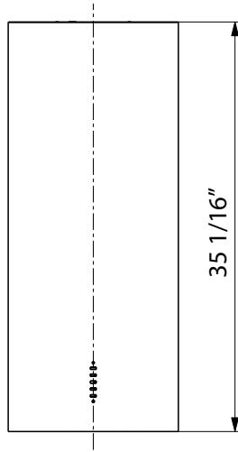
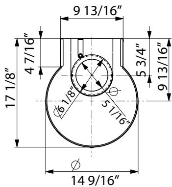
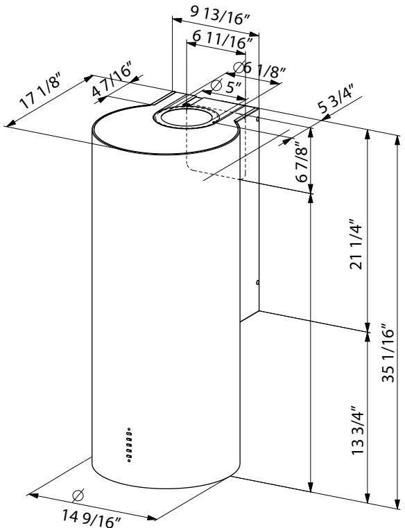
PRODUCT DIMENSIONS
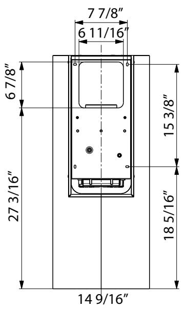
BACK
SIDE
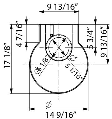
TOP
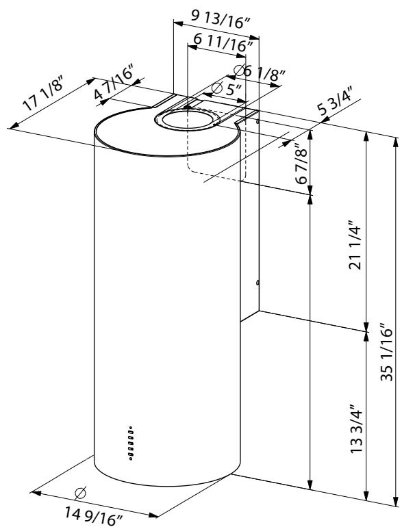
OVERALL
NOTE: The installation diagram in FIGURE 4 on the next page is used for the recommended installation height of 24'' off the cooktop. For maximum installation heights of up to 30'' off the cooktop, add onto the horizontal line of 425/16'' in FIGURE 4. For example add 6'' , or 485/16'' total, to install 30'' off the cooktop.
NOTE: For 8'' ceilings, the Cylinder should be installed at 24'' off the cooktop and the hood is mounted at the ceiling. For higher ceilings, the Cylinder is mounted at 24 - 30'' off the cooktop and is installed "floating" in the middle of the wall, not at the ceiling.
DUCTED INSTALLATIONS
NOTE: When installing the hood in the ductless version, leave at least 4'' between the top of the hood and the ceiling for proper air circulation.
PREPARE THE WALL FOR ALL INSTALLATIONS
- Disconnect and move freestanding range from cabinet opening to provide easier access to rear wall. Put a thick, protective covering over cooktop, set-in range or countertop to protect from damage or dirt.
- Determine and clearly mark with a pencil the center line on the wall where the rangehood will be installed.
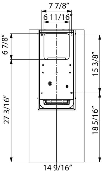
- Draw a Horizontal line at a minimum of 425 / 16'' above the Cooktop, see (FIGURE 4 for reference)
- Drill 2 holes at 315 / 16'' to the right and left of this line. Check that the two marks are level, before drilling.
- Mark a reference point at 15 38 above the 42 516 line in step #3 and drill 2 holes 3 1516 to the right and left of this line. Check that the two marks are level, before drilling.
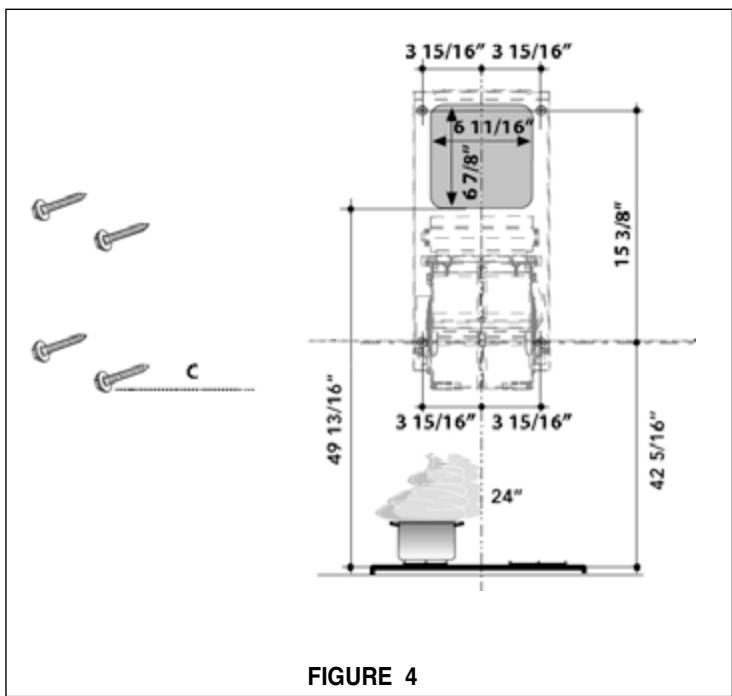
- Attach the motor and wall support (B in FIGURE 5), using the 4 - (C) wall support screws.
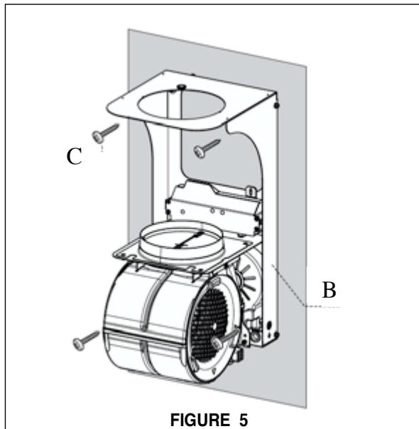
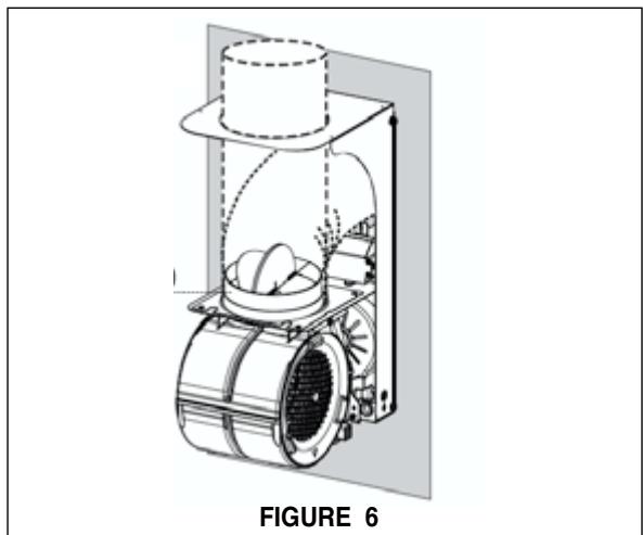
- The Cylinder hood offers flexibility in ducting. See (FIGURE 6), using 6'' rigid metal ducting, the hood can be ducted straight up or with an elbow to the back of the hood at the 6 7/8" tall x 6 11/16" wide opening next to the wall.
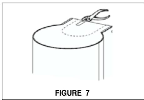
- If ducting out of the top of the hood, carefully remove the pre cut metal piece at the top of the hood body (FIGURE 7).
- Attach the Damper (G in FIGURE 1), connect rigid metal 6 inch round ducting to the damper and seal the duct with tape
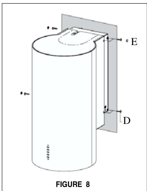
- For all ducting directions, using 4 screws (D in FIGURE 8), to attach the hood body to the support frame on the wall, cover screws with (E screw covers in FIGURE 8).
DUCTLESS INSTALLATIONS
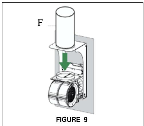
- Install provided PVC pipe directly on top of the motor, and seal with tape. F in FIGURE 9.
- Remove the pre cut piece at the top of the hood body (FIGURE 7). Using 4 screws (D in FIGURE 8), to attach the hood body to the support frame on the wall, cover screws with (E screw covers in FIGURE 8).
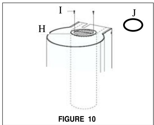
- Install the ductless grille and then the stainless ring above it with 2 screws (H, I, J in FIGURE 10).
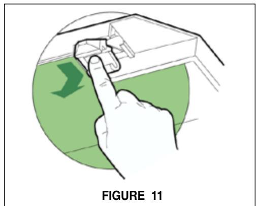
- Install the charcoal filters (sold seperately) above the perimetric comfort panel and the grease filter, see (FIGURE 11) for installation. Remove the grease filter and position the charcoal filter with the pull tabs facing out and forward then snap into place. Place grease filter back into place.
FOR ALL INSTALLATIONS
-
Install the SS comfort panel as in FIGURE 14, to the bottom of the hood. Slide the fixing pin to install the hinge into place and lock the panel into place by pushing the panel up into the slot.
-
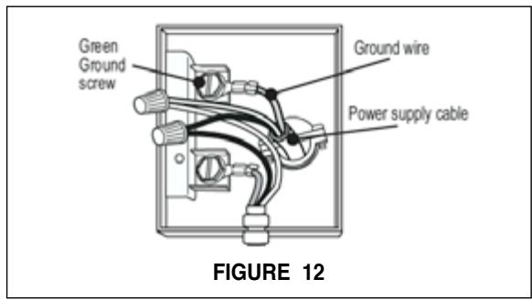
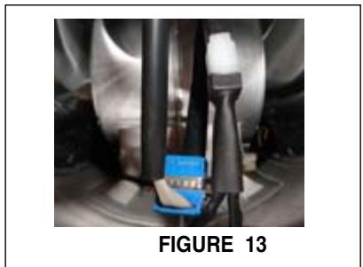
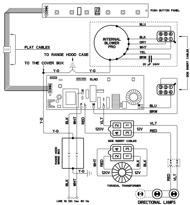
Remove the cover from the Field Wiring Compartment with a phillips screwdriver. Feed the Power Supply Cable through the electrical knockout. (See FIGURE 12) Connect the Power Supply Cable to the rangehood cable. Attach the White lead of the power supply to the White lead of the rangehood with a twist-on type wire connector. Attach the Black lead of the power supply to the Black lead of the rangehood with a twist-on type wire connector. Attach the Power Supply Cable grounding lead to the green screw provided. Using the 4 holes provided screw the Field Wiring Compartment to the wall as dictated by your Power Supply Cable location (screws not provided). Replace the cover. Next connect the control and lighting wires inside the hood above the grease filters as seen in (FIGURE 13).
- Turn the power supply on. Turn on blower and lights. If the rangehood does not operate, check that the circuit breaker is not tripped or the house fuse blown. If the unit still does not operate, disconnect the power supply and check that the wiring connections have been made properly.
USE AND CARE
The inside area of the perimetric comfort panel can be cleaned using a damp cloth and is opened by gently pulling the panel down on the front side. The panel can be removed from the hood by sliding the fixing pin to the side, see (FIGURE 14).
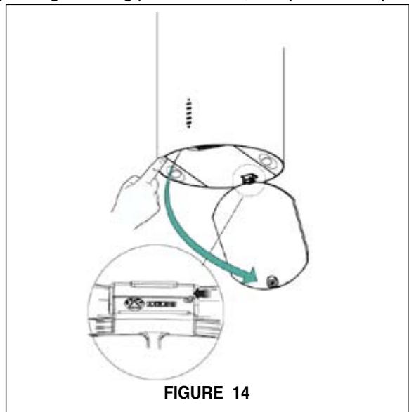
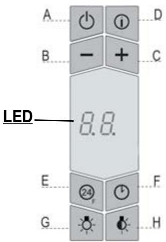
FIGURE 15
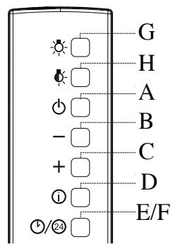
FIGURE 16
The hood can be operated from the control panel located on the front side of the hood or from the remote control, purchased separately.
FIGURE 15 is an illustration of the control panel and FIGURE 16 is the remote control illustration. On the remote control key E and F are controlled with one button. Press the button once for function key "F" - 30 minute shut down". Hold for 2 seconds for function key "E" - 24 hr function.
| Key A | Function Switches the blower motor on and off at the last selected speed | Related LED Display Symbol The current speed is shown when the hood is turned on. |
| B | Decreases the vent speed. | |
| C | Increases the vent speed. | |
| D | By pressing this key the intensive boost function is activated from any previously selected speed. The intensive boost can be activated even when the motor is OFF. After ten minutes of intensive power, the hood switches back to the last selected speed. This function is recommended for cooking conditions where vapors and odors need to be eliminated immediately and quickly. | HI appears. The red dot on the right side flashes |
| E | By pressing this key the 24 hr - function is set which turns the hood on at 60 CFM for 10 minutes every hour with a noise level of just .5 tones. This setting can operate all day and night to refresh and clean your home. After 10 minutes every hour, the motor switches off automatically. Press the button again to turn off the 24 hour function. When the grease or charcoal filter saturation alarm is triggered it is possible to reset the alarm by pressing this key for 3 seconds. The indication is visible only when the motor is off. | Indicates the 24 hr - function. The red dot on the right side flashes and the motor is on. FF Indicates that the metal grease filter saturation alarm has been triggered, and the filters need to be washed. The alarm is triggered after 100 hours of operation See the next page for instructions on resetting the alarm EF Indicates that the charcoal filter saturation alarm has been triggered, and the filter has to be replaced; The charcoal filter is triggered after 200 hours of operation. See the next page for instructions on resetting the alarm |
| F | By pressing this key the 30 minute delay shutdown mode is activated which is used to eliminate any residual odor in the kitchen for 30 minutes. After 30 minutes the hood turns off. It can be turned on at any speed, and it is turned off by pressing the key again or by switching off the motor. | Indicates both the selected speed of the hood and the time left before the hood shutdown. The red dot on the right side flashes alternately displaying the speed and shutdown time. |
| G | Turns light on and off. | |
| H | Turns the night / comfort light on and off. |
This rangehood uses 20 watt halogen lamps.
USE AND CARE CONTINUED
This rangehood system is designed to remove smoke, cooking vapors and odors from the cooktop area.
For Best Results
Start the rangehood several minutes before cooking to develop proper airflow. Allow the unit to operate for several minutes after cooking is complete to clear all smoke and odors from the kitchen.
Grease Filter and Charcoal Filter Alarm Reset
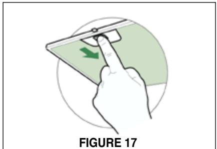
When "FF" message appears on the LED screen, the metal grease filters need to be washed in the dishwasher (SEE FIGURE 17 for removal instructions). To reset the metal grease filter alarm and the charcoal filter saturation alarm, turn off the motor and lights. Next, press and hold the 24 hour button "E" until the filter message disappears.
Charcoal Filter Information
The charcoal filters should be replaced (as indicated in FIGURE 7 on page 8) when the "EF" message appears on the LED screen or at least every 4 - 6 months depending on heavy usage. The alarm only comes on when the motor is turned on.
Charcoal Filter Alarm Activation
The filter alarm has to be activated in order to use with ductless installations which use charcoal filters. The alarm can be activated upon installation or at a later time. To activate or deactivate the alarm turn off the motor and lights, and disconnect the hood from the power source. Press and hold the "B" button while reconnecting the power source. Two rotating rectangles will then show on the LED screen and within 3 seconds press and hold the "B" button again, the LED screen shows a confirmation of the chosen setting below: "EF" flashes twice - Charcoal filter saturation alarm ENABLED "EF" flashes once - Charcoal filter saturation alarm DISABLED Repeat the process if you want to change the chosen setting, ie if the filter alarm is disabled, repeat the above paragraph to enable. Once finished with the activation / de-activation, again unplug and plug in the power source to return to normal hood function.
Cleaning
The mesh grease filters should be cleaned frequently in hot detergent solution or washed in the dishwasher. Stainless steel cleaner should be used on stainless rangehoods. Abrasives and scouring agents can scratch stainless steel finishes and should not be used to clean finished surfaces.
Replacing the Lamps
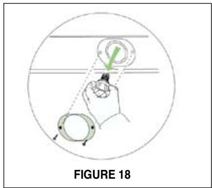
Before attempting to replace the lamps, make sure that the light switch is turned off. Remove the 2 screws (as indicated in FIGURE 18) that hold the light support and gently pull the support down from the hood. Remove the lamp from the light support and replace with new lamp. Replace the light support and fix it into place with the 2 screws.
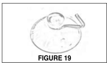
An alternative method to replace the lamps is to use a 1 1 / 4" suction cup (FIGURE 19). Attach the suction cup to the bulb and pull firmly down on the bulb and replace with a new lamp.
Remote Control
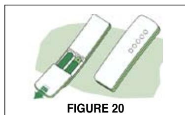
The rangehood can be controlled using the optional remote control which has the control layout (indicated in FIGURE 16 on the previous page). The remote uses alkaline AAAtype batteries. To replace the batteries, remove the cover by removing the screw and sliding off the cover (as indicated in FIGURE 20). Do not place the remote control close to heat sources.
FABER WARRANTY & SERVICE (SAVE FOR YOUR RECORDS)
All Faber products are warranted against any defect in materials or workmanship for the original purchaser for a period of 1 year from the date of original purchase. This warranty covers labor and replacement parts. To obtain warranty service, contact the dealer from whom you purchased the rangehood, or the local Faber distributor. If you cannot identify a local Faber distributor, contact us at (508) 358-5353 for the name of a distributor in your area.
The Following is not covered by Faber's warranty:
- Service calls to correct the installation of your range hood, to instruct you how to use your range hood, to replace or repair house fuses or to correct house wiring or plumbing.
- Service calls to repair or replace range hood light bulbs, fuses or filters. Those consumable parts are excluded from warranty coverage.
- Repairs when your range hood is used for other than normal, single-family household use.
- Damage resulting from accident, alteration, misuse, abuse, fire, flood, acts of God, improper installation, installation not in accordance with electrical or plumbing codes, or use of products not approved by Faber.
- Replacement parts or repair labor costs for units operated outside the United States or Canada, including any non-UL or C-UL approved Faber rangehoods.
- Repairs to the hood resulting from unauthorized modifications made to the rangehood.
- Expenses for travel and transportation for product service in remote locations and pickup and delivery charges. Faber range hoods should be serviced in the home.
Record Your Information Below:
Serial #:
Date of Purchase:
OUTILS NÉCESSAIRES À L'INSTALLATION
DIMENSIONS DE PRODUIT
DOS
CÔTE
AVANT
DESSUS
GLOBAL
DUCTED INSTALLATIONS
INSTALLATIONS SANS CONDUIT


- READ AND SAVE THESE INSTRUCTIONS
- READ THESE INSTRUCTIONS BEFORE YOU START INSTALLING THIS RANGEHOOD
- LISEZ BIEN CETTE FICHE AVANT D'INSTALLER LA HOTTE
- Cold Weather installations
- WARNING
- ELECTRICAL REQUIREMENTS
- RÉGLEMENTS D'ÉVACUATION
- PARTS SUPPLIED FOR INSTALLATION
- PARTS NEEDED FOR INSTALLATION
- OPTIONAL ACCESSORIES AVAILABLE
- Glass Kit
- - Charcoal Filter Kit
- CFM reduction kit
- - Remote Control
- PERSONAL INJURY HAZARD
- CALCULATE THE DUCTRUN LENGTH
- PRODUCT DIMENSIONS
- DUCTED INSTALLATIONS
- PREPARE THE WALL FOR ALL INSTALLATIONS
- DUCTLESS INSTALLATIONS
- USE AND CARE
- USE AND CARE CONTINUED
- For Best Results
- Grease Filter and Charcoal Filter Alarm Reset
- Charcoal Filter Information
- Charcoal Filter Alarm Activation
- Cleaning
- Replacing the Lamps
- Remote Control
- FABER WARRANTY & SERVICE (SAVE FOR YOUR RECORDS)
- The Following is not covered by Faber's warranty:
- Record Your Information Below:
- OUTILS NÉCESSAIRES À L'INSTALLATION
- DIMENSIONS DE PRODUIT
- INSTALLATIONS SANS CONDUIT
Brand : FABER
Model : CYLINDRA
Category : Range hood