
LINE 600 - Kitchen hood FALMEC - Free user manual and instructions
Find the device manual for free LINE 600 FALMEC in PDF.
| Product type | Cooker hood |
| Brand | FALMEC |
| Model | LINE 600 |
| Width | 600 mm |
| Depth | 300 mm (estimated) |
| Minimum height under hood | 65 cm |
| Power supply | 220-240 V ~ 50/60 Hz |
| Number of speeds | 4 (including 1 intensive timed 15 min) |
| Lighting | Halogen lamp 20 W max, 12 V, G4 base |
| Installation type | Wall or ceiling (island) |
| Extraction function | Yes (external ducting) |
| Recirculation function | Yes (with activated carbon filters) |
| Anti-grease metal filters | Dishwasher or hand washable (monthly) |
| Activated carbon filters | Replace every 3-4 months (depending on use) |
| Controls | Push buttons + optional remote control |
| Timer | Automatic shut-off after 15 minutes |
| Filter saturation indicator | Light alarm (red indicator) after approximately 30 hours of operation |
| Main material | Stainless steel |
| Approximate weight | 15 kg |
| Warranty | Manufacturer's warranty (see conditions on the back of the manual) |
Frequently Asked Questions - LINE 600 FALMEC
User questions about LINE 600 FALMEC
0 question about this device. Answer the ones you know or ask your own.
Ask a new question about this device
Download the instructions for your Kitchen hood in PDF format for free! Find your manual LINE 600 - FALMEC and take your electronic device back in hand. On this page are published all the documents necessary for the use of your device. LINE 600 by FALMEC.
USER MANUAL LINE 600 FALMEC
INSTRUCTIONS BOOKLET
Dear Sir/Madam, congratulations!
You have purchased a prestigious range hood of guaranteed quality. For best results, we suggest that you carefully follow the operating and maintenance instructions provided in this booklet; in addition, to order spare charcoal filters, use the special coupon on the cover.
NEW FIXING SYSTEM WITH MAGNETS
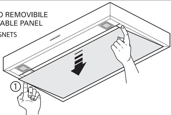
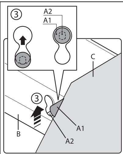
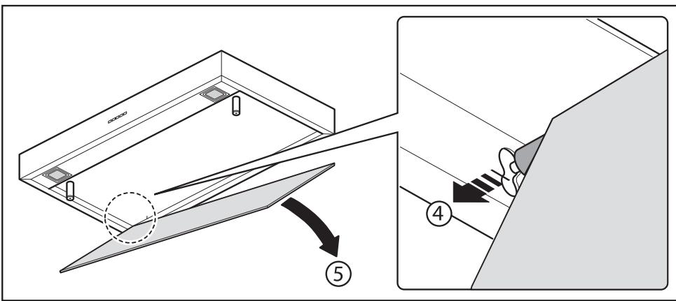
Fig. H3
MIRABILIA PARETE/WALL
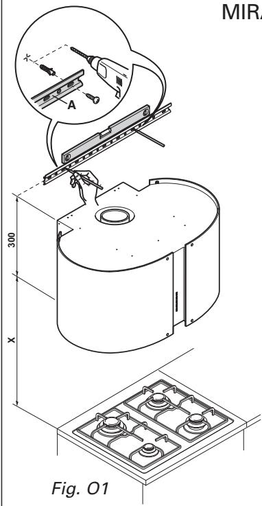
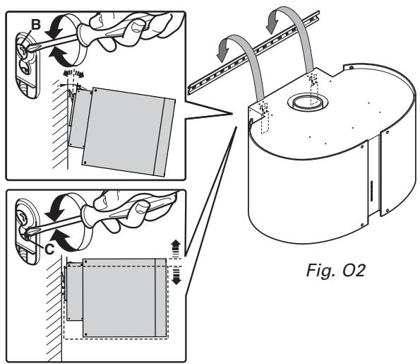
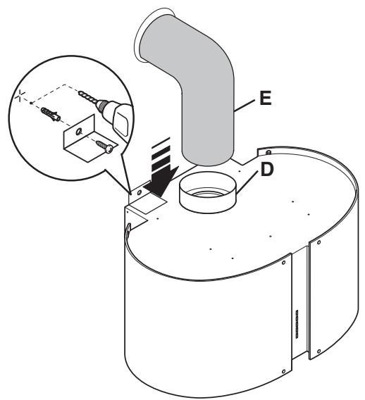
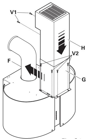
Fig. 04
Fig. 03
ISTRUZIONI MONTAGGIO/SMONTAGGIO VETRIMOUNTING INSTRUCTIONS FOR THE GLASSES
MIRABILIA 67 - MIRABILIA 97
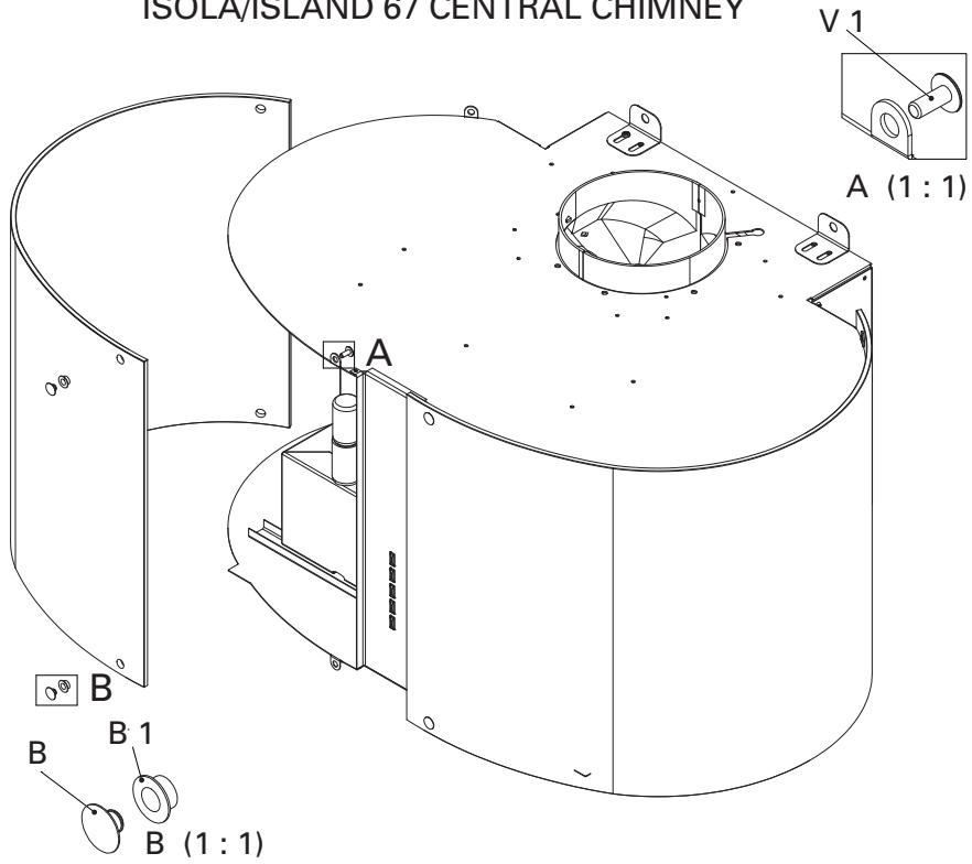
ISOLA/ISLAND 67 CENTRAL CHIMNEY
MIRABILIA ISOLA/ISLAND 85
Fig. 05
MIRABILIA ISOLA/ISLAND 85 ISOLA/ISLAND 67 CENTRAL CHIMNEY
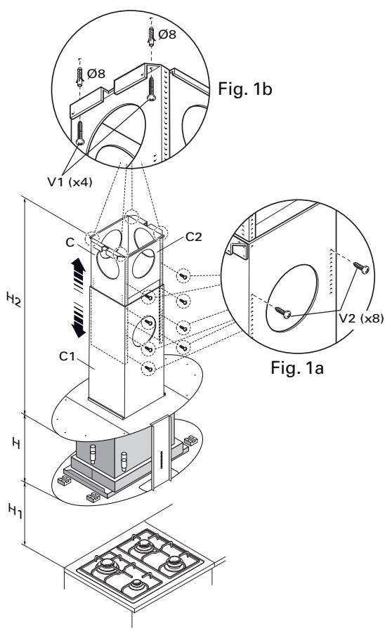
Fig. 1
$$ \mathrm {H} 1 = 6 5 0 \mathrm {m m} (2 5, 6 ^ {\prime \prime}) $$
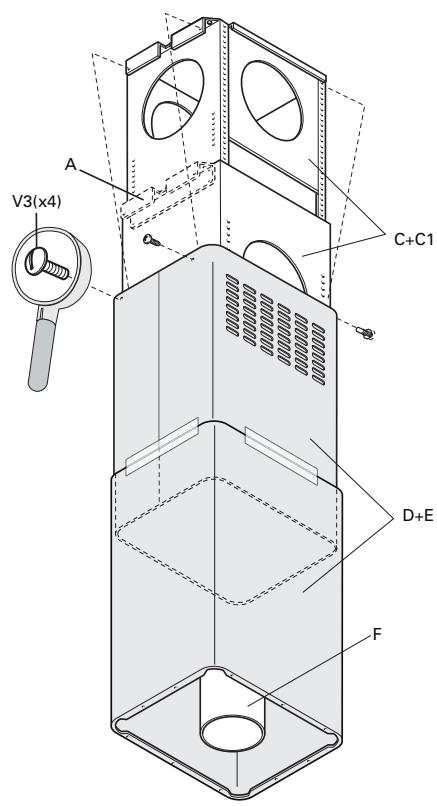
Fig. 2
MIRABILIA ISOLA/ISLAND 85 - ISOLA/ISLAND 67 CENTRAL CHIMNEY
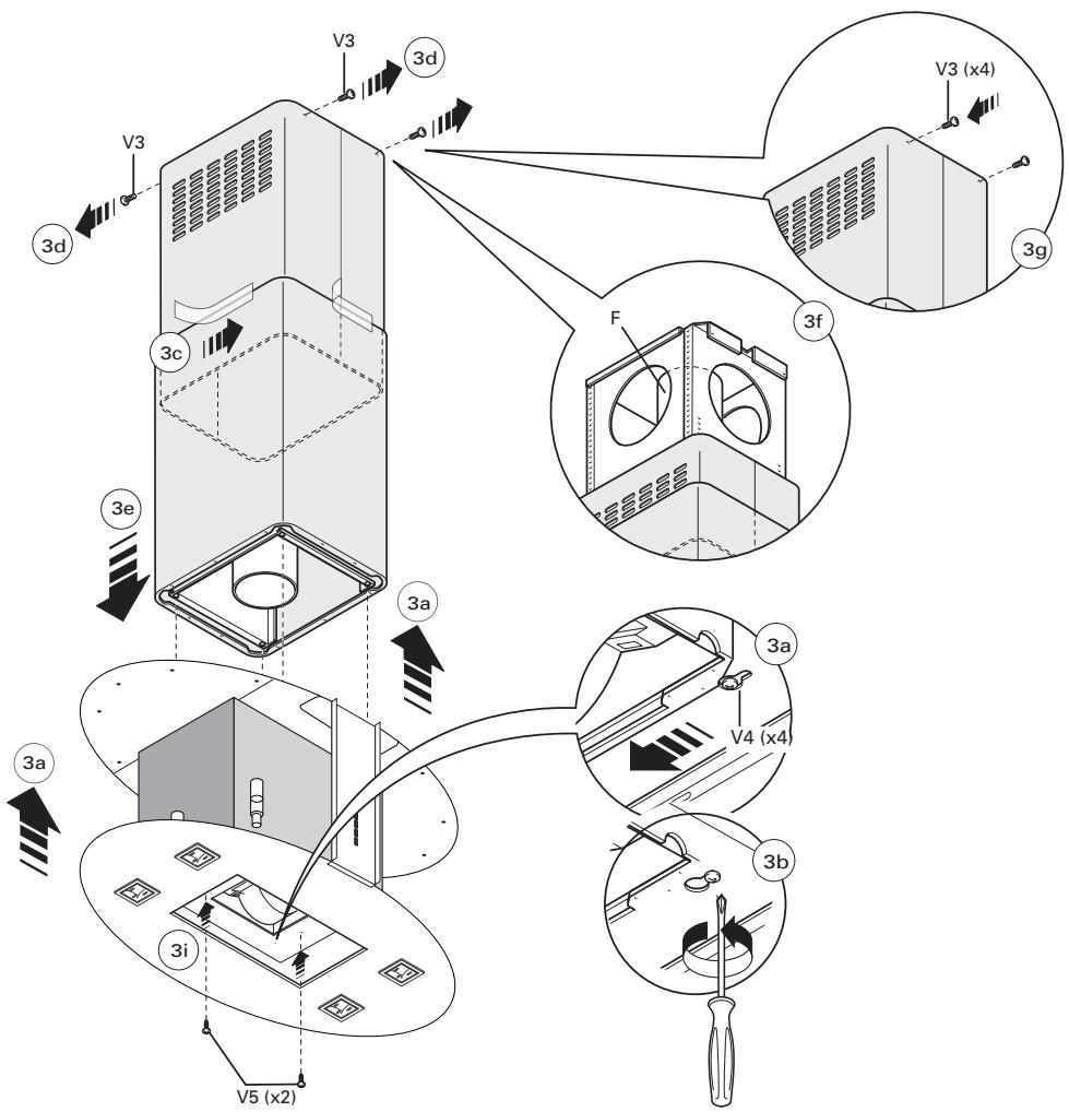
Fig. 3

AVVERTENZE


Square halogen light
This instruction booklet must be kept together with the appliance for future reference. If the appliance is sold or consigned to other parties, check that the booklet is supplied with it, to ensure that the new user has the correct information on the operation of the range hood and is aware of the warnings. These warnings have been provided for the your safety and the safety of others. As a result, please read them carefully before installing and operating the appliance.
This appliance is not intended for use by young children or infirm persons unless they have been adequately supervised by a responsible person to ensure that they can use the appliance safely. Young children should be supervised to ensure they do not play with the appliance.
The appliance must be installed by qualified personnel, in accordance with the standards in force. If the supply cord is damaged, it must be replaced by the manufacturer, its service agent or similarly qualified persons in order to avoid a hazard. Any modifications that may be required to the electrical system for the installation of the range hood must only be made by qualified electricians.
It is dangerous to modify or attempt to modify the characteristics of this system. In the event of malfunctions or if repairs are required to the appliance, do not attempt to solve the problems directly.
Repairs performed by unqualified persons may cause damage. For all repair and other work on the appliance, contact an authorised service/spare parts centre.
Always check that all the electrical parts (lights, exhaust device), are off when the appliance is not being used. Read the entire instruction booklet before performing any operations on the range hood.
The range hood must only be used for the exhaust of cooking fumes in home kitchens. The manufacturer disclaims all liability for any other use of the appliance.
The maximum weight of any object placed above the hood, or hung to it (if possible) must not exceed 1,5 kilos. After installing the stainless steel hood, clean it in order to remove any residue of the protective glue, and stains of grease or oil. The manufacturer recommends its cleaning cloth available for purchase. The manufacturer accepts no liability in case of damage caused by the use of different detergent types.

TECHNICAL SPECIFICATIONS
The technical data pertaining to the electric appliance The technical specifications of the appliance are shown on the rating plates located inside the range hood.
(Section reserved for qualified installers of the range hood)
The distance between the hob and the lowest part of the rangehood is normally at least 65~cm (see figure C1). This distance is measured in the lowest part of the rangehood not operating at safety voltage. Based on this detail provided by European Standards, the distance may be reduced in some models as specified in the general catalogue. If the instructions for installation for the gas hob specify a greater distance, this has to be taken into account.
In the outside exhaust version, the diameter of the fume discharge duct must be no smaller than the range hood connection.
In the horizontal sections, the duct must slope slightly (around 10% ) upwards, so as to better convey the air outside of the room.
Avoid using angled pipes, make sure that the pipes are at least of the minimum length.
Comply with the current regulations on air discharge into the atmosphere. If a boiler, stove, fireplace, etc. that uses gas or other fuels is being used at the same time, make sure the room where the fumes are extracted is well ventilated, in compliance with the current regulations.
Mounting instruction: see section "O" of the booklet.

ELECTRICAL CONNECTIONS
(Section reserved for qualified installers)
WARNING!
Before doing any work inside the range hood, disconnect the appliance from the mains power supply.
Check that the wires inside the range hood are not disconnected or cut; if this is the case, contact your nearest service centre. The electrical connections must be performed by qualified personnel.
The connections must be performed in compliance with the legal standards in force. Check that the relief valve and the electrical system are able to support the load of the appliance (see the technical specifications in point B).
Some types of appliance are supplied with a cable without plug; in this case, "standardised" plugs must be used, keeping in mind that:
- the yellow-green wire must be used for the earth,
- the blue wire must be used for the neutral,
- the brown wire must be used for the phase; the cable must not come into contact with hot parts (over 70^ ).
- fit a plug that is suitable for the load to the power cable, and connect it to a suitable power outlet.
For appliances that come supplied with cable and plug please ensure they are plugged into a circuit suitable for this appliance.
Please refer to a qualified person. (See technical specifications in point B).
The manufacturer declines all liability if the safety standards are not observed.

RANGE HOOD WITH OUTSIDE
DISCHARGE (exhaust)
In this version, the fumes and steam from the kitchen are conveyed outside through an exhaust duct.
The exhaust conveyor that protrudes from the upper part of the range hood must be connected to a duct that carries the fumes and steam outside. In this version, the charcoal filters, if fitted, should be removed; to do this, see the instructions in point F. There must be adequate ventilation of the room when the range hood is used at the same time as appliances burning gas or other fuels, according to the standard.
Deviation for Germany:
When the range hood and appliances supplied with energy other than electricity are simultaneously in operation, the negative pressure in the room must not exceed 4 Pa (4x10 E-5 bar).

RECIRCULATING RANGE
HOOD (with filter)
In this version, the air passes through charcoal filters for purification, and is then recirculated back into the kitchen.
Check that the charcoal filters are fitted to the motor, and if not, install them as described in the instructions in point H.
If the hood is of filtering type, remove the non-return valve fitted at the motor's outlet.

For maximum efficiency, the third speed should be used when there are strong odours or a lot of steam, the second speed in normal conditions, and the first speed for keeping the air clean with minimum energy consumption. The range hood should be switched on when starting to cook, and left on until the odours disappear.

OPERATION
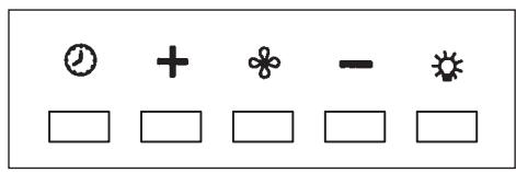
ELECTRONIC CONTROL PANEL
Light pushbutton

- ON: light on (the pushbutton is lit);
- OFF: light off;
Dimmer with keyboard integrated functions: with motor off and prolonged pressing of keyboard light key (2 seconds), access is gained to the amend atmosphere light intensity (incandescent or LED lamp). By acting on the + and - keys, light intensity is adjusted. With motor started, the prolonged pressing of the key, switches the atmosphere light on or off.
Pushbutton -
Press to reduce motor speed
Speed 1, 2 and 3 are indicated by the number of LEDs that light up (excluding the light and the timer LEDs).
Pushbutton +
Press to increase motor speed
Speed 1, 2 and 3 are indicated by the number of LEDs that light up (excluding the light and the timer LEDs). (In the 4-speed version the pushbutton + blinks. The fourth speed remains on for a set duration of time. After 15 minutes the motor returns to the third speed).
Mode pushbutton
Function: it turns hood motor on and off.
The function "desired speed" enables to start the motor at the speed that was selected before the hood was last turned off.
Optional: version with remote control (some versions only).
WARNING:
Install the hood away from sources of electromagnetic waves, as these could affect the correct operation of the electronic system.
Maximum operating distance: 5 metres. The maximum operating distance could be less than 5 metres in case of electromagnetic interference by other equipment.
Light pushbutton on remote control: light on/off.
- and + pushbutton: increase/decrease speed (to start the motor press either the + or the - pushbutton).
Timer pushbutton: see instructions below.
Timer and 'filter clogged' alarm pushbutton
-
This function allows the automatic turning off of the hood after running for 15 minutes at the speed previously set (the pushbutton shows a flickering light).
-
After about 30 hours of running the pushbutton indicates the need for washing the metal filters (the pushbutton shows a solid red light). To disable the alarm press the pushbutton for a few seconds until the red light turns off. Then turn the hood off and on again to check that the alarm has disappeared.

FILTERS REMOVING AND REPLACING'S INSTRUCTIONS
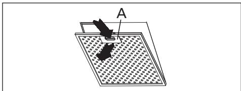
1. METAL FILTERS
Open the panel (see fig. H3). Use handle A to remove the metal grease filter.
2. CHARCOAL FILTERS
To replace the charcoal filters, proceed as follows: remove the metal filters as described above. The two filters located at the ends of the motor can now be easily accessed.
To install the new filters see picture.
In case of hood with the motor box the filter is located on the bottom part of the motor box.
To install the new filters see picture.
To order new charcoal filters contact the distributor/retailer.
VALID ONLY FOR ITALY: download the appropriate order form from: www.falmec.com (access the assistance drop-down menu).
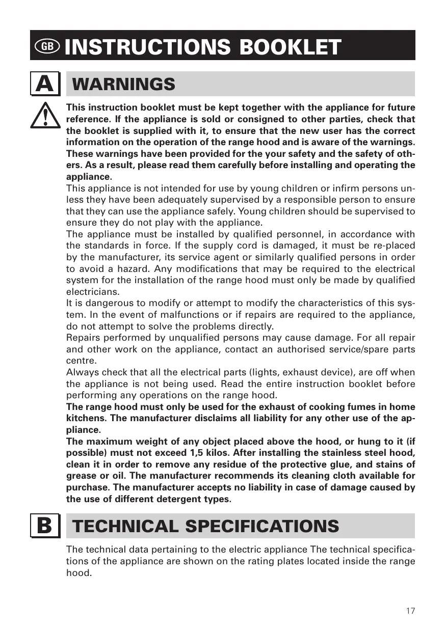
3. REMOVABLE PANEL
Follow the instructions on fig. H3 to remove the panel.

LIGHTING ASSEMBLY AND REPLACEMENT
SPOTLIGHT
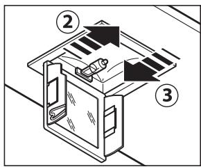
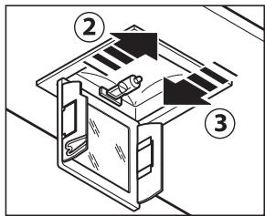
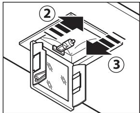
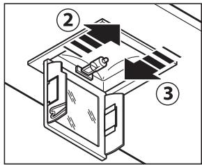
How to replace a square halogen light:
a) Check that the equipment is disconnected from the power supply.
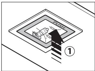
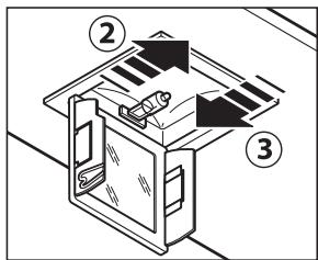
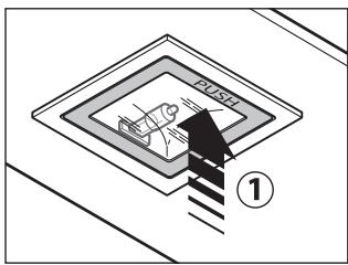
b) Open the panel completely till 90^ (see figure) pressing the PUSH button
c) Replace the lamp with a similar one (halogen, max 20 W, 12 Volt, G4 connection).
d) Close the panel. If the panel does not close correctly repeat the operation at point b.
Square halogen light
GLASS LIGHTING
To replace the incandescent lamp:
1) ensure the hood is disconnected from the electric mains;
2) remove the decorative glass (see sec. O);
3) replace the lamp with one of the same model (max. 25W);
4) re-mount the glass (see fig. 05).
In case of hoods with LED lighting, the replacement of the luminous body can only be carried out by specialised staff and with original spare parts.
WARNING: Do not remove the glass if the glass LED lighting is on.

MAINTENANCE AND CLEANING
Constant maintenance ensures the correct operation and efficiency of the appliance over time. Special attention should be paid to the metal grease-trapping filters and the charcoal filters. Frequent cleaning of the filters and their supports will ensure that fats and grease do not accumulate on the range hood, with the consequent risk of fire.
1. METAL GREASE-TRAPPING FILTERS
These trap the fat and grease particles suspended in the air, and therefore should be washed every month in hot water and detergent, without bending them. Wait until they are completely dry before repositioning them.
To remove and replace these filters, see the instructions in point H1. This operation should be performed at regular intervals.
2. CHARCOAL FILTERS
These trap the odours present in the stream of air that passes through them. The air is purified by passing a number of times through the filters and being recirculated into the kitchen. The charcoal filters cannot be cleaned, and should be replaced on average every 3-4 months (according to use). To replace the charcoal filters, see the instructions in point H2.
3. CLEANING THE OUTSIDE OF THE APPLIANCE
It is advised to clean the external hood surfaces at least every 15 days in order to avoid that oily or greasy substances affect the steel surfaces.
The aside of the range hhod should be cleaned using a damp cloth and neutral liquid detergent or denatured alcohol.
In case of fingerprint-less finish (fasteel) clean only with water and neutral soap using clean with a soft cloth, rinse and wipe dry thoroughly. Do not use products that contain abrasive substances, rough cloths or cloths specifically designed for cleaning steel. Using abrasive substances or rough cloths will inevitably damage the finish of steel. The steel surface will be irrevocably damaged if the instructions above are not complied with.
Keep these instructions together with the instructions for use of your hood.
The manufacturer accepts no liability for any damage caused by non-compliance with the instructions above.
4. CLEANING THE INSIDE OF THE APPLIANCE
The electrical parts or parts of the motor assembly inside the range hood must not be cleaned using liquids or solvents.

Do not use abrasive products. All the above operations must be performed after having disconnected the appliance from the mains power supply.

The electrical system features an earth connection in compliance with international safety standards; furthermore, it is compliant with the European standard for electromagnetic compatibility.
Do not connect the appliance to flues (from boilers, fireplaces, etc.). Make sure the mains voltage corresponds to the values on the rating plate located inside the range hood. The minimum safety distance between the cooktop and the range hood must be at least 65~cm .
Never cook on "open" flames under the range hood.
Check deep-fryers during use: superheated oil may be flammable.
- Ensure there is adequate ventilation of the room when the rangehood is used at the same time as appliances burning gas or other fuels.
- Do not flambe under the rangehood
- The exhaust air must not be discharged into a flue which is used for exhausting fumes from appliances burning gas or other fuels.
- Ensure that all regulations concerning the discharge of exhaust air have been fulfilled before you use the appliance.

Before performing any cleaning or maintenance operations, disconnect the appliance by unplugging it or using the main switch. The manufacturer disclaims all liability for any damage that may be directly or indirectly caused to people, things and animals due to the failure to follow all the instructions provided in this booklet and above all the warnings relating to the installation, operation and maintenance of the appliance.

WARRANTY
The new equipment is covered by warranty.
The warranty conditions are provided by the distributor.

The manufacturer is not liable for any inaccuracies in this booklet resulting from printing or transcription errors. The manufacturer reserves the right to modify its products as it considers necessary or in the interests of the user, without compromising their essential safety and operating characteristics.

HOOD INSTALLATION
O1 - INSTRUCTIONS FOR WALL-MOUNTED MIRABILIA HOODS
Phase 1
- Place the support bar next to the wall (A-Fig. O1), at a height above the cooktop which corresponds to X + 300mm .
- With a spirit level check that the bar is horizontal. Mark a point at each end of the bar.
- Drill the holes, fit 2 8mm expansion joints and screw in the bar.
Phase 2
-
Fit the hood to the support bar (Fig. O2).
-
Adjust hood alignment with the relevant screws: The top screw (B) adjusts the distance from the wall. The bottom screw (C) adjusts the vertical sliding movement.
Phase 3
- To prevent the hood from detaching if pressure is exerted from beneath, secure it to the wall with the brackets supplied (fig. O3).
- Fit pipe/hose (E) into (D).
Phase 4
- Slide the extension (H) into (G) till the desired height.
- When the extension is at the desired height, screw it onto the chimney with the screws supplied (V1);
- Lock the chimney + extension onto the hood with 6 V2 screws.
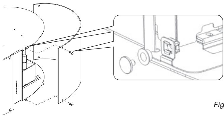
- Fit the glass panels (fig. O5).
O2 - INSTRUCTIONS FOR MIRABILIA ISLAND 85/ISLAND 67 CENTRAL CHIMNEY
Phase 1
- Identify the desired height (H1=65) for the positioning of the hood.
- Slide the lattice-works (C) and (C1) to the desired height (H2), then block them with the 8 self-threading screws (V2) (Fig.1a).
- Fasten the lattice-work (C) to the ceiling using the four expansion plugs and relative screws(V1) (Fig.1b).
Phase 2
- Insert the extension on the flue and fasten them to each other with masking tape (Fig. 2).
- Fasten the flue-extension assembly (D+E) to the lattice-work (C) with the 4 M4 metric screws (V3) inserted in the existing holes without tightening them completely (Fig. 2).
- For suction version: identify the optimal height for the rigid or flexible exhaust pipe (F) and connect it to the motor connection.
Phase 3
- Raise the hood, hooking it onto the 4 M5 metric screws (V4) pre-tightened to the lattice-work (C) (center the 11 holes on the slot of the inner liner and move it laterally)(Fig. 3a).
- Completely tighten the 4 M5 screws (V4) (Fig. 3b).
- Remove the masking tape (Fig. 3c), remove the four M4 metric screws (V3) previously tightened onto the lattice-work (Fig. 3d) and slide the flue-extension assembly downwards. (Fig. 3e).
- Connect the pipe to the connection of the ceiling discharge hole. (Fig. 3f).
- Make electrical connections only after having removed electrical power supply.
- Fasten the extension to the lattice-work (C) by means of the 4 M4 metric screws (V3), without tightening them completely(Fig. 3g).
- Block the extension completely to the lattice-work (C) by screwing down the 4 M4 metric screws (V3).
- Block the flue with the 2 self-threading screws (V5) (Fig. 3i).
- Use the extension support elements(A) (Fig. 2) only if the upper lattice-work is not used, or in the case of a false ceiling.
- Fit the glass panels (fig. O5).

HINWEISE

ELEKTRONISCHES BEDIENFELD
Lichtknopf
Square halogen light
Square halogen light
ECLAIRAGE DES VITRES
Square halogen light
MEPbI PPEIOCTOPOXHOCTN
OueHb BaxHo, YTO6bl DaHHoe PyKOBoDCTBO no 3KnIpyaTauHn XpaHInocsbBmecTe c aannapaTypoi dIy Bo3MOxHoi Heo6XoIMoCTn KOHCyIbTaUIN B6yduem.
Pnp npoajke npnbopa nnn nepeaue ero dpyromy nucy K npnbopy 6b3atelbno doJXHO npnlaTbc PyKOBODCTBO, T06bl HOBbI NOlb3OBaTeIb 6bl B Kypce TORO, KaK NOlb3OBaTbcB bItjKoN KaKne COOTBeTCTByIOUe MepbI npdeOCTOpOXHOCTH Heo6xOdmo Co6JIOnDaTb.
ДанhoePykoBoDcTBo6bIIOcoCTaBJIeHOДЯ6e3OJaNacHocTnKaBaWe,Tak NOKpykaIoUxN,No3ToMу npocmBac BHNMaTeJbHo C Hm O3HaKOMtbcr NepeD yCTaHOBKoI n 3KnJIyatauNei npnbopa.
IeTAM I6OJIbHbIM IIOJAM pa3peWaeTcI N0JIb3OBaTbcra npu6Opom IINUb IOnd aIeKBAthbIM KOHTPOEm OTBETCTBeHHbIX IINU, KOTOpbIe MOryT OBeCneuBaTb 6e3oNaChoe IcNoJIb3OBaHne npu6opa.
OTBETCTBEHHOMy IINuY Heo6xoIIMO CJIeIITb, YTO6bl DeTn He Irpaln c npIbOpom.
Pa60tbl no yctaHOBKe DoJXHbI npoBOINTBcR KOMnTeHTHBIMn KBaJIncfNpOBAHHbIMn CneuaJIncTAmN cOrlaCHO DeNCTBYUOUM HOpMaM.
JIIO6OE Heo6xOJIMoe IyYCTaHOBKn BbITJXKN N3MeHHe B 3JeKTPnueCKOM 6JIOKe D0JXHO OCyUeCTBJIbTcR ToJIbKO KOMIeTeHTbIM JINlOm.
I3MeHHeNe IJIN NONbITKa I3MeHEnHa xapaKTePncTnK npnbopa onaCHO! B cnyuae HeKOppeKTHoI pa60TbI BbITaJIcKn He nbITaJIteCb yCTpaHHTb HeNCnPpABHOCTb CAMOCTOReJIbHO.
Pemont, npoBeHbI HeKOMTeHTbIM IuOm, MoKeT Bbl3BaTb NOBpeJdeHn.
y6dntcb, yTO BHytpn BbITJxHOrO yCTpOcTBO H OTCoDHHbl N H NOBpKdHbI 3NkTpncKn npOBoDa; B cLnya BO3HNKHOBNH TaKnx CNTyaCNI CBxKNTcb C 6bnXaWIM CpBNCbM uHTpOM. DnBbINOHNH NkTpncKn COINHHN
6paTntcb K KBaJIHΦnIupOBaHbIM CπIaJIHCTam.
COnHHnD OJXHbI 6bITb IPOUN3BHN B COOTBTCTBn C DnCTBYUHmM 3aKoHOaTlbCTBOM. YbNTcb, YTO ORpaHnHTlbHbI npDOxpaHnTlN IN 3JIKTPOO6OpyDoBaHUMOryT BblpXaTb HarpY3Ky OT npN6opa (CM. 3TNKTky C TXHnCKIMN XapaKTPncTnKaMn, corLnacHo nyHKTy B). HkOtporbl np66opbl MOryT 6bITb OChauHbI shypom 63 BnKn; B TaKOM cInCyHa nCnObn3yma BnJa DOJXHa
6bITb "CTaHdapTHoro" TnA c yTOM TORO, YTO:
- JNTO-3HbI NPOBOD OJXH INCNOJB3OBaTbcra 13a3MnHna,
- rony6oI npOBOD oJxH NcOJIb3OBAtbcra Iy HITpaJIbHO rnpOBoDa,
- KOpuHbI npoBOd DoJXH NcNoJIb3OBAtbc Da Jpa3bl, UHyp HdoJXH KaCaTbcHaRpTbIX qactn, ImIOxN TmnpaTy p601 70^
- yCTaHOBnT Ha shHyp 3JIkTpOnItaHnB BnIKy, npriOndHyIO dIpy3Kn, n BCTaBBt B 3aunTHyIO BnIKy.
Pn H6xOJIMOCTN nprMOro NODKJIIOUHnN K CTN H6xOJIMO pa3MCTNTb MxNy npnbopom n CTbIOMHORONOLpHbIM MaHHTOTPMUCKn IpkJIIOuATNb C MNHMaJIbHbIM OTKpbITmMkNy KOHTaKTAMN 3 MM, paccHTaHHbI Ha Harpy3Ky I OTBaIOUm dNCTBYIOUHm HopMa. XJTO-3JIbI pOBoD 3a3MlHnI HdoJIxH npbbiBaTbcrnpKJIIOUaTIm.
IIOIOKJIIOUHnI np6Opa K CTN 3IKTpOnnTaHnYbNTcb, YTO:
- HaprxkHn CTN PHTAHNO COOTBTCTByT yKa3aHHOMy Ha 3TNKTK C TXHNUCKMn XapaKtpncTKamn.
-3a3MJIH NФФКТИВНО И BbIINHNO ПраВЛьНО.
-ЛИИЯ 3ДКТрОПИТАИЯ OСHAЦHA 3ФФКТИВHBIM 3a3MЛHIM NO ДИСТBYЮЦМ HOPMaM. - INCNoJIb3yMbI po3TKa IIN MHOrONoJIocHbI npKJIouaTJIb IIGKO DoCTyHbI npN yCTaHOBnHHOM npi6Op.
ПюиЗВоДиТьН HCT НИКаКОЛ OTВТСВHOCTN B CNYa, сн HOpMbI 63OnaChOCTn H co6JIIOJaIOTcY.

E BbITJXHOE YCTPOICTBO C BbIBPOCOM BO3dUXA HAPXXU
B 3ToMmDn DbIM n nap OT roTobKn Bbl6paCbIbAOTc HapJy cy3 Tpy6y.
Tpy6a IJRA BbIbpoCa, KOTOPaR BbICTyNaT n3 BxHn qACTn BbITJXKN DoJXHa 6bITb COINHc Tpy6o, KOTOPaR BbIOdNt DbIM n Nap BH NOMUHN, PNC.
B daHHo moJIn CHImaIOTc qnJIbTpbl Ha aKTbUropOBaHHom yI, cNIO OHYCTaHOBJHb; KaK OHN CHImaIOTc, CM. NyHKT F. EcN KyXOHHa BbITaKKaNCNoJIb3yTcO ndHOBpMHNO nДЯ dpyrnx npnbOpOB, pa60taIOxH ha ra3yIIN dpYROM TOnJIHB, POMuH NdoJIxHo IMMb BO3MOxHOCt b DOCTaTOCHORnpOBTpBuHaH.

BbITJXHOE YCTPOIcTBOC PEUNPKUJIaIeN BO3dYXA (cФиЛьТрацn)
B 3ToI MoJIn BO3DyX npOxOuIT Up3 qNlBtpbl C aKTHBnPoBaHHbIM yTJIM, IOnuTaCn BO3BpaUaTcB NOMUHN KYXHN.
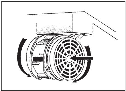
Y6nTcB, YTO yOrbHbI qInbTpbl yCTaHOJIbHbI Ha MOTop, pnc. 6, B npOTNBOM Cnya yCTaHOBNT IN, KaK yKa3aHO B nyHKT F nHCTpyKUIN.
IyuyuHnX npn HnHbIX 3anaxOB nN 60nbOro KOIncTba npa, BTOpyo CKOpocTB HopMaJIbHbIX ycNoBnx, npByIO CKOpocTB JIA ONUCTKN BO3dyxa npn Hn3KOM paCXoIOBaHHn 3JKTPO3Hpnn.
PKOMHdyTCB KBIIOUaTb BbITXK Ky, KOrDa Bbl HauHHAT RTOBHTb N OCTaBnTb pa6oTaIoJ Do nC3HOBHn CnIbHbIX 3anaxOB.
KHONK C 3JEKTPOHbIM YNPABJIeHnEM
Klabnua ocbeuehenra

-ON:ocBeueHHeBnOeHo(KHOnIkaCBeTntcra)
- OFF: ocBeueHneBbIKIOueHo;
ДИММЕ CO BCTPOEHHbIMN B KlaBnATpyФуHKUHMM npn BblKJIIOUeHOM DBrIaTeIe n npoJOnKInTeIbHOM HaxaTIN (2 cekyHdbI)Ha KHOKNYOCBeIeHnHa KlaBnAtype,MOxHO BoITN B pexIM N3MeHEnn INHTeHCNBHOCTN OCBeIeHnOKpyKaIOSe aTMocOepbl (JaMn HakAJINBaHN IINCBETOIOIOB).Haxmam Ha KhoKn + -,perynpyeTcN INHTeHCNBHOCTbOCBeIeHn. Pnp BKIOHcHOM DBrIaTeIe n npoJOnKInTeIbHOM HaxaTINHa KHOKN, npoICXODNT BkIOUeHne IIN BblKIOUeHne OCBeIeHn OKpyKaIOSe CpeDbI.
KnaBnsa -
KnaBnHa ocBeHHeHn Ha npIbTe: CBET BkN./BbIK. (on/off).
KnaBnla - e + yMeHbWeHne/YBeIuYeHne cKOPOCTn (Для 3anycka MoTopa MoXHO HaKaTb KaK KnaBnUy +, TaK N KnaBnUy -).
KnaBnua TaMepa:cm. HnKe INHcTpkyuIIO.
KnaBnua TaMepa u NacbIeHn qNbTpO

Square halogen light
OCBEUHNE CTEKOJI
ДяЗаменилампьHaKaJIиВaHЯ:
1) y6eɪntbca B TOM, yTO BbɪTjʌkka OTKJIʊchæHa OT ᵋJIeKtpocetɪn;
2) ydaunTb deKopaTnBhIe cTeKna (cm. pa3d. O);
3) 3aMeHnTb lamNoUky Ha taKyu Jx Me MoJeIb, KaK BOpuHaJIe, (MaKc. 25 Br);
4) yctaHOBNTb Ha MeCTO CTekla (cM. pnc. O5).
B clyae BbTjKKn CO CBEToIONoHbIM OCBWeHneHem, 3aMeHa CBeTaIeOc Tela MoKeT npOn3BOdntbcr ToIbKO KBaJInΦuNpObaHHbIM CneuaJIncTOM N ToIbKO HaOpUInHaIbHbIe ΦnpMeHHbIe 3anYactn.
PNEyPPEKDEHNE: He ydaJIaTb CTekla npn BkIIOUeHHOM CBeToNDHOm OCbeueHn CTekoJ.

ЧИСТКА И YXOD
CBoBmHbI yXoI rapaHTpyT xopoOsyu pa60Ty n 60JIbwoi cpoK cnyk6bl. Oco6HHo BnMaHn Ho6xOdmo YdIaTb MtaJIbUcKm fNJIbTpam dIy 3axBaTa Jnpa n fNJIbTpam C aKTbUpOBaHHbIM yrJIM, DInCTBNTlbHO, qacta OunchKa fNJIbTpOB n MCT IN KpIINHra rapaHTpyT, yTO B BBITJHK H Co6UpaTcR XnP, KOtOpBI ONACH I3-3a IIRKOCTN BO3ROPAHNA.
1. METAJIINUÇECKNE ΦΙΝΙbTPblДЛЯ 3ADEPЖAHNY XNPA
PpHa3HaHbI dIy yIaBnBaHn yacTnq Knpa, pKOMHdyTc Mblb pa3 McaC B BOI n C MOIOUIM CpDCTBOM, H npri6a Ix. Do yCTaHOBKn DOXJNTcb Ix NOJIHO R BblcIxAHN. DnI TORO YTO6bI ChrTb cINbTp n yCTaHOBnTb Ha MCTO CM. INHCTpyKuN, nyHK T. PKOMHdyTCs pryIaRHO BblONHry 3Ty onpaIIO.
FILTRY INSTRUKCJE WYJMOWANIA I WYMIANY
1. FILTRY METALOWE

Square halogen light
