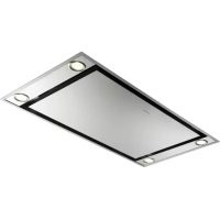
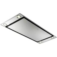
TRATTO ISOLA - FABER - Free user manual and instructions

Find the device manual for free TRATTO ISOLA FABER in PDF.

Page 2
View the manual : Français FR English EN
Manual assistant
Powered by ChatGPT
Waiting for your message
Product information

Brand : FABER

Model : TRATTO ISOLA

Download the instructions for your in PDF format for free! Find your manual TRATTO ISOLA - FABER and take your electronic device back in hand. On this page are published all the documents necessary for the use of your device. TRATTO ISOLA by FABER.

USER MANUAL TRATTO ISOLA FABER

READ AND SAVE THESE INSTRUCTIONS The Installer must leave these instructions with the homeowner. The homeowner must keep these instructions for future reference and for local electrical inspectors' use.

READ THESE INSTRUCTIONS BEFORE YOU START INSTALLING THIS RANGEHOOD WARNING: - TO REDUCE THE RISK OF A RANGE TOP GREASE FIRE: a) Never leave surface units unattended at high settings. Boilovers cause smoking and greasy spillovers that may ignite. Heat oils slowly on low or medium setting. b) Always turn hood ON when cooking at high heat or when flambeing food (i.e. Crepes Suzette, Cherries Jubilee, Peppercorn Beef Flambé). c) Clean ventilating fans frequently. Grease should not be allowed to accumulate on fan or filter. d) Use proper pan size. Always use cookware appropriate for the size of the surface element. WARNING: - TO REDUCE THE RISK OF INJURY TO PERSONS IN THE EVENT OF A RANGE TOP GREASE FIRE, OBSERVE THE FOLLOWING (*): a) SMOTHER FLAMES with a close-fitting lid, cookie sheet, or metal tray, then turn off the burner. BE CAREFUL TO PREVENT BURNS. If the flames do not go out immediately EVACUATE AND CALL THE FIRE DEPARTMENT. b) NEVER PICK UP A FLAMING PAN - You may be burned. c) DO NOT USE WATER, including wet dishcloths or towels - a violent steam explosion will result. d) Use an extinguisher ONLY if: 1) You know you have a Class ABC extinguisher, and you already know how to operate it. 2) The fire is small and contained in the area where it started. 3) The fire department is being called. 4) You can fight the fire with your back to an exit. (*) Based on “Kitchen Firesafety Tips” published by NFPA. ALL WALL AND FLOOR OPENINGS WHERE THE RANGEHOOD IS INSTALLED MUST BE SEALED. This rangehood requires at least 24" of clearance between the bottom of the rangehood and the cooking surface or countertop. This minimum clearance may be higher depending on local building code. For example, for gas ranges, a minimum of 30" is recommened and may be required. Overhead cabinets on both sides of this unit must be a minimum of 18" above the cooking surface or countertop. Consult the cooktop or range installation instructions given by the manufacturer before making any cutouts. LISEZ BIEN CETTE FICHE AVANT D'INSTALLER LA HOTTE AVERTISSEMENT - POUR MINIMISER LE RISQUE D’UN FEU DE GRAISSE SUR LA TABLE DE CUISSON : a) Ne jamais laisser un élément de la table de cuisson fonctionner sans surveillance à la puissance de chauffage maximale; un renversement/ débordement de matière graisseuse pourrait provoquer une inflammation et le génération de fumée. Utiliser toujours une puissance de chauffage moyenne ou basse pour le chauffage d’huile. b) Veiller à toujours faire fonctionner le ventilateur de la hotte lors d’une cuisson avec une puissance de chauffage élevée ou lors de la cuisson d’un mets à flamber (i.e. Crepes Suzette, Cherries Jubilee, Peppercorn Beef Flambé). c) Nettoyer fréquemment les ventilateurs d’extraction. Veiller à ne pas laisser de la graisse s’accumuler sur les surfaces du ventilateur ou des filtres. d) Utiliser toujours un ustensile de taille appropriée. Utiliser toujours un ustensile de taille adapté à la taille de l’élément chauffant. AVERTISSEMENT: - POUR PRÉVENIR LES BLESSURES EN CAS DE FEU SUIVRE LES RECOMMANDATIONS SUIVANTES (*): a) ÉTOUFFEZ LE FEU avec un couvercle métallique et fermez le brûleur. Si le feu ne s'éteint pas tout de suite, QUITTEZ LES LIEUX ET APPELEZ LES POMPIERS. b) NE TOUCHEZ JAMAIS UNE CASSEROLE EN FLAMMES. c) N'UTILISEZ JAMAIS DE L'EAU ou un torchon mouillé pour éteindre le feu - ce qui pourrait causer une explosion de vapeur. d) N'utilisez un extincteur que si: 1. Vous avez un modèle ABC et vous connaissez bien son mode d'emploi. 2. Le feu est petit et peu répandu. 3. Les pompiers sont déjà prévenus. 4. Vous avez une sortie derrière vous. (*) Basé sur la "cuisine Firesafety incline" édité par NFPA. TOUTE OUVERTURE DANS LE MUR OU LE PLANCHER À PROXIMITÉ DE LA HOTTE DOIT ÊTRE SCELLÉ Gardez 24 po. de hauteur entre le bas de la hotte et la surface de cuisson. Cette hauteur minimum peut être plus haute suivant le code municipal. Par exemple, les cuisinières à gaz peuvent requérir 30 po. de hauteur. Les armoires au-dessus de chaque côté devront être au moins à 18 po. au-dessus de la surface de cuisson. Consultez la fiche technique avant de découper les armoires. Version 02/12 - Page 1

VENTING REQUIREMENTS Determine which venting method is best for your application. Ductwork can extend either through the wall or the roof. The length of the ductwork and the number of elbows should be kept to a minimum to provide efficient performance. The size of the ductwork should be uniform. Do not install two elbows together. Use duct tape to seal all joints in the ductwork system. Use caulking to seal exterior wall or floor opening around the cap. Flexible ductwork is not recommended. If it is used, each foot of flexible ductwork used is equivalent to two feet of straight metal ductwork when calculating the ductrun length. Thus, a flexible elbow equals two standard elbows. Make sure there is proper clearance within the wall or floor for exhaust duct before making cutouts. Do not cut a joist or stud unless absolutely necessary. If a joist or stud must be cut, then a supporting frame must be constructed. FOR MORE SPECIFIC DUCTWORK INFORMATION, GO TO PAGE 4. WARNING - To Reduce The Risk Of Fire, Use Only Metal Ductwork.

Cold Weather installations An additional back draft damper should be installed to minimize backward cold air flow and a nonmetallic thermal break should be installed to minimize conduction of outside temperatures as part of the vent system. The damper should be on the cold air side of the thermal break. The break should be as close as possible to where the

vent system enters the heated portion of the house.

CAUTION: To reduce risk of fire and to properly exhaust air, be sure to duct air outside - do not vent exhuast air into spaces within walls or ceilings or into attics, crawl spaces or garages.

• Venting system MUST terminate outside the home. • DO NOT terminate the ductwork in an attic or other enclosed space. • DO NOT use 4" laundry-type wall caps. • Flexible-type ductwork is not recommended. • DO NOT obstruct the flow of combustion and ventilation air. • Failure to follow venting requirements may result in a fire.

ELECTRICAL REQUIREMENTS A 120 volt, 60 Hz AC-only electrical supply is required on a separate 15 amp fused circuit. A time-delay fuse or circuit breaker is recommended. The fuse must be sized per local codes in accordance with the electrical rating of this unit as specified on the serial/rating plate located inside the unit near the field wiring compartment. THIS UNIT MUST BE CONNECTED WITH COPPER WIRE ONLY. Wire sizes must conform to the requirements of the National Electrical Code, ANSI/NFPA 70 - latest edition, and all local codes and ordinances. Wire size and connections must conform with the rating of the appliance. Copies of the standard listed above may be obtained from: National Fire Protection Association Batterymarch Park Quincy, Massachusetts 02269

For residential use only.

This appliance should be connected directly to the fused disconnect (or circuit breaker) through flexible, armored or nonmetallic sheathed copper cable. Allow some slack in the cable so the appliance can be moved if servicing is ever necessary. A UL Listed, 1/2" conduit connector must be provided at each end of the power supply cable (at the appliance and at the junction box). When making the electrical connection, cut a 1 1/4" hole in the wall. A hole cut through wood must be sanded until smooth. A hole through metal must have a grommet. WARNING - TO REDUCE THE RISK OF FIRE OR ELECTRIC SHOCK, do not use this fan with any solid-state speed control device. WARNING - TO REDUCE THE RISK OF FIRE, ELECTRICAL SHOCK, OR INJURY TO PERSONS, OBSERVE THE FOLLOWING: A) Use this unit only in the manner intended by the manufacturer. If you have any questions, contact the manufacturer. B) Before servicing or cleaning unit, switch power off at service panel and lock the service disconnecting means to prevent power from being switched on accidentally. When the service disconnecting means cannot be locked, securely fasten a prominent warning device, such as a tag, to the service panel. CAUTION: For General Ventilating Use Only. Do Not Use To Exhaust Hazardous or Explosive Materials and Vapors. WARNING - TO REDUCE THE RISK OF FIRE, ELECTRICAL SHOCK, OR INJURY TO PERSONS, OBSERVE THE FOLLOWING: A) Installation Work And Electrical Wiring Must Be Done By Qualified Person(s) In Accordance With All Applicable Codes And Standards, Including Fire-Rated Construction. B) Sufficient air is needed for proper combustion and exhausting of gases through the flue (chimney) of fuel burning equipment to prevent backdrafting. Follow the heating equipment manufacturer's guideline and safety standards such as those published by the National Fire Protection Association (NFPA), and the American Society for Heating, Refrigeration and Air Conditioning Engineers (ASHRAE), and the local code authorities. C) When cutting or drilling into wall or ceiling, do not damage electrical wiring and other hidden utilities. D) Ducted fans must always be vented to the outdoors.

• Electrical ground is required on this rangehood. • If cold water pipe is interrupted by plastic, nonmetallic gaskets or other materials, DO NOT use for grounding. • DO NOT ground to a gas pipe. • DO NOT have a fuse in the neutral or grounding circuit. A fuse in the neutral or grounding circuit could result in electrical shock. • Check with a qualified electrician if you are in doubt as to whether the rangehood is properly grounded. • Failure to follow electrical requirements may result in a fire. Version 02/12 - Page 2

• *Ductless Conversion Kit For non-vented installations only * it is highly recommended that professional style cooking always be vented to the outside part # DUCT2 - Stainless • Replacement Charcoal Filter For non-vented installations only, replace charcoal filter as needed part # FILTER2

To reduce cfm to below 300 cfm for use in make UNPACK THE RANGEHOOD up air environments part # CFMRED Remove the rangehood from the carton and place on a flat surface for assembly. Before discarding the packaging, check to make sure that no mounting hardware or parts are missing. DO NOT REMOVE THE PLASTIC COVERING ON THE CHIMNEYS AT THIS TIME! This plastic covering protects the chimney from scratches during installation. For safe packaging, the entire chimney section of the hood is shipped assembled. It must be disassembled completely for installation. Disassemble packaged chimney components by sliding apart the chimney covers (B and C in FIGURE 1). Remove the LOWER CHIMNEY COVER (B) from the CHIMNEY SUPPORT (F) by removing the 2 philips screws on the outside bottom of the chimney cover. Remove the UPPER CHIMNEY COVER (C) from the CHIMNEY SUPPORT (F) by removing the 2 philips screws on the outside top of the chimney cover. PREPARING TO ATTACH THE CHIMNEY CALCULATE THE DUCTRUN LENGTH The rangehood attaches to the ceiling by a metal support structure (F in FIGURE 1). This support must be attached to the ceiling before the canopy is attached. This structure must be firmly attached to the ceiling. FOR WOOD CEILINGS: Use four 4" long wood screws and washers. FOR PLASTER OR SHEET ROCK CEILINGS: If possible, the support must be attached to the ceiling joists. If not, a supporting structure behind the sheet rock must be built. FOR WOOD SHELVES: Use items G, H, & I in FIGURE 1.

The ductrun should not exceed 35 equivalent feet if ducted with the required minimum of 6" round duct. Calculate the length of the ductwork by adding the equivalent feet in FIGURE 2 for each piece of duct in the system. An example is given in FIGURE 3. For best results, use no more than three 90° elbows. Make sure that there is a minimum of 24" of straight duct between elbows if more than one is used. Do not install two elbows together. If you must elbow right away, do it as far away from the hood's exhaust opening as possible.

45˚ Elbow 90˚ Elbow 90˚ Flat Elbow Wall Cap

3.0 feet 5.0 feet 12.0 feet 0.0 feet

9 Feet Straight Duct 2 - 90˚ Elbows Wall Cap Total System

9.0 feet 10.0 feet 0.0 feet 19.0 feet

Version 02/12 - Page 4

PLAN THE INSTALLATION This rangehood can be installed as either ducted or ductless. When installed ductless, the rangehood vents out of grates on either side of the lower chimney. Ductless installations require a Ductless Conversion Kit, available from your dealer. WARNING! BEFORE MAKING ANY CUTS OR HOLES FOR INSTALLATION, DETERMINE WHICH VENTING METHOD WILL BE USED AND CAREFULLY CALCULATE ALL MEASUREMENTS.

DUCTED INSTALLATION The Tratto Isola chimney is highly adjustable and designed to meet varying ceiling heights as indicated in FIGURE 4. The chimney can be adjusted for ceilings between 7' 10" and 8' 11" depending on the distance between the bottom of the hood and the cooktop (distance x in FIGURE 4). For higher ceiling installations, the High Ceiling Chimney Kit includes an additional support structure which adds 21" to the ceiling heights in FIGURE 4.

x = distance from hood to cooktop (varies depending on installation) min - 24”, suggested max - 30” also consult cooktop manufacturer's recommendation

NOTE: The chimney structure can reduce down to a 27" minimum height. To reduce the height, the middle section of the support structure (FIGURE 5) needs to be removed. Out of the box, the minimum chimney length is 32". Subtract 5" from all minimum ceiling height calculations in FIGURE 4 if removing the middle section. Contact Faber at 508-358-5353 for more information.

FIGURE 4 DUCTED DIMENSIONS

x = 24" min 7' 10" max 8' 5"

x = 26" min 8' max 8' 7"

x = 28" min 8' 2" max 8' 9"

x = 30" min 8' 4" max 8' 11"

(vented to the outside)

DUE TO THE SIZE AND WEIGHT OF THIS RANGEHOOD, THE SUPPORT MUST BE FIRMLY ATTACHED TO THE CEILING. For plaster or sheet rock ceilings, the support must be attached to the joists. If this is not possible, a support structure must be built behind the plaster or sheet rock. The manufacturer assumes no responsibility for injury or damage caused by improper installations.

Version 02/12 - Page 5

PLAN THE INSTALLATION This rangehood can be installed as either ducted or ductless. When installed ductless, the rangehood vents out of grates on either side of the lower chimney. Ductless installations require a Ductless Conversion Kit, available from your dealer. WARNING! BEFORE MAKING ANY CUTS OR HOLES FOR INSTALLATION, DETERMINE WHICH VENTING METHOD WILL BE USED AND CAREFULLY CALCULATE ALL MEASUREMENTS.

DUCTLESS INSTALLATION

(not vented to the outside)

The ductless Tratto Isola chimney is adjustable for varying ceiling heights as indicated in FIGURE 6. The chimney can be adjusted for ceilings between 7' 10" and 8' 11" depending on the distance between the bottom of the hood and the cooktop (distance x in FIGURE 6). For higher ceiling installations, the High Ceiling Chimney Kit includes an additional support structure which adds 21" to the various ceiling heights in FIGURE 6.

ductless lower chimney cover

FIGURE 6 DUCTLESS DIMENSIONS

x = distance from hood to cooktop (varies depending on installation) min - 24”, suggested max - 30” also consult cooktop manufacturer's recommendation

x = 26" min 8' max 8' 7"

x = 28" min 8' 2" max 8' 9"

x = 30" min 8' 4" max 8' 11"

DUE TO THE SIZE AND WEIGHT OF THIS RANGEHOOD, THE SUPPORT MUST BE FIRMLY ATTACHED TO THE CEILING. For plaster or sheet rock ceilings, the support must be attached to the joists. If this is not possible, a support structure must be built behind the plaster or sheet rock. The manufacturer assumes no responsibility for injury or damage caused by improper installations.

Version 02/12 - Page 6

ATTACH THE SUPPORT 1. Put a thick, protective covering over cooktop, set-in range or countertop to protect from damage or dirt. 2. Determine and clearly mark with a pencil on the . ceiling wheretherangehood will be installed.

3. A template (L in FIGURE 7) for mounting the support is supplied in the carton with the support. Use this template to mark holes for support on the ceiling.

4. Determine and make necessary cuts for the ductwork. The duct opening is shown on the mounting template (L in FIGURE 7). Install ductwork before mounting the support. 5. If using the High Ceiling Chimney Kit, remove the CHIMNEY COVER from the CHIMNEY EXTENSION (A in FIGURE 8). Position the CHIMNEY EXTENSION over the CHIMNEY SUPPORT (B in FIGURE 8) so that the outside edges and the electrical holes line up. Attach the CHIMNEYEXTENSION to the CHIMNEYSUPPORTusing the 4 bolts (C in FIGURE 8). Tighten bolts securely.

6. Determine the proper location for the Power Supply Cable as indicated on the template. Use a 1 1/4" Drill Bit to make this hole. Run the Power Supply Cable. Use caulking to seal around the hole. DO NOT turn on the power until installation is complete! A knockout is provided at the top of the CHIMNEY SUPPORT (D in FIGURE 9). 7. For ducted installations, place the round DAMPER (N in FIGURE 1) into the exhaust opening of the rangehood and press down.

8. Install in previously drilled pilot holes in the ceiling the 4 bolts, washers and nuts OR the wood screws from the parts bag depending on your ceiling type (PAGE 4). Leave screw heads about ¹⁄4" away from ceiling joists (A IN FIGURE 9). 9. Remove wiring box cover located on the top section of the chimney support. 10. Install a UL or CSA listed strain relief in the wiring box so that the screws can be tightened after the chimney support is attached to the ceiling. 11. Lift chimney support into its final position, feeding electrical wire through the strain relief. 12. Position the chimney support so that the large end of the keyhole slots are over the ceiling attachment bolts (B IN FIGURE 9). Then push the chimney support so that the bolts are in the neck of the slots. (C IN FIGURE 9) Tighten bolts securely.

IMPORTANT: The chimney support must be securely attached to the ceiling. 13. Determine the desired length of the support structure and adjust the length of the support by removing the four screws (indicated in FIGURE 10) with a flat head screwdriver. Once the length of the support is determined, install and tighten the four screws.

Version 02/12 - Page 7

MAKE THE ELECTRICAL CONNECTION Remove the cover from the field wiring compartment. (SEE FIGURE 11) DO NOT turn on the power until installation is complete! Connect the Power Supply Cable to the rangehood. Connect the Green (Green and Yellow) ground wire under the Green grounding screw. Attach the White lead of the power supply to the White lead of the rangehood with a twist-on type wire connector. Attach the Black lead of the power supply to the Black lead of the rangehood with a twist-on type wire connector.

INSTALLING THE RANGEHOOD 1. The UPPER CHIMNEY COVER (C in FIGURE 13) attaches to the top of the support structure using two screws provided (G in FIGURE 13). If using the High Ceiling Chimney Kit, use the UPPER CHIMNEY COVER supplied with the kit. Slide up and attach the UPPER CHIMNEY COVER. 2. Attach the duct work to the DAMPER (M in FIGURE 1). Make sure to seal all joints with duct tape to prevent leaks.

A. Home power supply cable B. Black wires C. UL listed wire connectors D.White wires E. Green (or bare) ground wire from home power supply connected to green ground screw F. Range hood power supply cable G.Range hood power supply cable connected to green ground screw

3. The LOWER CHIMNEY COVER (B in FIGURE 13) attaches using two screws provided (G in FIGURE 13). Install the LOWER CHIMNEY COVER by sliding it up over the support and the UPPER CHIMNEY COVER.

For ductless installations, line up the DUCTLESS DIVERTER EXTENSIONS HORIZONTAL (B in FIGURE 12) with the holes in the LOWER CHIMNEY COVER (D in FIGURE 12) and snap in the VENT GRIDS (C in FIGURE 12).

FOR DUCTLESS INSTALLATIONS Ductless installations require a Ductless Conversion Kit whose components are pictured in FIGURE 12. Do not use the DAMPER (M in FIGURE 1) for ductless installations. The LOWER CHIMNEY COVER (B in FIGURE 1) should be discarded and replaced by the new one with holes from the Ductless Conversion Kit (D in FIGURE 12). As indicated in FIGURE 12, place the DUCTLESS DIVERTER (A) over the exhaust opening of the EASY CUBE (E). Fit the DUCTLESS DIVERTER EXTENSIONS HORIZONTAL (B) into the DIVERTER (A).

Version 02/12 - Page 8

! WARNING DUE TO THE SIZE AND WEIGHT OF THIS RANGEHOOD, THREE PEOPLE ARE REQUIRED TO INSTALL THE CANOPY. Two people must hold the canopy in place while the third person installs the screws that attach the canopy to the chimney. The manufacturer assumes no responsibility for injury or damage caused by improper installations. 4. From below, attach the CANOPY SECTION (A in FIGURE 12) to the assembled chimney support using the four bolts provided (E in FIGURE 14).

For ductless installations, install the CHARCOAL FILTER (F in FIGURE 12) behind the center grease filter opening by inserting and locking into place. (See FIGURE 16)

MAKE THE INTERNAL ELECTRICAL CONNECTIONS 5. Connect the CONTROL CABLES together as indicated in A in FIGURE 15. Insert the connected CONTROL CABLES (A in FIGURE 15) into the black plastic CONNECTOR BOX (B in FIGURE 15) by connecting the two black plastic pieces using the four screws provided.

6. Remove the grease filters from the unit and set aside. The grease filters are installed by pressing the handle in front of the filter (FIGURE 17). When replacing, make sure that the filters are properly positioned with the handles in front and visible.

7. Turn the power supply on. Turn on blower and lights. If the rangehood does not operate, check that the circuit breaker is not tripped or the house fuse blown. If the unit still does not operate, disconnect the power supply and check that the wiring connections have been made properly.

DOLCE CORRADO This rangehood system is designed to remove smoke, cooking vapors and odors from the cooktop area.

Materiali: non deveno contenere Pb, Cr6+, Hg, PBB, pbde, ai sensi della direttiva 2002/95 CE SCHEMA ELETTRICO M8-4V ATL FARETTI Rangehood Control Panel The control panel is located on the front edge of the rangehood canopy. The position and function of each control button are indicated in FIGURE 18.

• This rangehood uses 20 watt, G4 Bi - Pin halogen lamps. For Best Results Start the rangehood several minutes before cooking to develop proper airflow. Allow the unit to operate for several minutes after cooking is complete to clear all smoke and odors from the kitchen. Cleaning The stainless steel grease filters should be cleaned frequently in hot detergent solution or washed in the dishwasher. Stainless steel cleaner should be used on stainless rangehoods. Abrasives and scouring agents can scratch stainless steel finishes and should not be used to clean finished surfaces.

Button A. Press button to turn fan on / off. Current speed is displayed in C display (1, 2, 3) Button B. Press to reduce fan speed to as low as speed 1, display C shows the speed selected (1, 2, 3). Hold for 3 seconds to turn on 30 minute delay feature which runs the hood for 30 minutes and automatically shuts the hood off. Current speed on 30 minute delay is shown in C display with a blinking light to indicate 30 minute mode. Shut off the 30 minute mode by holding down the button for 3 seconds Button C. LED single digit readout display screen Button D. Press button to increase fan speed up to speed 3. Hold for 3 seconds to activate intensive speed mode which operates hood on highest speed for 10 minutes and then returns to previous speed setting. Display C indicates intensive speed with an "H" and blinking light. Shut off the intensive speed mode by holding down the button for 3 seconds Button E. Press the button to turn on and off lighting. Press once to turn the dimmer light on, press twice to turn the normal light setting on, and press again to turn off the lighting.

Replacing the Lamps Remove the snap-on lamp cover (as indicated in FIGURE 19) by levering it from under the metal ring, supporting it with one hand. Remove the halogen lamp from the lamp holder by pulling gently. Replace the lamp with a new one of the same type, making sure that you insert the two pins properly into the housings on the lamp holder. Replace the snap-on lamp cover.

FIGURE 19 Version 02/12 - Page 10

FABER WARRANTY & SERVICE (SAVE FOR YOUR RECORDS) All Faber products are warranteed against any defect in materials or workmanship for the original purchaser for a period of 1 year from the date of original purchase. This warranty covers labor and replacement parts. To obtain warranty service, contact the dealer from whom you purchased the rangehood, or the local Faber distributor. If you cannot identify a local Faber distributor, contact us at (508) 358-5353 for the name of a distributor in your area. The Following is not covered by Faber's warranty: 1. Service calls to correct the installation of your range hood, to instruct you how to use your range hood, to replace or repair house fuses or to correct house wiring or plumbing. 2. Service calls to repair or replace range hood light bulbs, fuses or filters. Those consumable parts are excluded from warranty coverage. 3. Repairs when your range hood is used for other than normal, single-family household use. 4. Damage resulting from accident, alteration, misuse, abuse, fire, flood, acts of God, improper installation, installation not in accordance with electrical or plumbing codes, or use of products not approved by Faber. 5. Replacement parts or repair labor costs for units operated outside the United States or Canada, including any non-UL or C-UL approved Faber rangehoods. 6. Repairs to the hood resulting from unauthorized modifications made to the rangehood. 7. Expenses for travel and transportation for product service in remote locations and pickup and delivery charges. Faber range hoods should be serviced in the home.

Record Your Information Below: Serial #: __________________________

Date of Purchase: ______________