SYNTHESIS - Range hood FABER - Free user manual and instructions
Find the device manual for free SYNTHESIS FABER in PDF.
| Product type | Range hood |
| Brand | Faber |
| Model | SYNTHESIS |
| Available width | 30 inches (76 cm) or 36 inches (91 cm) |
| Adjustable chimney height | From 7 ft 8 1/2 in to 9 ft 5 7/8 in (approximately 235 to 289 cm) |
| Weight | Approximately 25 kg |
| Power supply | 120 V, 60 Hz, 15 A (dedicated circuit) |
| Number of speeds | 3 speeds (low, medium, high) + intensive speed (10 minutes) |
| Lighting | Halogen, 12 V, 20 W max, type MR11 |
| Grease filters | Metal, dishwasher-safe |
| Charcoal filter | Optional, for recirculation (kit sold separately) |
| Venting | To the outside using rigid metal duct (6 inches diameter recommended) or recirculation with kit |
| Safety | Grounding required, circuit breaker shutdown, overheat protection |
| Warranty | 1 year (parts and labor) |
| Installation | Professional recommended for electrical connection and venting |
Frequently Asked Questions - SYNTHESIS FABER
User questions about SYNTHESIS FABER
0 question about this device. Answer the ones you know or ask your own.
Ask a new question about this device
Download the instructions for your Range hood in PDF format for free! Find your manual SYNTHESIS - FABER and take your electronic device back in hand. On this page are published all the documents necessary for the use of your device. SYNTHESIS by FABER.
USER MANUAL SYNTHESIS FABER
natural_image
Isometric line drawing of a 3D geometric structure resembling a chimney or support frame (no text or symbols)SYNTHESIS
(Electronic Controls)
Wall Mount Canopy Rangehood
- Installation Instructions
- Use and Care Information
READ AND SAVE THESE INSTRUCTIONS
The Installer must leave these instructions with the homeowner. The homeowner must keep these instructions for future reference and for local electrical inspectors' use.
READ THESE INSTRUCTIONS BEFORE YOU START INSTALLING THIS RANGEHOOD
WARNING: - TO REDUCE THE RISK OF A RANGE TOP GREASE FIRE:
a) Never leave surface units unattended at high settings. Boilovers cause smoking and greasy spillovers that may ignite. Heat oils slowly on low or medium setting.
b) Always turn hood ON when cooking at high heat or when flambeing food
(i.e. Crepes Suzette, Cherries Jubilee, Peppercorn Beef Flambé).
c) Clean ventilating fans frequently. Grease should not be allowed to accumulate on fan or filter.
d) Use proper pan size. Always use cookware appropriate for the size of the surface element.
WARNING: - TO REDUCE THE RISK OF INJURY TO PERSONS IN THE EVENT OF A RANGE TOP GREASE FIRE, OBSERVE THE FOLLOWING (*):
a) SMOTHER FLAMES with a close-fitting lid, cookie sheet, or metal tray, then turn off the burner. BE CAREFUL TO PREVENT BURNS. If the flames do not go out immediately EVACUATE AND CALL THE FIRE DEPARTMENT.
b) NEVER PICK UP A FLAMING PAN - You may be burned.
c) DO NOT USE WATER, including wet dishcloths or towels - a violent steam explosion will result.
d) Use an extinguisher ONLY if:
1) You know you have a Class ABC extinguisher, and you already know how to operate it.
2) The fire is small and contained in the area where it started.
3) The fire department is being called.
4) You can fight the fire with your back to an exit.
(*) Based on “Kitchen Firesafety Tips” published by NFPA.
ALL WALL AND FLOOR OPENINGS WHERE THE RANGEHOOD IS INSTALLED MUST BE SEALED.
This rangehood requires at least 24" of clearance between the bottom of the rangehood and the cooking surface or countertop. This minimum clearance may be higher depending on local building code. For example, for gas ranges, a minimum of 30" is recommended and may be required. Overhead cabinets on both sides of this unit must be a minimum of 18" above the cooking surface or countertop. Consult the cooktop or range installation instructions given by the manufacturer before making any cutouts.
LISEZ BIEN CETTE FICHE AVANT D'INSTALLER LA HOTTE
Determine which venting method is best for your application. Ductwork can extend either through the wall or the roof.
The length of the ductwork and the number of elbows should be kept to a minimum to provide efficient performance. The size of the ductwork should be uniform. Do not install two elbows together. Use duct tape to seal all joints in the ductwork system. Use caulking to seal exterior wall or floor opening around the cap.
Flexible ductwork is not recommended. If it is used, each foot of flexible ductwork used is equivalent to two feet of straight metal ductwork when calculating the ductrun length. Thus, a flexible elbow equals two standard elbows.
Make sure there is proper clearance within the wall or floor for exhaust duct before making cutouts. Do not cut a joist or stud unless absolutely necessary. If a joist or stud must be cut, then a supporting frame must be constructed.
FOR MORE SPECIFIC DUCTWORK INFORMATION, GO TO PAGE 4.
WARNING - To Reduce The Risk Of Fire, Use Only Metal Ductwork.
Cold Weather installations
An additional back draft damper should be installed to minimize backward cold air flow and a nonmetallic thermal break should be installed to minimize conduction of outside temperatures as part of the vent system. The damper should be on the cold air side of the thermal break. The break should be as close as possible to where the vent system enters the heated portion of the house.

WARNING
- Venting system MUST terminate outside the home.
- DO NOT terminate the ductwork in an attic or other enclosed space.
- DO NOT use 4" laundry-type wall caps.
- Flexible-type ductwork is not recommended.
- DO NOT obstruct the flow of combustion and ventilation air.
- Failure to follow venting requirements may result in a fire.
ELECTRICAL REQUIREMENTS
A 120 volt, 60 Hz AC-only electrical supply is required on a separate 15 amp fused circuit. A time-delay fuse or circuit breaker is recommended. The fuse must be sized per local codes in accordance with the electrical rating of this unit as specified on the serial/rating plate located inside the unit near the field wiring compartment. THIS UNIT MUST BE CONNECTED WITH COPPER WIRE ONLY. Wire sizes must conform to the requirements of the National Electrical Code, ANSI/NFPA 70 - latest edition, and all local codes and ordinances. Wire size and connections must conform with the rating of the appliance. Copies of the standard listed above may be obtained from:
National Fire Protection Association
Batterymarch Park
Quincy, Massachusetts 02269
This appliance should be connected directly to the fused disconnect (or circuit breaker) through flexible, armored or nonmetallic sheathed copper cable. Allow some slack in the cable so the appliance can be moved if servicing is ever necessary. A UL Listed, 1/2" conduit connector must be provided at each end of the power supply cable (at the appliance and at the junction box).
When making the electrical connection, cut a 1 1/4" hole in the wall. A hole cut through wood must be sanded until smooth. A hole through metal must have a grommet.
WARNING - TO REDUCE THE RISK OF FIRE OR ELECTRIC SHOCK, do not use this fan with any solid-state speed control device.
WARNING - TO REDUCE THE RISK OF FIRE, ELECTRICAL SHOCK, OR INJURY TO PERSONS, OBSERVE THE FOLLOWING: Use this unit only in the manner intended by the manufacturer. If you have any questions, contact the manufacturer.
Before servicing or cleaning unit, switch power off at service panel and lock the service disconnecting means to prevent power from being switched on accidentally. When the service disconnecting means cannot be locked, securely fasten a prominent warning device, such as a tag, to the service panel.
CAUTION: For General Ventilating Use Only. Do Not Use To Exhaust Hazardous or Explosive Materials and Vapors.
WARNING - TO REDUCE THE RISK OF FIRE, ELECTRICAL SHOCK, OR INJURY TO PERSONS, OBSERVE THE FOLLOWING: Installation Work And Electrical Wiring Must Be Done By Qualified Person(s) In Accordance With All Applicable Codes And Standards, Including Fire-Rated Construction.
Sufficient air is needed for proper combustion and exhausting of gases through the flue (chimney) of fuel burning equipment to prevent backdrafting. Follow the heating equipment manufacturer's guideline and safety standards such as those published by the National Fire Protection Association (NFPA), and the American Society for Heating, Refrigeration and Air Conditioning Engineers (ASHRAE), and the local code authorities.
When cutting or drilling into wall or ceiling, do not damage electrical wiring and other hidden utilities.
Ducted fans must always be vented to the outdoors.

WARNING
• Electrical ground is required on this rangehood.
- If cold water pipe is interrupted by plastic, nonmetallic gaskets or other materials, DO NOT use for grounding.
• DO NOT ground to a gas pipe.
- DO NOT have a fuse in the neutral or grounding circuit. A fuse in the neutral or grounding circuit could result in electrical shock.
- Check with a qualified electrician if you are in doubt as to whether the rangehood is properly grounded.
- Failure to follow electrical requirements may result in a fire.
RÈGLEMENTS D'ÉVACUATION
text_image
5"3/16 3"9/16 3/8" 3 3/8" 8"1/4 22" 22"/38" 3/8 9" 1/2 19"- 1/4 11/16" 30" - 35 3/8"High Ceiling Chimney Kit/
upper chimney (S) that came with hood
Stainless HIGHSYNT
Ductless Conversion Kit/
Includes: • Lower Chimney with holes for ducting • Ductless
Diverter • Vent Grates • Two Charcoal Filters
Stainless DUCTSYNT

natural_image
Technical line drawing of a mechanical assembly with components and parts (no text or symbols)Replacement Charcoal Filters/Filtres au Charbon
FILTER1
Make-Up Air Kit /
Includes air sensor and automatic return air damper to bring fresh air into the home.
Depending on your local building codes, range hoods over 400 cfm may require "make-up air" to replace the air exhausted by the range hood.
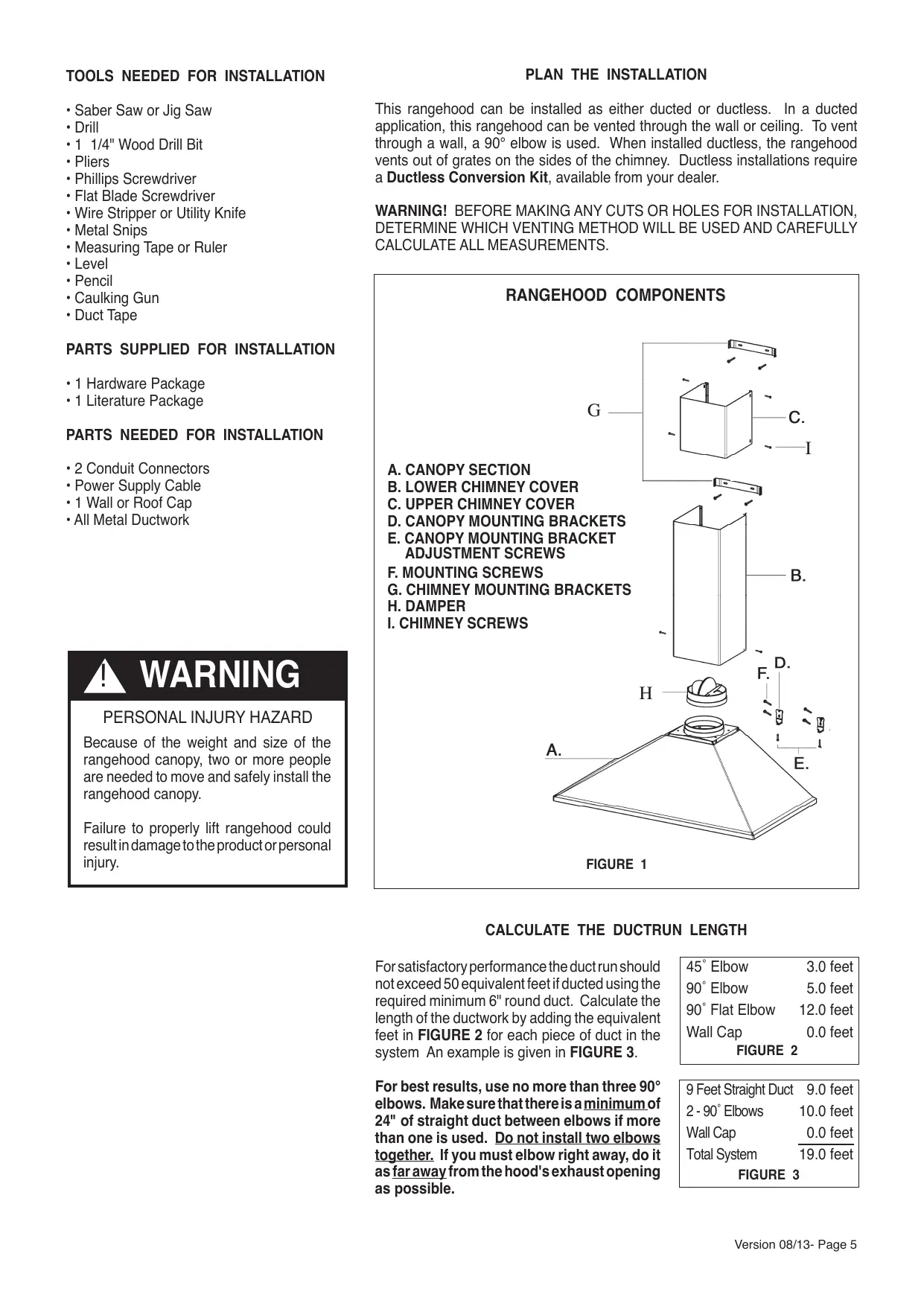
Because of the weight and size of the rangehood canopy, two or more people are needed to move and safely install the rangehood canopy.
Failure to properly lift rangehood could result in damage to the product or personal injury.
PLAN THE INSTALLATION
This rangehood can be installed as either ducted or ductless. In a ducted application, this rangehood can be vented through the wall or ceiling. To vent through a wall, a 90° elbow is used. When installed ductless, the rangehood vents out of grates on the sides of the chimney. Ductless installations require a Ductless Conversion Kit, available from your dealer.
WARNING! BEFORE MAKING ANY CUTS OR HOLES FOR INSTALLATION, DETERMINE WHICH VENTING METHOD WILL BE USED AND CAREFULLY CALCULATE ALL MEASUREMENTS.
RANGEHOOD COMPONENTS

text_image
A. CANOPY SECTION B. LOWER CHIMNEY COVER C. UPPER CHIMNEY COVER D. CANOPY MOUNTING BRACKETS E. CANOPY MOUNTING BRACKET ADJUSTMENT SCREWS F. MOUNTING SCREWS G. CHIMNEY MOUNTING BRACKETS H. DAMPER I. CHIMNEY SCREWSFIGURE 1
CALCULATE THE DUCTRUN LENGTH
For satisfactory performance the duct run should not exceed 50 equivalent feet if ducted using the required minimum 6" round duct. Calculate the length of the ductwork by adding the equivalent feet in FIGURE 2 for each piece of duct in the system. An example is given in FIGURE 3.
For best results, use no more than three 90° elbows. Make sure that there is a minimum of 24" of straight duct between elbows if more than one is used. Do not install two elbows together. If you must elbow right away, do it as far away from the hood's exhaust opening as possible.
| 45° Elbow | 3.0 feet |
| 90° Elbow | 5.0 feet |
| 90° Flat Elbow | 12.0 feet |
| Wall Cap | 0.0 feet |
FIGURE 2
| 9 Feet Straight Duct | 9.0 feet |
| 2 - 90° Elbows | 10.0 feet |
| Wall Cap | 0.0 feet |
| Total System | 19.0 feet |
FIGURE 3
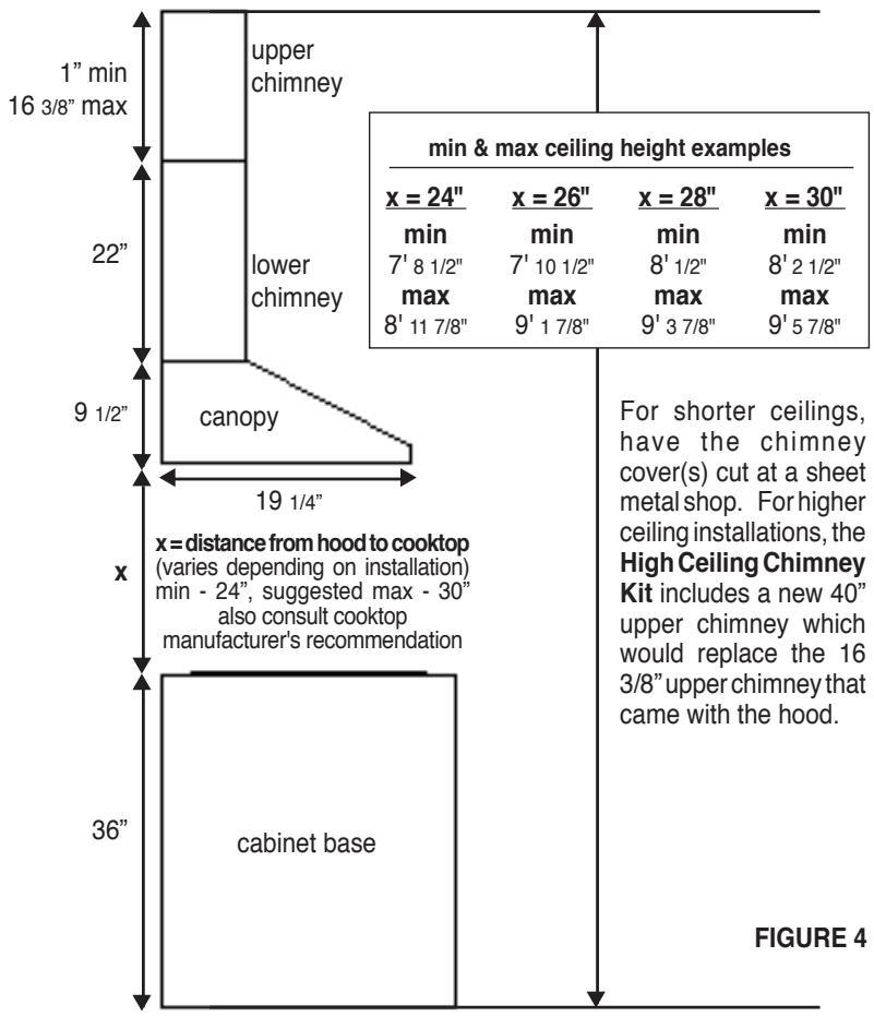
INSTALLATION DIMENSIONS
The Synthesis chimneys are adjustable and designed to meet varying ceiling heights as indicated in FIGURE 4. The chimneys can be adjusted for ceilings between 7' 8 1/2" and 9' 5 7/8" depending on the distance between the bottom of the hood and the cooktop (distance x in FIGURE 4).
other
| x (min) | x (max) | | ------- | ------- | | 24" | 26" | | 7' | 10 | | 8' | 1/2" | | 11" | 7/8" | | 22" | 16/3/8" | | 9 | 1/2" | | 19 | 1/4" | | 36" | 36" |
text_image
Y = 3 3/4" 4 3/4" 3/4" 8 1/4" 32 1/4" min. 24" min. FIGURE 5PREPARE THE WALL
- Disconnect and move freestanding range from cabinet opening to provide easier access to upper cabinet and rear wall. Put a thick, protective covering over cooktop, set-in range or countertop to protect from damage or dirt.
- Determine and clearly mark with a pencil the center line on the wall where the rangehood will be installed.
- The canopy attaches to the wall by two mounting brackets (1 in FIGURE 5). The canopy of the rangehood hangs on the two brackets which must be mounted with the flanges on the top of the bracket and pointing away from the wall. Before installing the brackets, the adjustment screws must be installed into the bottom of the bracket. These two screws are provided in the hardware package and have hexagon heads with a slot for a flat blade screwdriver. The dimensions illustrate mounting the canopy 24" above the cooking surface.
- The chimney mounts by two brackets (2 in FIGURE 5). Note the position of the brackets. The top bracket should be installed about 1/8" away from the ceiling. The bottom bracket must be installed at the bottom point of the upper chimney sleeve.
Determine the proper location for each bracket and install the brackets on the wall. MAKE SURE THAT THE BRACKETS ARE SECURELY FASTENED TO THE WALL.
- Determine and make all necessary cuts in the wall for the ductwork. Install the ductwork before the rangehood.
- Determine the proper location for the Power Supply Cable (FIGURE 6). Use a 1 1/4" Drill Bit to make this hole. Run the Power Supply Cable. Use caulking to seal around the hole. DO NOT turn on the power until installation is complete.
NOTE: The wiring box may be located on the right or left side in the hood. Use the mirror image of FIGURE 6 if located on the opposite side. An alternate method of bringing power to hood is feeding the cable thru the strain relief located next to the duct hole on top of the hood (on the centerline, 10" up from the bottom of the hood.)

text_image
30 MODELS 3 5/8" 1 1/4" 7 1/4" 30" 24" min 36 MODELS FIGURE 6INSTALL THE RANGEHOOD
- Remove the unit from the carton and place on a flat surface for assembly. Cover the surface to prevent accidental damage. Remove all parts including the mounting hardware before discarding the carton.
- Remove the grease filters from the unit and set aside. The grease filters are removed by pressing the handle in front of the filter (FIGURE 7). When replacing, make sure that the filters are properly positioned with the handles in front and visible.

text_image
FIGURE 7- Remove the cover from the field wiring compartment. Remove the wiring electrical knockout using a flat-blade screwdriver. Feed the Power Supply Cable through the electrical knockout.
- Hang the canopy on the brackets (1 in FIGURE 8). There are two rectangular holes on the rear of the canopy. The brackets pass through these holes and the canopy hangs from the flanges on the brackets. Due to the weight of the canopy, two people should lift it to avoid injuries. Make sure that the canopy is secure on the brackets before releasing.
- Level the canopy. The height and level of the canopy can be adjusted by rotating the adjustment screws (W in FIGURE 8) on each side of the blower inside the rangehood.

text_image
FIGURE 8 W 1- Connect the Power Supply Cable to the rangehood. Attach the White lead of the power supply to the White lead of the rangehood with a twist-on type wire connector. Attach the Black lead of the power supply to the Black lead of the rangehood with a twist-on type wire connector. Connect the Green (Green and Yellow) ground wire under the Green grounding screw.
- Replace the field wiring compartment cover and the grease filters.
- For ducted installations, the damper must be attached to the exhaust opening on the top of the canopy. Connect the ductwork and seal all connections with duct tape.
FOR DUCTLESS INSTALLATIONS
Do not use the DAMPER (I In FIGURE 1) for ductless installations. The UPPER CHIMNEY COVER must be installed first, before the LOWER CHIMNEY DUCTLESS.
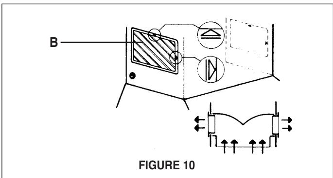
Ductless installations require a Ductless Conversion Kit. This kit consists of a LOWER CHIMNEY DUCTLESS (A in FIGURE 9) with holes for the exhaust air, a DUCTLESS DIVERTER (C), two VENT GRIDS (B) to cover the holes in the chimney cover, and two CHARCOAL FILTERS (D). The DUCTLESS DIVERTER must be installed before the LOWER CHIMNEY DUCTLESS is attached (as indicated by the arrow in FIGURE 9). The LOWER CHIMNEY COVER without holes (B in FIGURE 1) should be discarded.

text_image
A B C D FIGURE 9Once the LOWER CHIMNEY DUCTLESS with holes is installed, the VENT GRIDS (B) are inserted into the holes (FIGURE 10).
text_image
B FIGURE 10Attach the CHARCOAL FILTERS to both sides of the blower (as indicated in FIGURE 11). Install the grease filters.

text_image
FIGURE 11- The chimney must be attached to the body of the rangehood, as indicated in FIGURE 12. The UPPER CHIMNEY COVER (C) must be installed first, then the LOWER CHIMNEY COVER (B) wraps around it. Both sections are secured to the wall under the CHIMNEY MOUNTING BRACKETS (H). Secure the UPPER CHIMNEY COVER to the MOUNTING BRACKETS with the CHIMNEY SCREWS (J). Secure the LOWER CHIMNEY COVER to the CANOPY SECTION (A) with the CHIMNEY SCREWS (J).
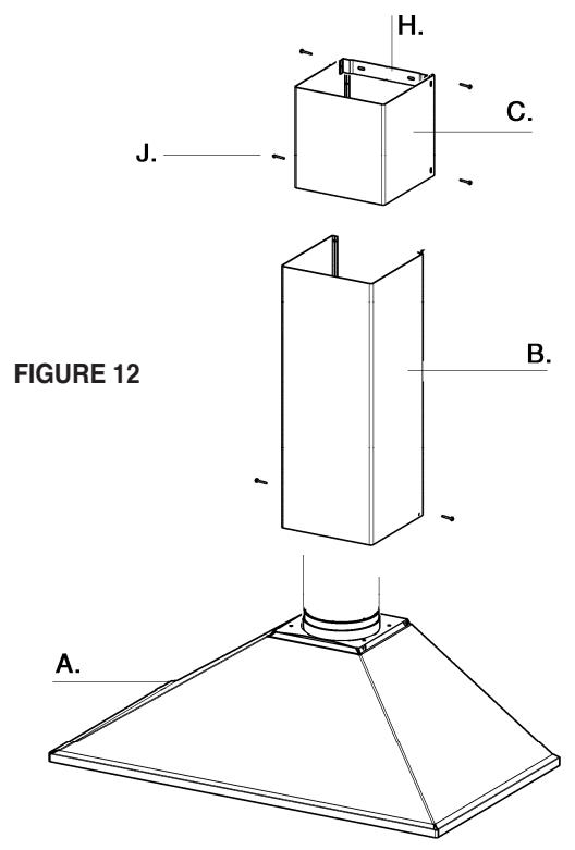
text_image
H. J. C. B. A. FIGURE 12- Turn the power supply on. Turn on blower and light. If the rangehood does not operate, check that the circuit breaker is not tripped or the house fuse blown. If the unit still does not operate, disconnect the power supply and check that the wiring connections have been made properly.
USE AND CARE INFORMATION
This rangehood system is designed to remove smoke, cooking vapors and odors from the cooktop area.
For Best Results
Start the rangehood several minutes before cooking to develop proper airflow. Allow the unit to operate for several minutes after cooking is complete to clear all smoke and odors from the kitchen.
Cleaning
The metal grease filters should be cleaned frequently in hot detergent solution or washed in the dishwasher. Stainless steel cleaner should be used on stainless rangehoods. Abrasives and scouring agents can scratch stainless steel finishes and should not be used to clean finished surfaces.
Replacing the Lamps
Purchase halogen bulb - (Max 20W, 12V, type MR11 bulb with glass lens)
Before attempting to replace the lamps, make sure that the light switch is turned off, USE CAUTION AS THE BULB MAY BE HOT. Remove the 2 screws (as indicated in FIGURE 14) that hold the light support and gently pull the support down from the hood. Remove the lamp from the light support and replace with new lamp. Replace the light support and fix it into place with the 2 screws.
An alternative method to replace the lamps is to use a 1 1/4" suction cup (FIGURE 15). Attach the suction cup to the bulb and pull firmly down on the bulb and replace with a new lamp.

natural_image
Illustration of a hand holding a mechanical device with wires and components (no text or symbols)FIGURE 13

natural_image
Simple line drawing of a glass plate with a small spherical object attached to it, no text or symbols present.FIGURE 14

text_image
M | | 1 V | | 3/i L | |FIGURE 15 - 3-SPEED / 3 VITESSE
Rangehood Control Panel
The control panel is located under the front of the canopy. The position and function of each control button are noted below (FIGURE 15).
Light On/Off Button ( L )
On/Off switch for the halogen lights. Press the light button to turn the light ON. and again to turn off.
Blower Off Button (M)
Off switch for the blower. The blower can be operated by pressing any of the speed buttons
Blower Speed Button ( V )
Speed control for blower. Press the switch "1" for LOW speed, "2" for MEDIUM speed and "3" for HIGH speed. Hold down the speed 3 button for 5 seconds to activate the intensive speed. Which operates the hood for 10 minutes on the high speed and then returns the previous speed.
NOTE: It is not recommended to use the lighting as a night light or for an extended time beyond normal cooking times. The halogen lights life span will be reduced.
All Faber products are warranted against any defect in materials or workmanship for the original purchaser for a period of 1 year from the date of original purchase. This warranty covers labor and replacement parts. To obtain warranty service, contact the dealer from whom you purchased the rangehood, or the local Faber distributor. If you cannot identify a local Faber distributor, contact us at (508) 358-5353 for the name of a distributor in your area.
The Following is not covered by Faber's warranty:
- Service calls to correct the installation of your range hood, to instruct you how to use your range hood, to replace or repair house fuses or to correct house wiring or plumbing.
- Service calls to repair or replace range hood light bulbs, fuses or filters. Those consumable parts are excluded from warranty coverage.
- Repairs when your range hood is used for other than normal, single-family household use.
- Damage resulting from accident, alteration, misuse, abuse, fire, flood, acts of God, improper installation, installation not in accordance with electrical or plumbing codes, or use of products not approved by Faber.
- Replacement parts or repair labor costs for units operated outside the United States or Canada, including any non-UL or C-UL approved Faber rangehoods.
- Repairs to the hood resulting from unauthorized modifications made to the rangehood.
- Expenses for travel and transportation for product service in remote locations and pickup and delivery charges. Faber range hoods should be serviced in the home.
Record Your Information Below:
Serial #: ____
Date of Purchase: ____
DIMENSIONS D'INSTALLATION
natural_image
Diagram of a window with a black arrow indicating direction, labeled 'FIGURE 7' (no text or symbols on the diagram itself)text_image
FIGURE 8 W 1INSTALLATIONS SANS CONDUIT
text_image
FIGURE 11text_image
H. J. C. B. A. FIGURE 12natural_image
Illustration of a hand holding a small mechanical device with a pointed tip, labeled 'FIGURE 13' (no text or symbols on the diagram itself)