
MAXIMA - Range hood FABER - Free user manual and instructions
Find the device manual for free MAXIMA FABER in PDF.
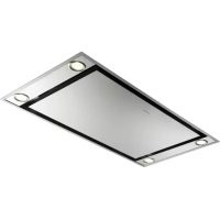
| Product type | Cooker hood |
| Brand | FABER |
| Model | MAXIMA |
| Safety distance from cooking surface | 650 mm (minimum) |
| Air outlet diameter | 150 mm (reducible to 120 mm) |
| Evacuation mode | Extractor or recirculation |
| Grease filters | Self-supporting metal, dishwasher safe (every 2 months) |
| Active carbon filter | Synthetic, non-washable, replace every 4 months (or more often depending on use) |
| Lighting | Halogen lamp 20 W |
| Number of speeds | 3 (minimum, medium, maximum) |
| Power supply | Mains, with bipolar switch (contact opening ≥3 mm) |
| Electrical class | I (mandatory earthing) |
| Use | Domestic |
| Maintenance | Clean with damp cloth and mild detergent |
| Drilling dimensions (bracket) | Ø 4.5 mm for screws, Ø 150 mm for evacuation |
| Weight | Not specified (estimated ~10-15 kg) |
| Spare parts | Filters, lamps, air outlet grille, closing profile, fixing screws |
| Repairability | Filters and lamp replaceable by user; power cord by approved after-sales service |
Frequently Asked Questions - MAXIMA FABER
User questions about MAXIMA FABER
0 question about this device. Answer the ones you know or ask your own.
Ask a new question about this device
Download the instructions for your Range hood in PDF format for free! Find your manual MAXIMA - FABER and take your electronic device back in hand. On this page are published all the documents necessary for the use of your device. MAXIMA by FABER.
USER MANUAL MAXIMA FABER
natural_image
Technical line drawing of a mechanical housing or enclosure component (no text or symbols)Libretto di Istruzioni Instructions Manual Manuel d'Instructions Bedienungsanleitung Gebruiksaanwijzing Instrukcja Obsługi
INDICE
IT
CONSIGLI E SUGGERIMENTI.... 3
CARATTERISTICHE....6
INSTALLAZIONE 7
USO 9
MANUTENZIONE 10
INDEX
EN
RECOMMENDATIONS AND SUGGESTIONS 13
CHARACTERISTICS 16
INSTALLATION....17
USE 19
MAINTENANCE 20
SOMMAIRE
FR
CONSEILS ET SUGGESTIONS....23
CARACTERISTIQUES....26
INSTALLATION 27
UTILISATION 29
ENTRETIEN 30
INHALTSVERZEICHNIS
DE
natural_image
Illustration of a chemical experiment setup with a conical flask, test tube, and control panel (no text or symbols)
natural_image
Diagram of a pipe connection with a 2° angle indicator, showing structural components without any text or symbols.natural_image
Illustration of a cooking setup with a pot and stove, featuring a crossed green pan and smoke (no text or symbols)natural_image
Technical line drawing of a mechanical assembly with green components and a central circular component (no text or symbols)MONTAGGIO CON FISSAGGIO A SCATTO
natural_image
Diagram of a device with green arrows indicating motion or movement, no text or symbols presentConnessioni
USCITA ARIA VERSIONE ASPIRANTE
PULIZIA FILTRI ANTIGRASSO METALLICI MULTISTRATO
natural_image
Illustration showing a hand interacting with a green mesh panel and two views of a mechanical device (no text or symbols present)natural_image
Illustration showing a hand interacting with a green electronic device panel, alongside two views of a device with internal components (no text or symbols present)natural_image
Diagram of a mechanical device with rotating components and green arrows indicating motion (no text or symbols)
natural_image
Diagram of a mechanical device with rotating components and green arrows indicating motion (no text or symbols)natural_image
Line drawing of a hand holding a small object with a green circular top (no text or symbols)| Lampada | Assorbimento (W) | Attacco | Voltaggio (V) | Dimensione (mm) | Codice ILCOS |
| 28 | E14 | 220 – 240 | 104 x 35 | HSGSB/C/UB-28-220/240-E14 | |
| 28 | E14 | 230 | 85x25 | HDG-28-230-E14-25 | |
| 20 | G4 | 12 | 33 x 9 | HSG/C/UB-20-12-G4 | |
| [WAG4] | 35 | GU10 | 230 | 51 x 50,7 | HAGS-35-230-GU10-51/40 |
| 50 | GU10 | 230 | 51 x 50,7 | HAGS-35-230-GU10-51/20 | |
 | 20 | GU4 | 12 | 40 x 35 | HRGS-20-12-GU4-35/30 |
| 20 | GU5.3 | 12 | 46 x 51 | HRGS-20-12-GU5.3-50/10 | |
| 16 | G13 | 95 | 720 x 26 | FD-16/40/1B-E-G13-26/720 | |
| 18 | G13 | 57 | 589,8 x 26 | FD-18/40/1B-E-G13-26/600 | |
| 9 | G23 | 60 (lampada)220-240 (starter) | 167 x 28 | FSD-9/27/1B-I-G23 | |
| 11 | G23 | 91 (lampada)220-240 (starter) | 235,8 x 28 | FSD-11/40/1B-I-G23 |
The Instructions for Use apply to several versions of this appliance. Accordingly, you may find descriptions of individual features that do not apply to your specific appliance.
INSTALLATION
- The manufacturer will not be held liable for any damages resulting from incorrect or improper installation.
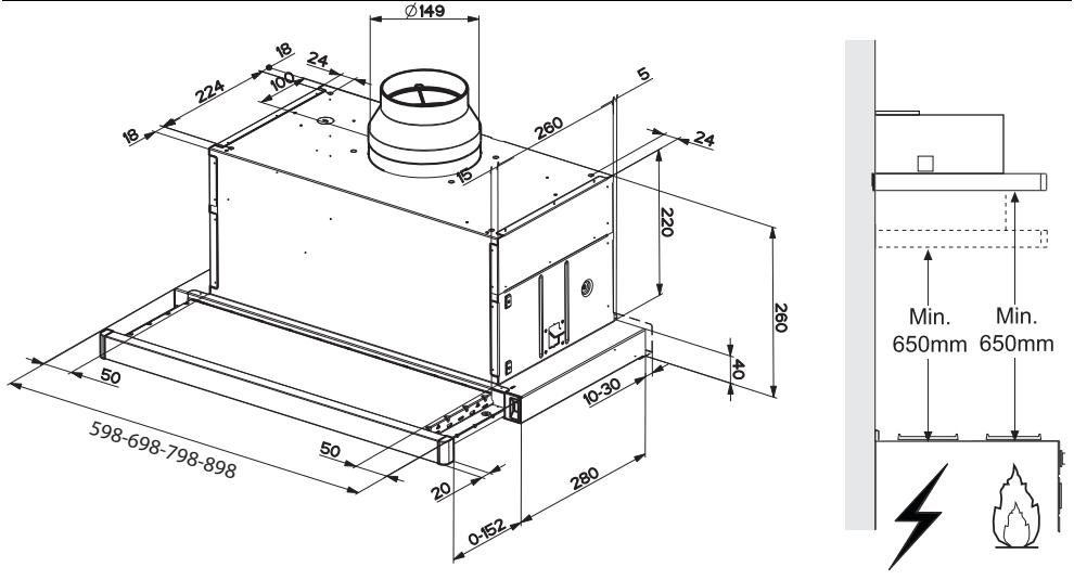
- The minimum safety distance between the cooker top and the extractor hood is 650 mm (some models can be installed at a lower height, please refer to the paragraphs on working dimensions and installation).
- Check that the mains voltage corresponds to that indicated on the rating plate fixed to the inside of the hood.
- For Class I appliances, check that the domestic power supply guarantees adequate earthing.
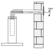
Connect the extractor to the exhaust flue through a pipe of minimum diameter 120 mm. The route of the flue must be as short as possible.
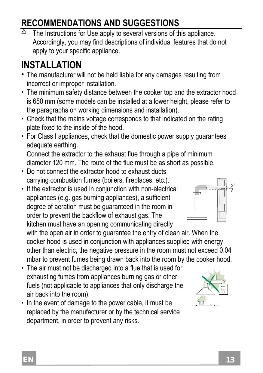
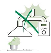
- Do not connect the extractor hood to exhaust ducts carrying combustion fumes (boilers, fireplaces, etc.).
- If the extractor is used in conjunction with non-electrical appliances (e.g. gas burning appliances), a sufficient degree of aeration must be guaranteed in the room in order to prevent the backflow of exhaust gas. The kitchen must have an opening communicating directly
with the open air in order to guarantee the entry of clean air. When the cooker hood is used in conjunction with appliances supplied with energy other than electric, the negative pressure in the room must not exceed 0,04 mbar to prevent fumes being drawn back into the room by the cooker hood.
- The air must not be discharged into a flue that is used for exhausting fumes from appliances burning gas or other fuels (not applicable to appliances that only discharge the air back into the room).
- In the event of damage to the power cable, it must be replaced by the manufacturer or by the technical service department, in order to prevent any risks.
natural_image
Illustration of a chemical experiment setup with a conical flask, thermometer, and smokestack (no text or symbols)- If the instructions for installation for the gas hob specify a greater distance specified above, this has to be taken into account. Regulations concerning the discharge of air have to be fulfilled.
- Use only screws and small parts in support of the hood.
Warning: Failure to install the screws or fixing device in accordance with these instructions may result in electrical hazards.
- Connect the hood to the mains through a two-pole switch having a contact gap of at least 3 mm.
USE
- The extractor hood has been designed exclusively for domestic use to eliminate kitchen smells.
- Never use the hood for purposes other than for which it has been designed.
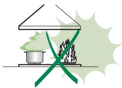
- Never leave high naked flames under the hood when it is in operation.
- Adjust the flame intensity to direct it onto the bottom of the pan only, making sure that it does not engulf the sides.
- Deep fat fryers must be continuously monitored during use: overheated oil can burst into flames.
- Do not flambè under the range hood; risk of fire.
- This appliance can be used by children aged from 8 years and above and persons with reduced physical, sensory or mental capabilities or lack of
natural_image
Illustration of a cooking setup with a pot and stove, featuring a crossed green pan and smoke (no text or symbols)experience and knowledge if they have been given supervision or instruction concerning use of the appliance in a safe way and understand the hazards involved. Children shall not play with the appliance. Cleaning and user maintenance shall not be made by children without supervision.
- This appliance is not intended for use by persons (including children) with reduced physical, sensory or mental capabilities, or lack of experience and knowledge, unless they have been given supervision or instruction concerning use of the appliance by a person responsible for their safety.
- “CAUTION: Accessible parts may become hot when used with cooking appliances.”
MAINTENANCE
- Switch off or unplug the appliance from the mains supply before carrying out any maintenance work.
- Clean and/or replace the Filters after the specified time period (Fire hazard).
- The Grease filters must be cleaned every 2 months of operation, or more frequently for particularly heavy usage, and can be washed in a dishwasher.
- The Activated charcoal filter is not washable and cannot be regenerated, and must be replaced approximately every 4 months of operation, or more frequently for particularly heavy usage.
- "Failure to carry out cleaning as indicated will result in a fire hazard".
- Clean the hood using a damp cloth and a neutral liquid detergent.
The symbol ☒ on the product or on its packaging indicates that this product may not be treated as household waste. Instead it shall be handed over to the applicable collection point for the recycling of electrical and electronic equipment. By ensuring this product is disposed of correctly, you will help prevent potential negative consequences for the environment and human health, which could otherwise be caused by inappropriate waste handling of this product. For more detailed information about recycling of this product, please contact your local city office, your household waste disposal service or the shop where you purchased the product.
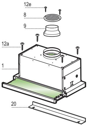
Components
| Ref. | Q.ty | Product Components |
| 1 | 1 | Hood Body, complete with: Controls, Light, Blower, Filters |
| 8 | 1 | Directional Air Outlet grille |
| 9 | 1 | Reducer Flange ø 150-120 mm |
| 20 | 1 | Closing element |
| Ref. | Q.ty | Installation Components |
| 12a | 4 | Screws 4,2 x 44,4 |
| 12e | 2 | Screws 2,9 x 9,5 |
| Q.ty | Documentation | |
| 1 | Instruction Manual | |
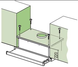
Drilling the Support surface and Fitting the Hood SCREW FITTING
- The hood support surface must be 220 mm above the bottom surface of the wall units.
- Drill the support with a 4,5 mm drill bit, using the drilling template provided.
- Cut a hole 150 mm in size on the support surface, using the drilling template provided.
• Fix using the 4 screws 12a (4,2 x 44,4) provided.
natural_image
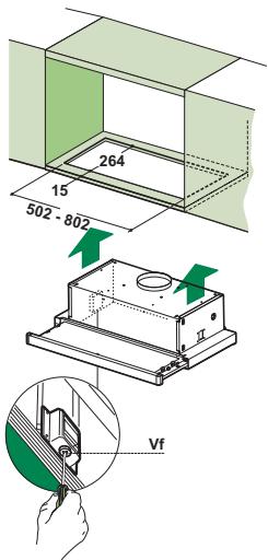
Technical line drawing of a mechanical assembly with green components and a central circular component (no text or symbols)SNAP-ON FITTING
- The hood can be installed either directly on the bottom surface of the wall units using snap-on side supports.
- Cut a fitted opening in the bottom surface of the wall unit, as shown.
- Insert the hood until the side supports snap into place.
- Lock in position by tightening the screws Vf from underneath the hood.
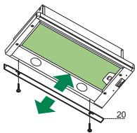
CLOSING ELEMENT
- The space between the edge of the hood and the rear wall can be closed by applying the element 20 provided, using the screws supplied for this purpose.
natural_image
Diagram of a device casing with green internal components and directional arrows indicating movement (no text or symbols)Connections
DUCTED VERSION AIR EXHAUST SYSTEM
When installing the ducted version, connect the hood to the chimney using either a flexible or rigid pipe 150 or 120 mm, the choice of which is left to the installer.
- To install a 120 mm air exhaust connection, insert the reducer flange 9 on the hood body outlet.
- Fix the pipe in position using sufficient pipe clamps (not supplied).
- Remove possible charcoal filters.
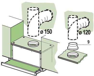
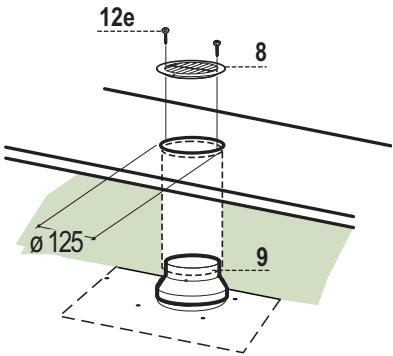
RECIRCULATION VERSION AIR OUTLET
- Cut a hole 125 mm in any shelf that may be positioned over the hood.
- Insert the reducer flange 9 on the hood body outlet.
- Connect the flange to the outlet on the shelf over the hood by using a flexible or rigid pipe 120mm .
- Fix the pipe in position using sufficient pipe clamps (not supplied).
- Fix the air outlet grid 8 on the recirculation air outlet by using the 2 screws 12e (2,9 x 9,5) provided.
- Ensure that the activated charcoal filters have been inserted.
ELECTRICAL CONNECTION
- Connect the hood to the mains through a two-pole switch having a contact gap of at least 3 mm.
- When opening the sliding carriage for the first time after installing the hood, pull it out briskly until it clicks.
Control panel
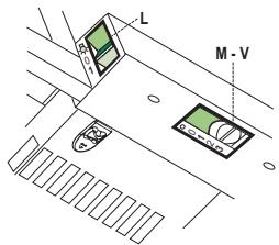

L Light Switches the lighting system on and off.
M Motor Switches the extractor motor on and off.
V Speed Sets the operating speed of the extractor:
-
Low speed, used for a continuous and silent air change in the presence of light cooking vapour.
-
Medium speed, suitable for most operating conditions given the optimum treated air flow/noise level ratio.
-
Maximum speed, used for eliminating the highest cooking vapour emission, including long periods.
L Light Switches the lighting system on and off.
M Motor Switches the extractor motor on and off.
V Speed Sets the operating speed of the extractor:
-
Low speed, used for a continuous and silent air change in the presence of light cooking vapour.
-
Medium speed, suitable for most operating conditions given the optimum treated air flow/noise level ratio.
Grease filters
CLEANING METAL SELF-SUPPORTING GREASE FILTERS
- The filters must be cleaned every two months of operation, or more frequently with heavy usage, and can be washed in a dishwasher.
- Remove the filters one at a time, after disconnecting the relative fastening elements.
- Wash the filters, taking care not to bend them. Allow them to dry before refitting.
- When refitting the filters, make sure that the handle is visible on the outside.
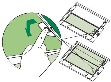
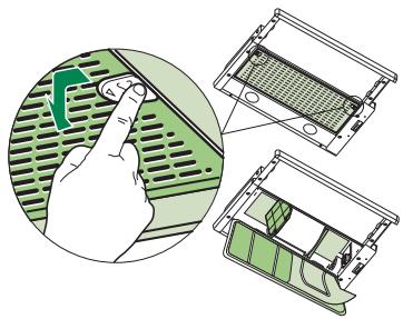
CLEANING MULTILAYER METAL GREASE FILTERS
- The filters must be cleaned every two months of operation, or more frequently with heavy usage, and can be washed in a dishwasher.
- Release the filter retaining grill using the lateral sliding handles.
- Remove the filter retaining clips.
- Remove and wash the filters. Allow them to dry before refitting.
- Replace the filters on the grill, fix them in position using the filter retaining clips and close the filter retaining grill.
natural_image
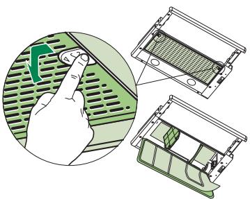
Illustration showing a hand inserting a component into a green circuit board, with two views of the device inside (no text or symbols present)REPLACING SYNTHETIC GREASE FILTER
- The filter is not washable and cannot be regenerated, and must be replaced approximately every two months of use, or more frequently with heavy usage.
- Release the filter holder frame using the lateral sliding handles.
- Remove the filter retaining clips.
- Replace the saturated synthetic filter.
- Fix the new synthetic filter using the retaining clips and close the filter holder frame.
natural_image
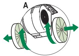
Illustration showing a hand interacting with a green mesh panel and three views of a mechanical device (no text or symbols present)These filters are not washable and cannot be regenerated, and must be replaced approximately every 4 months of operation, or more frequently with heavy usage.
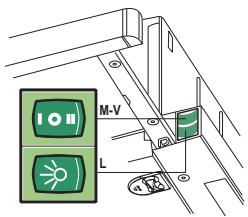
REPLACING THE ACTIVATED CHARCOAL FILTER
- Remove the metal grease filters
- Remove the saturated activated charcoal filter as shown (A).
• Fit the new filters (B). - Replace the metal grease filters.
natural_image
Diagram of a mechanical device with rotating wheels and green arrows indicating motion (no text or symbols)
natural_image
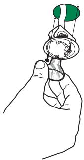
Diagram of a mechanical or fluidic device with green arrows indicating flow or movement, no text or symbols present.LIGHT REPLACEMENT
20 W halogen light.
- Remove the 2 screws fixing the Lighting support, and pull it out of from the Hood.
- Extract the lamp from the Support.
- Replace with another of the same type, making sure that the two pins are properly inserted in the lamp holder socket holes.
- Refit the Support, fixing it in place with the two screws removed as above.
natural_image
Line drawing of a hand holding a small object with a green circular top (no text or symbols)| Lamp | Power (W) | Socket | Voltage (V) | Dimension (mm) | ILCOS Code |
| 28 | E14 | 220 – 240 | 104 x 35 | HSGSB/C/UB-28-220/240-E14 | |
| 28 | E14 | 230 | 85x25 | HDG-28-230-E14-25 | |
| 20 | G4 | 12 | 33 x 9 | HSG/C/UB-20-12-G4 | |
 | 35 | GU10 | 230 | 51 x 50,7 | HAGS-35-230-GU10-51/40 |
| 50 | GU10 | 230 | 51 x 50,7 | HAGS-35-230-GU10-51/20 | |
 | 20 | GU4 | 12 | 40 x 35 | HRGS-20-12-GU4-35/30 |
| 20 | GU5.3 | 12 | 46 x 51 | HRGS-20-12-GU5.3-50/10 | |
| 16 | G13 | 95 | 720 x 26 | FD-16/40/1B-E-G13-26/720 | |
| 18 | G13 | 57 | 589,8 x 26 | FD-18/40/1B-E-G13-26/600 | |
| 9 | G23 | 60 (lamp)220-240 (starter) | 167 x 28 | FSD-9/27/1B-I-G23 | |
| 11 | G23 | 91 (lamp)220-240 (starter) | 235,8 x 28 | FSD-11/40/1B-I-G23 |
natural_image
Illustration of a chemical experiment setup with a conical flask, thermometer, and smoke rising (no text or symbols)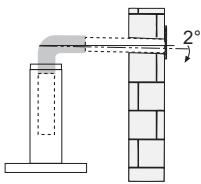
natural_image
Illustration of a greenhouse with a stove and fire extinguisher crossed out by a green ribbon (no text or symbols)natural_image
Technical line drawing of a mechanical assembly with a central circular component and two vertical supports (no text or symbols)MONTAGE AVEC FIXATION PAR ENCLIQUETAGE
natural_image
Diagram of a device with green internal components and arrows indicating motion or movement, no text or symbols present.Branchements
SORTIE AIR VERSION ASPIRANTE
NETTOYAGE FILTRES ANTI-GRAISSE METALLIQUES MULTICOUCHE
natural_image
Illustration showing a hand interacting with a green electronic device panel, alongside two views of the internal grid (no text or symbols present)REEMPLACEMENT FILTRE ANTI-GRAISSE SYNTHÉTIQUE
natural_image
Illustration showing a hand pressing a button on a green grid device, with three views of the device's internal structure (no text or symbols present)REPLACEMENT FILTRE AU CHARBON ACTIF
natural_image
Diagram of a mechanical device with rotating components and green arrows indicating motion (no text or symbols)
natural_image
Diagram of a mechanical or fluidic device with green arrows indicating flow or movement, no text or symbols present.REPLACEMENT LAMPES
natural_image
Line drawing of a hand holding a small object with a green sphere above it (no text or symbols)| Ampoule | Absorption (W) | Culot | Voltage (V) | Dimensions (mm) | Code ILCOS |
| 28 | E14 | 220 – 240 | 104 x 35 | HSGSB/C/UB-28-220/240-E14 | |
| 28 | E14 | 230 | 85x25 | HDG-28-230-E14-25 | |
| 20 | G4 | 12 | 33 x 9 | HSG/C/UB-20-12-G4 | |
 | 35 | GU10 | 230 | 51 x 50,7 | HAGS-35-230-GU10-51/40 |
| 50 | GU10 | 230 | 51 x 50,7 | HAGS-35-230-GU10-51/20 | |
| [BYX8] | 20 | GU4 | 12 | 40 x 35 | HRGS-20-12-GU4-35/30 |
| 20 | GU5.3 | 12 | 46 x 51 | HRGS-20-12-GU5.3-50/10 | |
| 16 | G13 | 95 | 720 x 26 | FD-16/40/1B-E-G13-26/720 | |
| 18 | G13 | 57 | 589,8 x 26 | FD-18/40/1B-E-G13-26/600 | |
| 9 | G23 | 60 (ampoule)220-240 (starter) | 167 x 28 | FSD-9/27/1B-I-G23 | |
| 11 | G23 | 91 (ampoule)220-240 (starter) | 235,8 x 28 | FSD-11/40/1B-I-G23 |

natural_image
Illustration of a chemical experiment setup with a conical flask, thermometer, and smokestack (no text or symbols)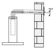
natural_image
Illustration of a cooking setup with a pot and stove, featuring a crossed green ribbon (no text or symbols)natural_image
Technical line drawing of a mechanical assembly with a central circular component and two vertical supports (no text or symbols)natural_image
3D diagram of a device casing with green internal panel and directional arrows indicating movement (no text or symbols)natural_image
Illustration showing a hand pressing down on a green ventilation grille next to two views of a device with mesh structure (no text or symbols)natural_image
Illustration showing a hand interacting with a green ventilation grille and three views of a mechanical device (no text or symbols present)natural_image
Line drawing of a hand holding a small object with a green sphere above it (no text or symbols)| Lampe | Leistung (W) | Fassung | Spannung (V) | Größe (mm) | ILCOS-Code |
| 124-03 | 28 | E14 | 220 – 240 | 104 x 35 | HSGSB/C/UB-28-220/240-E14 |
| 127-03 | 28 | E14 | 230 | 85x25 | HDG-28-230-E14-25 |
| 127-03 | 20 | G4 | 12 | 33 x 9 | HSG/C/UB-20-12-G4 |
| 128-03 | 35 | GU10 | 230 | 51 x 50,7 | HAGS-35-230-GU10-51/40 |
| 50 | GU10 | 230 | 51 x 50,7 | HAGS-35-230-GU10-51/20 | |
| 128-03 | 20 | GU4 | 12 | 40 x 35 | HRGS-20-12-GU4-35/30 |
| 20 | GU5.3 | 12 | 46 x 51 | HRGS-20-12-GU5.3-50/10 | |
| 129-03 | 16 | G13 | 95 | 720 x 26 | FD-16/40/1B-E-G13-26/720 |
| 18 | G13 | 57 | 589,8 x 26 | FD-18/40/1B-E-G13-26/600 | |
| 129-03 | 9 | G23 | 60 (Lampe)220-240 (Starter) | 167 x 28 | FSD-9/27/1B-I-G23 |
| 11 | G23 | 91 (Lampe)220-240 (Starter) | 235,8 x 28 | FSD-11/40/1B-I-G23 |

natural_image
Illustration of a chemical experiment setup with a conical flask, thermometer, and smokestack (no text or symbols)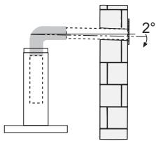
natural_image
Illustration of a cooking setup with a pot and fire, crossed by a green ribbon (no text or symbols)natural_image
Technical line drawing of a mechanical assembly with green components and a central circular component (no text or symbols)MONTAGE MET KLIKBEVESTIGING
natural_image
Diagram of a device casing with green internal panel and directional arrows indicating movement (no text or symbols)Aansluitingen
LUCHTUITLAAT AFZUIGVERSIE
REINIGING VAN DE UIT MEERDERE LAGEN BESTAANDE METALEN VETFILTERS
natural_image
Illustration showing a hand interacting with a green ventilation grille, alongside two views of a device casing (no text or symbols present)VERVANGING SYNTHETISCH VETFILTER
natural_image
Illustration showing a hand interacting with a green electronic device panel, alongside two views of the internal grid device (no text or symbols present)Geurfilter (filterversie)
natural_image
Diagram of a mechanical device with rotating wheels and green arrows indicating motion (no text or symbols)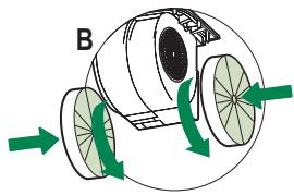
natural_image
Diagram of a mechanical or fluidic device with green arrows indicating flow or movement, no text or symbols present.VERVANGING VAN DE LAMPEN
natural_image
Line drawing of a hand holding a small object with a green sphere above it (no text or symbols)| Lamp | Stroomopname (W) | Aansluiting | Voltage (V) | Afmeting (mm) | ILCOS-code |
| [IMAGE] | 28 | E14 | 220 – 240 | 104 x 35 | HSGSB/C/UB-28-220/240-E14 |
| [IMAGE] | 28 | E14 | 230 | 85x25 | HDG-28-230-E14-25 |
| [IMAGE] | 20 | G4 | 12 | 33 x 9 | HSG/C/UB-20-12-G4 |
| 35 | GU10 | 230 | 51 x 50,7 | HAGS-35-230-GU10-51/40 |
| 50 | GU10 | 230 | 51 x 50,7 | HAGS-35-230-GU10-51/20 | |
| 20 | GU4 | 12 | 40 x 35 | HRGS-20-12-GU4-35/30 |
| 20 | GU5.3 | 12 | 46 x 51 | HRGS-20-12-GU5.3-50/10 | |
| [IMAGE] | 16 | G13 | 95 | 720 x 26 | FD-16/40/1B-E-G13-26/720 |
| 18 | G13 | 57 | 589,8 x 26 | FD-18/40/1B-E-G13-26/600 | |
| [IMAGE] | 9 | G23 | 60 (lamp)220-240 (starter) | 167 x 28 | FSD-9/27/1B-I-G23 |
| 11 | G23 | 91 (lamp)220-240 (starter) | 235,8 x 28 | FSD-11/40/1B-I-G23 |
natural_image
Illustration of a laboratory setup with a conical flask, test tube, and control panel emitting smoke (no text or symbols)natural_image
Diagram showing a pipe joint with a 2° angle and brick wall structure (no text or symbols)natural_image
Illustration of a cooking pot with steam rising, crossed by a green X (no text or symbols)natural_image
Technical diagram of a mechanical assembly with green walls and a central circular component, no text or symbols presentMONTAŻ Z ZACZEPAMI
natural_image
Diagram of a device with green arrows indicating motion or movement, no text or symbols presentPodłączenia
WYLOT POWIETRZA WERSJA Z WYCIĄGIEM
CZYSZCZENIE FILTRA METALLIC MULTI-LAYER
natural_image
Illustration showing a hand pressing down on a green ventilation grille next to three views of a mechanical device (no text or symbols present)SYNTETYCZNY SMAR WYMIANY FILTRA
natural_image
Illustration of a hand pressing a component on a green circuit board, with three views showing different mechanical components (no text or symbols present)natural_image
Diagram of a mechanical device with rotating wheels and green arrows indicating motion (no text or symbols)
natural_image
Diagram of a mechanical device with rotating components and green arrows indicating motion (no text or symbols)WYMIANA ŻARÓWEK
natural_image
Line drawing of a hand holding a small object with a green circular top (no text or symbols)| Typ żarówki | Moc (W) | Mocowanie | Napięcie (V) | Wymiary (mm) | Kod ILCOS |
| [###] | 28 | E14 | 220 – 240 | 104 x 35 | HSGSB/C/UB-28-220/240-E14 |
| [###] | 28 | E14 | 230 | 85x25 | HDG-28-230-E14-25 |
| [###] | 20 | G4 | 12 | 33 x 9 | HSG/C/UB-20-12-G4 |
| [HXYC] | 35 | GU10 | 230 | 51 x 50,7 | HAGS-35-230-GU10-51/40 |
| 50 | GU10 | 230 | 51 x 50,7 | HAGS-35-230-GU10-51/20 | |
| [2266] | 20 | GU4 | 12 | 40 x 35 | HRGS-20-12-GU4-35/30 |
| 20 | GU5.3 | 12 | 46 x 51 | HRGS-20-12-GU5.3-50/10 | |
| [###] | 16 | G13 | 95 | 720 x 26 | FD-16/40/1B-E-G13-26/720 |
| 18 | G13 | 57 | 589,8 x 26 | FD-18/40/1B-E-G13-26/600 | |
| ### | 9 | G23 | 60 (żarówka)220-240 (starter) | 167 x 28 | FSD-9/27/1B-I-G23 |
| 11 | G23 | 91 (żarówka)220-240 (starter) | 235,8 x 28 | FSD-11/40/1B-I-G23 |

- INDICE
- INDEX
- SOMMAIRE
- INHALTSVERZEICHNIS
- MONTAGGIO CON FISSAGGIO A SCATTO
- Connessioni
- USCITA ARIA VERSIONE ASPIRANTE
- PULIZIA FILTRI ANTIGRASSO METALLICI MULTISTRATO
- INSTALLATION
- USE
- MAINTENANCE
- Drilling the Support surface and Fitting the Hood SCREW FITTING
- SNAP-ON FITTING
- CLOSING ELEMENT
- Connections
- DUCTED VERSION AIR EXHAUST SYSTEM
- RECIRCULATION VERSION AIR OUTLET
- ELECTRICAL CONNECTION
- Control panel
- Grease filters
- CLEANING METAL SELF-SUPPORTING GREASE FILTERS
- CLEANING MULTILAYER METAL GREASE FILTERS
- REPLACING SYNTHETIC GREASE FILTER
- REPLACING THE ACTIVATED CHARCOAL FILTER
- LIGHT REPLACEMENT
- W halogen light.
- MONTAGE AVEC FIXATION PAR ENCLIQUETAGE
- Branchements
- SORTIE AIR VERSION ASPIRANTE
- NETTOYAGE FILTRES ANTI-GRAISSE METALLIQUES MULTICOUCHE
- REEMPLACEMENT FILTRE ANTI-GRAISSE SYNTHÉTIQUE
- REPLACEMENT FILTRE AU CHARBON ACTIF
- REPLACEMENT LAMPES
- MONTAGE MET KLIKBEVESTIGING
- Aansluitingen
- LUCHTUITLAAT AFZUIGVERSIE
- REINIGING VAN DE UIT MEERDERE LAGEN BESTAANDE METALEN VETFILTERS
- VERVANGING SYNTHETISCH VETFILTER
- Geurfilter (filterversie)
- VERVANGING VAN DE LAMPEN
- MONTAŻ Z ZACZEPAMI
- Podłączenia
- WYLOT POWIETRZA WERSJA Z WYCIĄGIEM
- CZYSZCZENIE FILTRA METALLIC MULTI-LAYER
- SYNTETYCZNY SMAR WYMIANY FILTRA
- WYMIANA ŻARÓWEK
Brand : FABER
Model : MAXIMA
Category : Range hood