
CUBIA ACTIVE - Water heater FABER - Free user manual and instructions
Find the device manual for free CUBIA ACTIVE FABER in PDF.
| Product Type | Electric storage water heater |
| Brand | FABER |
| Model | CUBIA ACTIVE |
| Capacity | 50 liters |
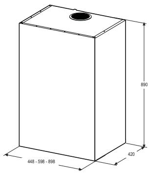
| Dimensions (H x W x D) | 600 x 400 x 400 mm |
| Weight | 20 kg |
| Power Supply | 230 V / 50 Hz |
| Power | 1500 W |
| Energy Class | C |
| Maximum Temperature | 65 °C |
| Thermostat Type | Adjustable |
| Freeze Protection | Yes |
| Safety | Overheat safety device |
| Tank Material | Enameled steel |
| Protection Anode | Magnesium |
| Connection | 1/2 inch |
| Maintenance | Annual draining recommended |
| Cleaning | Exterior with damp cloth |
| Warranty | 2 years |
Frequently Asked Questions - CUBIA ACTIVE FABER
User questions about CUBIA ACTIVE FABER
0 question about this device. Answer the ones you know or ask your own.
Ask a new question about this device
Download the instructions for your Water heater in PDF format for free! Find your manual CUBIA ACTIVE - FABER and take your electronic device back in hand. On this page are published all the documents necessary for the use of your device. CUBIA ACTIVE by FABER.
USER MANUAL CUBIA ACTIVE FABER
For your safety and correct operation of the appliance, read this manual carefully before installation and use. Always keep these instructions with the appliance even if you move or sell it. Users must fully know the operation and safety features of the appliance.

The wire connection has to be done by specialized technician.
- The manufacturer will not be held liable for any damages resulting from incorrect or improper installation.
- The minimum safety distance between the cooker top and the extractor hood is 650~mm (some models can be installed at a lower height, please refer to the paragraphs on working dimensions and installation).
- If the instructions for installation of the gas hob specify a greater distance, this must be respected.
- Check that the mains voltage corresponds to that indicated on the rating plate fixed to the inside of the hood.
- Means for disconnection must be incorporated in the fixed wiring in accordance with the wiring rules.
- For Class I appliances, check that the domestic power supply guarantees adequate earthing.
- Connect the extractor to the exhaust flue through a pipe of minimum diameter 120mm . The route of the flue must be as short as possible.
- Regulations concerning the discharge of air have to be fulfilled.
-
Do not connect the extractor hood to exhaust ducts carrying combustion fumes (boilers, fireplaces, etc.).
-
If the extractor is used in conjunction with non-electrical appliances (e.g. gas burning appliances), a sufficient degree of aeration must be guaranteed in the room in order to prevent the backflow of exhaust gas. When the cooker hood is used in conjunction with appliances supplied with energy other than electric, the negative pressure in the room must not exceed 0,04 mbar to prevent fumes being drawn back into the room by the cooker hood.
- The air must not be discharged into a flue that is used for exhausting fumes from appliances burning gas or other fuels.
- If the supply cord is damaged, it must be replaced from the manufacturer or its service agent.
- Connect the plug to a socket complying with current regulations, located in an accessible place.
- With regards to the technical and safety measures to be adopted for fume discharging it is important to closely follow the regulations provided by the local authorities.
WARNING: Before installing the Hood, remove the protective films.
- Use only screws and small parts supplied with the hood.
WARNING: Failure to install the screws or fixing device in accordance with these instructions may result in electrical hazards.
- Do not look directly at the light through optical devices (binoculars, magnifying glasses...).
- Do not flambé under the range hood; risk of fire.
- This appliance can be used by children aged from 8 years and above and persons with reduced physical, sensory or mental capabilities or lack of experience and knowledge if they have been given supervision or instruction concerning use of the appliance in a safe way and understand the hazards involved. Children shall not play with the appliance. Cleaning and user maintenance shall not be made by children without supervision.
- Children should be supervised to ensure that they do not play with the appliance.
- The appliance is not to be used by persons (including children) with reduced physical, sensory or mental capabilities, or lack of experience and knowledge, unless they have been given supervision or instruction.
Accessible parts may become hot when used with cooking appliances. - Clean and/or replace the Filters after the specified time period (Fire hazard). See paragraph Care and Cleaning.
- There shall be adequate ventilation of the room when the range hood is used at the same time as appliances burning gas or other fuels (not applicable to appliances that only discharge the air back into the room).
- The symbol on the product or on its packaging indicates that this product may not be treated as household waste. Instead it shall be handed over to the applicable collection point for the recycling of electrical and electronic equipment. By ensuring this product is disposed of correctly, you will help prevent potential negative consequences for the environment and human health, which could otherwise be caused by inappropriate waste handling of this product. For more detailed information about recycling of this product, please contact your local city office, your household waste disposal service or the shop where you purchased the product.
Dimensions
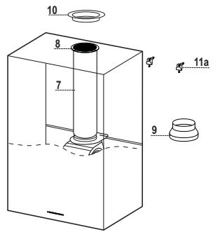
Components
| Ref. | Q.ty | Product components |
| 1 | 1 | Hood Body complete with: Controls, Light, Suction Unit, Filters, Lower Duct |
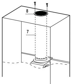
| 7 | 1 | PVC Pipe (fitted) |
| 8 | 1 | Inclinable grid (fitted) |
| 9 | 1 | Reduction flangeø 150-120 mm |
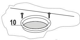
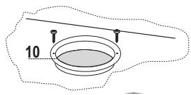
| 10 | 1 | Metal cover |
| Ref. | Q.ty | Assembly components |
| 11a | 2 | SB 12/10 Plugs |
| Q.ty | Documents | |
| 1 | Instruction Manual |
Boring the wall
If you want to use the hood in suction version with the air outlet at the back of the hood, make sure to follow the indications given below in the drawing for a correct boring operation of the air outlet opening.
| Type Hood | 45 | 60 | 90 |
| X | 180 | 240 | 390 |
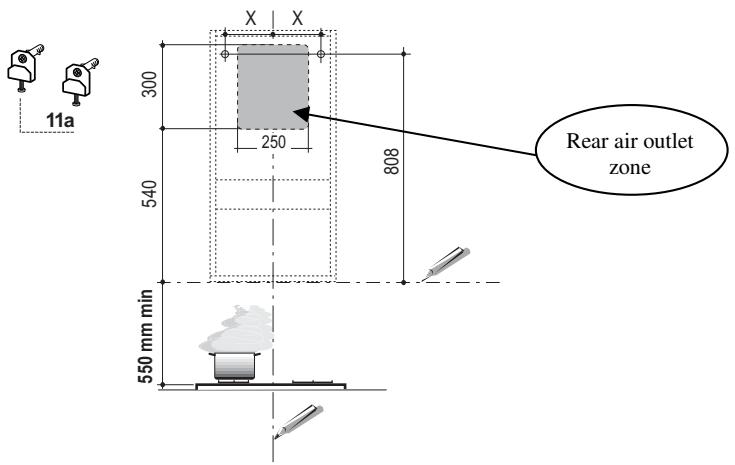
When installing the hood in recycling version it has to be taken into consideration that space remaining between the hood and the upper limit (ceiling or self) is at least 8-10 cm.
On the wall, trace:
- a vertical line up to the ceiling or top limit, at the centre of the area where you intend to fit the hood;
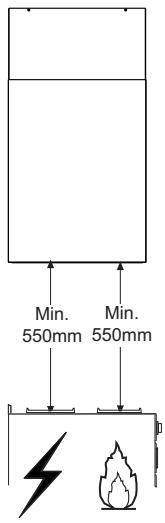
- a horizontal line at: 550mm min. above the cooking hob;
- As shown, mark a reference point at 808mm above the horizontal reference line, and at X mm (X= see table in figure) to the right of the vertical reference line.
- Repeat this operation on the opposite side, checking levelling.
- Drill the points marked using a 12mm bit
-
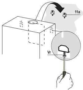
Insert plugs with screws and brackets 11a in the holes then tighten them.
-
Adjust the two screws Vr of brackets 11a, by just placing them in position.
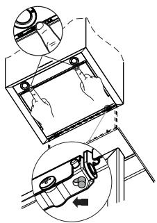
- Hook the hood body to the two brackets 11a.
- Pull the Comfort Panel to open it, remove the filters one by one, push them towards the rear part of the unit and pull downwards at the same time.
- From inside the hood body, tighten the screws Vr to level the body.
Connection
AIR OUTLET IN A DUCTING HOOD VERSION
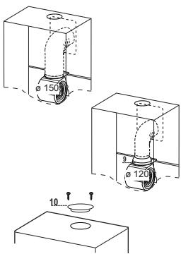
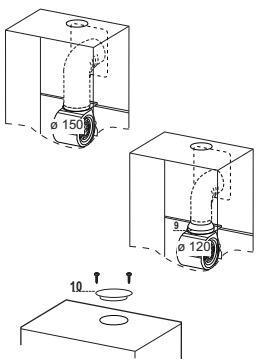
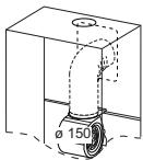
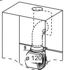
When installing the hood in ducting version, basing on the installer's choice, a rigid or a flexible pipe with a 150 or 120mm is used in order to connect the hood to the air outlet piping. The pipe connection can be made on the upper part or on the rear side of the hood.
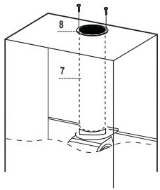
Before connecting the hood to the air outlet ducting remove the lateral air outlet grid 8 and the plastic tube 7. The adapting flange 9 has to be removed only in case the connecting diameter is 150.
REAR AIR OUTLET
- When drilling the air outlet hole in the wall proceed in accordance with the scheme in the part concerning the wall drilling.
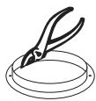
- Use a pair of tongs when breaking the rear air outlet hole in the wall.
- In case the connection is made by using a 120mm pipe insert the reduction flange 9 on the hood body outlet.
- Fix the pipe with an adequate quantity of pipe clamps. This material is not supplied together with the hood.
- Remove the charcoal filter if present.
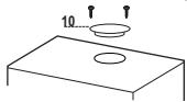
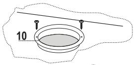
Fix the metal cover 10 to the upper air outlet hole of the hood by using the screws supplied.
UPPER AIR OUTLET
- In case the connection is made by using a 120mm pipe insert the reduction flange 9 on the hood body outlet.
- Use a pair of tongs when removing the central part of the metal cover 10. Fix the cover to the air outlet hole of the hood by using the screws supplied.
- Fix the pipe with an adequate quantity of pipe clamps. This material is not supplied together with the hood.
- Remove the charcoal filter if present.
AIR OUTLET IN A RECYCLING HOOD VERSION
- In case the components requested for the recycling functioning have been removed earlier these have to be positioned again.
- Put the plastic tube onto the flange 7.
- Place the air outlet grid 8 on the air outlet. Make sure that the position of the grid is correct.
- Make sure that charcoal filters have been placed inside the hood.

ELECTRICAL CONNECTION
- Connect the hood to the mains through a two-pole switch having a contact gap of at least 3mm .
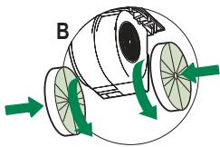
- Remove the grease filters (see paragraph Maintenance) being sure that the connector of the feeding cable is correctly inserted in the socket placed on the side of the fan.

Control panel
| Button | Function | Display |
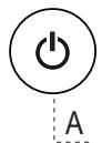
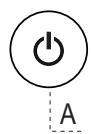
| A | Turns the suction motor on and off at speed one. | Displays the set speed |
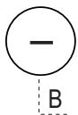
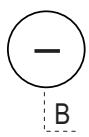
| B | Decreases the working speed. | Displays the set speed |
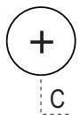
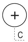
| C | Increases the working speed. | Displays the set speed |
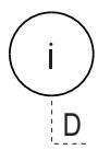
| D | Activate intensive speed from any other speed, including motor off. This speed is set to operate for 6 minutes, after which the system returns to the speed that was set before. Suitable to deal with maximum levels of cooking fumes. | Displays HI and the time remaining once very second. |
| Press and hold the button for approximately 5 seconds, with all the loads turned off (Motor and Lights), to turn the Activated Charcoal Filter alarm On and Off. | FC+Punto (2 flashes)-Alarm On. FC+Punto (1 flash)-Alarm Off. | |
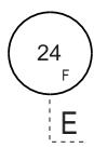
| E | 24H function Turns the suction motor on at speed one and effects one 10 minute extraction every hour. | Displays 24 and the spot at the bottom right flashes once every second, while the motor is running. It is disabled by pressing the button. |
| When the filters alarm is triggered, the alarm can be reset by pressing and holding this button for approximately 3 seconds. These indications are only visible when the motor is turned off. | FF flashes three times. When the procedure terminates, the indication shown previously turns off: FG indicates the need to wash the metal grease filters. The alarm is triggered after the Hood has been in operation for 100 working hours. FC indicates the need to change the activated charcoal filters, and also to wash the metal grease filters. The alarm is triggered after the Hood has been in operation for 200 working hours. | |
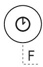
| F | Delay function Activate automatic switch-off with a 30' delay. Suitable to complete elimination of residual odours. Can be activated from any position, and is disabled by pressing the button or turning the motor off. | Displays the operating speed and the spot at the bottom right flashes once a second. |
| Press and hold the button for approximately 5 seconds, with all the loads turned off (Motor and Lights), to turn the Remote Control On and Off. | IR+Punto (2 flashes)-Alarm On. IR+Punto (1 flash)-Alarm Off. | |
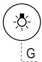
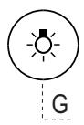
| G | Turns the lighting system on and off at maximum intensity. | |
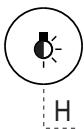
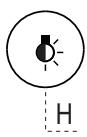
| H | Turns the Courtesy Lighting on and off. |
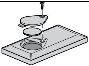
REMOTE CONTROL (OPTIONAL)
This appliance can be commanded using a remote control, powered by a CR2032 type 3 V battery (not supplied).
- Do not place the remote control near heat sources.
- Do not discard the batteries with normal waste, they must be put into the specific containers.
Cleaning the Comfort Panels
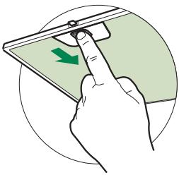
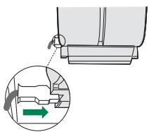
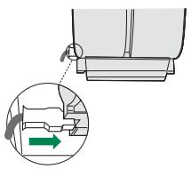
Pull the Comfort Panel to open it.
- Disconnect the panel from the hood canopy by sliding the fixing pin lever.
- The comfort panel must never be washed in a dishwasher.
- Clean the outside by using a damp cloth and neutral liquid detergent.
- Clean the inside as well by using a damp cloth and neutral detergent; do not use wet cloths or sponges, or jets of water; do not use abrasive substances.
- When the above operation has been completed, hook the panel back to the hood canopy and close it by turning the knob in the opposite direction.
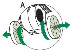
Metal grease filters
They can be washed in the dishwasher, and need to be cleaned whenever the FG sign appears on the display or at least once every 2 months use, or more frequently if use is particularly intensive.
Resetting the alarm signal
- Turn the Lights and the Suction motor off, then disable the 24h function, if enabled.
- Press button E (see the paragraph on Use).
Cleaning the Filters
- Open the Comfort panels by pulling on the recess.
- Remove the Filters one at a time, pushing them towards the back of the unit and at the same time pulling downward.
- Wash the Filters without bending them, and leave them to dry completely before replacing. (If the surface of the filter changes colour as time goes by, this will have absolutely no effect on the efficiency of the filter itself.)
- Replace, taking care to ensure that the handle faces forwards.
- Close the Comfort panels.
It cannot be washed or regenerated, and must be changed when the FC symbol on the display appears, or at least once every 4 months. The Alarm signal, if it has been activated, only appears when the Suction motor is turned on.
Activating the alarm signal
- In Recirculation Version Hoods, the Filter Saturation Alarm must be activated on installation or at a later date.
- Turn the Lights and the Suction Motor off.
-
Press D and hold for approximately 5 Seconds:
-
The message FC+Dot flashes twice, A.C. Filter saturation alarm ACTIVATED
- The message FC+Dot flashes once, A.C. Filter saturation alarm DEACTIVATED
CHANGING THE ACTIVATED CHARCOAL FILTER
Resetting the alarm signal
- Turn the Lights and the Suction motor off, then disable the 24h function, if enabled.
- Press button E (see the paragraph on Use).
Changing the Filter
- Open the Comfort panels by pulling on the recess.
- Remove the Metal grease filters.
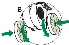
- Remove the saturated charcoal filter by releasing the fixing hooks.
- Fit the new filter and fasten it in its correct position.
- Replace the Metal grease filters.
- Close the Comfort panels.
Lighting unit
- For replacement contact technical support ("To purchase contact technical support").

AFSTANDSBEDIERING (OPTIE)
BbIITyCK BO3IYXA C3AIN
- UTo6bI cIeJIaTb OTBepCTHe IJIa OTBeIeHnBaO3Jyxa, cJIeIyET IIpNIEpKINBaTbCra CxEMbI, IIpNBcEHHoB B pa3IeJIe "OTBepCTHe B cTeHe".
KJIeIaMn OTKpbITb 3aIHee BbIpyckHoe OTBepCThe BO3Jyxa.
-Дя coeINHHeHnC trpy6KoI 120 MM BCTaBHTb IpeXOINHbI ΦJIaHeII 9 B bblIyckHoe OTBepcTne KOpIyca BbITJxKN.
3aKpeINITb Tpy6ky CIEIHaJIbHbIMN Tpy6HbIMN 3aJHMaMH. Heo6xoIHMbl MaTePnaJI He BXOJIHT B KOMIIJEKT IIOCTaBKN. - EcJH ecTb, BbIHyTb ΦHJIbTpbl IIpoTHB 3aIIaXOB Ha aKTHBOM yTJIe.
- YCTaHOBHTb 3aJIyIiKy 10 Ha BepXHEM BbIYcKHom OTBepCTHN BBITJAKKN IIpHJIaIaeMbIMN BnHTaMH.
BbIIYCK BO3IVXACBEPXV
-ДлcaоeINHHeHnCtpy6KoN0120MMBcTaBHTbIpeXOHNbI ΦJIaHeII9BbYbIyckHObOTBepcTHe KOpIyCa BbITJxKN.
KJIeIaMn BbHytB IeHTpaJIbHyIO aCht b3aJIyIiKN 10 H 3aKeIITb ee Ha BepXHEM BblYCKHOM OTBepCTHN BbITJxKKN IIpIIaIraEMbIMN BHTaMn.
3aKpeINITb Tpy6ky CIEIHaJIbHbIMN Tpy6HbIMN 3aJHMaMH. Heo6xoIHMBI MaTePnaJI He BXOJIHTB KOMIIJEKT IIOCTaBKH.
- EcJH ecTb, BbHyTb ΦHJIbTpbl IIpoTHB 3aIIaXOB Ha aKTHBOM yTJIe.

BbIpyCK BO3dYXA N3 ΦNJIbTPYIOUeBbITJXKKN
- EcJHn H3 ΦHJIbTpUIOIIeE BbITgKKn ChrTbI paHee yCTaHOBJIeHHbIe ee YacTH, IIOCTaBHTb HX Ha MeCTO.
BcTaBHTb Tpy6Ky H3 INX 7 BO _JiaHeII - IIpHbHHTHTb peRyJIHypeMyIO peIITky 8 K BbIyckHOMy OTBepCTHIO BO3Jyxa H IIPOBeHrTbe ee IIOJOKeHHe Ha Tpy6Ke.
- IIpoBepHTb HaJIHcHe ΦHJIbTpOB IIpoTHB 3aIIaXOB Ha aKTHBHOM yTJe.
3JIeKTPnueCKOEIOJIKJIOUOHEHNE
CoeINHHNtB BbITJgKc cceTBIM HaIIpJKeHHem, yCTaHOHB INByXIOJIIOCHbI BBIKJIIOHateJIb c pa3BeJeHHem KOHTaKTOB He MeHee 3 MM.
CHTbIPOTHBOXKHPOBBIE HJIbTpBI (CMOTPH pa3JeYxOJ) IIOBOPHTb IIpaBUNHOCbI IOJIooKeHHaPa3BeMa IINTaIOIIeFo Ka6eJI B PO3ETKE BBITAKH

A

B

C

D

E

F

G

H
PanaheIynpabJIeHnIa
AaJg aodll g aagaaal 0e aalll
Jg 100000000000000000000000000000000000000
A
y 1
aayy aallll lllllg iin gill ll
Aaalll aai jai aiiaai 1i:
a
Ae paa aieaill oai 18 g jaoi i jaoi jaoi jaoi jaoi jaoi
a_i a s j k
.(....)
aill d aai lll aal llae y gll pall
J 8 J 1
a 1
1 1
ailllglllllllllllllllllllllllllll
()gjgl jj1 4
()
J 1
a a a a a a a a a a a a a a a a a a a a a a a a a a a a
a aabaae aae aee aee aee aee aee
j 120 150
aill gall 1al 1gall 1al
8Jn J 15j j Sj p 11j y j 10j 11j 12j 13j 14j 15j 16j 17j 18j 19j 20j 21j 22j 23j 24j 25j 26j 27j 28j 29j 30j 31j 32j 33j 34j 35j 36j 37j 38j 39j 40j 41j 42j 43j 44j 45j 46j 47j 48j 49j 50j 51j 52j 53j 54j 55j 56j 57j 58j 59j 60j 61j 62j 63j 64j 65j 66j 67j 68j 69j 70
.0150 2
all
Jzal 1
Jolall xcluay gll
9 120
aiee 2011
jglal gdo jno cuiol a oJoll algall. Cuiiil Caiuabw y buiy
J 1
.0g j 10 c
gall
9 120
aiee
gall jlll 010 llll jll
a2jall jlll 1
jglal gdo joo cuiol a o jll al gall. ciuilll ciaaabw y w
Jg j 1

e 1
g a lgea g y jy jlll s lal aylae ay yall ball cuiSall alal
(3) a1 = 2,an + 1 = 2( a_n + 1)
.7 aaiie 1ge ayssy
C
.
y
(jllg)JlJyLgSLLJyBlaall JyB 1. gnnnll jannll nll lalll g qjll jygl 1ySLI LJIyJnJx (aill o jil) jdl jE jil . aagall jle agall aagall jie aagall
sill 4
psill slll all jll j
a. gllb
J
("aiaai aaii jaiy ayie yie") .aiial aaiil alb iayy yie

- Dimensions
- Boring the wall
- Connection
- AIR OUTLET IN A DUCTING HOOD VERSION
- REAR AIR OUTLET
- UPPER AIR OUTLET
- AIR OUTLET IN A RECYCLING HOOD VERSION
- ELECTRICAL CONNECTION
- REMOTE CONTROL (OPTIONAL)
- Cleaning the Comfort Panels
- Metal grease filters
- Resetting the alarm signal
- Cleaning the Filters
- Activating the alarm signal
- CHANGING THE ACTIVATED CHARCOAL FILTER
- Changing the Filter
- Lighting unit
- AFSTANDSBEDIERING (OPTIE)
- BbIITyCK BO3IYXA C3AIN
- BbIIYCK BO3IVXACBEPXV
- BbIpyCK BO3dYXA N3 ΦNJIbTPYIOUeBbITJXKKN
- 3JIeKTPnueCKOEIOJIKJIOUOHEHNE
- y
Brand : FABER
Model : CUBIA ACTIVE
Category : Water heater