
FABULA - Air conditioner FABER - Free user manual and instructions
Find the device manual for free FABULA FABER in PDF.
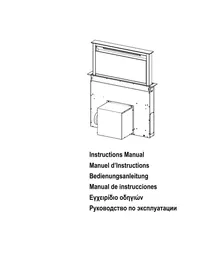



| Product type | Built-in cooker hood |
| Brand | FABER |
| Model | FABULA |
| Power supply | 220-240 V, 50/60 Hz |
| Maximum power | Up to 12.4 kW (compatible with certain gas hobs) |
| Minimum safety distance | 650 mm between hood and hob |
| Air outlet diameter | 120 mm or 150 mm |
| Suction speeds | 4 speeds + intensive |
| Delay function | Delayed shutdown of 30 minutes |
| Lighting | White LED, class 1M, max power 7 W |
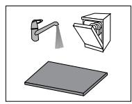
| Grease filters | Washable metal (dishwasher), clean every 2 months |
| Activated charcoal filter | Replace every 4 months, not washable |
| Saturation alarm | Yes, for grease filters (100h) and charcoal (200h) |
| Remote control | Optional (LR03 AAA batteries not included) |
| Weight | Approximately 15 kg (estimate) |
| Dimensions (W x D x H) | Approximately 90 x 50 x 30 cm (estimate) |
Frequently Asked Questions - FABULA FABER
User questions about FABULA FABER
0 question about this device. Answer the ones you know or ask your own.
Ask a new question about this device
Download the instructions for your Air conditioner in PDF format for free! Find your manual FABULA - FABER and take your electronic device back in hand. On this page are published all the documents necessary for the use of your device. FABULA by FABER.
USER MANUAL FABULA FABER
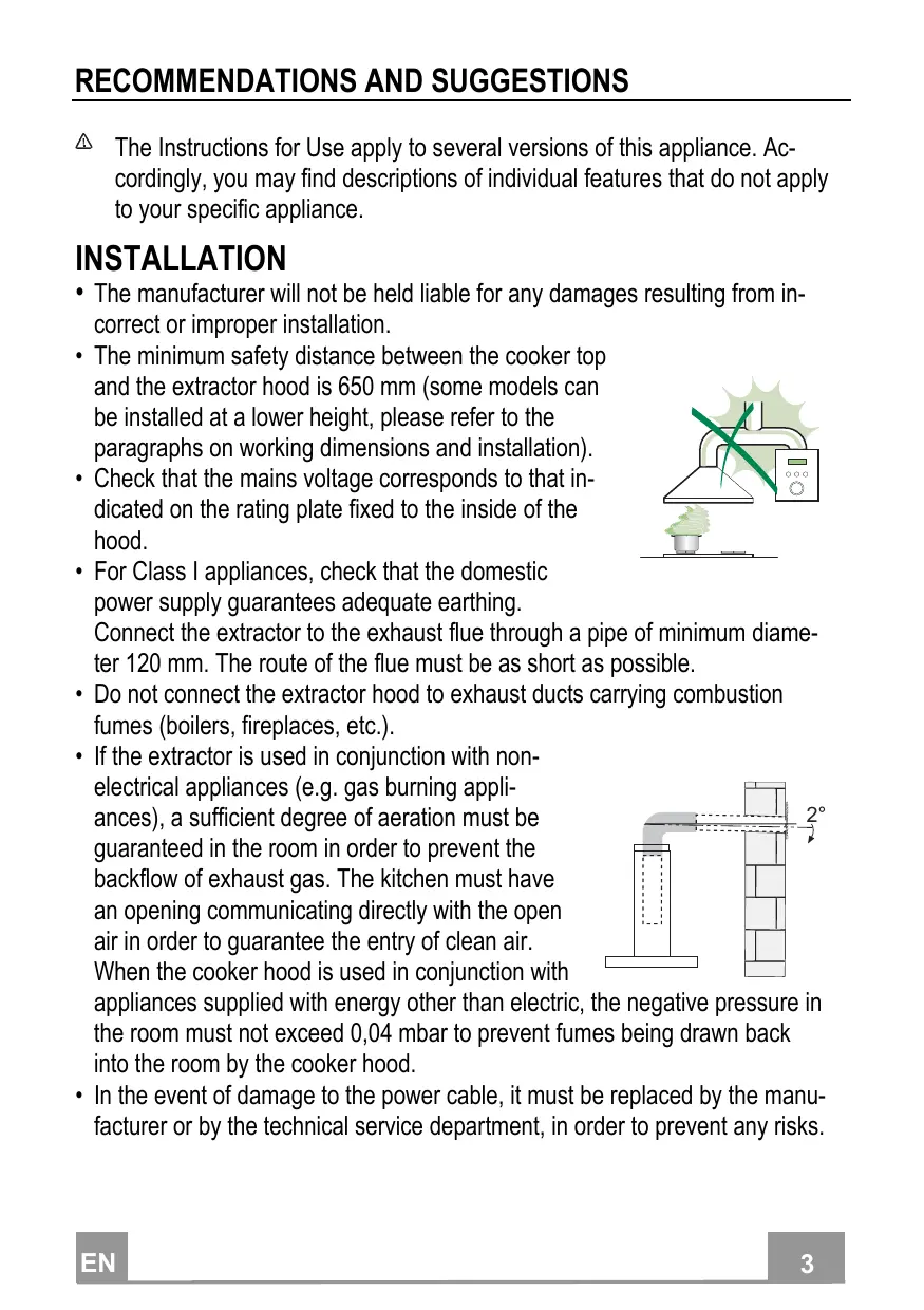
The Instructions for Use apply to several versions of this appliance. Accordingly, you may find descriptions of individual features that do not apply to your specific appliance.
INSTALLATION
- The manufacturer will not be held liable for any damages resulting from incorrect or improper installation.
- The minimum safety distance between the cooker top and the extractor hood is 650 mm (some models can be installed at a lower height, please refer to the paragraphs on working dimensions and installation).
- Check that the mains voltage corresponds to that indicated on the rating plate fixed to the inside of the hood.
- For Class I appliances, check that the domestic power supply guarantees adequate earthing.
Connect the extractor to the exhaust flue through a pipe of minimum diameter 120 mm. The route of the flue must be as short as possible.
- Do not connect the extractor hood to exhaust ducts carrying combustion fumes (boilers, fireplaces, etc.).
- If the extractor is used in conjunction with nonelectrical appliances (e.g. gas burning appliances), a sufficient degree of aeration must be guaranteed in the room in order to prevent the backflow of exhaust gas. The kitchen must have an opening communicating directly with the open air in order to guarantee the entry of clean air. When the cooker hood is used in conjunction with
appliances supplied with energy other than electric, the negative pressure in the room must not exceed 0.04 mbar to prevent fumes being drawn back into the room by the cooker hood.
- In the event of damage to the power cable, it must be replaced by the manufacturer or by the technical service department, in order to prevent any risks.
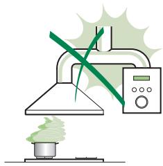
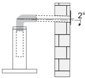
- If the instructions for installation for the gas hob specify a greater distance than the one specified above, this has to be taken into account. Regulations concerning the discharge of air have to be fulfilled.
- Use only screws and small parts in support of the hood.
Warning: Failure to install the screws or fixing device in accordance with these instructions may result in electrical hazards.
- Connect the hood to the mains through a two-pole switch having a contact gap of at least 3 mm.
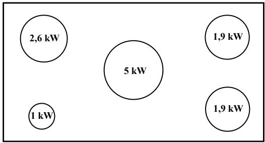
- This cooker hood can be used in conjunction with a gas cooktop having
the following characteristics:
Maximum power 12.4 kW - 5 burners as shown in the picture.
USE
- The extractor hood has been designed exclusively for domestic use to eliminate kitchen smells.
- Never use the hood for purposes other than those for which it has been designed.
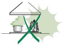
- Never leave high naked flames under the hood when it is in operation.
- Adjust the flame intensity to direct it onto the bottom of the pan only, making sure that it does not engulf the sides.
- Deep fat fryers must be continuously monitored during use: overheated oil can burst into flames.
- Do not flambé under the range hood; risk of fire.
- This appliance can be used by children aged from 8 years and above and persons with reduced physical,
sensory or mental capabilities or lack of experience and knowledge if they have been given supervision or instruction concerning use of the appliance in a safe way and understand the hazards involved. Children shall not play with the appliance. Cleaning and user maintenance shall not be made by children without supervision.
- “CAUTION: Accessible parts may become hot when used with cooking appliances.”
Switch off or unplug the appliance from the mains supply before carrying out any maintenance work.
- Switch off or unplug the appliance from the mains supply before carrying out any maintenance work.
- Clean and/or replace the filters after the specified time period (fire hazard).
- The grease filters must be cleaned every 2 months of operation, or more frequently for particularly heavy usage, and can be washed in a dishwasher.
- The activated charcoal filter is not washable and cannot be regenerated, and must be replaced approximately every 4 months of operation, or more frequently for particularly heavy usage.
- Clean the hood using a damp cloth and a neutral liquid detergent.
The symbol on the product or on its packaging indicates that this product may not be treated as household waste. Instead it shall be handed over to the applicable collection point for the recycling of electrical and electronic equipment. By ensuring this product is disposed of correctly, you will help prevent potential negative consequences for the environment and human health, which could otherwise be caused by inappropriate waste handling of this product. For more detailed information about recycling of this product, please contact your local city office, your household waste disposal service or the shop where you purchased the product.
Components
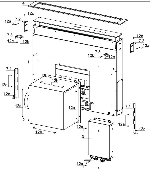
| Ref. | Q.ty | Product Components |
| 1 | 1 | Hood Canopy complete with: Controls, Light, Filters |
| 2 | 1 | Motor unit |
| 3 | 1 | Electric unit |
| 4 | 1 | Front Frame |
| Ref. | Q.ty | Installation Components |
| 7.1 | 2 | Splashback Fixing Bracket |
| 7.2 | 2 | Hob Fixing Bracket |
| 7.3 | 2 | Side Bracket |
| 12a | 16 | Screws 3.5 x 9.5 |
| 12b | 6 | Screws M4 x 8 |
| 12c | 6 | Screws 4 x 15 |
| Q.ty | Documentation | |
| 1 | Instruction Manual |
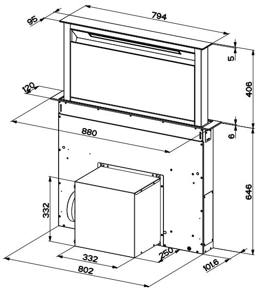
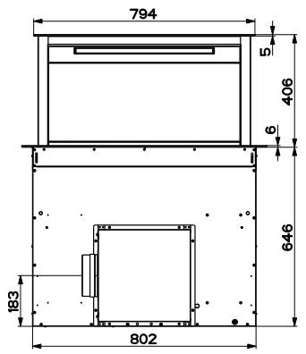
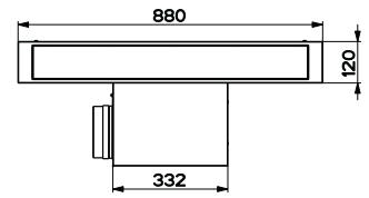
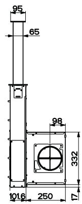
This hood is set up to be fitted inside the kitchen unit in:
Ducting version:
Evacuation to the outside.
- Recirculation version:
Internal recirculation.
Sequence of operations - Installation
- Drilling the support surface and fitting the hood
- Connections functional check
- Disposal of packaging
Drilling the Support Surface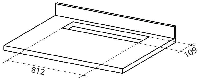
IMPORTANT
The minimum distance between the opening for the hob and the one for the hood must be at least 3-5 cm, depending on the strength of the material used for the worktop.
- The hood is built ready for front installation of the motor unit.
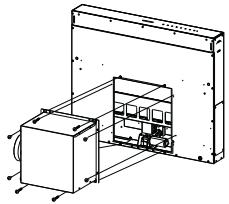
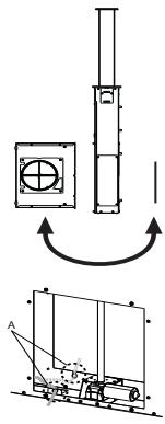
- If the kitchen unit is arranged differently and the motor unit has to be fitted at the back, the plug already fitted on the back of the hood canopy must be removed and replaced at the front, and the cable with cable raceway for connection of the motor must also be repositioned using the slot provided on each side (A).
Before proceeding, the motor unit must be fixed to the hood canopy (see paragraph on Fixing the Motor Unit).
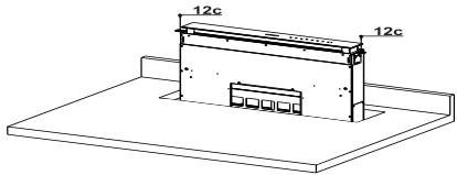
- Insert the hood canopy from below into the support worktop, drilled as described above.
- With the aid of a support, lift the hood canopy until the front comes out of the worktop.
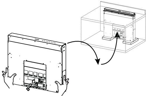
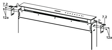
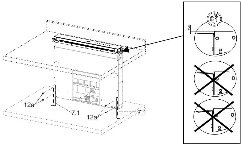
- Insert the brackets 7.2, as indicated in the figure, into the slots provided and fix them with the screws 12a provided.
- Centre the hood canopy with respect to the cooking hob slot.
- Using the 2 screws 12c provided, fix the hood canopy to the worktop and remove the supports.
Warning:
If the cooker top is made from a material that does not allow the screws 12c to be inserted, use a small amount of silicone to glue the brackets 7.2 to the top and allow it to dry completely before proceeding with installation.
- Insert the Brackets 7.2, as indicated in the figure, into the slots provided and fix them with the screws 12a provided.
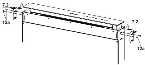
- The Hood is now ready for front installation of the Motor Unit.
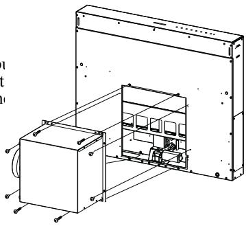
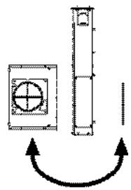
- If the kitchen unit is arranged differently and the Motor Unit has to be fitted on the back, the Plug already fitted on the back of the Hood Canopy must be removed and replaced at the front, and the Cable with cable raceway for connection of the Motor must also be repositioned using the slot provided on each side (A).
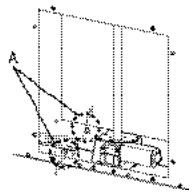
- Insert the Hood Canopy into the cooker top, drilled as described above.
- Centre the Hood Canopy with respect to the Cooking Hob slot. Fix the Hood Canopy with the 2 screws 12c provided.
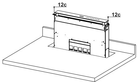
Warning:
If the cooker top is made from a material that does not allow the screws 12c to be inserted, use a small amount of silicone to glue the Brackets 7.2 to the top and allow it to dry completely before proceeding with installation.
- Screw the brackets 7.1 to the front of the Hood Canopy using the screws 12a provided.
- Before tightening the Brackets completely, make all the adjustments to allow them to rest on the lower base of the worktop to avoid deformation of the upper brackets 7.2 as shown in the figure.
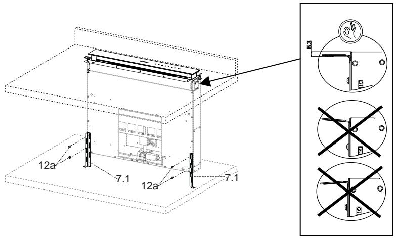
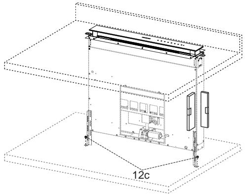
- With the aid of a spirit level, set the Hood Canopy level vertically and fix it to the Lower Surface using 2 screws 12c provided.
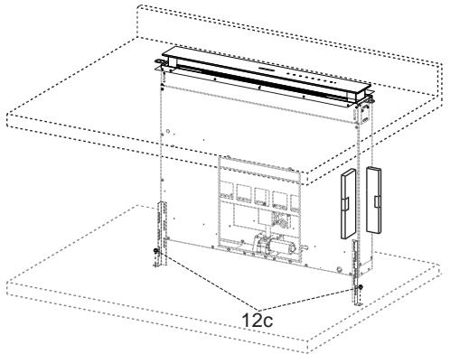
- Tighten the screws 12a completely.
- Screw the brackets 7.3 to the Hood Canopy using the screws 12b provided, without tightening completely.
- Using the screws 12c provided, fasten the other part of the brackets 7.3 either to the side walls of the unit or to the lower part of the cooker top.
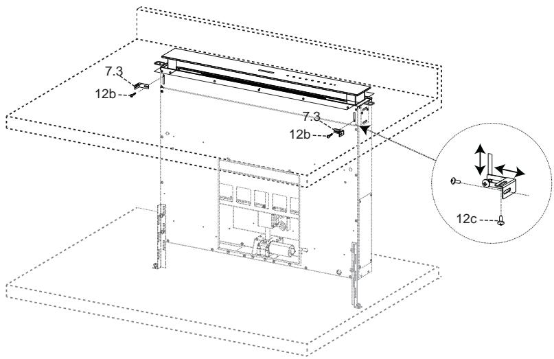
- Tighten the screws 12c and 12b completely.
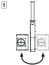
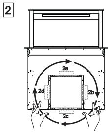
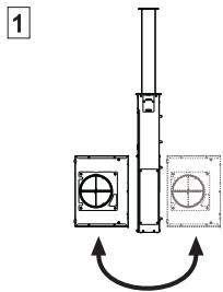
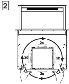
- Installation of the Motor Unit (1) at the front or rear must be decided according to the position of the Kitchen unit, making sure that the plug is properly positioned.
- Subsequently, according to where the air outlet opening has been created on the unit, the Motor Unit can be turned by 90° at a time so as to allow the air to come out on all 4 sides in correspondence with the opening in Unit (2).
- Connect the connector from the Hood Canopy to the Motor Unit connection.
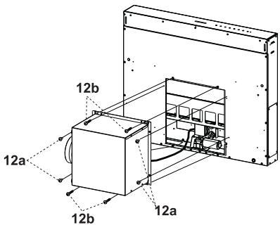
- Screw the Motor Unit to the Hood Canopy using the screws 12a and 12b provided as shown in the figure.
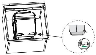
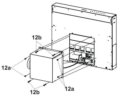
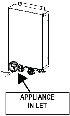
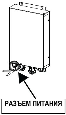
- Connect the Electric cables that come out of the lower right hand part of the Hood Canopy to the Connectors on the Electric unit. Each cable connector has a corresponding connector on the Electric Unit, so take care not to make mistakes when connecting up.
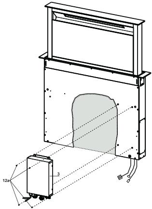
Fix the Electric Unit to the Hood Canopy using the screws 12a provided. - The position indicated in the figure is only an option, as if necessary it may also be fitted on the left of the Hood Canopy or even left free on the base of the unit if there are no structural or safety problems involved.
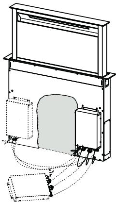
Warning.: Do not install the product in such a way that the wiring box is in contact with the floor.
DUCTED VERSION AIR EXHAUST SYSTEM
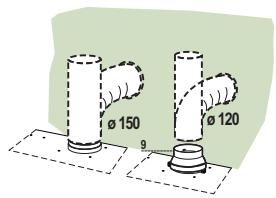
When installing the ducted version, connect the hood to the chimney using either a flexible or rigid pipe Ø150 or 120 mm, the choice of which is left to the installer.
- To install a Ø120 mm air exhaust connection, insert the reducer flange 9 on the hood body outlet. Fix the pipe in position using sufficient pipe clamps (not supplied).
- Remove possible charcoal filters.
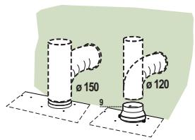
AIR OUTLET - RECIRCULATION VERSION
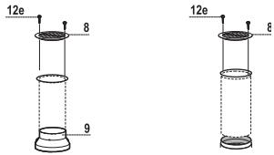
- Connect the flange to the air outlet opening using a rigid or flexible pipe of Ø120 or 150 mm.
- To connect using a Ø120 mm pipe, insert the reduction flange 9 onto the hood canopy outlet.
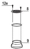
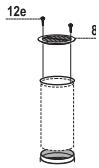
- Fasten the pipe using suitable pipe clamps. The materials required to do so are not provided. Fix the directional grid 8 on the outlet, using 2 screws 12e (2.9 x 9.5) provided.
- Make sure that the activated charcoal filters are present (see paragraph on Activated Charcoal Filter Maintenance).
ELECTRICAL CONNECTION
- Connect the hood to the mains through a two-pole switch having a contact gap of at least 3 mm.
- Lift the mobile hood canopy (see paragraph on Use) by just a few centimetres.
- To stop movement, simply press down on the mobile canopy as it lifts up.
Warning: Never block the sliding door when it is opening or closing, except during the operations required to fit the frame.
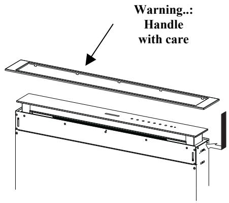
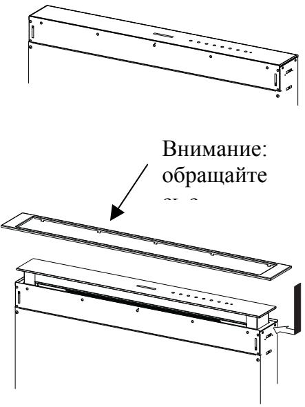
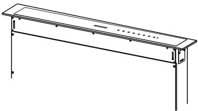
- Remove the sponge guards from the corners of the glass. Take the front frame and insert it from above, making sure that its tabs insert into the slots provided on the hood and sliding it to the left.
Warning... All the tabs must be inserted.
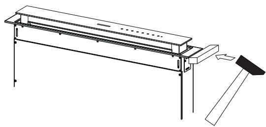
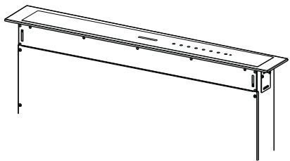
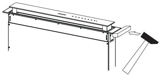
- Use a tool (hammer) to tap all along the front frame from right to left until it is completely flush. A piece of wood or similar element can be inserted between the hammer and the front frame to prevent any damage.
- Please refer to the paragraph on Use for indications of how to return the mobile canopy to the standard position.
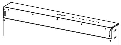
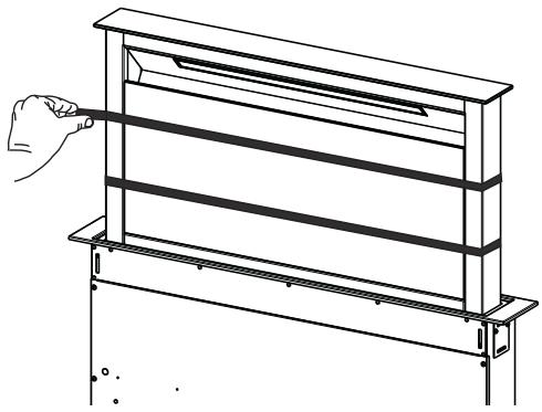
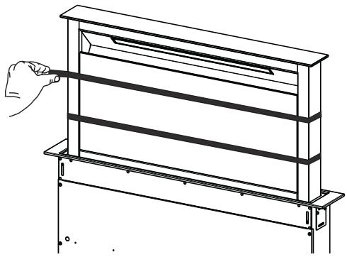
- Open the hood door (see USE).
- Remove the 2 strips of adhesive tape fastening the panel during transport.

A

B

C

D

E

F

G

H
Control panel
| Button | Function | LED button |
| A | The button only works when the door is open. | |
| Press Briefly = Turns the Lights On/Off at maximum intensity. | ||
| Press and hold for 2 Seconds = Turns the Courtesy Lights On/Off. | ||
| B | Only works with the Door Open. Press briefly = Activates/Deactivates Delay mode, causing automatic shutdown of the Motor and the Lighting system from any speed with a 30° delay. It is disabled by pressing the same button again, turning the motor off or closing the door. | LED Button B+ Button for the set Speed are lit. |
| Works both with the Door Closed and Open. Press and hold for 2 Seconds = With the filter alarm triggered the Filter Alarm is Reset, all leds flashing 3 times. These indications are only visible when the motor is turned off. | Fixed LED button: Indicates the need to wash the metal grease filters. The alarm is triggered after the Hood has been in operation for 100 working hours. Flashing LED button: Indicates the need to change the activated charcoal filters, and also to wash the metal grease filters. The alarm is triggered after the Hood has been in operation for 200 working hours. | |
| C | Only works with the Door Open. Press briefly = Activates speed four. | Fixed LED button |
| Only works with the Door Open. Press and hold for 2 seconds = Enables/Disables the Intensive speed. This speed is timed to run for 6 minutes. At the end of this time the system will return to the speed set previously. It is disabled by pressing the same button again, turning the motor off or closing the door. | Flashing LED button | |
| D | Only works with the Door Open. Activates speed three. | Fixed LED button |
| E | Only works with the Door Open Activates/Deactivates speed two. | Fixed LED button |
| Works both with Door Closed and Open with Motor + Lights = Off. Press and hold for 4 Seconds = Enables/disables the Keyboard lock. | All the LED buttons flash twice. During the Lock the LED buttons light up in sequence. | |
| F | Only works with the Door Open. Press briefly = Activates/Deactivates speed one. | Fixed LED button |
| Door Open or Closed Press and hold for 2 Seconds = Enables/Disables the Activated Charcoal Filter Alarm with the Motor turned off and no Filter Alarm triggered. | LED button B flashes twice = Activated Charcoal filter Alarm Activated LED button B flashes once = Activated Charcoal filter Alarm Deactivated | |
| G | Door Open Press briefly = Turns the Motor off | LED button goes out |
| Door Open or Closed Press and hold for 2 Seconds with Motor and Lights Off = Enables/Disables the Remote control. | LED button G + F flashes twice = Remote control Enabled LED button G + F flashes once = Remote control Disabled | |
| H | Door Open = Closes the Door + Lights and Motor Off Door Closed = Opens the Door + Lights and Motor On. Warning: If the Door remains partially open for any reason, press the Button to complete the opening or closing cycle. |
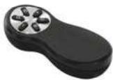
REMOTE CONTROL (OPTIONAL)
The appliance can be controlled using a remote control powered by a 1.5 V carbon-zinc alkaline batteries of the standard LR03-AAA type (not included).
- Do not place the remote control near heat sources.
- Used batteries must be disposed of in the proper manner.
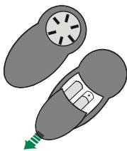
Remote control panel
Warning: The remote control receiver is deactivated when first supplied. To activate it, see the paragraph Use Function of Button G.
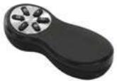
| Motor | Door Closed: Opens the door, turns the motor on at speed one and turns the lights on at maximum intensity. |
| Door Open: Brief pressure: Motor On / Off Pressed for 2 Seconds: Closes the Door and Motor + Lights = Off | |
| - | Only with Door Open: Decreases the working speed each time it is pressed. |
| + | Only with Door Open: Increases the working speed each time it is pressed. |
| ① | Intensity |
| ② | Delay |
| Light | Only with Door Open: Brief pressure: Lights On / Off Pressed for 2 Seconds: Courtesy lights On / Off |
Cleaning the Comfort Panels
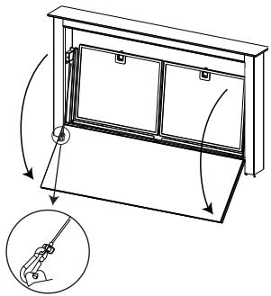
- Open the Comfort Panel by pulling it at the top.
- Unhook the security chain by opening the spring catch.
- Disconnect the panel from the hood canopy.
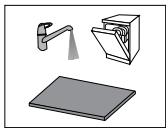
- The comfort panel must never be washed in the dishwasher.
- Clean the outside with a damp cloth and neutral detergent.
- Clean the inside using a damp cloth and neutral detergent; do not use wet cloths or sponges, or jets of water; do not use abrasive substances.
- On completing the operation, hook the panel and the spring catch up to the hood canopy again and close it.
Metal grease filters
These can also be washed in the dishwasher, and need to be cleaned whenever button B lights up or at least once every 2 months use, or more frequently if use is particularly intensive.
Resetting the alarm signal
- Turn the Lights and the Suction Motor off.
- Press and hold button B for 2 seconds.
Cleaning the Filters
- Open the Door (see USE).
- Open the Comfort panel by pulling it.
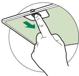
- Remove the filters one at a time, pushing them towards the back of the unit and simultaneously pulling downward.
- Wash the filters without bending them, and leave them to dry completely before replacing. (If the surface of the filter changes colour over time, this will have absolutely no effect on the efficiency of the filter itself.)
- Replace, taking care to ensure that the handle faces forwards.
- Close the Comfort panel.

Can be washed in the dishwasher. It must be washed when button B flashes or at least once every 4 months, or more frequently if use is particularly intense. Guaranteed to operate after washing for up to a maximum of 5 times before requiring replacement. The alarm signal, if it has been activated, only appears when the suction motor is turned on.
Activating the alarm signal
- In recirculation version hoods, the filter saturation alarm must be activated on installation or at a later date.
- Turn the lights and the suction motor off.
- Press and hold button F for 2 seconds:
- LED B flashes twice - Activated charcoal filter saturation alarm ACTIVATED.
- LED B flashes once - Activated charcoal filter saturation alarm DEACTIVATED.
CHANGING THE ACTIVATED CHARCOAL FILTER
Resetting the alarm signal
- Turn the Lights and the Suction Motor off.
- Press and hold button B for 2 seconds.
Changing the Filter
- Remove the comfort panel.
- Remove the Metal grease filters.
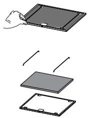
- Remove the metal filter stops from the grease filter and clean the saturated activated charcoal odour filter.
- Replace the clean activated charcoal odour filter, hooking it back up to the grease filter using the metal filter stops.
- Replace the Metal grease filters.
- Close the comfort panel.

Lighting unit
Warning: This appliance is fitted with a white LED lamp classed as 1M according to EN 60825-1: 1994 + A1:2002 + A2:2001 standards; maximum optical power emitted @439nm: 7µW . Do not look directly at the light through optical devices (binoculars, magnifying glasses...).
- For replacement contact technical support. ("To purchase contact technical support")
Evacuation external.
- Version filtrante
| Пдиро | Ал decorура | Пдиро Led |
| A | Торгиро л decorура моро мгглрглрглрглрглрглрглрглрглрглрглрглрглрглрглрглрглрглрглрглрглрглрглрглрглрглрглрглрглрглрглрглрглрглрg | |
| Σдиро моро = Адиро/2Диро = Адиро/2Диро = Адиро/2Диро = Адиро/2Диро = Адиро/2Диро = Адиро/2Диро = Адиро/2Диро = Адиро/2Диро = Адиро/2Диро = Адиро/2Диро = Адиро/2Д四种/2Д四种/2Д四种/2Д四种/2Д四种/2Д四种/2Д四种/2Д四种/2Д四种/2Д四种/2Д四种/2Д四种/2Д四种/2Д四种/2Д四种/2Д四种/2Д四种/2Д四种/2Д四种/2Д四种/2Д四种/2DA四种/2DA四种/2DA四种/2DA四种/2DA四种/2DA四种/2DA四种/2DA四种/2DA四种/2DA四种/2DA四种/2DA四种/2DA四种/2DA四种/2DA四种/2DA四种/2DA四种/2DA四种/2DA四种/2DA四种/2DA四种/2DA四种/2DA四种/2DA四种/2DA四种/2D四种/2DA四种/2DA四种/2DA四种/2DA四种/2DA四种/2DA四种/2DA四种/2DA四种/2DA四种/2DA四种/2DA四种/2DA四种/2DA四种/2DA四种/2DA四种/2DA四种/2DA四种/2DA四种/2DA四种/2DA四种/2DA四种/2DA四种/2DA四种/2DA四种/2DB四种/2DB四种/2DB四种/2DB四种/2DB四种/2DB四种/2DB四种/2DB四种/2DB四种/2DB四种/2DB四种/2DB四种/2DB四种/2DB四种/2DB四种/2DB四种/2DB四种/2DB四种/2DB四种/2DB四种/2DB四种/2DB四种/2DB四种/2DB四种/2DB四种/2DA四种/2DA四种/2DA四种/2DA四种/2DA四种/2DA四种/2DA四种/2DA四种/2DA四种/2DA四种/2DA四种/2DA四种/2DA四种/2DA四种/2DA四种/2DA四种/2DA四种/2DA四种/2DA四种/2DA四种/2DA四种/2DA四种/2DA四种/2DA四种/2BA四种/2BA四种/2BA四种/2BA四种/2BA四种/2BA四种/2BA四种/2BA四种/2BA四种/2BA四种/2BA四种/2BA四种/2BA四种/2BA四种/2BA四种/2BA四种/2BA四种/2BA四种/2BA四种/2BA四种/2BA四种/2BA四种/2BA四种/2BA四种/2BA四种/2DA四种/2DA四种/2DA四种/2DA四种/2DA四种/2DA四种/2DA四种/2DA四种/2DA四种/2DA四种/2DA四种/2DA四种/2DA四种/2DA四种/2DA四种/2DA四种/2DA四种/2DA四种/2DA四种/2DA四种/2DA四种/2DA四种/2DA四种/2DA四种/2MA四种/2MA四种/2MA四种/2MA四种/2MA四种/2MA四种/2MA四种/2MA四种/2MA四种/2MA四种/2MA四种/2MA四种/2MA四种/2MA四种/2MA四种/2MA四种/2MA四种/2MA四种/2MA四种/2MA四种/2MA四种/2MA四种/2MA四种/2MA四种/2MA四种/2DA四种/2DA四种/2DA四种/2DA四种/2DA四种/2DA四种/2DA四种/2DA四种/2DA四种/2DA四种/2DA四种/2DA四种/2DA四种/2DA四种/2DA四种/2DA四种/2DA四种/2DA四种/2DA四种/2DA四种/2DA四种/2DA四种/2DA四种/2DA四种/2FA四种/2FA四种/2FA四种/2FA四种/2FA四种/2FA四种/2FA四种/2FA四种/2FA四种/2FA四种/2FA四种/2FA四种/2FA四种/2FA四种/2FA四种/2FA四种/2FA四种/2FA四种/2FA四种/2FA四种/2FA四种/2FA四种/2FA四种/2FA四种/2FA四种/2F 四六四六四六四六四六四六四六四六四六四六四六四六四六四六四六四六四六四六四六四六四六四六四六四六四六四六四六四六四六四六四六四六四六四六四六四六四六四六四六四六四六四六四六四六四六四六四六四六四六四六四六46六六六六六六六六六六六六六六六六六六六六六六六六六六六六六六六六六六六六六六六六六六六六六六六六六六六六六六六六六六六六六六六六六六六六六六六六六六六六六六六六六六六六六六六六六六六六六六六六六六六六八八八八八八八八八八八八八八八八八八八八八八八八八八八八八八八八八八八八八八八八八八八八八八八八八八八八八八八八八八八八八八八八八八八八八八八八八八八八八八八八八八八八八八八八八八八八八八八八八八八八 |
THALEXIPTHPO (IPOAIPETIKO)
The device 1 is supplied with a rechargeable battery 1.5 V type LR03-AAA (not included).
Do not place the device near heat sources. Do not throw the batteries into the environment, but only into the appropriate bins.
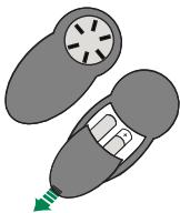
Battery indicator
Caution: The battery compartment cover is initially locked. To unlock it, see the section on using the device.
Unlock the device
- In the event of a power failure, the device's filter indicator will be activated automatically or in sequence.
- The light goes out and the motor stops. Press the F button for 2 seconds:
2 LED flashes - filter indicator active, device ON. 1 LED flash - filter indicator inactive, device OFF.
REPLACING THE ACTIVE CARBON FILTER
If the material from which the control panel is made does not allow screws 12c to be screwed in, use a small amount of glue to attach the brackets 7.2 to the panel, and let it dry thoroughly before continuing the installation.
- Attach the brackets 7.1 to the front of the extractor body using the screws 12a supplied.
- Before finally tightening the bracket screws, adjust their position so that they rest on the lower base of the roller, without deforming the upper brackets 7.2, as shown in the figure.
Using a level, align the extractor body vertically and secure it to the lower part with the 2 screws 12c supplied.
- Finally tighten the screws 12a.
- Attach bracket 7.3 to the extractor body using the screws 12b supplied in the kit, without tightening.
- Using the supplied screws 12c, attach the second half of brackets 7.3 to the side walls of the furniture or to the lower part of the countertop panel.
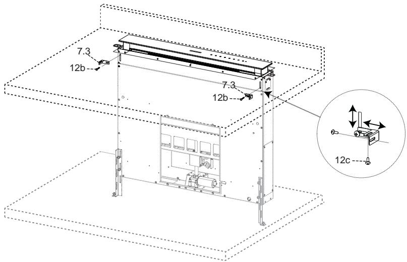
- Finally tighten screws 12c and 12b.
- The decision to install the motor (1) in front or behind depends on the structure of the furniture; in this case, make sure the gap is correct. Then, depending on the position of the exhaust air outlet in the motor housing, the motor can be rotated 90° so that air can exit from all 4 sides or align with the opening in the furniture (2).
- Connect the extractor body connector to the motor connector.
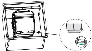
- Attach the motor to the extractor body using the supplied screws 12a and 12b, as shown in the figure.
Connect the electrical wires coming from the lower right side of the extractor body to the connectors of the distribution box. Each cable connector corresponds to a connector in the distribution box; be careful not to mix up their connections.
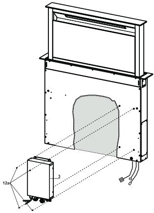
- Attach the distribution box to the extractor body using the screws 12a supplied in the kit. The position of the distribution box shown in the figure is indicative; it can be fixed on the left side of the extractor body or even left free on the floor, if this does not interfere with structural features or safety conditions.

Attention: Do not install the extractor so that the distribution box touches the floor.
Air exhaust from the suction extractor
For installation of the suction extractor, connect its outlet to a rigid or flexible duct with a diameter of 150 or 120 mm, which the installer can choose.
Long duct 120 mm to the exhaust outlet of the housing. Secure the duct with the appropriate duct clamps. Required mounting material is not included in the delivery. - Remove the odor filters from the activated carbon.
Exhaust air in filtration mode
- Connect the flange to the exhaust air outlet with a rigid or flexible duct 120 or 150 mm. - For connection with a duct 120 mm, insert the transition flange 9 into the exhaust outlet in the housing. Secure the duct with the special duct clamps. Required material is not included in the delivery. Secure the adjustable grille 8 on the air outlet 2 with the screws 12e (2.9 x 9.5) supplied in the kit.
- Check the presence of the odor filters with activated carbon (see section Maintenance of the activated carbon filters).
Electrical connection
Connect the extractor to the mains voltage, install a bipolar switch with a contact opening of at least 3 mm.
Lift the movable housing of the extractor (see section Operation) just a few centimeters. - To lock it in its movement, press the lifted housing downwards.
Attention: Never stop the movement of the hinged flap during opening or closing; this is only allowed during the installation of the frame.
- Remove the foam gaskets from the glass corners. Insert the intermediate frame from above; make sure that the tabs of the frame fit into the special openings on the extractor; slide the frame to the left. Attention: All tabs must be in the openings.
- To slide the intermediate frame under the hood, access it from the right with a suitable tool (hammer). To avoid damaging the frame, place a wooden block of appropriate size under the hammer. See section Operation to bring the movable housing of the extractor to the standard position.
- Open the flap of the extractor (see section Operation).
- Remove the 2 strips of adhesive tape that serve for safe transport of the panel.
A

B

C

D

E

F

G

H
Panaelb ynpablenia
Metal filters
The filters can also be washed in the dishwasher. They should be washed when the button lights up, or at least once every 2 months, or more often in case of particularly intensive use.
Alarm reset
Turn off the lighting and the motor of the suction system. Press the button for 2 seconds.
Cleaning the filters
- Open the flap (see operating instructions). Pull the handle and open the front panel of the hood. Remove the filters one by one. To do this, press them against the back wall of the hood and simultaneously push them down.
- Handle the filters carefully so that they do not bend, and let them dry before reinstalling. (Any change in the color of the filter surface over time does not affect the quality of their operation.) Put the filters back in place so that the handle is on the outer side. Close the front panel.
These filters are washable in the dishwasher. The filters must be cleaned when the button lights up, or at least once every 4 months, or more often in case of very intensive use. The effectiveness of the filters is maintained for no more than 5 washing cycles, after which the filters should be replaced. If the filter saturation indicator is in standby mode (active state), it only activates when the suction motor is turned on.
Activation of the indicator in standby mode
B BbIgKkax cpeKMOM peInpKyJIHHcIHHaJIH3aIIHHaHcJIbIeHnI φ HJIbTPOB IOJbKH aIKHeHa BAKTHBHoe COCTOJIHe) IIpH yCTAHOBKe HIN IIOJIe Hee. - BbIKIOHHTe OcBEIeHHe N IIBHrAteJIb BbITKHO BeHTINITTOPA. HaKMHTe KHOIIky F Ha 2 cekyHJIbI:
2 BCIIHIIHK INIINKATopA B-CHTHAIIN3aIIH NACIIHEHH yTOJIbHO rHIOBpBAKJIIOUeHA 1 BCIIbIIHa HINHINKaTOpa B-CnTHaJIH3aIHHaHcBIIeHReYrTOJIbHO rHbItpa BbIKJIOUOEAHA.
3AMEHA ΦЛьТРА ПИТМВ 3АПАХОВ HA AKТИВИРBAHHOM YTGJE
Cópoc abapniHoro cnHraJa
- BbIKJIIOHHTE OCBIEIeHHe IN DBHrAteJIb CHTeMb IBCaCbIBaHHN. HaKMHTeKHOIIkyB TeYeHne 2ceKyH.
Zameta hibtpa
CHIMITEIpeJIHOIOIIaHeJIb. BbIbTeMetaJIHTUHeCKHeKJIOBoBbIeΦJIbItpbI. C H M H T E M e t a J I U N C E K E N C h E f h K C a T o p b i c k h P O B O R O f h J I L T P a n O u C H T H T E H a c b l i e H H b i h f h J I L T P I P O T H B 3 a I A X O B H a a k T H B I N P o B a H H O M y T J I E. IIOCTaBbTe Ha MeCtO OUYHHeHb HINbTp IPOITb 3aIIaXOB Ha AKTHBnPoBaHHOM yTJe, CoeIHHB eTo fHKcTaOpamH C KInpOBbIM HJbTPOM. PiOCTaBbTe Ha MeTcO MetaJIuHcckHe JxHPOBbIe 0JIbIpbI. 3akpoitnepeepiHIOIaHeJIb.
OcBeUeHne
BHHMaHHe: IIpHbOp 6OBpyoBaH CBeToIOHOOM 6eIOrO IeBt AJIacca 1M COITACHO CTaHApTy EN 60825-1: 1994 + A1:2002 + A2:2001; MaKCHMaJIbHa MOnIOHocTb OHnueckOro H3IyueHHa @439nm: 7 MmKpOBaTT. He PeKOMeHuyetc CMOpTeH Na CBeTOIOHOjepe3 OHnueckHe IIpHbOpBy (6HNOKJB, yBeeHInrTeJIbHOe cTeKJIO HIpOu.).
- INSTALLATION
- USE
- SWITCH OFF OR UNPLUG THE APPLIANCE FROM THE MAINS SUPPLY BEFORE CARRYING OUT ANY MAINTENANCE WORK
- SEQUENCE OF OPERATIONS - INSTALLATION
- IMPORTANT
- WARNING
- DUCTED VERSION AIR EXHAUST SYSTEM
- AIR OUTLET - RECIRCULATION VERSION
- ELECTRICAL CONNECTION
- REMOTE CONTROL (OPTIONAL)
- REMOTE CONTROL PANEL
- CLEANING THE COMFORT PANELS
- METAL GREASE FILTERS
- RESETTING THE ALARM SIGNAL
- CLEANING THE FILTERS
- ACTIVATING THE ALARM SIGNAL
- CHANGING THE ACTIVATED CHARCOAL FILTER
- CHANGING THE FILTER
- LIGHTING UNIT
- THALEXIPTHPO (IPOAIPETIKO)
- BATTERY INDICATOR
- UNLOCK THE DEVICE
- REPLACING THE ACTIVE CARBON FILTER
- AIR EXHAUST FROM THE SUCTION EXTRACTOR
- EXHAUST AIR IN FILTRATION MODE
- METAL FILTERS
- ALARM RESET
- ACTIVATION OF THE INDICATOR IN STANDBY MODE
- AMEHA ΦЛЬТРА ПИТМВ 3АПАХОВ HA AKТИВИРBAHHOM YTGJE
- CÓPOC ABAPNIHORO CNHRAJA
- ZAMETA HIBTPA
- OCBEUEHNE
Brand : FABER
Model : FABULA
Category : Air conditioner