CONSTELLATION 1200 - Range hood ROBLIN - Free user manual and instructions
Find the device manual for free CONSTELLATION 1200 ROBLIN in PDF.

| Product type | Range hood |
| Brand | ROBLIN |
| Model | CONSTELLATION 1200 |
| Supply voltage | 220-240 V single-phase, 50/60 Hz |
| Protection class | Class 1 |
| Lighting power | LED module: 3.1 W (operation), 6.2 W max |
| Grease filters | Metallic, dishwasher safe (max 50°C), monthly |
| Odor filters | Optional: activated charcoal (replace every 3 months) or washable (clean every 2 months) |
| Number of speeds | Multiple speeds + intensive speed (6 minutes) |
| Control type | Touch electronic with display |
| Remote control | Included, pairing possible (activation by long press on ⏻) |
| Delayed shut-off function | 30 minutes |
| Clock function | No |
| Venting | Recirculation (with filters) or external venting |
| Interior cleaning | Once a year |
| Warranty | 2 years parts (excluding labor and travel) |
| Spare parts availability | 10 years from purchase date |
| Standards | CE (safety, EMC, ecodesign, RoHS directives) |
Frequently Asked Questions - CONSTELLATION 1200 ROBLIN
User questions about CONSTELLATION 1200 ROBLIN
0 question about this device. Answer the ones you know or ask your own.
Ask a new question about this device
Download the instructions for your Range hood in PDF format for free! Find your manual CONSTELLATION 1200 - ROBLIN and take your electronic device back in hand. On this page are published all the documents necessary for the use of your device. CONSTELLATION 1200 by ROBLIN.
USER MANUAL CONSTELLATION 1200 ROBLIN
Notice
CONSTELLATION
HOTTE DE PLAFOND
natural_image
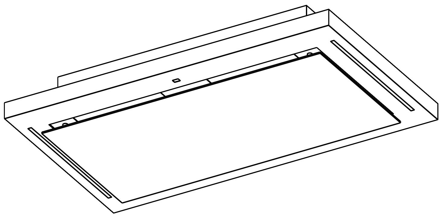
Isometric line drawing of a rectangular frame with internal cutouts and mounting holes (no text or symbols)FR Mode d'emploi et d'installation P. 4
GB Instructions for installation and use P. 8
DE Gebrauchs- und Installationsanleitung P. 12
IT Istruzioni per l'installazione e l'uso P. 16
ES Manual de empleo e instalación P. 20
NL Gebruiksaanwijzing en installatie P. 24
CH Suisse, cordon d'alimentation P. 28
Composants, Components, Komponenten, Componenti, Componentes, Onderdelen P. 29 Shéma électrique, Electrical diagram, Stromlaufplan, Schema elettrico, Esquema eléctrico, Elektrisch schema P. 30 Dessin technique, Technical drawing, Technische Zeichnung, Disegno tecnico, Dibujo técnico, Technische tekening P. 31 Montage, Assembly, Montage, Montaggio, Montaje, Montage P. 34 Entretien, Maintenance, Instandhaltung, Manutenzione, Mantenimiento, Onderhoud P. 39 Commande déportée, Remote controls, Hilfe bei der Diagnose, Comando deportato, Mando separado, Afstandsbediening P. 42 Commande, Controls, Bedienung, Comando, Mandos, Bediening, P. 43 Aide au diagnostic, Diagnostic aid, Zeichenerklärungen, Aiuto alla diagnostica, Ayuda a la diagnosis, Diagnosetabel P. 45 Légendes, Legends, Zeichenerklärungen, Legende, Leyendas, Legenda's P. 51
Version recyclage Recirculation version Umluftausführung Versione riciclo Versión recirculación Versie recirculatie
Version évacuation extérieure verticale Vertical exterior extraction version Vertikale Außenabluftausführung Versione evacuazione esterna e verticale Versión evacuación exterior vertical Versie verticale evacuatie naar buiten
Version évacuation extérieure horizontale Horizontal exterior extraction version Horizontale Außenabluftausführung Versione evacuazione esterna e orizzontale Versión evacuación exterior horizontal Versie horizontale evacuatie naar buiten

Version recyclage systeme «Clean-air» «Clean-air» system recirculation version Umluftausführung «Clean-air»-System Versione riciclo sistema «Clean-air» Versión sistema de recirculación «Clean-air» Versie “clean-air” recirculatie systeem
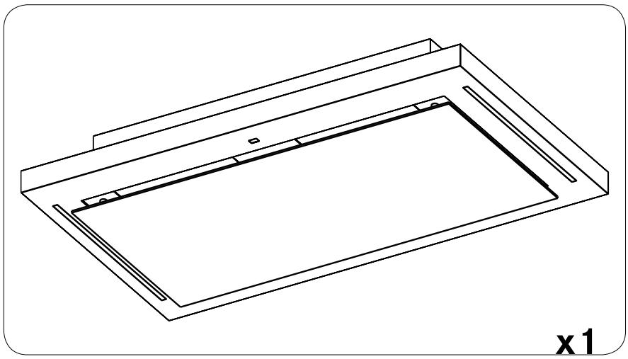
This manual applies to several appliance versions.
It may contain descriptions of accessories not included in your appliance.
THIS EQUIPMENT IS COMPLIANT WITH THE FOLLOWING STANDARDS:
EN 60 335-1:2012+A11:2014, EN 60 335-2-31:2014, EN 62233:2008 + C1:2008, EN 61 000-3-2:2006 + A1/A2: 2009, EN
61 000-3-3:2008, EN 55 014-1:2006 + A1:2009 + A2:2011, EN 55 014-2:1997 + A1:2001 + A2:2008, EN 61591:1997/
A2:2011, EN 50564:2011, EN 50581:2012, 2014/35/CE relating to electrical safety, 2014/30/EC relating to electromagnetic compatibility, 2009/125/EC relating to ecodesign, 2011/65/EC relating to the limitation of the use of certain hazardous substances in electrical and electronic equipment and to the main requirements of European Directives 66/2014.
When the symbol of a crossed out wheelie bin is attached to a product it means that the product is covered by the European Directive 2002/96/EC.
Your product is designed and manufactured with materials and components of high quality that can be recycled and used again:
- You should find out about the local system of separation of electrical and electronic waste,
You should act according to the local rules and not dispose of your used product with normal domestic waste,
Correct disposal of your old product will help prevent the potential negative consequences on the environment and human health.
This appliance must not be used by persons (including children) with diminished psychical, sensory or mental capacities, nor by persons not having the experience and knowledge of this type of appliance, unless they are under the control and the training of persons responsible for their safety. Children should be supervised to ensure that they do not play with the appliance.
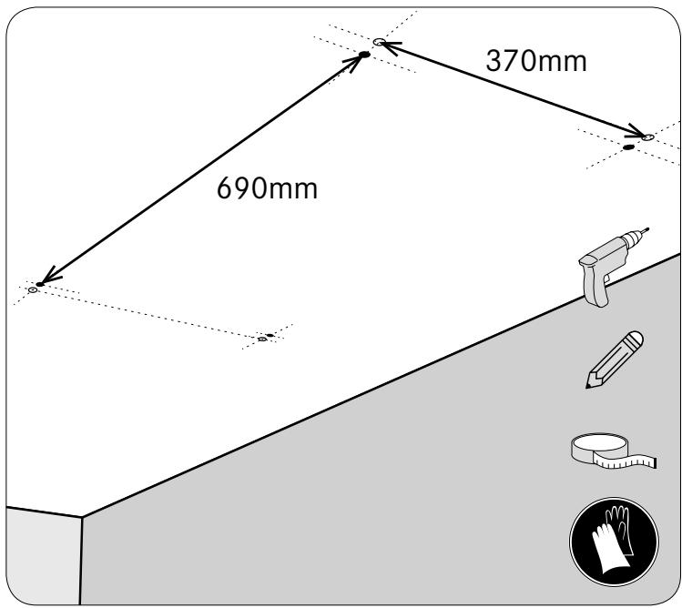
ASSEMBLY RECOMMENDATIONS

Assembly and connection must be done by a qualified installer ^(1) .
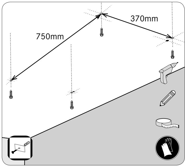
Use suitable anchors for the support medium. Obtain information from the manufacturers; seal if necessary. The company disclaims any responsibility in case of faulty anchoring due to the hole or the anchor system.
The hood is equipped with a HO5VVF 3 x 0.75 mm ^2 power cable with a standard 10/16A plug with earth.
Mode of protection: class 1
Supply voltage: 220-240V single phase - 50/60Hz.
Check that the mains voltage is the same as the values indicated on the manufacturer's plate on the inside of the hood.
If the hood is connected directly to the mains (without a plug), an all-pole circuit breaker switch with a contact opening of 3 mm must be installed before the hood. The earth wire (yellow and green) must not be broken by this switch.
- Respect the diameter of the appliance output: the hood must not in any circumstances be connected to a controlled mechanical ventilation duct.
- If it releases the stale air into an outlet duct, it is essential to ensure that the latter is not already used to carry gas or smoke from appliances powered by energy other than electricity.
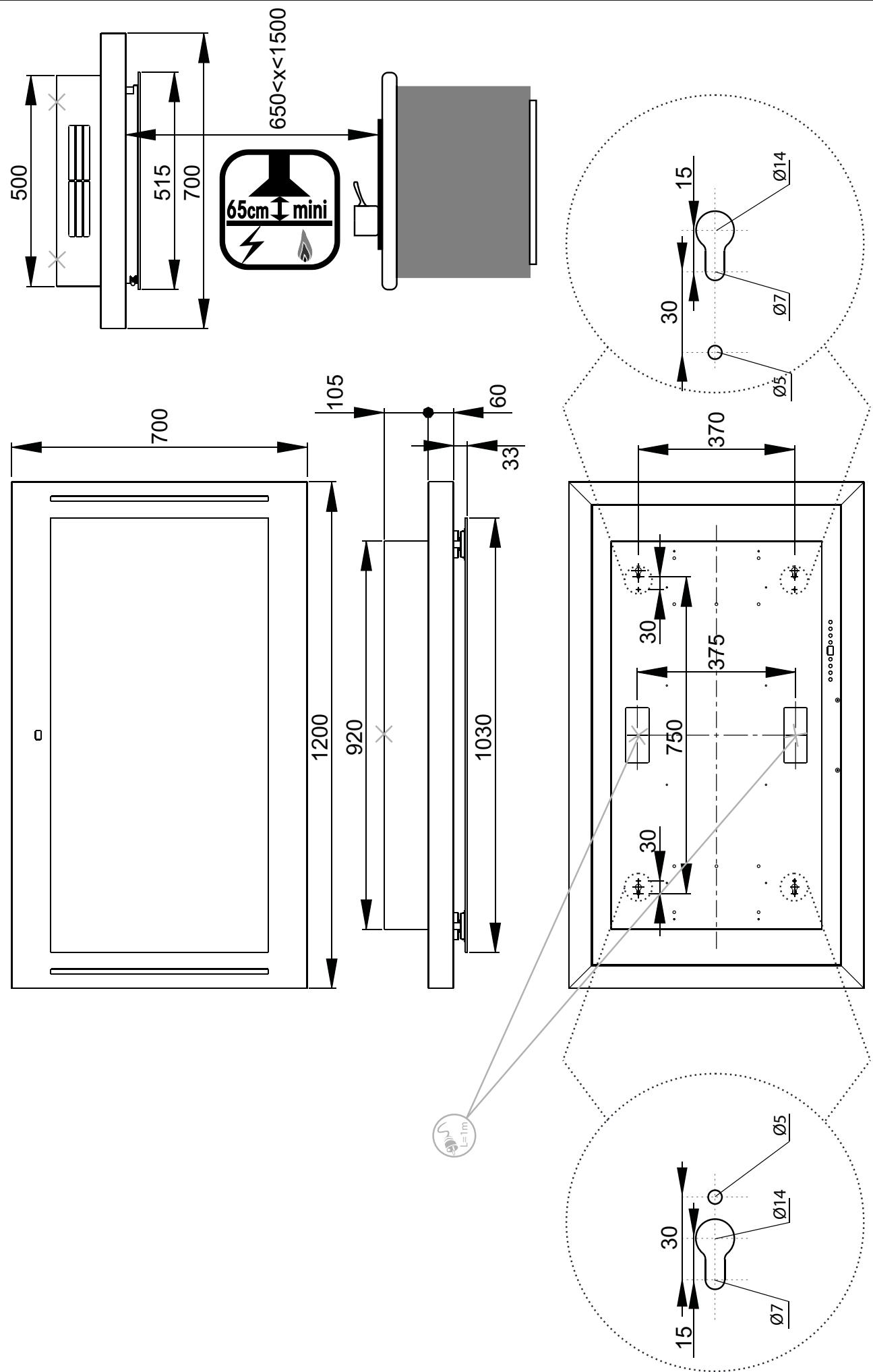
- Position the cooking surface as close as possible to the outlet and avoid the formation of elbows in the duct, to reduce pressure loss to the minimum.
- When installing situations, make sure that the air renewal in the kitchen is satisfactory. Be sure to create one or more air inlets with a section greater than or equal to the diameter of the outlet pipe in order not to create a vacuum in the kitchen.
- Make sure there is sufficient ventilation if a cooking or other appliance uses the ambient air of the room where the hood is installed at the same time.
- The maximum vacuum created in the room should be less than 0.04 mbar; this prevents return of the combustion gases.
- The appliance must be positioned in such a way that the power plug is accessible.
POWER SAVING TIPS
- Preferably use a low suction speed; only use the high speed if it is really necessary.
- A well ventilated kitchen makes hood operation more efficient.
- Clean the anti-grease filters regularly to maintain their efficiency.
- A saturated filter is not efficient and cannot be used for long.


RECOMENDATIONS FOR USE
NEVER FLAME DISHES UNDER THE APPLIANCE
Never leave open flames under the hood while it is operating.
Fried foods require a permanent monitoring, overheated oil may catch fire.
The accessible parts of the hood may become hot when it is used with cooking appliances.
To obtain maximum efficiency in the absorption of smoke or fumes, run the hood for approximately 5 minutes before and after cooking food:
- low speeds are recommended when cooking on a low heat and for sauces, simmering, etc.
• intermediate speeds are recommended for fast cooking, and fried or grilled foods.
• high speeds are recommended for cooking that creates a lot of fat or vapour.
• the extra fast speed is recommended in cases of sudden excessive release of vapours and fumes.

WARNING
CAUTION: This appliance (downflow extraction installation) is not intended to be used with gas cooking hobs, except if detailed information supplied with the hob stipulates the contrary.
RISK: Extinction of the cooking hob flames by a flow of air sucked by the hood flattening and stifling the flames.
Avoid fire risk by cleaning the hood according to the maintenance instructions :
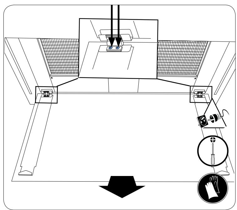
Turn the hood off before any maintenance operation or electrical work. Wear gloves.


- Clean the bodywork regularly using non-abrasive detergent products and a slightly damp sponge.
• To renovate external stainless steel parts (at intervals of one year minimum), it is preferable to use the product ref. 112.0172.941
• Never use soaked sponges or rags.. - Do not insert any object, or your hands, into the opening serving for the extraction of the air.
- Clean the inside of the extraction body once per year.
- Check the flow of stale air every 6 months.
- Observe local regulatory requirements covering the extraction of stale air.
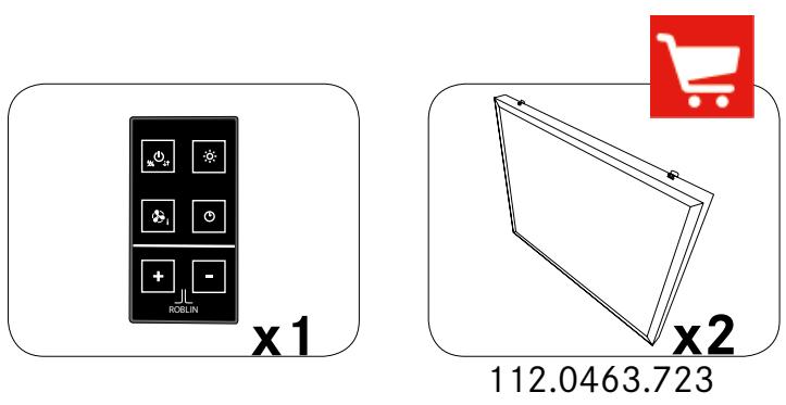
- It is essential to clean anti-grease filters in a dishwasher at a maximum temperature of 50^ C, once per month or according to the indications on the order (see order page). Allow the filters to dry in the open air. These filters have a service life of 10 years.


- If your hood is equipped with washable anti-odour filters ^(3) , they must be cleaned in a dishwasher at high temperature (without other kitchen utensils) every 2 months and dried by the dishwasher or in the open air for approximately 30 minutes.
- Once washed and dried, reactivate the washable anti-odour filters by placing them in an oven for 10 minutes at 100^ maximum. Cleaning of the washable anti-odour filters should systematically be accompanied by cleaning of the anti-fat filters.
- Active charcoal ^(3) anti-odour filters need replacement at least every 3 months, or more often if the hood is used more than 3 hours per day. Or according to the indications of the order (see the order page). Replacement of the active charcoal anti-odour filters should systematically be accompanied by cleaning of the anti-fat filters.

CLEAN-R
- The ultraviolet bulbs have a life expectancy of approximately 6000 hours. The life cycle of the clean-air filters (catalysts) follows that of the ultraviolet lamps.
- The replacement of an ultraviolet bulb (every 3 years) should systematically be accompanied by the replacement of the associated clean air filter.

- The replacement of faulty LEDs should only be done by a certified professional specialist.
WARRANTY AND AFTER-SALES SERVICE
IF AN ELECTRIC COMPONENT IS DAMAGED IT CAN ONLY BE REPLACED BY A REPAIR SHOP APPROVED BY THE MANUFACTURER BECAUSE SPECIAL TOOLS ARE REQUIRED.
• In the event of faulty operation notify your installer who will check the appliance and its connection.
- Disconnect the appliance completely.
- Always require the use of genuine spare parts (non-compliance with this requirement can compromise the safety of the appliance).
- When ordering spare parts, quote the serial number of the appliance (see on the page opposite) on the plate located inside the hood.
- Only the purchase invoice of the appliance can serve as proof for the implementation of the contractual warranty (this warranty does not cover consumables such as: lighting, filters, LEDs, etc.).
UK ELECTRICAL CONNECTION - ELECTRICAL REQUIREMENTS
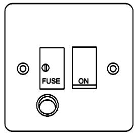
Any permanent electrical installation must comply with the lastet I.E.E Regulations and local Electricity Board regulations. For your own safety this should be undertaken by a qualified electrician e.g. your local Electricity Board, or a contactor who is on the roll of the National Inspection Council for Electrical Installation Contracting (NICEIC).
Before connecting to the mains supply ensure that the mains voltage corresponds to the voltage on the rating inside the cooker hood.
This appliance is fitted with a 2 core mains cable and must be permanently connected to the electricity supply
via a double-pole switch having 3mm minimum contact gap on each pole. A switched Fuse Connection Unit to BS.1363 Part 4, fitted with a 3 Amp fuse, is a recommended mains supply connection accessory to ensure compliance with the Safety Requirements applicable to fixed wiring instructions.
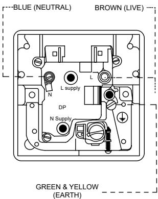
The wires in this mains lead are coloured in accordance with the following code :
Green & yellow : Earth
Blue : Neutral
Brown : Live
As the colours of the wires in the mains lead of this appliance may not correspond with the coloured markings identifying the terminals in your connection unit, proceed as follows :
The wire which is coloured blue must be connected to the terminal which is marked with the letter 'N' or coloured black.
The wire which is coloured brown must be connected to the terminal which is marked with the letter ‘L’ or coloured red.
BEFORE FITTING
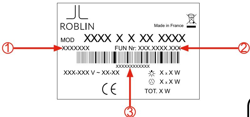
Copy and keep the references below
Check the label affixed to the body of the hood, inside, behind the filters. The information on this label is necessary for the After Sales Service assistance contact to provide technical assistance.
Assistance contact. Service Department: 04.88.78.59.93.
INFORMATION TO BE GIVEN TO THE SERVICE DEPT IN CASE OF NEED.
natural_image
Simple geometric diagram of a triangle inside a rectangle (no text or symbols)GLUE A COPY OF THE LABEL HERE
natural_image
Coiled black electrical plug with three terminal pins, isolated on white background (no text or symbols)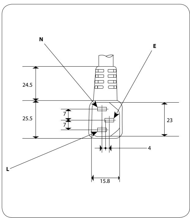
natural_image
Isometric line drawing of a rectangular frame with internal cutouts and mounting holes (no text or symbols)
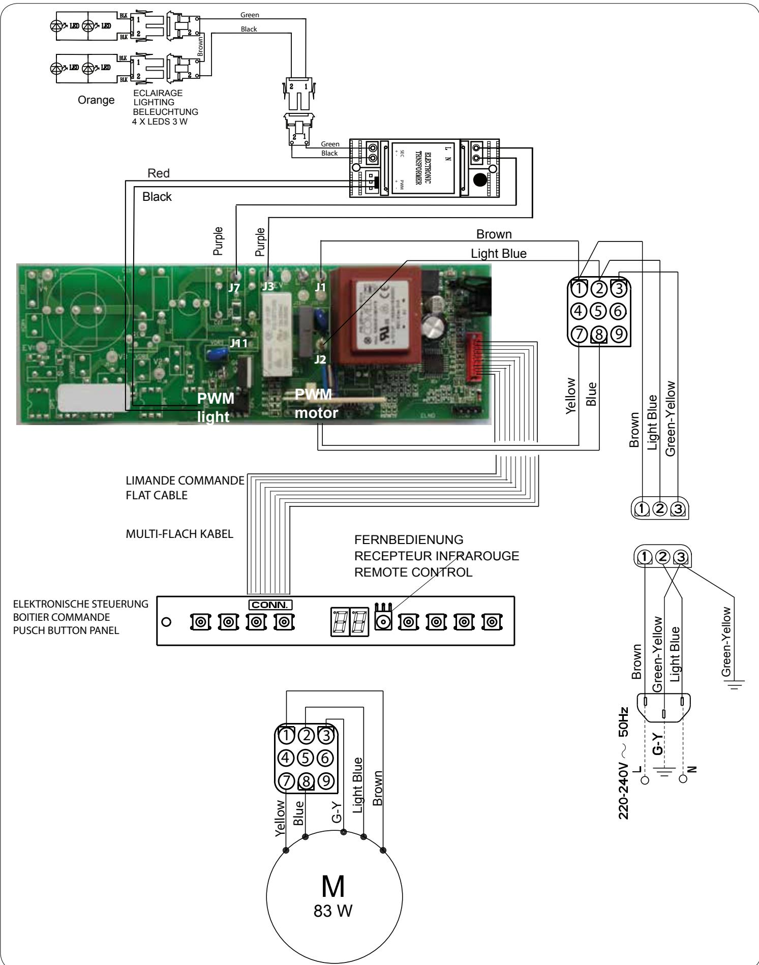
A : azur, azur, azur blau / BK : black, noir, schwarz / B : blue, bleu, blau / Br : brown, brun, braun / G-Y : green-yellow, vert-jaune, grün-gelb / Gr : grey, gris, grau / LB : light blue, bleu clair, hell blau / P : pink, rose, rosa / V : purple, mauve, malver farbig / R : red, rouge, rot / W : white, blanc, weiss / W-P : white-pink, blanc-rose, weiss-rosa / Y : yellow, jaune, gelb
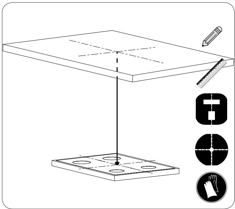
montage - fitting - Montage - montaggio - montaje - Montage
natural_image
Technical line drawing of a table with a stand and three inset icons (no text or symbols)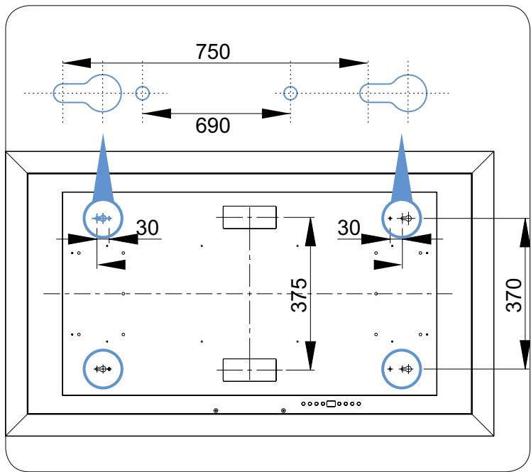
natural_image
Technical diagram of a mechanical assembly with labeled components (no text or symbols present)
natural_image
Diagram of a 3D printer or printer setup with a grid-patterned base and an arrow indicating rotation (no text or symbols)montage - fitting - Montage - montaggio - montaje - Montage
natural_image
Diagram of a printer or printer assembly with a blue tray and black cover, showing internal components and a magnified view (no text or symbols)
natural_image
Top-down schematic of a rectangular device with internal compartments and mounting points (no text or symbols)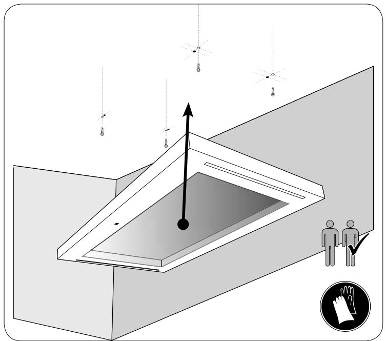
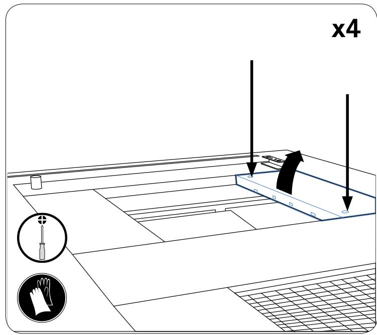
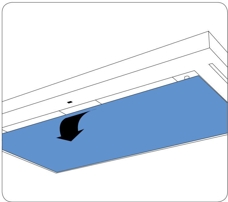
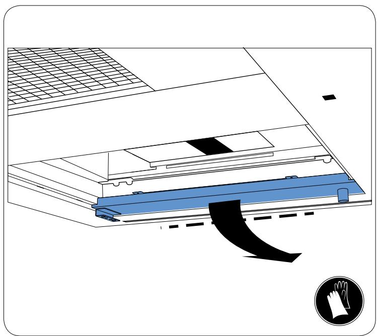
entretien - maintenance - Instandhaltung - manutenzione - mantenimiento - Onderhoud
natural_image
Diagram showing a blue platform with a black curved arrow pointing downward, mounted on a white structure (no text or symbols)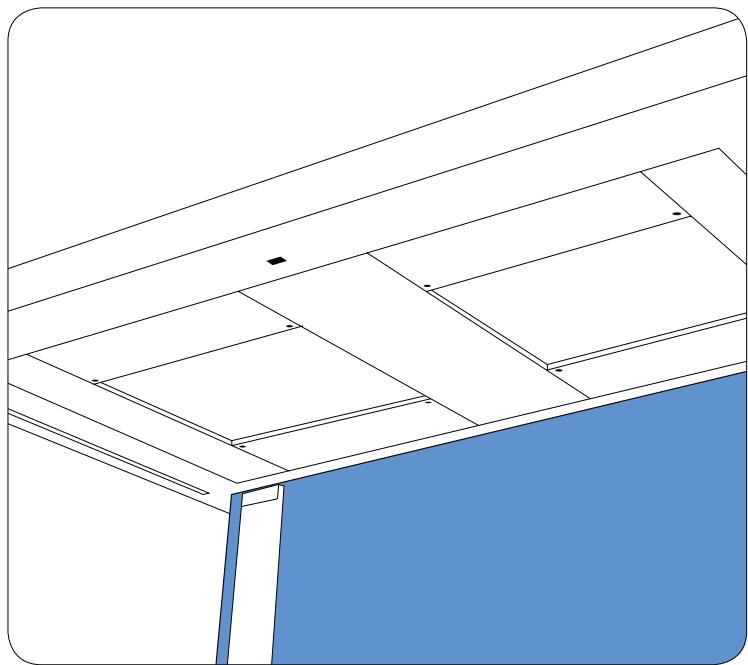
natural_image
Architectural diagram showing ceiling and floor panels with no text or symbols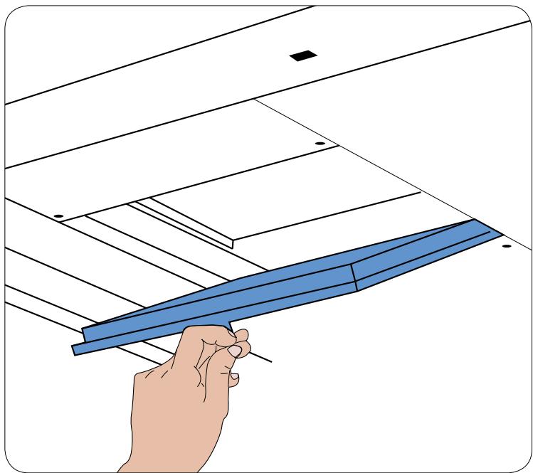
natural_image
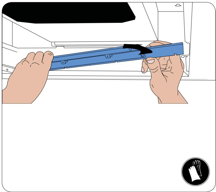
Illustration of a hand holding a blue metal beam against a ceiling structure (no text or symbols)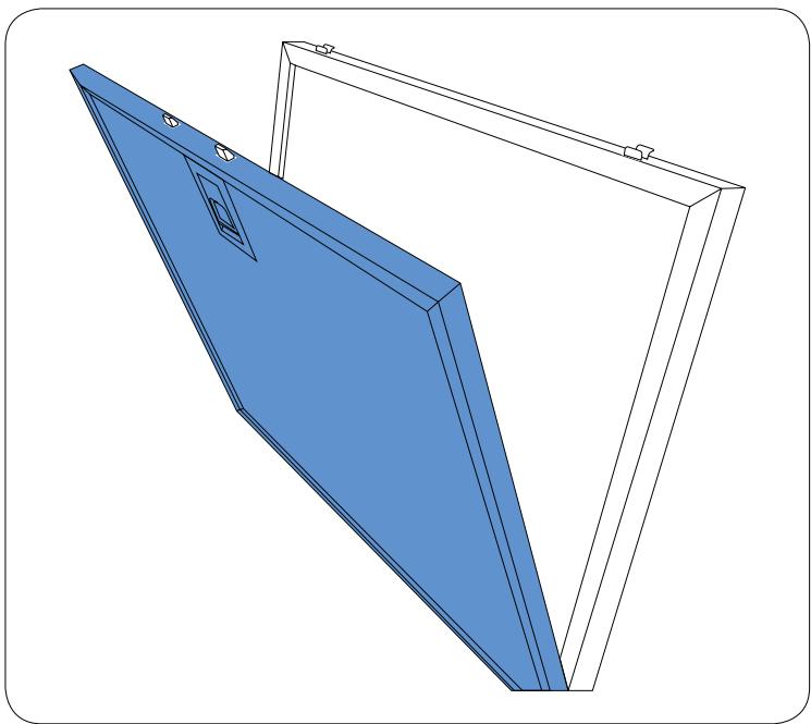
natural_image
3D technical illustration of a blue triangular panel mounted on a white frame, with mounting holes and a small inset slot (no text or symbols)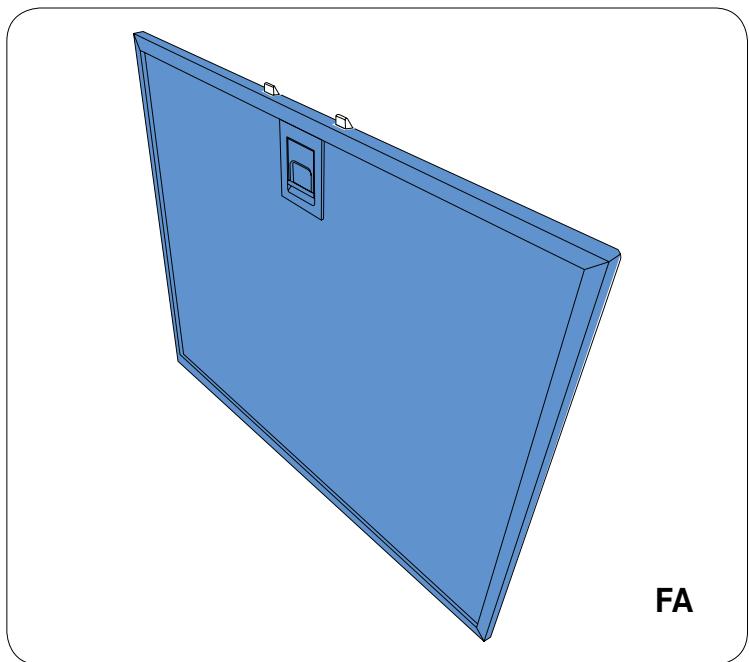
natural_image
3D rendering of a blue rectangular panel with a square recess and mounting bracket (no text or symbols)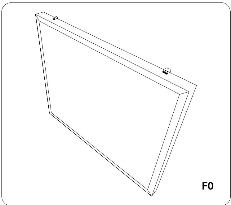
natural_image
Line drawing of a 3D rectangular frame with mounting holes and a label 'F0' (no other text or symbols)entretien - maintenance - Instandhaltung - manutenzione - mantenimiento - Onderhoud
natural_image
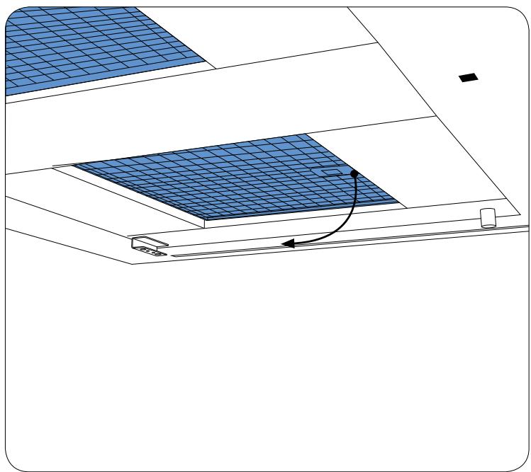
Diagram of a solar panel installation with grid pattern and directional arrow (no text or symbols)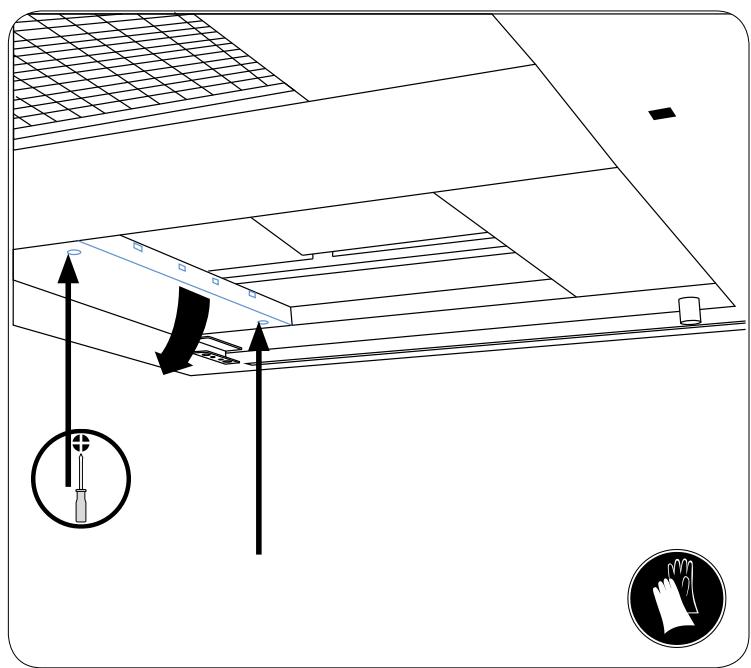
natural_image
Diagram of a roof drainage system with airflow path and magnified view (no text or symbols)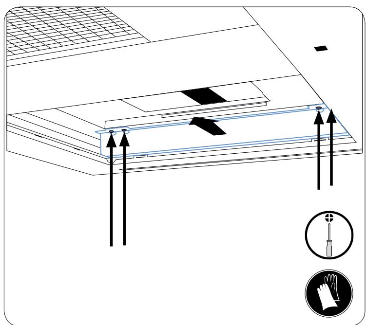
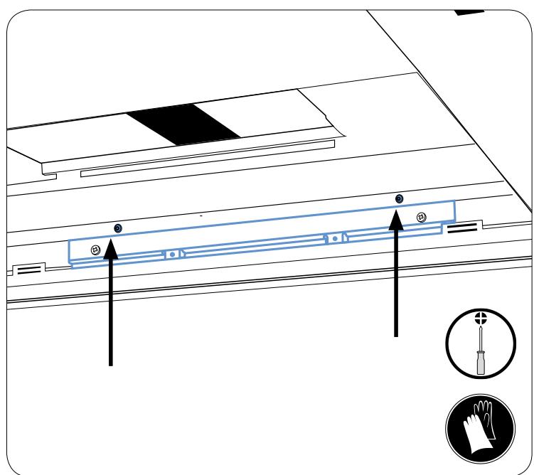
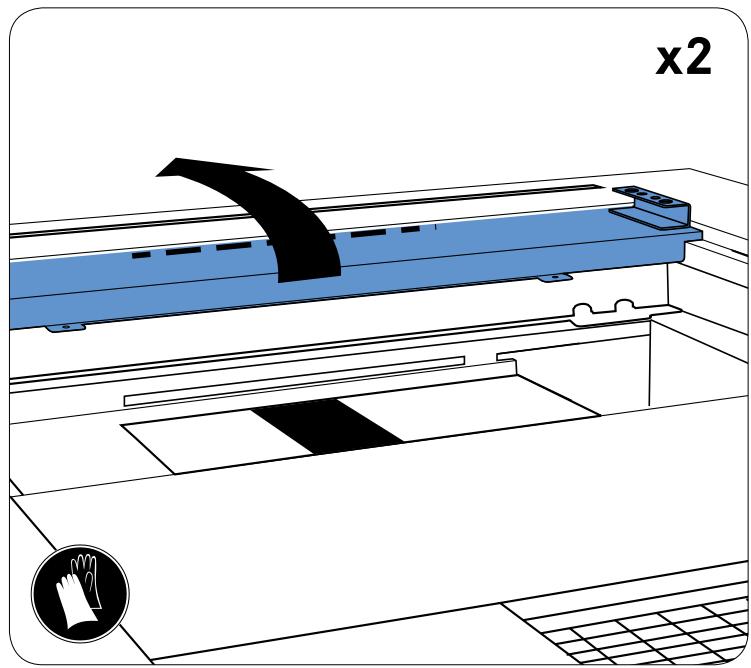
entretien - maintenance - Instandhaltung - manutenzione - mantenimiento - Onderhoud
natural_image
Illustration of hands installing a blue plastic strip on a machine (no text or symbols)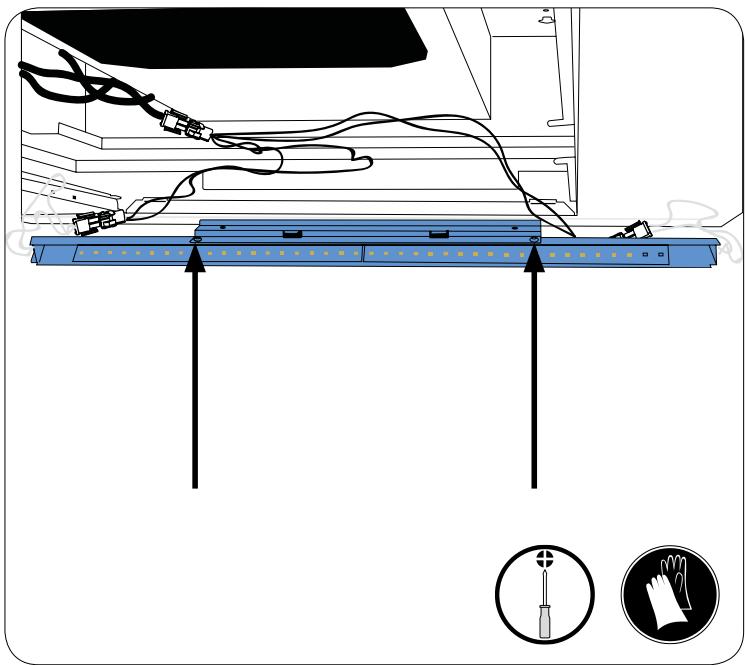
natural_image
Pure diagram of a diagonal line with directional arrows and small vehicle icons, no text or symbols present.Turns on the aspirated engine at the last speed of use. Turns off the engine (and deactivates the delayed shutdown function, if it is active).
-Active engine 10 minutes every hour for 24 hours at a suction speed of 100m3 / h. Hold for 3s: resets to zero the activated filter alarm These signals are only visible when the engine is off.
Turns the lighting on or off at the last intensity used.
Reduces or increases the lighting intensity.
This page explains you how to activate and use the remote control.
-
By default, the remote control supplied with the hood is operational.
-
Otherwise: Press the hood keypad ⏻ for 5 to 6 seconds, the flashing indication ℓ in the display indicates the activation of the telecomande.
- To disable the remote: Press the hood keypad Ⓤ for 5-6 seconds, the tc indication 1 flash in the display.
Please observe the recommendations previously cited in the MAINTENANCE and WARRANTY AND AFTER-SALES SERVICE PARAGRAPHES.
| Step 1 | Step 2 | ||
| Problems | Details and/or conditions of the problems | Checking operations | Action to be taken if «Step 1» has not helped to solve the problem or if it requires an additional maintenance operation. |
| The hood does not work. | No function operates (suction, lighting, etc.). | Check the general electrical distribution board.Check the connection of the power cable to the hood and its connection to the domestic electricity mains. | If you observe a fault in the electricity power supply (1 or 2) call in an electrician.If everything is OK but the problem persists, call in a specialized repairer |
| The hood does not answer to the remote control. | Check that the batteries are correctly positioned in the remote control unit.Check the state of charge of the remote control batteries.The distance between the hood and the remote control is too long or the direction (angle) of the remote control in relation to the hood is not good.The receiver is off. | Reposition the batteries.Change the batteries (2LR03 1.5 volts) in the remote controlChange the position of the remote control.Check the remote control.If everything is OK but the problem persists, call in a specialized repairer. | |
| Noise, vibration or suction problem. | Recirculation version. | Check the condition of your filters (anti-odour).Check the positioning and fitting of the anti-odour filter.Check the condition of your anti-grease filters. | Clean or change the anti-odour filters.Replace the anti-odour filters.Clean your anti-grease filters.If everything is OK but the problem persists, call in a specialized repairer. |
| External ventilating version, low suction despite satisfactory motor speed. | Check the condition of your anti-grease filters.Check the installation of the hood, (fume hood and outlet duct, valve, pipe length, number of elbows and pipe diameter). | Clean your anti-grease filters.If you observe faulty installation or fitting: call in your dealer / installerIf everything is OK but the problem persists, call in a specialized repairer. | |
| Faulty lighting. | Check the condition of the light sources. | Change faulty bulbs.For LEDS call in a specialized repairer. | |
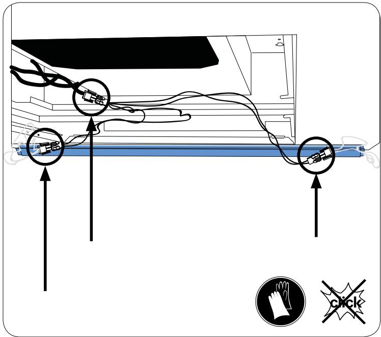
Déconnectez, disconnect, trennen, disconnect, desconectar, losmaken

Utilisez une clé, Use a wrench, Verwenden Sie einen Schraubenschlüssel, Utilizzare una chiave, Utilice una Ilave, Gebruik een sleutel

Équipez vous de gants de protection, Equip your protective gloves, Rüsten Sie Ihre Schutzhandschuhe, Dotare i guanti protettivi, Equipar sus guantes protectores, Rust uw beschermende handschoenen