
LTE7460 - LTE Router ZYXEL - Free user manual and instructions
Find the device manual for free LTE7460 ZYXEL in PDF.

| Product type | LTE router |
| Brand | ZYXEL |
| Model | LTE7460 |
| Dimensions (L x W x H) | Approximately 200 x 200 x 30 mm |
| Weight | Approximately 500 g |
| Power supply | 12 V / 1.5 A power adapter |
| Cellular connectivity | 4G LTE Cat 4, multiple bands |
| Wi-Fi connectivity | Wi-Fi 802.11ac dual-band (2.4 GHz + 5 GHz) |
| Ethernet ports | 4 Gigabit LAN ports, 1 Gigabit WAN port |
| Wireless security | WPA2-PSK, WPA3 |
| Main functions | LTE connection sharing, firewall, VPN, QoS |
| Antennas | 2 external removable antennas for LTE |
| Maintenance and cleaning | Clean with a dry, non-abrasive cloth |
| Spare parts | Antennas, power adapter available as options |
| Repairability | Repairability index: 7/10 |
| General information | Class B digital device, compliant with NMB-003 standard |
Frequently Asked Questions - LTE7460 ZYXEL
User questions about LTE7460 ZYXEL
0 question about this device. Answer the ones you know or ask your own.
Ask a new question about this device
Download the instructions for your LTE Router in PDF format for free! Find your manual LTE7460 - ZYXEL and take your electronic device back in hand. On this page are published all the documents necessary for the use of your device. LTE7460 by ZYXEL.
USER MANUAL LTE7460 ZYXEL
G.SHDSL.bis Bonded Broadband Gateway
User's Guide
Default Login Details
IP Address http://192.168.1.1
Admin 1234
Password
User user
Password
Firmware Version 3.70
Edition 1, 03/2010
www.zyxel.com
ZyXEL
About This User's Guide
Intended Audience
This manual is intended for people who want to configure the P-793H v2 using the web configurator.
Tips for Reading User's Guides On-Screen
When reading a ZyXEL User's Guide On-Screen, keep the following in mind:
-
If you don't already have the latest version of Adobe Reader, you can download it from http://www.adobe.com.
-
Use the PDF's bookmarks to quickly navigate to the areas that interest you. Adobe Reader's bookmarks pane opens by default in all ZyXEL User's Guide PDFs.
-
If you know the page number or know vaguely which page-range you want to view, you can enter a number in the toolbar in Reader, then press [ENTER] to jump directly to that page.
-
Type [CTRL] + [F] to open the Adobe Reader search utility and enter a word or phrase. This can help you quickly pinpoint the information you require. You can also enter text directly into the toolbar in Reader.
-
To quickly move around within a page, press the [SPACE] bar. This turns your cursor into a "hand" with which you can grab the page and move it around freely on your screen.
-
Embedded hyperlinks are actually cross-references to related text. Click them to jump to the corresponding section of the User's Guide PDF.
Related Documentation
- Quick Start Guide
The Quick Start Guide is designed to help you get up and running right away. It contains information on setting up your network and configuring for Internet access.
- Support Disc
Refer to the included CD for support documents.
Documentation Feedback
Send your comments, questions or suggestions to: techwriters@zyxel.com.tw
Thank you!
The Technical Writing Team, ZyXEL Communications Corp.,
6 Innovation Road II, Science-Based Industrial Park, Hsinchu, 30099, Taiwan.
Need More Help?
More help is available at www.zyxel.com.
- Download Library
Search for the latest product updates and documentation from this link. Read the Tech Doc Overview to find out how to efficiently use the User Guide, Quick Start Guide and Command Line Interface Reference Guide in order to better understand how to use your product.
Knowledge Base
If you have a specific question about your product, the answer may be here. This is a collection of answers to previously asked questions about ZyXEL products.
- Forum
This contains discussions on ZyXEL products. Learn from others who use ZyXEL products and share your experiences as well.
Customer Support
Should problems arise that cannot be solved by the methods listed above, you should contact your vendor. If you cannot contact your vendor, then contact a ZyXEL office for the region in which you bought the device.
See http://www.zyxel.com/web/contact_us.php for contact information. Please have the following information ready when you contact an office.
- Product model and serial number.
Warranty Information. - Date that you received your device.
- Brief description of the problem and the steps you took to solve it.
Disclaimer
Graphics in this book may differ slightly from the product due to differences in operating systems, operating system versions, or if you installed updated firmware/software for your device. Every effort has been made to ensure that the information in this manual is accurate.
Document Conventions
Warnings and Notes
These are how warnings and notes are shown in this User's Guide.
Warnings tell you about things that could harm you or your device.
Note: Notes tell you other important information (for example, other things you may need to configure or helpful tips) or recommendations.
Syntax Conventions
- The P-793H v2 may be referred to as the "device", the "system" or the "product" in this User's Guide.
- Product labels, screen names, field labels and field choices are all in bold font.
- A key stroke is denoted by square brackets and uppercase text, for example, [ENTER] means the "enter" or "return" key on your keyboard.
- "Enter" means for you to type one or more characters and then press the [ENTER] key. "Select" or "choose" means for you to use one of the predefined choices.
- A right angle bracket (>) within a screen name denotes a mouse click. For example, Maintenance > Log > Log Setting means you first click Maintenance in the navigation panel, then the Log sub menu and finally the Log Setting tab to get to that screen.
- Units of measurement may denote the "metric" value or the "scientific" value. For example, "k" for kilo may denote "1000" or "1024", "M" for mega may denote "1000000" or "1048576" and so on.
- "e.g.," is a shorthand for "for instance", and "i.e.," means "that is" or "in other words".
Icons Used in Figures
Figures in this User's Guide may use the following generic icons. The P-793H v2 icon is not an exact representation of your device.
| P-793H v2 | Computer | Notebook computer |
| DSL | ||
| Server | Firewall | Telephone |
| Switch | Router |
SafetyWarnings
- Do NOT use this product near water, for example, in a wet basement or near a swimming pool.
- Do NOT expose your device to dampness, dust or corrosive liquids.
- Do NOT store things on the device.
- Do NOT install, use, or service this device during a thunderstorm. There is a remote risk of electric shock from lightning.
- Connect ONLY suitable accessories to the device.
- Do NOT open the device or unit. Opening or removing covers can expose you to dangerous high voltage points or other risks. ONLY qualified service personnel should service or disassemble this device. Please contact your vendor for further information.
- Make sure to connect the cables to the correct ports.
- Place connecting cables carefully so that no one will step on them or stumble over them.
- Always disconnect all cables from this device before servicing or disassembling.
- Use ONLY an appropriate power adaptor or cord for your device.
- Connect the power adaptor or cord to the right supply voltage (for example, 110V AC in North America or 230V AC in Europe).
- Do NOT allow anything to rest on the power adaptor or cord and do NOT place the product where anyone can walk on the power adaptor or cord.
- Do NOT use the device if the power adaptor or cord is damaged as it might cause electrocution.
- If the power adaptor or cord is damaged, remove it from the device and the power source.
- Do NOT attempt to repair the power adaptor or cord. Contact your local vendor to order a new one.
- Do not use the device outside, and make sure all the connections are indoors. There is a remote risk of electric shock from lightning.
- Do NOT obstruct the device ventilation slots, as insufficient airflow may harm your device.
- Use only No. 26 AWG (American Wire Gauge) or larger telecommunication line cord
Your product is marked with this symbol, which is known as the WEEE mark. WEEE stands for Waste Electronics and Electrical Equipment. It means that used electrical and electronic products should not be mixed with general waste. Used electrical and electronic equipment should be treated separately.

Contents Overview
User's Guide 35
Getting To Know Your P-793H v2 37
Introducing the Web Configurator 43
Status Screens 51
Internet Setup Wizard 57
Tutorials 67
Technical Reference 73
WAN Setup 75
LAN Setup 101
Network Address Translation (NAT) 117
Firewalls 133
Content Filtering 155
VPN 161
Certificates 193
Static Route 203
802.1Q/1P 207
Quality of Service (QoS) 217
Dynamic DNS Setup 235
Remote Management 239
Universal Plug-and-Play (UPnP) 251
System Settings 263
Logs 269
Tools 283
Diagnostic 297
Introducing the SMT 301
General Setup 307
WAN Setup 311
LAN Setup 317
Internet Access Setup 321
Remote Node Setup 325
Static Route Setup 335
NAT Setup 339
353
Firewall Setup 355
Filter Configuration 357
System Password 373
System Information & Diagnosis 375
Firmware and Configuration File Maintenance 387
403
Schedule Setup 411
Troubleshooting 415
Table of Contents
About This User's Guide 3
Document Conventions 6
SafetyWarnings 8
Contents Overview 9
Table of Contents 11
List of Figures 23
List of Tables 31
Part I: User's Guide 35
Chapter 1 Getting To Know Your P-793H v2 37
1.1 Overview 37
1.1.1 High-speed Internet Access with G.SHDSL 37
1.1.2 High-speed Point-to-point Connections 38
1.1.3 High-speed Point-to-2points Connections 38
1.2 Ways to Manage the P-793H v2 39
1.3 Good Habits for Managing the P-793H v2 40
1.4 LEDs 40
1.5 The RESET Button 41
1.5.1 Using the RESET Button 41
Chapter 2 Introducing the Web Configurator 43
2.1 Web Configurator Overview 43
2.2 Accessing the Web Configurator 43
2.3 Web Configurator Main Screen 45
2.3.1 Title Bar 46
2.3.2 Navigation Panel 46
2.3.3 Main Window 49
2.3.4 Status Bar 49
Chapter 3 Status Screens 51
3.1 Overview 51
3.2 The Status Screen 51
3.3 Client List 54
3.4 Status: VPN Status 54
3.5 Any IP Table 54
3.6 Packet Statistics 55
Chapter 4
Internet Setup Wizard 57
4.1 Overview 57
4.2 Internet Access Wizard Setup 57
4.2.1 Manual Configuration 60
Chapter 5
Tutorials 67
5.1 Overview 67
5.2 Configuring Point-to-point Connection 67
5.2.1 Set Up the Server 68
5.2.2 Set Up the Client 69
5.2.3 Connect the P-793H v2s 69
5.3 Configuring a Point-to-2points Connection 70
5.3.1 Set up the Server 70
5.3.2 Set up the Clients 71
5.3.3 Connect the P-793H v2s 72
Part II: Technical Reference 73
Chapter 6
WAN Setup. 75
6.1 Overview 75
6.1.1 What You Can Do in the WAN Screens 75
6.1.2 What You Need to Know About WAN 76
6.1.3 Before You Begin 77
6.2 The Internet Access Setup Screen 78
6.2.1 2Wire-2Line Service Mode 82
6.2.2 Advanced Internet Access Setup 83
6.3 The More Connections Screen 86
6.3.1 More Connections Edit 87
6.3.2 Configuring More Connections Advanced Setup 90
6.4 The WAN Backup Setup Screen 92
6.5 WAN Technical Reference 93
6.5.1 Encapsulation 93
6.5.2 Multiplexing 95
6.5.3 VPI and VCI 95
6.5.4 IP Address Assignment 95
6.5.5 Nailed-Up Connection (PPP) 96
6.5.6 NAT 96
6.6 Metric 96
6.7 Traffic Redirect 97
6.8 Traffic Shaping 98
6.8.1 ATM Traffic Classes 99
Chapter 7 LAN Setup. 101
7.1 Overview 101
7.1.1 What You Can Do in the LAN Screens 101
7.1.2 What You Need To Know About LAN 102
7.1.3 Before You Begin 103
7.2 The IP Screen 103
7.2.1 The Advanced LAN IP Setup Screen 104
7.3 The DHCP Setup Screen 106
7.4 The Client List Screen 108
7.5 The IP Alias Screen 109
7.5.1 Configuring the LAN IP Alias Screen 110
7.6 LAN Technical Reference 111
7.6.1 LANs, WANs and the ZyXEL Device 111
7.6.2 DHCP Setup 112
7.6.3 DNS Server Addresses 112
7.6.4 LAN TCP/IP 113
7.6.5 RIP Setup 114
7.6.6 Multicast 114
Chapter 8 Network Address Translation (NAT) 117
8.1 Overview 117
8.1.1 What You Can Do in the NAT Screens 117
8.1.2 What You Need To Know About NAT 117
8.2 The NAT General Setup Screen 119
8.3 The Port Forwarding Screen 120
8.3.1 Configuring the Port Forwarding Screen 121
8.3.2 The Port Forwarding Rule Edit Screen 122
8.4 The Address Mapping Screen 123
8.4.1 The Address Mapping Rule Edit Screen 125
8.5 The ALG Screen 127
8.6 NAT Technical Reference 127
8.6.1 NAT Definitions 127
8.6.2 What NAT Does 128
8.6.3 How NAT Works 129
8.6.4 NAT Application 130
8.6.5 NAT Mapping Types 130
Chapter 9
Firewalls 133
9.1 Overview 133
9.1.1 What You Can Do in the Firewall Screens 133
9.1.2 What You Need to Know About Firewall 134
9.1.3 Firewall Rule Setup Example 135
9.2 The Firewall General Screen 138
9.3 The Firewall Rule Screen 140
9.3.1 Configuring Firewall Rules 142
9.3.2 Customized Services 144
9.3.3 Configuring a Customized Service 145
9.4 The Firewall Threshold Screen 145
9.4.1 Threshold Values 146
9.4.2 Configuring Firewall Thresholds 147
9.5 Firewall Technical Reference 149
9.5.1 Firewall Rules Overview 149
9.5.2 Guidelines For Enhancing Security With Your Firewall 150
9.5.3 Security Considerations 151
9.5.4 Triangle Route 151
Chapter 10
Content Filtering 155
10.1 Overview 155
10.1.1 What You Can Do in the Content Filter Screens 155
10.1.2 What You Need to Know About Content Filtering 155
10.1.3 Before You Begin 155
10.1.4 Content Filtering Example 156
10.2 The Keyword Screen 158
10.3 The Schedule Screen 159
10.4 The Trusted Screen 160
Chapter 11
VPN 161
11.1 Overview 161
11.1.1 What You Can Do in the VPN Screens 161
11.1.2 What You Need to Know About IPSec VPN 162
11.1.3 Before You Begin 163
11.2 VPN Setup Screen 163
11.3 The VPN Edit Screen 166
11.4 Configuring Advanced IKE Settings 171
11.5 Manual Key Setup 173
11.5.1 Security Parameter Index (SPI) 174
11.6 Configuring Manual Key 174
11.7 Viewing SA Monitor 177
11.8 Configuring VPN Global Setting 179
11.9 IPSec VPN Technical Reference 179
11.9.1 IPSec Architecture 180
11.9.2 IPSec and NAT 180
11.9.3 VPN, NAT, and NAT Traversal 181
11.9.4 Encapsulation 183
11.9.5 IKE Phases 184
11.9.6 Negotiation Mode 185
11.9.7 Keep Alive 185
11.9.8 Remote DNS Server 185
11.9.9 ID Type and Content 186
11.9.10 Pre-Shared Key 188
11.9.11 Diffie-Hellman (DH) Key Groups 188
11.9.12 Telecommuter VPN/IPSec Examples 188
Chapter 12
Certificates 193
12.1 Overview 193
12.1.1 What You Need to Know About Certificates 193
12.1.2 Verifying a Certificate 194
12.2 The Trusted CAs Screen 195
12.2.1 Trusted CA Import 197
12.2.2 Trusted CA Details 198
12.3 Certificates Technical Reference 200
12.3.1 Certificates Overview 200
12.3.2 Private-Public Certificates 200
Chapter 13
Static Route 203
13.1 Overview 203
13.2 The Static Route Screen 204
13.2.1 Static Route Edit 205
Chapter 14
802.1Q/1P 207
14.1 Overview 207
14.1.1 What You Can Do in the 802.1Q/1P Screens 207
14.1.2 What You Need to Know About 802.1Q/1P 207
14.1.3 802.1Q/1P Example 209
14.2 The 802.1Q/1P Group Setting Screen 213
14.2.1 Editing 802.1Q/1P Group Setting 214
14.3 The 802.1Q/1P Port Setting Screen 215
Chapter 15
Quality of Service (QoS) 217
15.1 Overview 217
15.2 QoS Overview 217
15.2.1 What You Can Do in the QoS Screens 218
15.2.2 What You Need to Know About QoS 218
15.2.3 QoS Class Setup Example 219
15.3 The QoS General Screen 223
15.4 The Class Setup Screen 224
15.4.1 The Class Configuration Screen 226
15.5 The QoS Monitor Screen 230
15.6 QoS Technical Reference 231
15.6.1 IEEE 802.1Q Tag 231
15.6.2 IP Precedence 231
15.6.3 DiffServ 232
15.6.4 Automatic Priority Queue Assignment 232
Chapter 16
Dynamic DNS Setup 235
16.1 Overview 235
16.1.1 What You Need To Know About DDNS 235
16.2 The Dynamic DNS Screen 236
Chapter 17
Remote Management 239
17.1 Overview 239
17.1.1 What You Can Do in the Remote Management Screens 240
17.1.2 What You Need to Know About Remote Management 240
17.2 The WWW Screen 241
17.2.1 Configuring the WWW Screen 241
17.3 The Telnet Screen 242
17.4 The FTP Screen 243
17.5 The SNMP Screen 244
17.5.1 Supported MIBs 246
17.5.2 SNMP Traps 246
17.5.3 Configuring SNMP 247
17.6 The DNS Screen 248
17.7 The ICMP Screen 249
Chapter 18
Universal Plug-and-Play (UPnP) 251
18.1 Overview 251
18.1.1 What You Can Do in the UPnP Screen 251
18.1.2 What You Need to Know About UPnP 251
18.2 The UPnP Screen 253
18.3 Installing UPnP in Windows Example 253
18.4 Using UPnP in Windows XP Example 257
Chapter 19
System Settings 263
19.1 Overview 263
19.1.1 What You Can Do in the System Settings Screens 263
19.1.2 What You Need to Know About System Settings 263
19.2 The General Screen 264
19.3 The Time Setting Screen 266
Chapter 20
Logs 269
20.1 Overview 269
20.1.1 What You Can Do in the Log Screens 269
20.1.2 What You Need To Know About Logs 269
20.2 The View Log Screen 270
20.3 The Log Settings Screen 271
20.4 SMTP Error Messages 273
20.4.1 Example E-mail Log 273
20.5 Log Descriptions 274
Chapter 21
Tools 283
21.1 Overview 283
21.1.1 What You Can Do in the Tool Screens 283
21.1.2 What You Need To Know About Tools 284
21.1.3 Before You Begin 285
21.1.4 Tool Examples 285
21.2 The Firmware Screen 291
21.3 The Configuration Screen 293
21.4 The Restart Screen 295
Chapter 22
Diagnostic 297
22.1 Overview 297
22.1.1 What You Can Do in the Diagnostic Screens 297
22.2 The General Diagnostic Screen 297
22.3 The DSL Line Diagnostic Screen 298
Chapter 23
Introducing the SMT 301
23.1 Accessing the SMT 301
23.2 SMT Menu Items 302
23.3 Navigating the SMT Interface 305
Chapter 24
General Setup 307
24.1 Configuring General Setup 307
24.1.1 Configuring Dynamic DNS 308
Chapter 25
WAN Setup 311
25.1 WAN Setup 311
25.1.1 2wire-2line Service Mode 313
25.2 Configuring Traffic Redirect 315
Chapter 26
LAN Setup 317
26.1 Accessing the LAN Menus 317
26.2 LAN Port Filter Setup 317
26.3 TCP/IP and DHCP Setup Menu 318
26.4 LAN IP Alias 320
Chapter 27
Internet Access Setup 321
27.1 Internet Access Setup 321
Chapter 28
Remote Node Setup 325
28.1 Introduction to Remote Node Setup 325
28.2 Remote Node Setup 325
28.3 Remote Node Profile 326
28.4 Remote Node Network Layer Options 328
28.5 Remote Node Filter 330
28.6 Remote Node ATM Layer Options 332
28.7 Advance Setup Options 333
Chapter 29
Static Route Setup 335
29.1 IP Static Route Setup 335
29.2 Bridge Static Route Setup 337
Chapter 30
NAT Setup 339
30.1 Using NAT 339
30.1.1 SUA (Single User Account) Versus NAT 339
30.1.2 Applying NAT 340
30.2 NAT Setup 341
30.2.1 Address Mapping Sets 342
30.3 Configuring a Server behind NAT 345
30.4 General NAT Examples 346
30.4.1 Internet Access Only 347
30.4.2 Example 2: Internet Access with a Default Server 348
30.4.3 Example 3: Multiple Public IP Addresses With Inside Servers 348
30.4.4 Example 4: NAT Unfriendly Application Programs 352
Chapter 31
Firewall Setup 355
31.1 Using P-793H v2 SMT Menus 355
31.1.1 Activating the Firewall 355
Chapter 32
Filter Configuration 357
32.1 Introduction to Filters 357
32.1.1 The Filter Structure of the P-793H v2 358
32.2 Configuring a Filter Set 360
32.2.1 Configuring a Filter Rule 362
32.2.2 Configuring a TCP/IP Filter Rule 362
32.2.3 Configuring a Generic Filter Rule 366
32.3 Example Filter 367
32.4 Filter Types and NAT 369
32.5 Firewall Versus Filters 370
32.6 Applying a Filter 370
32.6.1 Applying LAN Filters 370
32.6.2 Applying Remote Node Filters 371
Chapter 33
System Password 373
Chapter 34
System Information & Diagnosis 375
34.1 Introduction to System Status 375
34.2 System Status 375
34.3 System Information and Console Port Speed 377
34.3.1 System Information 378
34.3.2 Console Port Speed 379
34.4 Log and Trace 379
34.4.1 Viewing Error Log 379
34.4.2 Syslog Logging 381
34.5 Diagnostic 384
Chapter 35
Firmware and Configuration File Maintenance 387
35.1 Introduction 387
35.2 Filename Conventions 387
35.3 Backup Configuration 388
35.3.1 Backup Configuration 389
35.3.2 Using the FTP Command from the Command Line 389
35.3.3 Example of FTP Commands from the Command Line 390
35.3.4 GUI-based FTP Clients 390
35.3.5 File Maintenance Over WAN 390
35.3.6 Backup Configuration Using TFTP 391
35.3.7 TFTP Command Example 391
35.3.8 GUI-basedTFTPClients 392
35.3.9 Backup Via Console Port 392
35.4 Restore Configuration 393
35.4.1 Restore Using FTP 394
35.4.2 Restore Using FTP Session Example 395
35.4.3 Restore Via Console Port 395
35.5 Uploading Firmware and Configuration Files 396
35.5.1 Firmware File Upload 396
35.5.2 Configuration File Upload 397
35.5.3 FTP File Upload Command from the DOS Prompt Example 398
35.5.4 FTP Session Example of Firmware File Upload 398
35.5.5 TFTP File Upload 399
35.5.6 TFTP Upload Command Example 399
35.5.7 Uploading Via Console Port 400
35.5.8 Uploading Firmware File Via Console Port 400
35.5.9 Example Xmodem Firmware Upload Using HyperTerminal 401
35.5.10 Uploading Configuration File Via Console Port 401
35.5.11 Example Xmodem Configuration Upload Using HyperTerminal 402
Chapter 36
403
36.1 Command Interpreter Mode 403
36.1.1 Command Syntax 403
36.1.2 Command Usage 404
36.2 Call Control Support 404
36.2.1 Budget Management 405
36.3 Time and Date Setting 406
36.4 Remote Management 409
36.4.1 Remote Management Limitations 409
Chapter 37
Schedule Setup 411
37.1 Schedule Set Overview 411
37.2 Schedule Setup 411
37.3 Schedule Set Setup 412
Chapter 38
Troubleshooting 415
38.1 Power, Hardware Connections, and LEDs 415
38.2 P-793H v2 Access and Login 416
38.3 Internet Access 418
38.4 Network Connections 419
Appendix A Product Specifications 421
Appendix B Wall-mounting Instructions 427
Appendix C Setting up Your Computer's IP Address 429
Appendix D Pop-up Windows, JavaScripts and Java Permissions 453
Appendix E IP Addresses and Subnetting 463
Appendix F Services 473
Appendix G Legal Information 477
Index 481
List of Figures
Figure 1 High-speed Internet Access with Your P-793H v2 38
Figure 2 Point-to-point Connections with Your P-793H v2 38
Figure 3 Point-to-2points Connections with Your P-793H v2 39
Figure 4 LEDs 40
Figure 5 Login Screen 44
Figure 6 Change Password at Login 44
Figure 7 Select a Mode 45
Figure 8 Main Screen 45
Figure 9 Status Screen 51
Figure 10 Any IP Table 54
Figure 11 Packet Statistics 55
Figure 12 Select a Mode 57
Figure 13 Wizard Welcome 58
Figure 14 Auto Detection: No DSL Connection 58
Figure 15 Auto-Detection: PPPoE 59
Figure 16 Auto Detection: Failed 59
Figure 17 Internet Access Wizard Setup: ISP Parameters 60
Figure 18 Internet Connection with PPPoE 61
Figure 19 Internet Connection with RFC 1483 62
Figure 20 Internet Connection with ENET ENCAP 63
Figure 21 Internet Connection with PPPoA 64
Figure 22 Internet Access Setup Complete 65
Figure 23 WAN > Internet Access Setup 68
Figure 24 WAN > Internet Access Setup 71
Figure 25 WAN > Internet Connection > Service Type of B 72
Figure 26 WAN > Internet Connection > Service Type of C 72
Figure 27 LAN and WAN 75
Figure 28 Network > WAN >Internet Access Setup 78
Figure 29 2wire-2line Service Mode 82
Figure 30 Network > WAN > Internet Access Setup: Advanced Setup 83
Figure 31 Network > WAN > More Connections 86
Figure 32 Network > WAN > More Connections: Edit 87
Figure 33 Network > WAN > More Connections: Edit: Advanced Setup 90
Figure 34 Network > Internet (WAN) > WAN Backup 92
Figure 35 Traffic Redirect Example 97
Figure 36 Traffic Redirect LAN Setup 98
Figure 37 Example of Traffic Shaping 99
Figure 38 Network > LAN > IP 103
Figure 39 Network > LAN > IP: Advanced Setup 104
Figure 40 Network > LAN > DHCP Setup 106
Figure 41 Network > LAN > Client List 108
Figure 42 Physical Network & Partitioned Logical Networks 109
Figure 43 Network > LAN > IP Alias 110
Figure 44 LAN and WAN IP Addresses 111
Figure 45 Network > NAT > General 119
Figure 46 Multiple Servers Behind NAT Example 121
Figure 47 Network > NAT > Port Forwarding 121
Figure 48 Network > NAT > Port Forwarding: Edit 122
Figure 49 Network > NAT > Address Mapping 124
Figure 50 Network > NAT > Address Mapping: Edit 125
Figure 51 Network > NAT > ALG 127
Figure 52 How NAT Works 129
Figure 53 NAT Application With IP Alias 130
Figure 54 Default Firewall Action 133
Figure 55 Security > Firewall > General 138
Figure 56 Security > Firewall > Rules 140
Figure 57 Security > Firewall > Rules: Edit 142
Figure 58 Security > Firewall > Rules: Edit: Edit Customized Services 144
Figure 59 Security > Firewall > Rules: Edit: Edit Customized Services: Config 145
Figure 60 Three-Way Handshake 146
Figure 61 Security > Firewall > Threshold 147
Figure 62 Ideal Firewall Setup 151
Figure 63 "Triangle Route" Problem 152
Figure 64 IP Alias 153
Figure 65 Security > Content Filtering > Keyword 158
Figure 66 Security > Content Filter > Schedule 159
Figure 67 Security > Content Filter: Trusted 160
Figure 68 VPN: Example 161
Figure 69 VPN: IKE SA and IPSec SA 162
Figure 70 IPSec Summary Fields 163
Figure 71 Security > VPN > Setup 164
Figure 72 Security > VPN > Setup > Edit 166
Figure 73 Security > VPN > Setup > Edit > Advanced Setup 171
Figure 74 Security > VPN > Setup > Manual Key 174
Figure 75 Security > VPN > Monitor 178
Figure 76 Security > VPN > Global Setting 179
Figure 77 IPSec Architecture 180
Figure 78 NAT Router Between IPSec Routers 182
Figure 79 Transport and Tunnel Mode IPSec Encapsulation 183
Figure 80 Two Phases to Set Up the IPSec SA 184
Figure 81 VPN Host using Intranet DNS Server Example 186
Figure 82 Telecommuters Sharing One VPN Rule Example 189
Figure 83 Telecommuters Using Unique VPN Rules Example 190
Figure 84 Certificates Example 193
Figure 85 Remote Host Certificates 194
Figure 86 Certificate Details 195
Figure 87 Trusted CAs 196
Figure 88 Trusted CA Import 197
Figure 89 Trusted CA Details 198
Figure 90 Example of Static Routing Topology 203
Figure 91 Advanced > Static Route 204
Figure 92 Advanced > Static Route: Edit 205
Figure 93 802.1Q/1P 207
Figure 94 Advanced > 802.1Q/1P > Group Setting 213
Figure 95 Advanced > 802.1Q/1P > Group Setting > Edit 214
Figure 96 Advanced > 802.1Q/1P > Port Setting 215
Figure 97 QoS Example 220
Figure 98 QoS Class Example: VoIP -1 220
Figure 99 QoS Class Example: VoIP -2 221
Figure 100 QoS Class Example: Boss -1 221
Figure 101 QoS Class Example: Boss -2 222
Figure 102 Advanced > QoS > General 223
Figure 103 Advanced > QoS > Class Setup 224
Figure 104 Advanced > QoS > Class Setup: Edit 226
Figure 105 Advanced > QoS > Monitor 230
Figure 106 Advanced > Dynamic DNS 236
Figure 107 Remote Management From the WAN 239
Figure 108 Advanced > Remote Management > WWW 241
Figure 109 Advanced > Remote Management > Telnet 242
Figure 110 Advanced > Remote Management > FTP 243
Figure 111 SNMP Management Model 245
Figure 112 Advanced > Remote Management > SNMP 247
Figure 113 Advanced > Remote Management > DNS 248
Figure 114 Advanced > Remote Management > ICMP 249
Figure 115 Advanced > UPnP > General 253
Figure 116 Maintenance > System > General 264
Figure 117 Maintenance > System > Time Setting 266
Figure 118 Maintenance > Logs > View Log 270
Figure 119 Maintenance > Logs > Log Settings 271
Figure 120 E-mail Log Example 274
Figure 121 Restore Using FTP Session Example 286
Figure 122 FTP Session Example of Firmware File Upload 287
Figure 123 FTP Session Example 289
Figure 124 Maintenance > Tools > Firmware 291
Figure 125 Firmware Upload In Progress 292
Figure 126 Network Temporarily Disconnected 292
Figure 127 Error Message 292
Figure 128 Maintenance > Tools > Configuration 293
Figure 129 Configuration Upload Successful 294
Figure 130 Network Temporarily Disconnected 294
Figure 131 Configuration Upload Error 294
Figure 132 Reset Warning Message 295
Figure 133 Reset In Process Message 295
Figure 134 Maintenance > Tools > Restart 295
Figure 135 Maintenance > Diagnostic > General 297
Figure 136 Maintenance > Diagnostic > DSL Line 298
Figure 137 Login Screen 301
Figure 138 SMT Main Menu 302
Figure 139 Menu 1: General Setup 307
Figure 140 Menu 1.1: Configure Dynamic DNS 309
Figure 141 Menu 2: WAN Setup 311
Figure 142 Menu 2: 2wire-2line Service Mode 313
Figure 143 Menu 2.1: Traffic Redirect Setup 315
Figure 144 Menu 3: LAN Setup 317
Figure 145 Menu 3.1: LAN Port Filter Setup 317
Figure 146 Menu 3.2: TCP/IP and DHCP Ethernet Setup 318
Figure 147 Menu 3.2.1: IP Alias Setup 320
Figure 148 Menu 4: Internet Access Setup 321
Figure 149 Menu 11: Remote Node Setup 325
Figure 150 Menu 11.1: Remote Node Profile (nodes 1-7) 326
Figure 151 Menu 11.3: Remote Node Network Layer Options 328
Figure 152 Menu 11.5: Remote Node Filter 331
Figure 153 . Menu 11.6: Remote Node ATM Layer Options 332
Figure 154 Menu 11.8: Advance Setup Options 333
Figure 155 Menu 12.1: IP Static Route Setup 335
Figure 156 Menu 12.1.1: Edit IP Static Route 336
Figure 157 Menu 12.3: Bridge Static Route Setup 337
Figure 158 Menu 12.3.1: Edit Bridge Static Route 337
Figure 159 Menu 4: Applying NAT for Internet Access 340
Figure 160 Menu 11.3: Applying NAT to the Remote Node 341
Figure 161 Menu 15: NAT Setup 342
Figure 162 Menu 15.1: Address Mapping Sets 342
Figure 163 Menu 15.1.1: Address Mapping Rules 343
Figure 164 Menu 15.1.1.1: Address Mapping Rule 344
Figure 165 Menu 15.2: NAT Server Sets 345
Figure 166 Menu 15.2: NAT Server Setup 346
Figure 167 NAT Example 1 347
Figure 168 Menu 4: Internet Access & NAT Example 347
Figure 169 NAT Example 2 348
Figure 170 Menu 15.2: Specifying an Inside Server 348
Figure 171 NAT Example 3 349
Figure 172 Example 3: Menu 11.3 350
Figure 173 Example 3: Menu 15.1.1.1 351
Figure 174 Example 3: Final Menu 15.1.1 351
Figure 175 Example 3: Menu 15.2 352
Figure 176 NAT Example 4 352
Figure 177 Example 4: Menu 15.1.1.1: Address Mapping Rule 353
Figure 178 Menu 21: Filter and Firewall Setup 355
Figure 179 Menu 21.2: Firewall Setup 356
Figure 180 Outgoing Packet Filtering Process 357
Figure 181 Filter Rule Process 359
Figure 182 Menu 21: Filter and Firewall Setup 360
Figure 183 Menu 21.1: Filter Set Configuration 360
Figure 184 Menu 21.1.1: Filter Rules Summary 361
Figure 185 Menu 21.1.1.1: TCP/IP Filter Rule 363
Figure 186 Executing an IP Filter 365
Figure 187 Menu 21.1.1.1: Generic Filter Rule 366
Figure 188 Telnet Filter Example 367
Figure 189 Example Filter: Menu 21.1.3.1 368
Figure 190 Example Filter Rules Summary: Menu 21.1.3 369
Figure 191 Protocol and Device Filter Sets 370
Figure 192 Filtering LAN Traffic 371
Figure 193 Filtering Remote Node Traffic 371
Figure 194 Menu 23: System Password 373
Figure 195 Menu 24: System Maintenance 375
Figure 196 Menu 24.1: System Maintenance - Status 376
Figure 197 Menu 24.2: System Information and Console Port Speed 378
Figure 198 Menu 24.2.1: System Maintenance - Information 378
Figure 199 Menu 24.2.2: System Maintenance: Change Console Port Speed 379
Figure 200 Menu 24.3: System Maintenance - Log and Trace 380
Figure 201 Examples of Error and Information Messages 380
Figure 202 Menu 24.3.2: System Maintenance - UNIX Syslog 381
Figure 203 Menu 24.4: System Maintenance - Diagnostic 385
Figure 204 Menu 24.5: Backup Configuration 389
Figure 205 FTP Session Example 390
Figure 206 System Maintenance: Backup Configuration 392
Figure 207 System Maintenance: Starting Xmodem Download Screen 393
Figure 208 Backup Configuration Example 393
Figure 209 Successful Backup Confirmation Screen 393
Figure 210 Menu 24.6:Restore Configuration 394
Figure 211 Restore Using FTP Session Example 395
Figure 212 System Maintenance:Restore Configuration 395
Figure 213 System Maintenance: Starting Xmodem Download Screen 395
Figure 214 Restore Configuration Example 396
Figure 215 Successful Restoration Confirmation Screen 396
Figure 216 Menu 24.7.1: System Maintenance - Upload System Firmware 397
Figure 217 Menu 24.7.2: System Maintenance - Upload System Configuration File 397
Figure 218 FTP Session Example of Firmware File Upload 398
Figure 219 Menu 24.7.1 As Seen Using the Console Port 400
Figure 220 Example Xmodem Upload 401
Figure 221 Menu 24.7.2 As Seen Using the Console Port 401
Figure 222 Example Xmodem Upload 402
Figure 223 Command Mode in Menu 24 403
Figure 224 Valid Commands 404
Figure 225 Menu 24.9: System Maintenance - Call Control 405
Figure 226 Menu 24.9.1 - Budget Management 405
Figure 227 Menu 24: System Maintenance 406
Figure 228 Menu 24.10: System Maintenance - Time and Date Setting 407
Figure 229 Menu 24.11 - Remote Management Control 409
Figure 230 Menu 26: Schedule Setup 411
Figure 231 Menu 26.1: Schedule Set Setup 412
Figure 232 Y-Cable Configuration 426
Figure 233 Wall-mounting Example 427
Figure 234 Windows 95/98/Me: Network: Configuration 430
Figure 235 Windows 95/98/Me: TCP/IP Properties: IP Address 431
Figure 236 Windows 95/98/Me: TCP/IP Properties: DNS Configuration 432
Figure 237 Windows XP: Start Menu 433
Figure 238 Windows XP: Control Panel 433
Figure 239 Windows XP: Control Panel: Network Connections: Properties 434
Figure 240 Windows XP: Local Area Connection Properties 434
Figure 241 Windows XP: Internet Protocol (TCP/IP) Properties 435
Figure 242 Windows XP: Advanced TCP/IP Properties 436
Figure 243 Windows XP: Internet Protocol (TCP/IP) Properties 437
Figure 244 Windows Vista: Start Menu 438
Figure 245 Windows Vista: Control Panel 438
Figure 246 Windows Vista: Network And Internet 438
Figure 247 Windows Vista: Network and Sharing Center 439
Figure 248 Windows Vista: Network and Sharing Center 439
Figure 249 Windows Vista: Local Area Connection Properties 440
Figure 250 Windows Vista: Internet Protocol Version 4 (TCP/IPv4) Properties 441
Figure 251 Windows Vista: Advanced TCP/IP Properties 442
Figure 252 Windows Vista: Internet Protocol Version 4 (TCP/IPv4) Properties 443
Figure 253 Macintosh OS 8/9: Apple Menu 444
Figure 254 Macintosh OS 8/9: TCP/IP 445
Figure 255 Macintosh OS X: Apple Menu 446
Figure 256 Macintosh OS X: Network 446
Figure 257 Red Hat 9.0: KDE: Network Configuration: Devices 447
Figure 258 Red Hat 9.0: KDE: Ethernet Device: General 448
Figure 259 Red Hat 9.0: KDE: Network Configuration: DNS 448
Figure 260 Red Hat 9.0: KDE: Network Configuration: Activate 449
Figure 261 Red Hat 9.0: Dynamic IP Address Setting in ifconfig-eth0 449
Figure 262 Red Hat 9.0: Static IP Address Setting in ifconfig-eth0 450
Figure 263 Red Hat 9.0: DNS Settings in resolv.conf 450
Figure 264 Red Hat 9.0: Restart Ethernet Card 450
Figure 265 Red Hat 9.0: Checking TCP/IP Properties 451
Figure 266 Pop-up Blocker 453
Figure 267 Internet Options: Privacy 454
Figure 268 Internet Options: Privacy 455
Figure 269 Pop-up Blocker Settings 456
Figure 270 Internet Options: Security 457
Figure 271 Security Settings - Java Scripting 458
Figure 272 Security Settings - Java 459
Figure 273 Java (Sun) 460
Figure 274 Mozilla Firefox: Tools > Options 460
Figure 275 Mozilla Firefox Content Security 461
Figure 276 Network Number and Host ID 464
Figure 277 Subnetting Example: Before Subnetting 467
Figure 278 Subnetting Example: After Subnetting 467
List of Tables
Table 1 LEDs 40
Table 2 Web Configurator Icons in the Title Bar 46
Table 3 Navigation Panel Summary 46
Table 4 Status Screen 52
Table 5 Any IP Table 54
Table 6 Packet Statistics 55
Table 7 Internet Access Wizard Setup: ISP Parameters 60
Table 8 Internet Connection with PPPoE 62
Table 9 Internet Connection with RFC 1483 63
Table 10 Internet Connection with ENET ENCAP 64
Table 11 Internet Connection with PPPoA 65
Table 12 Network > WAN > Internet Access Setup 79
Table 13 2wire-2line Service Mode 82
Table 14 Network > WAN > Internet Access Setup: Advanced Setup 83
Table 15 Network > WAN > More Connections 86
Table 16 Network > WAN > More Connections: Edit 87
Table 17 Network > WAN > More Connections: Edit: Advanced Setup 90
Table 18 Network > Internet (WAN) > WAN Backup 92
Table 19 Network > LAN > IP 104
Table 20 Network > LAN > IP: Advanced Setup 105
Table 21 Network > LAN > DHCP Setup 107
Table 22 Network > LAN > Client List 108
Table 23 Network > LAN > IP Alias 110
Table 24 Network > NAT > General 119
Table 25 Network > NAT > Port Forwarding 122
Table 26 Network > NAT > Port Forwarding: Edit 123
Table 27 Network > NAT > Address Mapping 124
Table 28 Network > NAT > Address Mapping: Edit 126
Table 29 Network > NAT > ALG 127
Table 30 NAT Definitions 128
Table 31 NAT Mapping Types 131
Table 32 Security > Firewall > General 139
Table 33 Security > Firewall > Rules 140
Table 34 Security > Firewall > Rules: Edit 142
Table 35 Security > Firewall > Rules: Edit: Edit Customized Services 144
Table 36 Security > Firewall > Rules: Edit: Edit Customized Services: Config 145
Table 37 Security > Firewall > Threshold 147
Table 38 Security > Content Filtering > Keyword 158
Table 39 Security > Content Filter: Schedule 159
Table 40 Security > Content Filter: Trusted 160
Table 41 Security > VPN > Setup 164
Table 42 Security > VPN > Setup > Edit 166
Table 43 Security > VPN > Setup > Edit > Advanced Setup 171
Table 44 Security > VPN > Setup > Manual Key 175
Table 45 Security > VPN > Monitor 178
Table 46 Security > VPN > Global Setting 179
Table 47 VPN and NAT 181
Table 48 VPN and NAT 182
Table 49 Local ID Type and Content Fields 187
Table 50 Peer ID Type and Content Fields 187
Table 51 Matching ID Type and Content Configuration Example 188
Table 52 Mismatching ID Type and Content Configuration Example 188
Table 53 Telecommuters Sharing One VPN Rule Example 189
Table 54 Telecommuters Using Unique VPN Rules Example 190
Table 55 Trusted CAs 196
Table 56 Trusted CA Import 197
Table 57 Trusted CA Details 198
Table 58 Advanced > Static Route 204
Table 59 Advanced > Static Route: Edit 205
Table 60 Advanced > 802.1Q/1P > Group Setting 213
Table 61 Advanced > 802.1Q/1P > Group Setting > Edit 214
Table 62 Advanced > 802.1Q/1P > Port Setting 216
Table 63 Advanced > QoS > General 223
Table 64 Advanced > QoS > Class Setup 224
Table 65 Advanced > QoS > Class Setup: Edit 227
Table 66 Advanced > QoS > Monitor 230
Table 67 IEEE 802.1p Priority Level and Traffic Type 231
Table 68 Internal Layer2 and Layer3 QoS Mapping 233
Table 69 Advanced > Dynamic DNS 236
Table 70 Advanced > Remote Management > WWW 242
Table 71 Advanced > Remote Management > Telnet 243
Table 72 Advanced > Remote Management > FTP 244
Table 73 SNMP Traps 246
Table 74 Advanced > Remote Management > SNMP 247
Table 75 Advanced > Remote Management > DNS 248
Table 76 Advanced > Remote Management > ICMP 249
Table 77 Advanced > UPnP > General 253
Table 78 Maintenance > System > General 265
Table 79 Maintenance > System > Time Setting 266
Table 80 Maintenance > Logs > View Log 270
Table 81 Maintenance > Logs > Log Settings 272
Table 82 SMTP Error Messages 273
Table 83 System Maintenance Logs 274
Table 84 System Error Logs 275
Table 85 Access Control Logs 276
Table 86 TCP Reset Logs 276
Table 87 Packet Filter Logs 277
Table 88 ICMP Logs 277
Table 89 CDR Logs 278
Table 90 PPP Logs 278
Table 91 UPnP Logs 278
Table 92 Content Filtering Logs 278
Table 93 Attack Logs 279
Table 94 802.1X Logs 279
Table 95 ACL Setting Notes 280
Table 96 ICMP Notes 280
Table 97 Syslog Logs 281
Table 98 RFC-2408 ISAKMP Payload Types 282
Table 99 Filename Conventions 284
Table 100 General Commands for GUI-based FTP Clients 289
Table 101 General Commands for GUI-based TFTP Clients 290
Table 102 Maintenance > Tools > Firmware 291
Table 103 Restore Configuration 293
Table 104 Maintenance > Diagnostic > General 298
Table 105 Maintenance > Diagnostic > DSL Line 299
Table 106 Main Menu Summary 302
Table 107 SMT Menus Overview 303
Table 108 Main Menu Commands 305
Table 109 Menu 1: General Setup 307
Table 110 Menu 1.1: Configure Dynamic DNS 309
Table 111 Menu 2: WAN Setup 312
Table 112 Menu 2: 2wire-2line Service Mode 314
Table 113 Menu 2.1: Traffic Redirect Setup 315
Table 114 Menu 3.2: TCP/IP and DHCP Ethernet Setup 318
Table 115 Menu 3.2.1: IP Alias Setup 320
Table 116 Menu 4: Internet Access Setup 321
Table 117 Menu 11.1: Remote Node Profile (nodes 1-7) 326
Table 118 Menu 11.3: Remote Node Network Layer Options 328
Table 119 Menu 11.5: Remote Node Filter 331
Table 120 Menu 11.6: Remote Node ATM Layer Options 332
Table 121 Menu 11.8: Advance Setup Options 333
Table 122 Menu 12.1.1: Edit IP Static Route 336
Table 123 Menu 12.3.1: Edit Bridge Static Route 337
Table 124 Applying NAT in Menus 4 & 11.3 341
Table 125 Menu 15.1.1: Address Mapping Rules 343
Table 126 Menu 15.1.1.1: Address Mapping Rule 344
Table 127 Menu 15.2: NAT Server Setup 346
Table 128 Abbreviations Used in the Filter Rules Summary Menu 361
Table 129 Rule Abbreviations Used 362
Table 130 Menu 21.1.1.1: TCP/IP Filter Rule 363
Table 131 Menu 21.1.1.1: Generic Filter Rule 366
Table 132 Menu 23: System Password 373
Table 133 Menu 24.1: System Maintenance - Status 376
Table 134 Menu 24.2.1: System Maintenance - Information 378
Table 135 Menu 24.3.2: System Maintenance - UNIX Syslog 381
Table 136 Menu 24.4: System Maintenance - Diagnostic 385
Table 137 Filename Conventions 388
Table 138 General Commands for GUI-based FTP Clients 390
Table 139 General Commands for GUI-based TFTP Clients 392
Table 140 Menu 24.9.1 - Budget Management 405
Table 141 Menu 24.10: System Maintenance - Time and Date Setting 407
Table 142 Menu 24.11 - Remote Management Control 409
Table 143 Menu 26: Schedule Setup 412
Table 144 Menu 26.1: Schedule Set Setup 413
Table 145 Device 421
Table 146 Firmware 422
Table 147 Firmware Features 425
Table 148 Subnet Masks 464
Table 149 Subnet Masks 465
Table 150 Maximum Host Numbers 465
Table 151 Alternative Subnet Mask Notation 466
Table 152 Subnet 1 468
Table 153 Subnet 2 468
Table 154 Subnet 3 469
Table 155 Subnet 4 469
Table 156 Eight Subnets 469
Table 157 24-bit Network Number Subnet Planning 470
Table 158 16-bit Network Number Subnet Planning 470
Table 159 Examples of Services 474
PART I
User's Guide
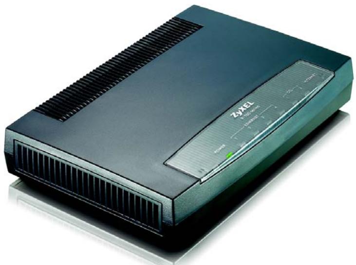
Getting To Know Your P-793H v2
This chapter introduces the main features and applications of your P-793H v2.
1.1 Overview
The P-793H v2 is a secure G.SHDSL.bis bonded broadway gateway that provides high-speed LAN-to-LAN connection and Internet access over the your telephone. It supports symmetrical multi-rate data transmission speed that adjusts the data rate automatically according to the quality of the wire connection.
You can set up your P-793H v2 for high-speed Internet access or for high-speed point-to-point or point-to-2 points connections with other SHDSL models. The P-793H v2 can be used for either IP routing or bridging depending on your network configuration. As a router, the P-793H v2 provides features such as firewall, content filtering and bandwidth management. As a bridge, the P-793H v2 minimizes the configuration changes you have to make in your existing network.
See Appendix A on page 417 for a complete list of features you can configure on your P-793H v2.
1.1.1 High-speed Internet Access with G.SHDSL
The P-793H v2 provides high-speed G.SHDSL Internet access. The G.SHDSL (Single-pair High-speed Digital Subscriber Line) is a symmetrical, bi-directional DSL service that uses your telephone line to provide data rates up to 2.3 Mbits/sec. (The "G." in "G.SHDSL" is defined by the G.991.2 ITU (International
Telecommunication Union) state-of-the-art industry standard). Unlike ADSL or VDSL, G.SHDSL.bis supports the same high speed for transmission and receiving.
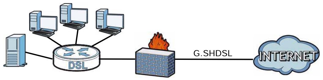
Figure 1 High-speed Internet Access with Your P-793H v2
For Internet access, connect the DSL port to the phone port. Then, connect your computers or servers to the LAN ports for shared Internet access. (See the Quick Start Guide for detailed instructions about hardware connections.) Next, set up the P-793H v2 as a router or as a bridge, depending on the desired configuration.
1.1.2 High-speed Point-to-point Connections
You can use another P-793H v2 or any SHDSL device with the P-793H v2 to create a cost-effective, high-speed connection for high-bandwidth applications such as videoconferencing and distance learning.
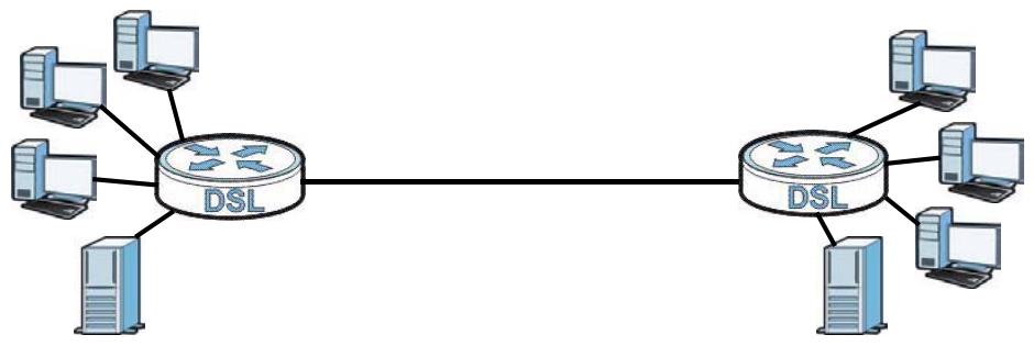
Figure 2 Point-to-point Connections with Your P-793H v2
The P-793H v2s provide a simple, fast point-to-point connection between two geographically-dispersed networks.
1.1.3 High-speed Point-to-2points Connections
Use three P-793H v2s or 2 SHDSL devices with the P-793H v2 to connect two remote networks to a central location. For example, connect the headquarters to
two branch offices. In this scenario the central P-793H v2 acts in a similar way as an Internet service provider.
Figure 3 Point-to-2points Connections with Your P-793H v2
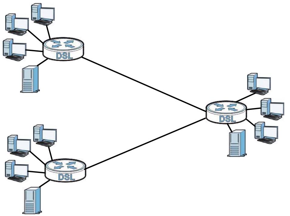
Note: See Chapter 5 on page 67 for more information on setting up point-to-point and point-to-2points connections.
1.2 Ways to Manage the P-793H v2
Use any of the following methods to manage the P-793H v2.
- Web Configurator. This is recommended for everyday management of the P-793H v2 using a (supported) web browser. See Chapter 2 on page 43.
- Command Line Interface. Line commands are mostly used for troubleshooting by service engineers. See Appendix H on page 471.
- SMT. System Management Terminal is a text-based configuration menu that you can use to configure your device. See Chapter 23 on page 301.
- FTP. Use File Transfer Protocol for firmware upgrades and configuration backup/ restore. See Chapter 17 on page 243.
- SNMP. The device can be monitored and/or managed by an SNMP manager. See Chapter 17 on page 243.
- TR-069. This is a standard that defines how your P-793H v2 can be managed by a management server. See Chapter 17 on page 243.
1.3 Good Habits for Managing the P-793H v2
Do the following things regularly to make the P-793H v2 more secure and to manage the P-793H v2 more effectively.
- Change the password. Use a password that's not easy to guess and that consists of different types of characters, such as numbers and letters.
- Write down the password and put it in a safe place.
- Back up the configuration (and make sure you know how to restore it). Restoring an earlier working configuration may be useful if the device becomes unstable or even crashes. If you forget your password, you will have to reset the P-793H v2 to its factory default settings. If you backed up an earlier configuration file, you would not have to totally reconfigure the P-793H v2. You could simply restore your last configuration.
1.4 LEDs
The following figure shows the LEDs.
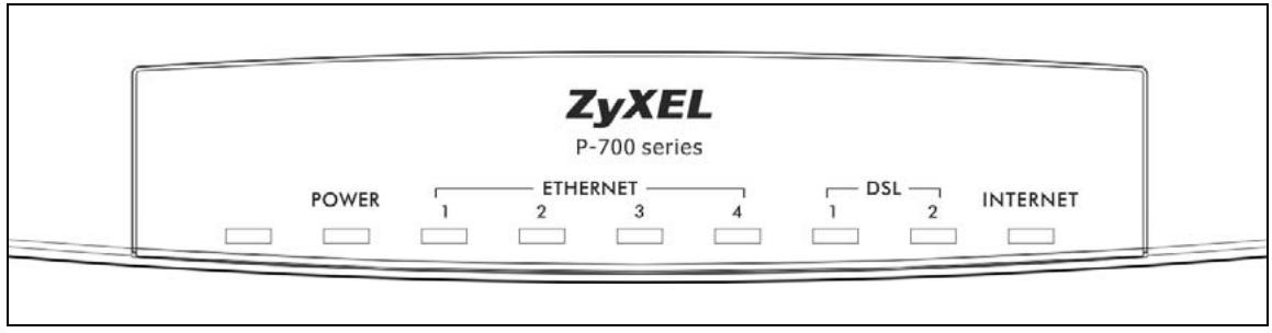
Figure 4 LEDs
The following table describes the LEDs.
Table 1 LEDs
| LED | COLOR | STATUS | DESCRIPTION |
| POWER | Green | On | The P-793H v2 is receiving power and functioning properly. |
| Blinking | The P-793H v2 is rebooting or performing diagnostics. | ||
| Red | On | Power to the P-793H v2 is too low. | |
| Off | The system is not ready or has malfunctioned. | ||
| LAN 1~4 | Green | On | This port has a successful Ethernet connection. |
| Blinking | This port is sending/receiving data. | ||
| Off | This port is not connected. | ||
| DSL1/DSL2 | Green | On | The DSL line is up. |
| Blinking | The P-793H v2 is initializing the DSL line. | ||
| Off | The DSL line is down. | ||
| Note: For Internet access setup or point-to-point connections, the DSL1 and DSL2 LEDs indicate the status of a single connection (act as one LED). For point-to-2point connections, the DSL1 and DSL2 LEDs indicate the status of connection 1 and connection 2 respectively. | |||
| INTERNET | Green | On | The Internet connection is up, and the P-793H v2 has an IP address. (If the P-793H v2 uses RFC 1483 in bridge mode, this light does not turn on, but it does blink when the P-793H v2 is sending/receiving data.) |
| Blinking | The P-793H v2 is sending/receiving data. | ||
| Red | On | The P-793H v2 tried to get an IP address, but an error occurred. | |
| Off | The Internet connection is down. | ||
1.5 The RESET Button
If you forget your password or cannot access the web configurator, you will need to use the RESET button at the back of the device to reload the factory-default configuration file. This means that you will lose all configurations that you had previously and the password will be reset to "1234".
1.5.1 Using the RESET Button
1 Make sure the POWER LED is on (not blinking).
2 To set the device back to the factory default settings, press the RESET button for ten seconds or until the POWER LED begins to blink and then release it. When the POWER LED begins to blink, the defaults have been restored and the device restarts.
Introducing the Web Configurator
2.1 Web Configurator Overview
The web configurator is an HTML-based management interface that allows easy P-793H v2 setup and management via Internet browser. Use Internet Explorer 6.0 and later or Netscape Navigator 7.0 and later versions. The recommended screen resolution is 1024 by 768 pixels.
In order to use the web configurator you need to allow:
- Web browser pop-up windows from your device. Web pop-up blocking is enabled by default in Windows XP SP (Service Pack) 2.
- JavaScripts (enabled by default).
- Java permissions (enabled by default).
See the chapter on troubleshooting if you need to make sure these functions are allowed in Internet Explorer.
2.2 Accessing the Web Configurator
1 Make sure your P-793H v2 hardware is properly connected (refer to the Quick Start Guide).
2 Launch your web browser.
3 Type "192.168.1.1" as the URL.
4 A password screen displays. The P-793H v2 has a dual login system. The default non-readable characters represents the user password (user by default). Clicking Login without entering any password brings you to the system's status screen. To access the administrative web configurator and manage the P-793H v2, type the admin password (1234 by default) in the password screen and click Login. Click Cancel to revert to the default user password in the password field. If you have changed the password, enter your password and click Login.
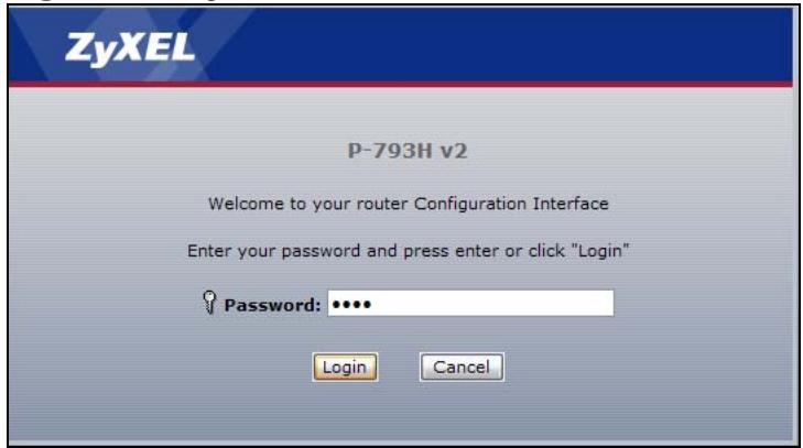
Figure 5 Login Screen
5 The following screen displays if you have not yet changed your password. It is strongly recommended you change the default password. Enter a new password, retype it to confirm and click Apply; alternatively click Ignore to proceed to the main menu if you do not want to change the password now.
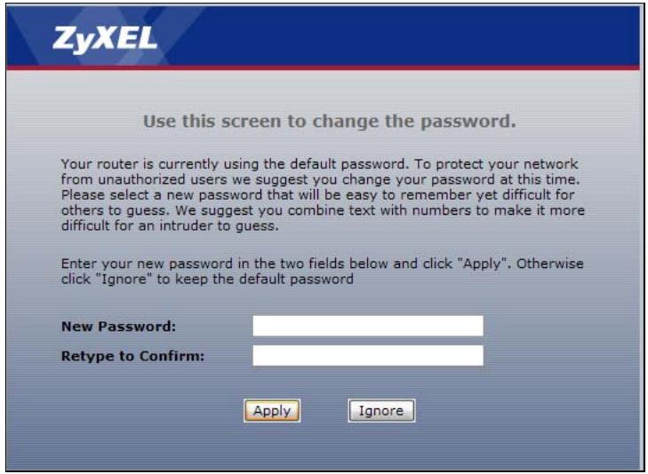
Figure 6 Change Password at Login
6 Select Go to Wizard setup and click Apply to display the wizard main screen. Otherwise, select Go to Advanced setup and click Apply to display the Status screen.
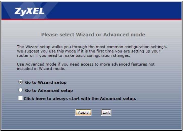
Figure 7 Select a Mode
Note: For security reasons, the P-793H v2 automatically logs you out if you do not use the web configurator for five minutes (default). If this happens, log in again.
2.3 Web Configurator Main Screen
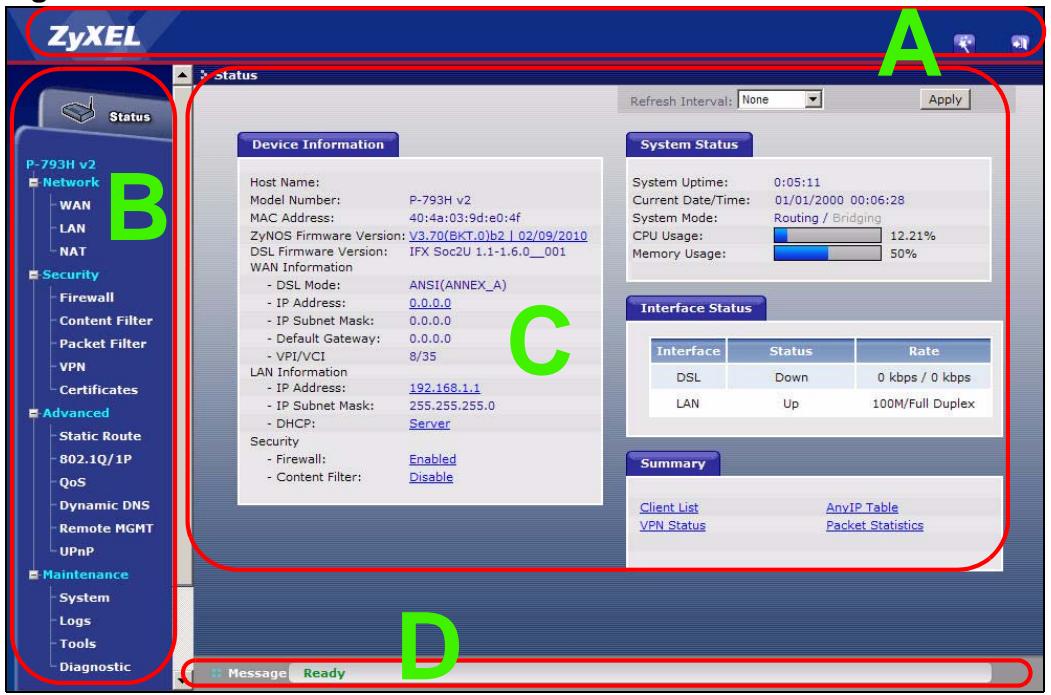
Figure 8 Main Screen
As illustrated above, the main screen is divided into these parts:
A - title bar
B - navigation panel
C - main window
D - status bar
2.3.1 Title Bar
The title bar provides some icons in the upper right corner.

The icons provide the following functions.
Table 2 Web Configurator Icons in the Title Bar
| ICON | DESCRIPTION |
| Wizards: Click this icon to go to the configuration wizards. See Chapter 5 on page 89 for more information. | |
| Logout: Click this icon to log out of the web configurator. |
2.3.2 Navigation Panel
Use the menu items on the navigation panel to open screens to configure P-793H v2 features. The following tables describe each menu item.
Table 3 Navigation Panel Summary
| LINK | TAB | FUNCTION |
| Status | This screen shows the P-793H v2's general device and network status information. Use this screen to access the statistics and client list. | |
| Network | ||
| WAN | Internet Access Setup | Use this screen to configure ISP parameters, WAN IP address assignment, DNS servers and point-to-point or point-to-2point connections. |
| More Connections | Use this screen to configure additional WAN connections. | |
| WAN Backup Setup | Use this screen to configure your traffic redirect properties and WAN backup settings. | |
Table 3 Navigation Panel Summary
| LINK | TAB | FUNCTION |
| LAN | IP | Use this screen to configure LAN TCP/IP settings and other advanced properties. |
| DHCP Setup | Use this screen to configure LAN DHCP settings. | |
| Client List | Use this screen to view current DHCP client information and to always assign specific IP addresses to individual MAC addresses (and host names). | |
| IP Alias | Use this screen to partition your LAN interface into subnets. | |
| NAT | General | Use this screen to enable NAT. |
| Port Forwarding | Use this screen to make your local servers visible to the outside world. This screen appears when you choose SUA Only from the NAT > General screen. | |
| Address Mapping | Use this screen to configure network address translation mapping rules. This screen appears when you choose Full Feature from the NAT > General screen. | |
| ALG | Use this screen to enable or disable SIP ALG. | |
| Security | ||
| Firewall | General | Use this screen to activate/deactivate the firewall and the default action to take on network traffic going in specific directions. |
| Rules | This screen shows a summary of the firewall rules, and allows you to edit/add a firewall rule. | |
| Threshold | Use this screen to configure the thresholds for determining when to drop sessions that do not become fully established. | |
| Content Filter | Keyword | Use this screen to block access to web sites containing certain keywords in the URL. |
| Schedule | Use this screen to set the days and times for the P-793H v2 to perform content filtering. | |
| Trusted | Use this screen to exclude a range of users on the LAN from content filtering on your P-793H v2. | |
| Packet Filter | Packet Filter | Use this screen to configure the rules for protocol and generic filter sets. |
| VPN | Setup | Use this screen to configure each VPN tunnel. |
| Monitor | Use this screen to look at the current status of each VPN tunnel. | |
| VPN Global Setting | Use this screen to allow NetBIOS traffic through VPN tunnels. | |
| Certificates | Trusted CAs | Use this screen to import CA certificates to the P-793H v2. |
| Advanced | ||
Table 3 Navigation Panel Summary
| LINK | TAB | FUNCTION |
| Static Route | Static Route | Use this screen to configure IP static routes to tell your P-793H v2 about networks beyond the directly connected remote nodes. |
| 802.1Q/1P | Group Setting | Use this screen to activate 802.1Q/1P, specify the management VLAN group, display the VLAN groups and configure the settings for each VLAN group. |
| Port Setting | Use this screen to configure the PVID and assign traffic priority for each port. | |
| QoS | General | Use this screen to enable QoS and traffic prioritizing, and configure bandwidth management on the WAN. |
| Class Setup | Use this screen to define a classifier. | |
| Monitor | Use this screen to view each queue's statistics. | |
| Dynamic DNS | Dynamic DNS | This screen allows you to use a static hostname alias for a dynamic IP address. |
| Remote MGMT | WWW | Use this screen to configure through which interface(s) and from which IP address(es) users can use HTTPS or HTTP to manage the P-793H v2. |
| Telnet | Use this screen to configure through which interface(s) and from which IP address(es) users can use Telnet to manage the P-793H v2. | |
| FTP | Use this screen to configure through which interface(s) and from which IP address(es) users can use FTP to access the P-793H v2. | |
| SNMP | Use this screen to configure your P-793H v2's settings for Simple Network Management Protocol management. | |
| DNS | Use this screen to configure through which interface(s) and from which IP address(es) users can send DNS queries to the P-793H v2. | |
| ICMP | Use this screen to set whether or not your P-793H v2 will respond to pings and probes for services that you have not made available. | |
| UPnP | General | Use this screen to turn UPnP on or off. |
| Maintenance | ||
| System | General | Use this screen to configure your P-793H v2's name, domain name, management inactivity timeout and password. |
| Time Setting | Use this screen to change your P-793H v2's time and date. | |
| Logs | View Log | Use this screen to display your P-793H v2's logs. |
| Log Settings | Use this screen to select which logs and/or immediate alerts your P-793H v2 is to record. You can also set it to e-mail the logs to you. | |
Table 3 Navigation Panel Summary
| LINK | TAB | FUNCTION |
| Tools | Firmware | Use this screen to upload firmware to your P-793H v2. |
| Configuration | Use this screen to backup and restore your P-793H v2's configuration (settings) or reset the factory default settings. | |
| Restart | This screen allows you to reboot the P-793H v2 without turning the power off. | |
| Diagnostic | General | Use this screen to test the connections to other devices. |
| DSL Line | These screen displays information to help you identify problems with the DSL connection. |
2.3.3 Main Window
The main window displays information and configuration fields. It is discussed in the rest of this document.
Right after you log in, the Status screen is displayed. See Chapter 3 on page 37 for more information about the Status screen.
2.3.4 Status Bar
Check the status bar when you click Apply or OK to verify that the configuration has been updated.
Status Screens
3.1 Overview
Use the Status screens to look at the current status of the device, system resources, and interfaces (LAN and WAN). The Status screen also provides detailed information of client list, Any IP, VPN and packet statistics.
3.2 The Status Screen
Use this screen to view the status of the P-793H v2. Click Status to open this screen.
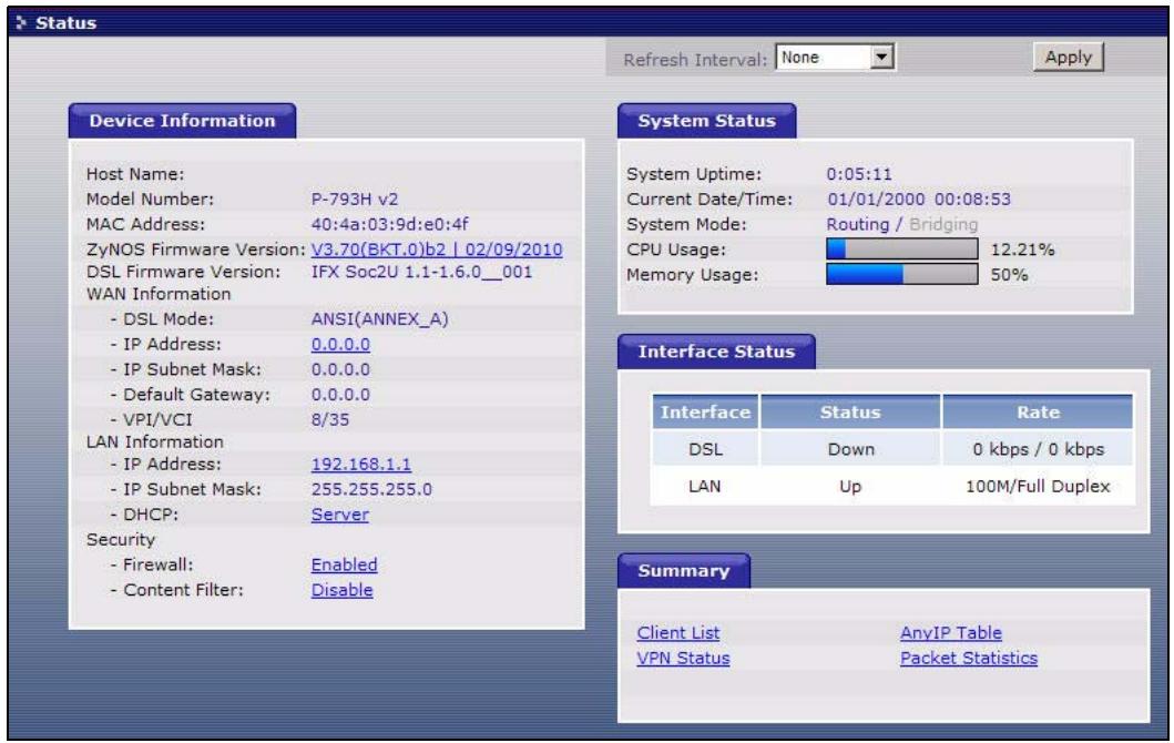
Figure 9 Status Screen
Each field is described in the following table.
Table 4 Status Screen
| LABEL | DESCRIPTION |
| Refresh Interval | Select how often you want the P-793H v2 to update this screen. |
| Apply | Click this to update this screen immediately. |
| Device Information | |
| Host Name | This field displays the P-793H v2 system name. It is used for identification. You can change this in the Maintenance > System > General screen's System Name field. |
| Model Number | This is the model name of your device. |
| MAC Address | This is the MAC (Media Access Control) or Ethernet address unique to your P-793H v2. |
| ZyNOS Firmware Version | This is the current version of the firmware inside the device. It also shows the date the firmware version was created. Click this to go to the screen where you can change it. |
| DSL Firmware Version | This is the current version of the device's DSL modem code. |
| WAN Information | |
| DSL Mode | This is the DSL standard that your P-793H v2 is using. |
| IP Address | This is the current IP address of the P-793H v2 in the WAN. Click this to go to the screen where you can change it. |
| IP Subnet Mask | This is the current subnet mask in the WAN. |
| Default Gateway | This is the IP address of the default gateway, if applicable. |
| VPI/VCI | This is the Virtual Path Identifier and Virtual Channel Identifier that you entered in the wizard or WAN screen. |
| LAN Information | |
| IP Address | This is the current IP address of the P-793H v2 in the LAN. Click this to go to the screen where you can change it. |
| IP Subnet Mask | This is the current subnet mask in the LAN. |
| DHCP | This field displays what DHCP services the P-793H v2 is providing to the LAN. Choices are: Server - The P-793H v2 is a DHCP server in the LAN. It assigns IP addresses to other computers in the LAN. Relay - The P-793H v2 acts as a surrogate DHCP server and relays DHCP requests and responses between the remote server and the clients. None - The P-793H v2 is not providing any DHCP services to the LAN. Click this to go to the screen where you can change it. |
| Security | |
| Firewall | This displays whether or not the P-793H v2's firewall is activated. Click this to go to the screen where you can change it. |
Table 4 Status Screen
| LABEL | DESCRIPTION |
| Content Filter | This displays whether or not the P-793H v2's content filtering is activated. Click this to go to the screen where you can change it. |
| System Status | |
| System Uptime | This field displays how long the P-793H v2 has been running since it last started up. The P-793H v2 starts up when you plug it in, when you restart it (Maintenance > Tools > Restart), or when you reset it. |
| Current Date/Time | This field displays the current date and time in the P-793H v2. You can change this in Maintenance > System > Time Setting. |
| System Mode | This displays whether the P-793H v2 is functioning as a router or a bridge. |
| CPU Usage | This field displays what percentage of the P-793H v2's processing ability is currently used. When this percentage is close to 100%, the P-793H v2 is running at full load, and the throughput is not going to improve anymore. If you want some applications to have more throughput, you should turn off other applications (for example, using QoS; see Chapter 15 on page 217). |
| Memory Usage | This field displays what percentage of the P-793H v2's memory is currently used. Usually, this percentage should not increase much. If memory usage does get close to 100%, the P-793H v2 is probably becoming unstable, and you should restart the device. See Section 21.4 on page 295, or turn off the device (unplug the power) for a few seconds. |
| Interface Status | |
| Interface | This column displays each interface the P-793H v2 has. |
| Status | This field indicates whether or not the P-793H v2 is using the interface. For the DSL interface, this field displays Down (line is down), Up (line is up or connected) if you're using Ethernet encapsulation and Down (line is down), Up (line is up or connected), Idle (line (ppp) idle), Dial (starting to trigger a call) and Drop (dropping a call) if you're using PPPoE encapsulation. For the LAN interface, this field displays Up when the P-793H v2 is using the interface and Down when the P-793H v2 is not using the interface. |
| Rate | For the LAN interface, this displays the port speed and duplex setting. For the DSL interface, it displays the downstream and upstream transmission rate. |
| Summary | |
| Client List | Click this link to view current DHCP client information. See Section 7.4 on page 108. |
| VPN Status | Click this link to view the status of any VPN tunnels the P-793H v2 has negotiated. See Section 3.4 on page 54. |
| AnyIP Table | Click this link to view a list of IP addresses and MAC addresses of computers, which are not in the same subnet as the P-793H v2. See Section 3.5 on page 54. |
| Packet Statistics | Click this link to view port status and packet specific statistics. See Section 3.6 on page 55. |
3.3 Client List
See Section 7.4 on page 108 for information on this screen.
3.4 Status: VPN Status
See Section Figure 75 on page 178 for information on this screen.
3.5 Any IP Table
Click Status > AnyIP Table to access this screen. Use this screen to view the IP address and MAC address of each computer that is using the P-793H v2 but is in a different subnet than the P-793H v2.
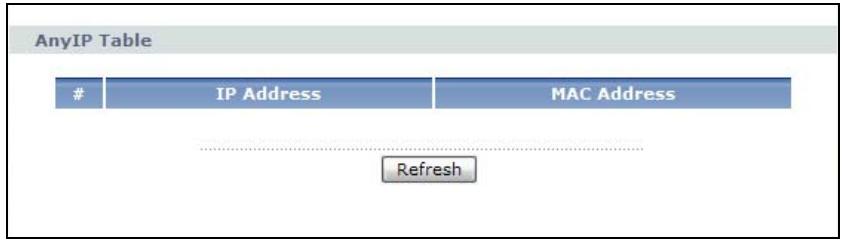
Figure 10 Any IP Table
Each field is described in the following table.
Table 5 Any IP Table
| LABEL | DESCRIPTION |
| # | This field is a sequential value. It is not associated with a specific entry. |
| IP Address | This field displays the IP address of each computer that is using the P-793H v2 but is in a different subnet than the P-793H v2. |
| MAC Address | This field displays the MAC address of the computer that is using the P-793H v2 but is in a different subnet than the P-793H v2. |
| Refresh | Click this to update this screen. |
3.6 Packet Statistics
Read-only information here includes port status and packet specific statistics. Also provided are "system up time" and "poll interval(s)". The Poll Interval(s) field is configurable. Click Status > Packet Statistics to access this screen.
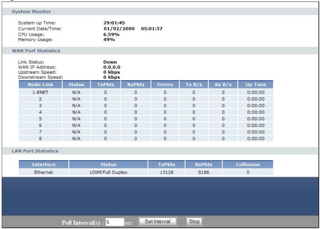
Figure 11 Packet Statistics
The following table describes the fields in this screen.
Table 6 Packet Statistics
| LABEL | DESCRIPTION |
| System Monitor | |
| System up Time | This is the elapsed time the system has been up. |
| Current Date/Time | This field displays your P-793H v2's present date and time. |
| CPU Usage | This field specifies the percentage of CPU utilization. |
| Memory Usage | This field specifies the percentage of memory utilization. |
| WAN Port Statistics | |
| Link Status | This is the status of your WAN link. |
| WAN IP Address | This is the IP address of the P-793H v2's WAN port. |
| Upstream Speed | This is the upstream speed of your P-793H v2. |
| Downstream Speed | This is the downstream speed of your P-793H v2. |
| Node-Link | This field displays the remote node index number and link type. Link types are PPPoA, ENET, RFC 1483 and PPPoE. |
| Status | This field displays Down (line is down), Up (line is up or connected) if you're using Ethernet encapsulation and Down (line is down), Up (line is up or connected), Idle (line (ppp) idle), Dial (starting to trigger a call) and Drop (dropping a call) if you're using PPPoE encapsulation. |
| TxPkts | This field displays the number of packets transmitted on this port. |
| RxPkts | This field displays the number of packets received on this port. |
| Errors | This field displays the number of error packets on this port. |
| Tx B/s | This field displays the number of bytes transmitted in the last second. |
| Rx B/s | This field displays the number of bytes received in the last second. |
| Up Time | This field displays the elapsed time this port has been up. |
| LAN Port Statistics | |
| Interface | This field displays Ethernet (LAN ports). |
| Status | For the LAN ports, this field displays Down (line is down) or Up (line is up or connected). |
| TxPkts | This field displays the number of packets transmitted on this interface. |
| RxPkts | This field displays the number of packets received on this interface. |
| Collisions | This is the number of collisions on this interfaces. |
| Poll Interval(s) | Type the time interval for the browser to refresh system statistics. |
| Set Interval | Click this to apply the new poll interval you entered in the Poll Interval field above. |
| Stop | Click this to halt the refreshing of the system statistics. |
Internet Setup Wizard
4.1 Overview
Use the wizard setup screens to configure your system for Internet access with the information given to you by your ISP.
Note: See the advanced menu chapters for background information on these fields.
4.2 Internet Access Wizard Setup
1 After you enter the password to access the web configurator, select Go to Wizard setup and click Apply. Otherwise, click the wizard icon ( ) in the top right corner of the web configurator to go to the wizards.
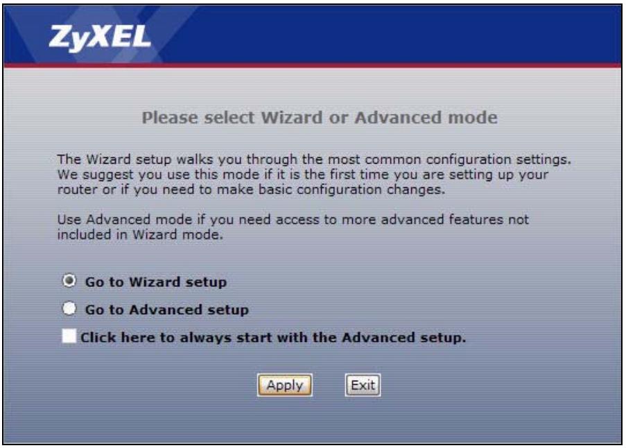
Figure 12 Select a Mode
2 Click INTERNET SETUP to configure the system for Internet access.
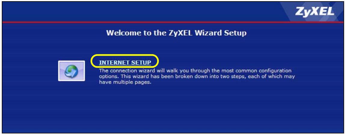
Figure 13 Wizard Welcome
3 Your P-793H v2 attempts to detect your DSL connection and your connection type.
3a The following screen appears if a connection is not detected. Check your hardware connections and click Restart the INTERNET SETUP Wizard to return to the wizard welcome screen. If you still cannot connect, click Manually configure your Internet connection. Follow the directions in the wizard and enter your Internet setup information as provided to you by your ISP. See Section 4.2.1 on page 60 for more details.
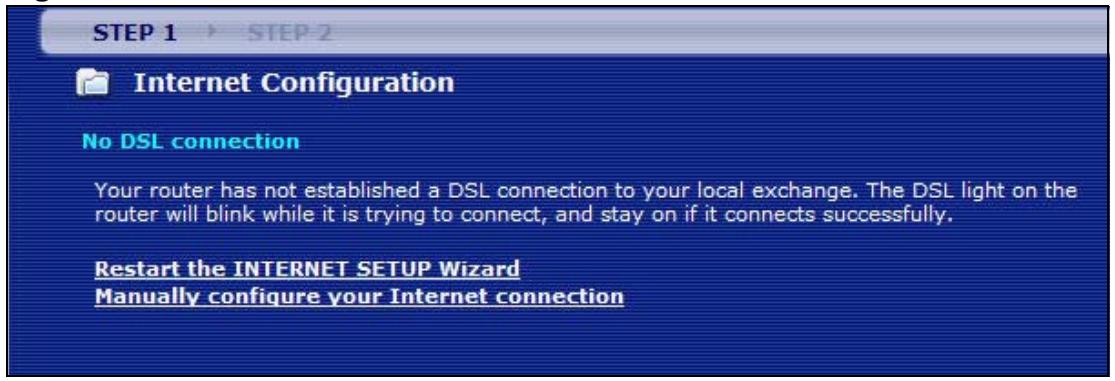
Figure 14 Auto Detection: No DSL Connection
3b The following screen displays if a PPPoE or PPPoA connection is detected. Enter your Internet account information (username, password and/or service name) exactly as provided by your ISP. Then click Next.
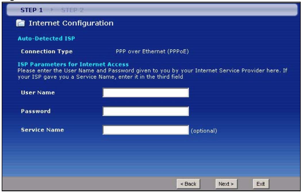
Figure 15 Auto-Detection: PPPoE
3c The following screen appears if the ZyXEL device detects a connection but not the connection type. Click Next and refer to Section 4.2.1 on page 60 on how to manually configure the P-793H v2 for Internet access.
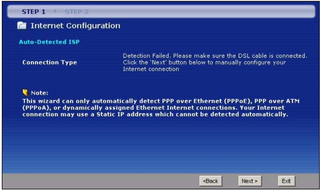
Figure 16 Auto Detection: Failed
4.2.1 Manual Configuration
1 If the P-793H v2 fails to detect your DSL connection type but the physical line is connected, enter your Internet access information in the wizard screen exactly as your service provider gave it to you. Leave the defaults in any fields for which you were not given information.
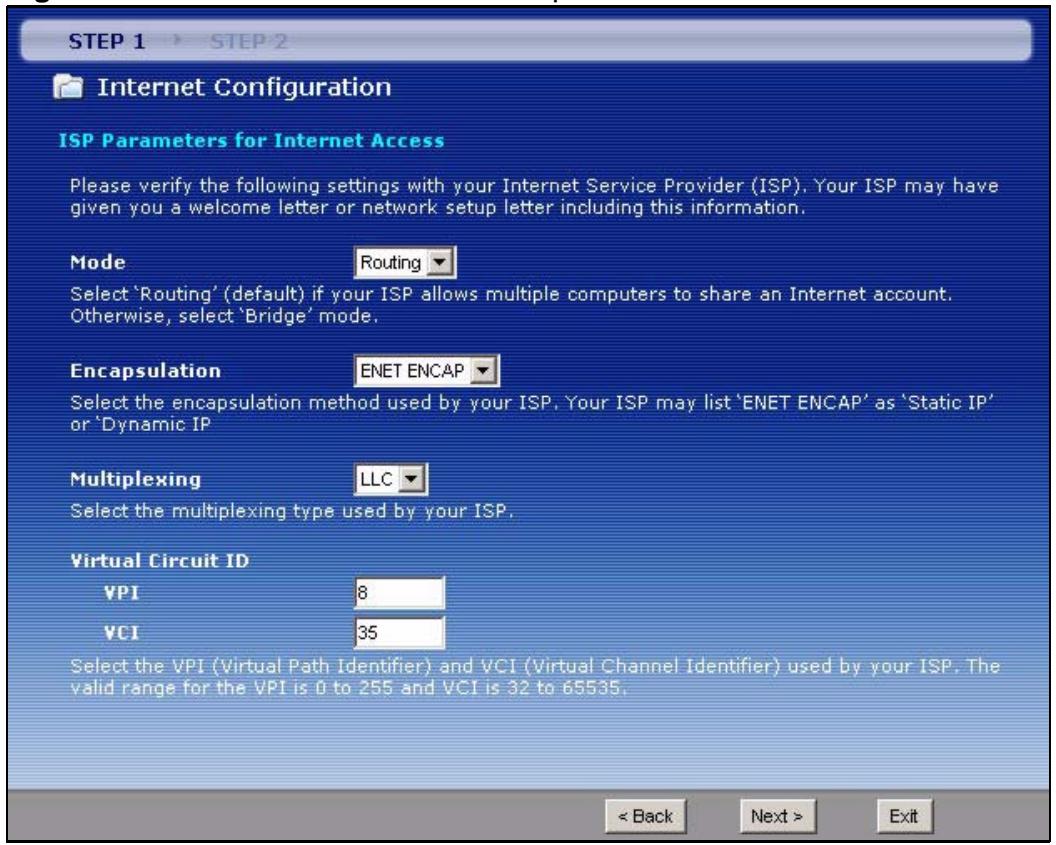
Figure 17 Internet Access Wizard Setup: ISP Parameters
The following table describes the fields in this screen.
Table 7 Internet Access Wizard Setup: ISP Parameters
| LABEL | DESCRIPTION |
| Mode | Select Routing (default) from the drop-down list box if your ISP give you one IP address only and you want multiple computers to share an Internet account. Select Bridge when your ISP provides you more than one IP address and you want the connected computers to get individual IP address from ISP's DHCP server directly. If you select Bridge, you cannot use Firewall, DHCP server and NAT on the P-793H v2. |
| Encapsulation | Select the encapsulation type your ISP uses from the Encapsulation drop-down list box. Choices vary depending on what you select in the Mode field. If you select Bridge in the Mode field, select either PPPoA or RFC 1483. If you select Routing in the Mode field, select PPPoA, RFC 1483, ENET ENCAP or PPPoE. |
Table 7 Internet Access Wizard Setup: ISP Parameters
| LABEL | DESCRIPTION |
| Multiplexing | Select the multiplexing method used by your ISP from the Multiplex drop-down list box either VC-based or LLC-based. |
| Virtual Circuit ID | VPI (Virtual Path Identifier) and VCI (Virtual Channel Identifier) define a virtual circuit. Refer to the appendix for more information. |
| VPI | Enter the VPI assigned to you. This field may already be configured. |
| VCI | Enter the VCI assigned to you. This field may already be configured. |
| Back | Click this to return to the previous screen without saving. |
| Next | Click this to continue to the next wizard screen. The next wizard screen you see depends on what protocol you chose above. |
| Exit | Click this to close the wizard screen without saving. |
2 The next wizard screen varies depending on what mode and encapsulation type you use. All screens shown are with routing mode. Configure the fields and click Next to continue.
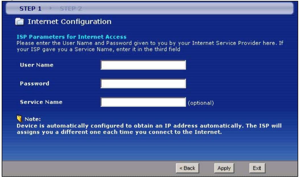
Figure 18 Internet Connection with PPPoE
The following table describes the fields in this screen.
Table 8 Internet Connection with PPPoE
| LABEL | DESCRIPTION |
| User Name | Enter the user name exactly as your ISP assigned. If assigned a name in the form user@domain where domain identifies a service name, then enter both components exactly as given. |
| Password | Enter the password associated with the user name above. |
| Service Name | Type the name of your PPPoE service here. |
| Back | Click this to return to the previous screen without saving. |
| Apply | Click this to save your changes. |
| Exit | Click this to close the wizard screen without saving. |
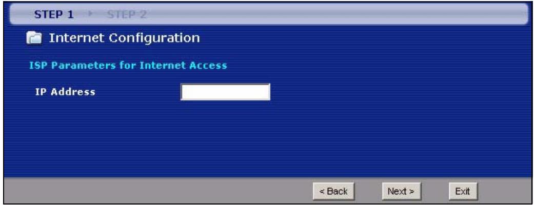
Figure 19 Internet Connection with RFC 1483
The following table describes the fields in this screen.
Table 9 Internet Connection with RFC 1483
| LABEL | DESCRIPTION |
| IP Address | This field is available if you select Routing in the Mode field. Type your ISP assigned IP address in this field. |
| Back | Click this to return to the previous screen without saving. |
| Next | Click this to continue to the next wizard screen. |
| Exit | Click this to close the wizard screen without saving. |
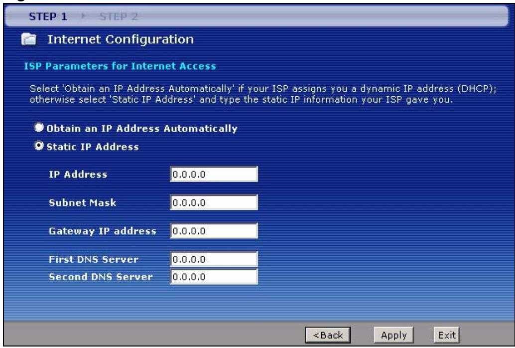
Figure 20 Internet Connection with ENET ENCAP
The following table describes the fields in this screen.
Table 10 Internet Connection with ENET ENCAP
| LABEL | DESCRIPTION |
| Obtain an IP Address Automatically | A static IP address is a fixed IP that your ISP gives you. A dynamic IP address is not fixed; the ISP assigns you a different one each time you connect to the Internet. Select Obtain an IP Address Automatically if you have a dynamic IP address. |
| Static IP Address | Select Static IP Address if your ISP gave you an IP address to use. |
| IP Address | Enter your ISP assigned IP address. |
| Subnet Mask | Enter a subnet mask in dotted decimal notation. Refer to the appendix to calculate a subnet mask If you are implementing subnetting. |
| Gateway IP address | You must specify a gateway IP address (supplied by your ISP) when you use ENET Encapsulation field in the previous screen. |
| First DNS Server | Enter the IP addresses of the DNS servers. The DNS servers are passed to the DHCP clients along with the IP address and the subnet mask. |
| Second DNS Server | As above. |
| Back | Click this to return to the previous screen without saving. |
| Apply | Click this to save your changes. |
| Exit | Click this to close the wizard screen without saving. |
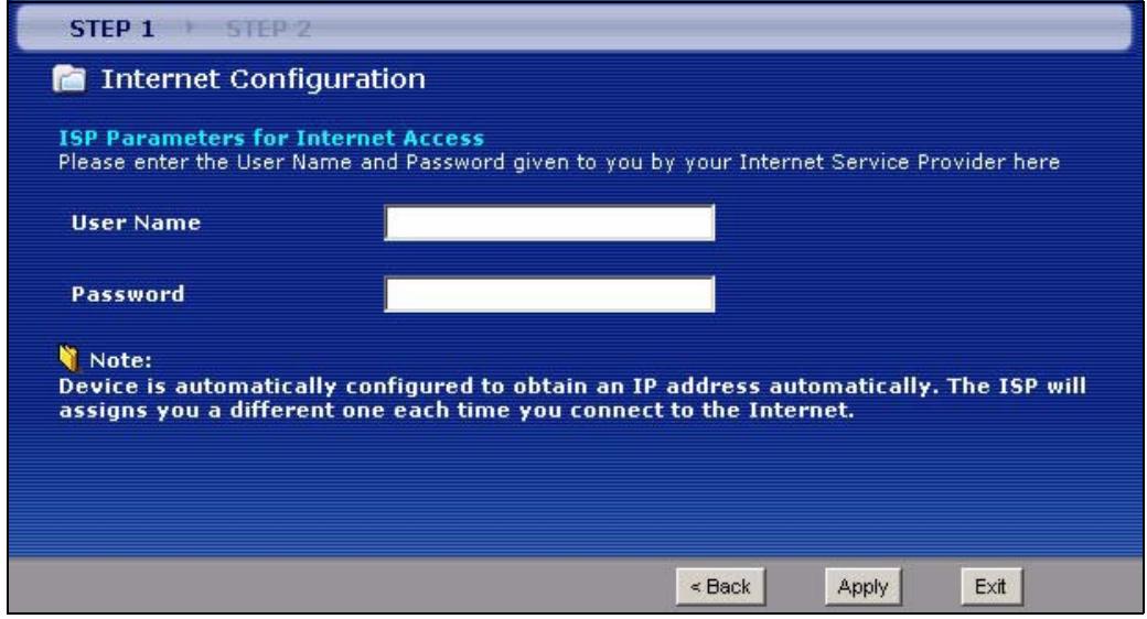
Figure 21 Internet Connection with PPPoA
The following table describes the fields in this screen.
Table 11 Internet Connection with PPPoA
| LABEL | DESCRIPTION |
| User Name | Enter the login name that your ISP gives you. |
| Password | Enter the password associated with the user name above. |
| Back | Click this to return to the previous screen without saving. |
| Apply | Click this to save your changes. |
| Exit | Click this to close the wizard screen without saving. |
3 Use the read-only summary table to check whether what you have configured is correct. Click Finish to complete and save the wizard setup.
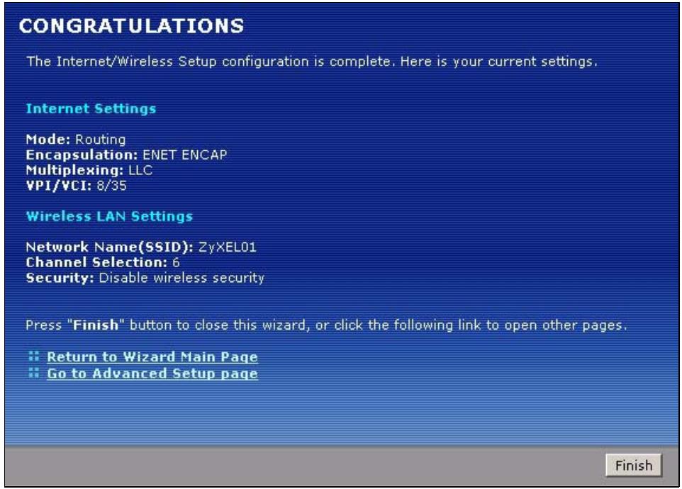
Figure 22 Internet Access Setup Complete
4 Launch your web browser and navigate to www.zyxel.com. Internet access is just the beginning. Refer to the rest of this guide for more detailed information on the complete range of P-793H v2 features. If you cannot access the Internet, open the web configurator again to confirm that the Internet settings you configured in the wizard setup are correct.
5.1 Overview
This chapter describes:
- Configuring Point-to-point Connection, see page 67
- Configuring a Point-to-2points Connection, see page 70
Note: The tutorials featured in this chapter require a basic understanding of connecting to and using the Web Configurator on your P-793H v2. For details, see the included Quick Start Guide. For field descriptions of individual screens, see the related technical reference in this User's Guide.
5.2 Configuring Point-to-point Connection
In this scenario, Company A wants to set up a point-to-point connection with its branch office B by using two P-793H v2s. The two P-793H v2s are directly connected together through their DSL ports. The P-793H v2 on A's side is the server and the P-793H v2 on B's side is the client. The maximum transfer rate for the DSL connection between A and B is 5696 Kbps and the minimum transfer rate is 3200 Kbps.
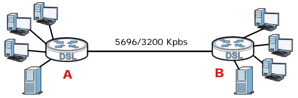
To set up the point-to-point connection between A and B , you need to:
1 Set Up the Server.
2 Set Up the Client.
3 Connect the P-793H v2s.
5.2.1 Set Up the Server
1 Log in to the server P-793H v2 of Company A.
2 Click Network > WAN > Internet Access Setup.
3 Configure the Internet Access Setup screen as the following. Select ATM as the Transfer Mode. Select Bridge as the Mode. Configure the Multiplexing,
Encapsulation, VPI, and VCI fields for the point-to-point connection. Select 1 in the Line field as the DSL line you want the P-793H v2 to use as a default for outgoing traffic.
4 Then configure the Service Type section. Select 2 wire in the Service Mode field. In the Service Type field, select Server. Select 5696 as the Transfer Max Rate and 3200 as the Transfer Min Rate. Leave the rest of the fields set to their default settings. Click Apply.
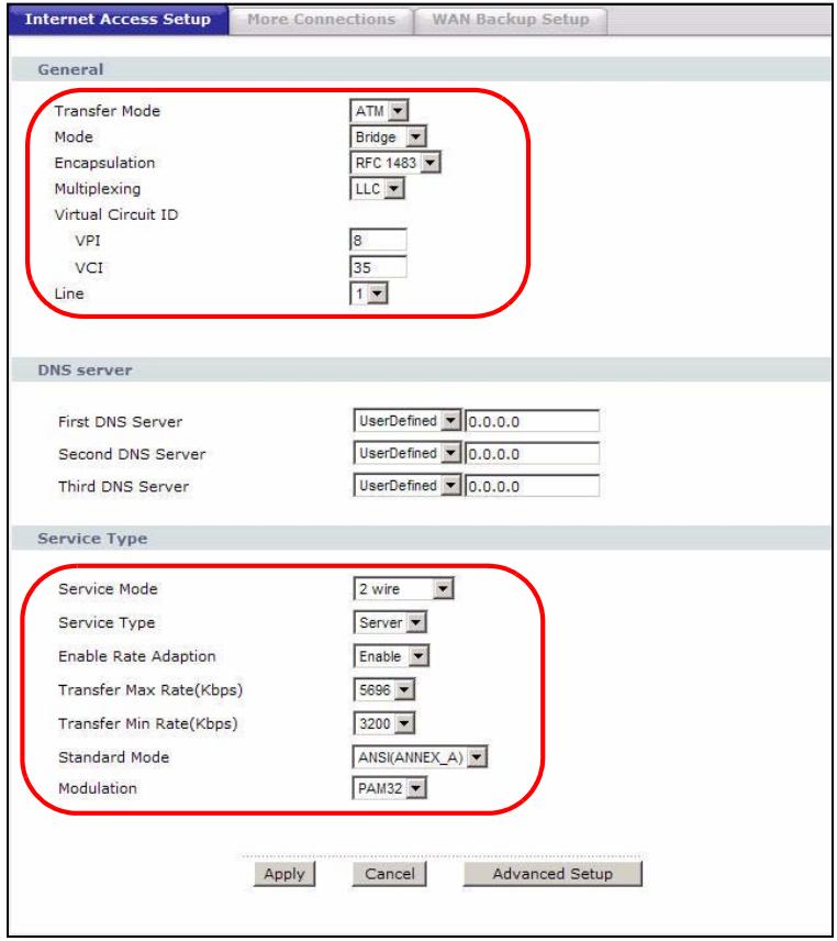
Figure 23 WAN > Internet Access Setup
5.2.2 Set Up the Client
1 Log in to the client P-793H v2 of branch office B.
2 Click Network > WAN > Internet Access Setup.
3 Select ATM as the Transfer Mode. Select Bridge as the Mode. Set the Multiplexing, Encapsulation, VPI, and VCI to the same values you set in the server. Select 1 in the Line field as the DSL line you want the P-793H v2 to use as a default for outgoing traffic.
4 Scroll down to the Service Type section. In the Service Mode field, select 2 wire, the same type of connection you selected for the server. In the Service Type field, select Client. The rest of the fields will be negotiated with the server. Click Apply.
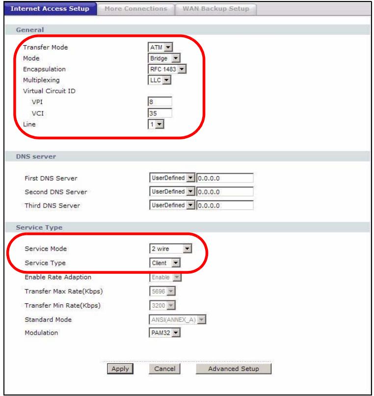
5.2.3 Connect the P-793H v2s
Connect the DSL ports on the P-793H v2s together, and wait while the P-793H v2s automatically establish the connection. When the connection is established, the DSL1, DSL2, and INTERNET lights are on. It takes up to half a minute to establish the connection. If the P-793H v2s do not establish the connection, verify that the settings (except the Service Type) match.
5.3 Configuring a Point-to-2points Connection
Now Company A has another branch office, C and wants to set up a point-to-2points connection between a server P-793H v2 on A's side and client P-793H v2s at B and C. The maximum transfer rate for the DSL connection between A and B is 5696 Kbps and the minimum transfer rate is 3200 Kbps. The maximum transfer rate for the DSL connection between A and C is 2560 Kbps and minimum transfer rate is 1280 Kbps.
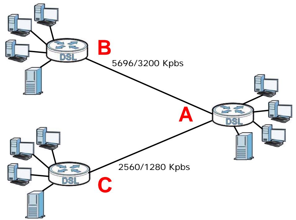
To set up the point-to-2 point connection between A , B and C you need to:
1 Set up the Server.
2 Set up the Clients.
3 Connect the P-793H v2s.
5.3.1 Set up the Server
1 Log in to the server P-793H v2 of Company A.
2 Click Network > WAN > Internet Access Setup.
3 Configure the Internet Access Setup screen as the following. Select ATM as the Transfer Mode. Select Bridge as the Mode. Configure the Multiplexing, Encapsulation, VPI, and VCI fields for the point-to-point connection. Select 1 in the Line field as the DSL line you want the P-793H v2 to use as a default for outgoing traffic.
4 Then configure the Service Type section. Select 2 wire-2 line in the Service Mode field. In the Service Type field, select Server. For Line1 configuration, select 5696 as the Transfer Max Rate and 3200 as the Transfer Min Rate. For Line2 configuration, select 2560 as the Transfer Max Rate and 1280 as the Transfer Min Rate. Leave the rest of the fields to their default settings. Click Apply.
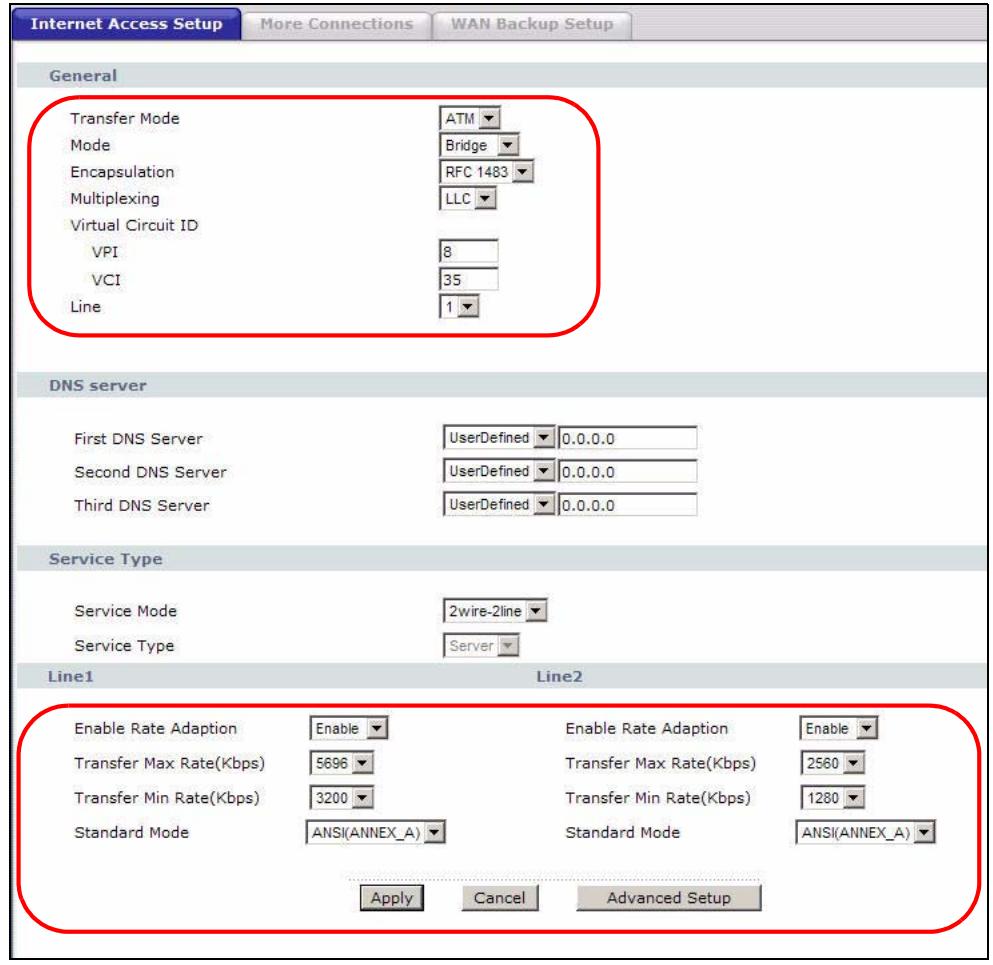
Figure 24 WAN > Internet Access Setup
5.3.2 Set up the Clients
1 Log in to the client P-793H v2 of branch office B.
2 Click Network > WAN > Internet Access Setup.
3 Select ATM as the Transfer Mode. Set the VPI, VCI, Multiplexing, and Encapsulation to the same values you set in the server.
4 Scroll down to the Service Type section. In the Service Mode field, select 2 wire. In the Service Type field, select Client. The rest of the fields will be negotiated with the server. Click Apply.
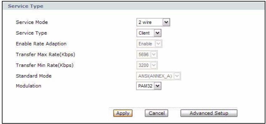
Figure 25 WAN > Internet Connection > Service Type of B
5 Repeat the above steps 1 to 4 for the second client P-793H v2 on C's side. The Service Type should look like the following.
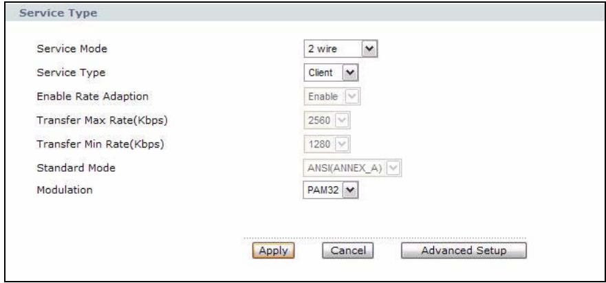
Figure 26 WAN > Internet Connection > Service Type of C
5.3.3 Connect the P-793H v2s
Connect the DSL ports on the P-793H v2s together, and wait while the P-793H v2s automatically establish the connection. Make sure that the Y-cable is connected to the proper DSL outlets. The Y-cable connector marked DSL1 must be connected to the outgoing DSL 1 telephone jack and the Y-cable connector marked DSL2 must be connected to the outgoing DSL 2 telephone jack.
When the connection is established, the DSL1, DSL2, and INTERNET lights turn on. It takes up to half a minute to establish the connection. If the P-793H v2s do not establish the connection, verify that the settings are correct.
PART II
Technical Reference
6.1 Overview
This chapter describes how to configure WAN settings from the WAN screens. Use these screens to configure your P-793H v2 for Internet access.
A WAN (Wide Area Network) connection is an outside connection to another network or the Internet. It connects your private networks (such as a LAN (Local Area Network) and other networks, so that a computer in one location can communicate with computers in other locations.
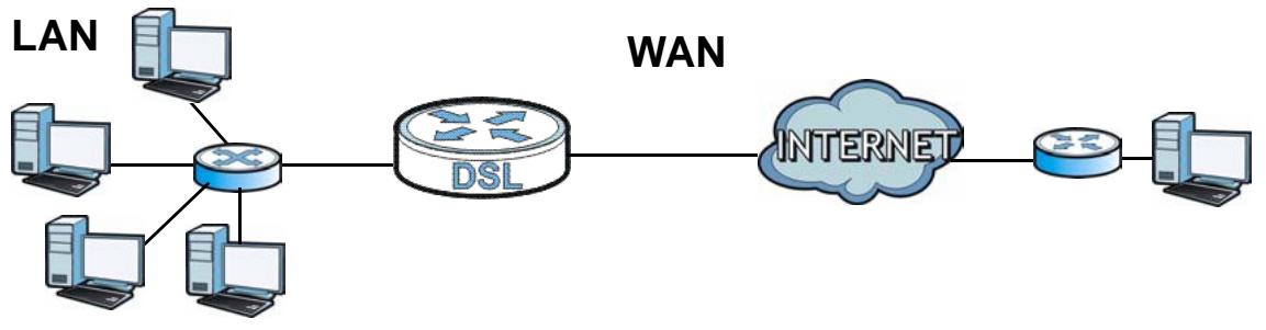
Figure 27 LAN and WAN
6.1.1 What You Can Do in the WAN Screens
- Use the Internet Access Setup screen (Section 6.2 on page 78) to configure the WAN settings on the P-793H v2 for Internet access.
- Use the More Connections screen (Section 6.3 on page 86) to set up additional Internet access connections.
- Use the WAN Backup Setup screen (Section 6.4 on page 92) to set up a backup gateway that helps forward traffic to its destination when the default WAN connection is down.
6.1.2 What You Need to Know About WAN
Encapsulation Method
Encapsulation is used to include data from an upper layer protocol into a lower layer protocol. To set up a WAN connection to the Internet, you need to use the same encapsulation method used by your ISP (Internet Service Provider). If your ISP offers a dial-up Internet connection using PPPoE (PPP over Ethernet) or PPPoA, they should also provide a username and password (and service name) for user authentication.
WAN IP Address
The WAN IP address is an IP address for the P-793H v2, which makes it accessible from an outside network. It is used by the P-793H v2 to communicate with other devices in other networks. It can be static (fixed) or dynamically assigned by the ISP each time the P-793H v2 tries to access the Internet.
If your ISP assigns you a static WAN IP address, they should also assign you the subnet mask and DNS server IP address(es) (and a gateway IP address if you use the Ethernet or ENET Encapsulation method).
ATM
Asynchronous Transfer Mode (ATM) is a LAN and WAN networking technology that provides high-speed data transfer. ATM uses fixed-size packets of information called cells. With ATM, a high QoS (Quality of Service) can be guaranteed. ATM uses a connection-oriented model and establishes a virtual circuit (VC) between two endpoints before the actual data exchange begins.
PTM
Packet Transfer Mode (PTM) is packet-oriented and supported by the VDSL2 standard. In PTM, packets are encapsulated directly in the High-level Data Link Control (HDLC) frames. It is designed to provide a low-overhead, transparent way of transporting packets over DSL links, as an alternative to ATM.
Multicast
Traditionally, IP packets are transmitted in one of either two ways - Unicast (1 sender - 1 recipient) or Broadcast (1 sender - everybody on the network). Multicast delivers IP packets to a group of hosts on the network - not everybody and not just one.
IGMP
IGMP (Internet Group Multicast Protocol) is a network-layer protocol used to establish membership in a Multicast group - it is not used to carry user data. There are three versions of IGMP. IGMP version 2 and 3 are improvements over version 1, but IGMP version 1 and 2 are still in wide use.
Finding Out More
See Section 6.5 on page 93 for technical background information on WAN.
6.1.3 Before You Begin
You need to know your Internet access settings such as encapsulation and WAN IP address. Get this information from your ISP.
6.2 The Internet Access Setup Screen
Use this screen to change your P-793H v2's WAN settings. Click Network > WAN > Internet Access Setup. The screen differs by the WAN type and encapsulation you select.
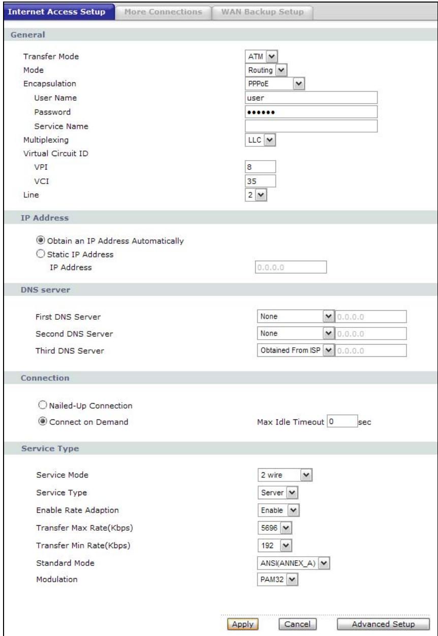
Figure 28 Network > WAN > Internet Access Setup
The following table describes the labels in this screen.
Table 12 Network > WAN > Internet Access Setup
| LABEL | DESCRIPTION |
| General | |
| Transfer Mode | Select the transfer mode you want to use.PTM(Packet Transfer Mode):The P-793H v2 uses the SHDSL technology for data transmission over the DSL port.ATM(Asynchronous Transfer Mode):The P-793H v2 uses the ADSL technology for data transmission over the DSL port. |
| Mode | Select Routing (default) from the drop-down list box if your ISP gives you one IP address only and you want multiple computers to share an Internet account. Select Bridge when your ISP provides you more than one IP address and you want the connected computers to get individual IP address from ISP's DHCP server directly. If you select Bridge, you cannot use Firewall, DHCP server and NAT on the P-793H v2. |
| Encapsulation | Select the method of encapsulation used by your ISP from the drop-down list box. Choices vary depending on the mode you select in the Mode field.If you select Bridge in the Mode field, select either PPPoA or RFC 1483.If you select Routing in the Mode field, select PPPoA, RFC 1483,ENET ENCAP or PPPoE.If you set up a point-to-point or a point-to-2points connection, select either ENET ENCAP or RFC 1483. |
| User Name | (PPPoA and PPPoE encapsulation only) Enter the user name exactly as your ISP assigned. If assigned a name in the form user@domain where domain identifies a service name, then enter both components exactly as given. |
| Password | (PPPoA and PPPoE encapsulation only) Enter the password associated with the user name above. |
| Service Name | (PPPoE only) Type the name of your PPPoE service here. |
| Multiplexing | Select the method of multiplexing used by your ISP from the drop-down list. Choices are VC or LLC.This is available only when you select ATM in the Transfer Mode field. |
| Virtual Circuit ID | VPI(Virtual Path Identifier) and VCI(Virtual Channel Identifier) define a virtual circuit. Refer to the appendix for more information.This is available only when you select ATM in the Transfer Mode field. |
| VPI | The valid range for the VPI is 0 to 255. Enter the VPI assigned to you. |
| VCI | The valid range for the VCI is 32 to 65535 (0 to 31 is reserved for local management of ATM traffic). Enter the VCI assigned to you. |
| Tag VLAN ID for egree packets | Select this option to add the VLAN tag (specified below) to the outgoing traffic through this connection. This is available only when you select PTM in the Transfer Mode field. |
| Enter 802.1P Priority | IEEE 802.1p defines up to 8 separate traffic types by inserting a tag into a MAC-layer frame that contains bits to define class of service. Type the IEEE 802.1p priority level (from 0 to 7) to add to traffic through this connection. The greater the number, the higher the priority level. |
| Enter 802.1Q VLAN ID | Type the VLAN ID number (from 1 to 4094) for traffic through this connection. |
| Line | Select the DSL line you want the P-793H v2 to use as a default for outgoing traffic (remote node 1). |
| IP Address | This option is available if you select Routing in the Mode field. A static IP address is a fixed IP that your ISP gives you. A dynamic IP address is not fixed; the ISP assigns you a different one each time you connect to the Internet. Select Obtain an IP Address Automatically if you have a dynamic IP address; otherwise select Static IP Address and type your ISP assigned IP address in the IP Address field below. |
| Subnet Mask | This option is available if you select ENET ENCAP in the Encapsulation field. Enter a subnet mask in dotted decimal notation. |
| Gateway IP address | This option is available if you select ENET ENCAP in the Encapsulation field. Specify a gateway IP address (supplied by your ISP). |
| DNS Server | |
| First DNS Server Second DNS Server Third DNS Server | Select Obtained From ISP if your ISP dynamically assigns DNS server information (and the P-793H v2's WAN IP address) and you select Obtain an IP Address Automatically. Select User-Defined if you have the IP address of a DNS server. Enter the DNS server's IP address in the field to the right. If you chose User-Defined, but leave the IP address set to 0.0.0.0, User-Defined changes to None after you click Apply. If you set a second choice to User-Defined, and enter the same IP address, the second User-Defined changes to None after you click Apply. Select None if you do not want to configure DNS servers. You must have another DNS server on your LAN, or else the computers must have their DNS server addresses manually configured. If you do not configure a DNS server, you must know the IP address of a computer in order to access it. |
| Connection (PPPoA and PPPoE encapsulation only) | |
| Nailed-Up Connection | Select Nailed-Up Connection when you want your connection up all the time. The P-793H v2 will try to bring up the connection automatically if it is disconnected. |
| Connect on Demand | Select Connect on Demand when you don't want the connection up all the time and specify an idle time-out in the Max Idle Timeout field. |
| Max Idle Timeout | Specify an idle time-out in the Max Idle Timeout field when you select Connect on Demand. The default setting is 0, which means the Internet session will not timeout. |
| Service Type | |
| Service Mode | Select 2-wire, 4-wire or 2wire-2line mode for the DSL connection. This is depends on the network configuration you want to set up and the phone lines you use. Service mode affects the maximum speed of the connection. In 2-wire mode, the maximum data rate is up to 5.69 Mbps, while in 4-wire mode, the maximum data rate is up to 11.38 Mbps. In 2wire-2line mode the maximum data rate is 5.69 Mbps for each line. See Section 6.2.1 on page 82 for more information on configuring 2wire-2line mode. |
| Service Type | Indicate whether the P-793H v2 is the server or the client in the DSL connection. Select Server if this P-793H v2 is the server in a point-to-point application. Otherwise, select Client. This field is not configurable if you select 2wire-2line mode because the ZyXEL Device is automatically set to Server. |
| Enable Rate Adaption | This field is enabled if Service Type is Server. Indicate whether or not the P-793H v2 can adjust the speed of its connection to that of the other device. |
| Transfer Max Rate (Kbps) | This field is enabled if Service Type is Server. Set the maximum rate at which the P-793H v2 sends and receives information. The actual transfer rate will be between this value and the minimum transfer rate you configure.When you select 4-wire in the Service Mode field, then the transfer rate you set here is doubled. For example, select 5696 Kbps to configure a maximum transfer rate of 11392 Kbps. |
| Transfer Min Rate (Kbps) | This field is enabled if Service Type is Server. Set the minimum rate at which the P-793H v2 sends and receives information. The actual transfer rate will be between this value and the maximum transfer rate you configure.When you select 4-wire in the Service Mode field, then the transfer rate you set here is doubled. For example, select 192 Kbps to configure a minimum transfer rate of 384 Kbps. |
| Standard Mode | This field is enabled if Service Type is Server. Select the operational mode the P-793H v2 uses in the DSL connection. ANSI (ANNEX_A) refers to connections over POTS and ETSI (ANNEX_B) refers to connections over ISDN lines. |
| Modulation | Select the modulation supported by your ISP. |
| Apply | Click this to save your changes. |
| Cancel | Click this to restore your previously saved settings. |
| Advanced Setup | Click this to display the Advanced WAN Setup screen and edit more details of your WAN setup. |
6.2.1 2Wire-2Line Service Mode
The Service Mode section of the Internet Connection screen allows you to set up two DSL connections when you select 2wire-2line mode. This allows you to create a point-to-2points configuration.
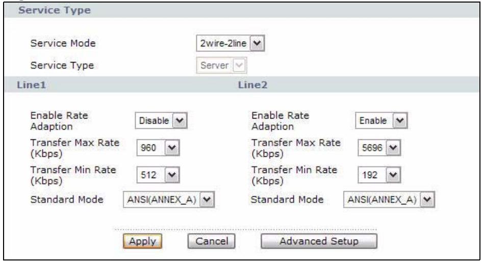
Figure 29 2wire-2line Service Mode
The following table describes the labels in this screen.
Table 13 2wire-2line Service Mode
| LABEL | DESCRIPTION |
| Service Type | |
| Service Mode | Select 2wire-2line mode for the DSL connection. This means that the P-793H v2 is going to be a server connected to two client P-793H v2s. |
| Service Type | When you select 2wire-2line mode this field automatically changes to Server. |
| Line1 / Line 2 | You can configure different connection rate settings for Line 1 and Line 2 DSL connections. |
| Enable Rate Adaption | Indicate whether or not the P-793H v2 can adjust the speed of its connection to that of the other device. |
| Transfer Max Rate (Kbps) | This field is enabled if Service Type is Server. Set the maximum rate at which the P-793H v2 sends and receives information. The actual transfer rate will be between this value and the minimum transfer rate you configure. |
| Transfer Min Rate (Kbps) | This field is enabled if Service Type is Server. Set the minimum rate at which the P-793H v2 sends and receives information. The actual transfer rate will be between this value and the maximum transfer rate you configure. |
| Standard Mode | Select the operational mode the P-793H v2 uses in the DSL connection. Annex A refers to connections over POTS and Annex B refers to connections over ISDN lines. |
| Apply | Click Apply to save the changes. |
| Cancel | Click Cancel to begin configuring this screen afresh. |
| Advanced Setup | Click this button to display the Advanced WAN Setup screen and edit more details of your WAN setup. |
6.2.2 Advanced Internet Access Setup
Use this screen to edit your P-793H v2's advanced WAN settings. Click the Advanced Setup button in the Internet Access Setup screen. The screen appears as shown.
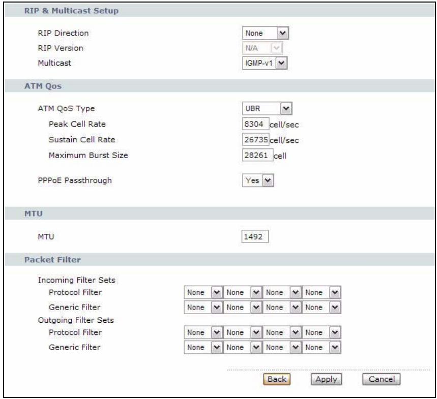
Figure 30 Network > WAN > Internet Access Setup: Advanced Setup
The following table describes the labels in this screen.
Table 14 Network > WAN > Internet Access Setup: Advanced Setup
| LABEL | DESCRIPTION |
| RIP & Multicast Setup | This section is not available when you configure the P-793H v2 to be in bridge mode. |
| RIP Direction | RIP (Routing Information Protocol) allows a router to exchange routing information with other routers. Use this field to control how much routing information the P-793H v2 sends and receives on the subnet. Select the RIP direction from None, Both, In Only and Out Only. |
| RIP Version | This field is not configurable if you select None in the RIP Direction field. Select the RIP version from RIP-1, RIP-2B and RIP-2M. |
| Multicast | Multicast packets are sent to a group of computers on the LAN and are an alternative to unicast packets (packets sent to one computer) and broadcast packets (packets sent to every computer). Internet Group Multicast Protocol (IGMP) is a network-layer protocol used to establish membership in a multicast group. The P-793H v2 supports IGMP-v1, IGMP-v2 and IGMP-v3. Select None to disable it. |
| ATM QoS | |
| ATM QoS Type | Select CBR (Continuous Bit Rate) to specify fixed (always-on) bandwidth for voice or data traffic. Select UBR (Unspecified Bit Rate) for applications that are non-time sensitive, such as e-mail. Select VBR-RT (real-time Variable Bit Rate) type for applications with bursty connections that require closely controlled delay and delay variation. Select VBR-nRT (non real-time Variable Bit Rate) type for connections that do not require closely controlled delay and delay variation. |
| Peak Cell Rate | Divide the DSL line rate (bps) by 424 (the size of an ATM cell) to find the Peak Cell Rate (PCR). This is the maximum rate at which the sender can send cells. Type the PCR here. |
| Sustain Cell Rate | The Sustain Cell Rate (SCR) sets the average cell rate (long-term) that can be transmitted. Type the SCR, which must be less than the PCR. Note that system default is 0 cells/sec. |
| Maximum Burst Size | Maximum Burst Size (MBS) refers to the maximum number of cells that can be sent at the peak rate. Type the MBS, which is less than 65535. |
| PPPoE Passthrough (PPPoE encapsulation only) | This field is available when you select PPPoE encapsulation. In addition to the P-793H v2's built-in PPPoE client, you can enable PPPoE pass through to allow up to ten hosts on the LAN to use PPPoE client software on their computers to connect to the ISP via the P-793H v2. Each host can have a separate account and a public WAN IP address. PPPoE pass through is an alternative to NAT for application where NAT is not appropriate. Disable PPPoE pass through if you do not need to allow hosts on the LAN to use PPPoE client software on their computers to connect to the ISP. |
| MTU | |
| MTU | The Maximum Transmission Unit (MTU) defines the size of the largest packet allowed on an interface or connection. Enter the MTU in this field.For ENET ENCAP, the MTU value is 1500.For PPPoE, the MTU value is 1492.For PPPoA and RFC 1483, the MTU is 65535. |
| Packet Filter | |
| Incoming Filter Sets | |
| Protocol Filter | Select the protocol filter(s) to control incoming traffic. You may choose up to 4 sets of filters.You can configure packet filters in the Packet Filter screen. See Chapter 12 on page 217 for more details. |
| Generic Filter | Select the generic filter(s) to control incoming traffic. You may choose up to 4 sets of filters.You can configure generic filters in the Packet Filter screen. See Chapter 12 on page 217 for more details. |
| Outgoing Filter Sets | |
| Protocol Filter | Select the protocol filter(s) to control outgoing traffic. You may choose up to 4 sets of filters.You can configure protocol filters in the Packet Filter screen. See Chapter 12 on page 217 for more details. |
| Generic Filter | Select the generic filter(s) to control outgoing traffic. You may choose up to 4 sets of filters.You can configure generic filters in the Packet Filter screen. See Chapter 12 on page 217 for more details. |
| Back | Click this to return to the previous screen without saving. |
| Apply | Click this to save your changes. |
| Cancel | Click this to restore your previously saved settings. |
6.3 The More Connections Screen
The P-793H v2 allows you to configure more than one Internet access connection. To configure additional Internet access connections click Network > WAN > More Connections. The screen differs by the encapsulation you select. When you use the WAN > Internet Access Setup screen to set up Internet access, you are configuring the first WAN connection.
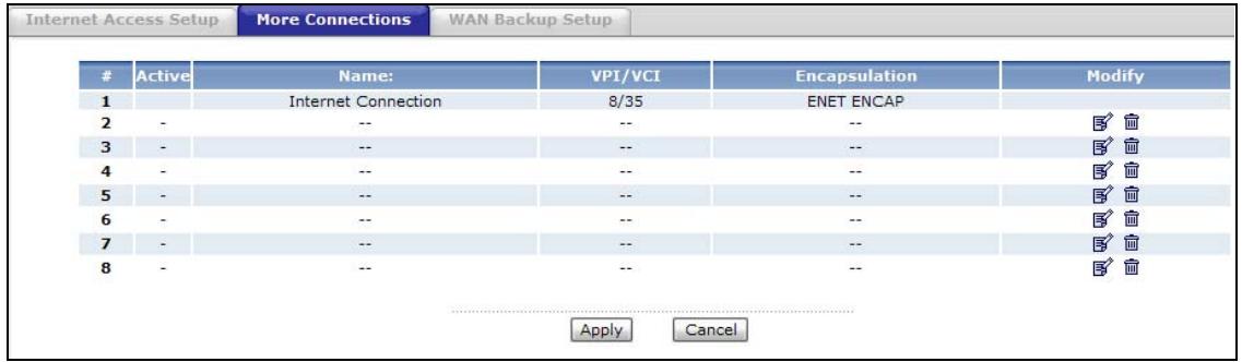
Figure 31 Network > WAN > More Connections
The following table describes the labels in this screen.
Table 15 Network > WAN > More Connections
| LABEL | DESCRIPTION |
| # | This is an index number indicating the number of the corresponding connection. |
| Active | This field indicates whether the connection is active or not. |
| Name | This is the name you gave to the Internet connection. |
| VPI/VCI | This field displays the Virtual Path Identifier (VPI) and Virtual Channel Identifier (VCI) numbers configured for this WAN connection. |
| Encapsulation | This field indicates the encapsulation method of the Internet connection. |
| Modify | The first (ISP) connection is read-only in this screen. Use the WAN > Internet Access Setup screen to edit it. Click the Edit icon to edit the Internet connection settings. Click this icon on an empty configuration to add a new Internet access setup. Click the Remove icon to delete the Internet access setup from your connection list. |
| Apply | Click this to save your changes. |
| Cancel | Click this to restore your previously saved settings. |
6.3.1 More Connections Edit
Use this screen to configure a connection. Click the edit icon in the More Connections screen to display the following screen.
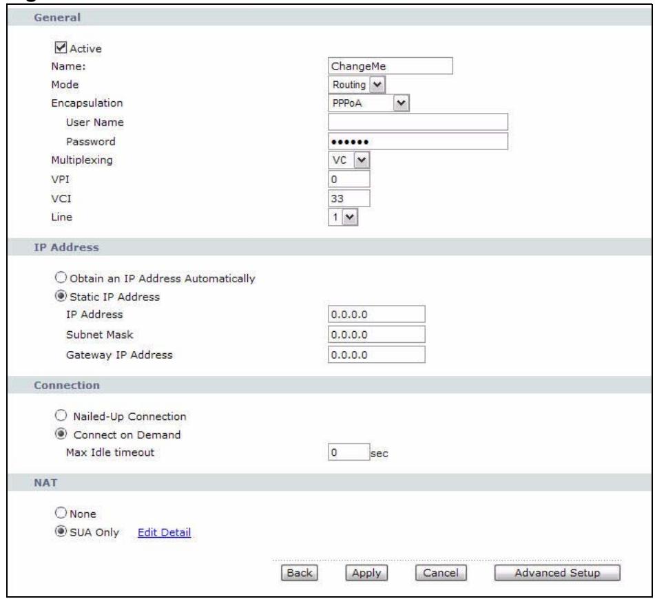
Figure 32 Network > WAN > More Connections: Edit
The following table describes the labels in this screen.
Table 16 Network > WAN > More Connections: Edit
| LABEL | DESCRIPTION |
| General | |
| Active | Select the check box to activate or clear the check box to deactivate this connection. |
| Name | Enter a unique, descriptive name of up to 13 ASCII characters for this connection. |
| Mode | Select Routing from the drop-down list box if your ISP allows multiple computers to share an Internet account. If you select Bridge, the P-793H v2 will forward any packet that it does not route to this remote node; otherwise, the packets are discarded. |
| Encapsulation | Select the method of encapsulation used by your ISP from the drop-down list box. Choices vary depending on the mode you select in the Mode field. If you select Bridge in the Mode field, select either PPPoA or RFC 1483. If you select Routing in the Mode field, select PPPoA, RFC 1483, ENET ENCAP or PPPoE. If you set up a point-to-point connection, select either ENET ENCAP or RFC 1483. |
| User Name | (PPPoA and PPPoE encapsulation only) Enter the user name exactly as your ISP assigned. If assigned a name in the form user@domain where domain identifies a service name, then enter both components exactly as given. |
| Password | (PPPoA and PPPoE encapsulation only) Enter the password associated with the user name above. |
| Service Name | (PPPoE only) Type the name of your PPPoE service here. |
| Multiplexing | Select the method of multiplexing used by your ISP from the drop-down list. Choices are VC or LLC. By prior agreement, a protocol is assigned a specific virtual circuit, for example, VC1 will carry IP. If you select VC, specify separate VPI and VCI numbers for each protocol. For LLC-based multiplexing or PPP encapsulation, one VC carries multiple protocols with protocol identifying information being contained in each packet header. In this case, only one set of VPI and VCI numbers need be specified for all protocols. |
| VPI | The valid range for the VPI is 0 to 255. Enter the VPI assigned to you. |
| VCI | The valid range for the VCI is 32 to 65535 (0 to 31 is reserved for local management of ATM traffic). Enter the VCI assigned to you. |
| Line | Select the DSL line you want the P-793H v2 to use as a default for outgoing traffic (remote node 1). |
| IP Address | This option is available if you select Routing in the Mode field. A static IP address is a fixed IP that your ISP gives you. A dynamic IP address is not fixed; the ISP assigns you a different one each time you connect to the Internet. If you use the encapsulation type except RFC 1483, select Obtain an IP Address Automatically when you have a dynamic IP address; otherwise select Static IP Address and type your ISP assigned IP address in the IP Address field below. If you use RFC 1483, enter the IP address given by your ISP in the IP Address field. |
| Subnet Mask | Enter a subnet mask in dotted decimal notation. |
| Gateway IP address | Specify a gateway IP address (supplied by your ISP). |
| Connection | |
| Nailed-Up Connection | Select Nailed-Up Connection when you want your connection up all the time. The P-793H v2 will try to bring up the connection automatically if it is disconnected. |
| Connect on Demand | Select Connect on Demand when you don't want the connection up all the time and specify an idle time-out in the Max Idle Timeout field. |
| Max Idle Timeout | Specify an idle time-out in the Max Idle Timeout field when you select Connect on Demand. The default setting is 0, which means the Internet session will not timeout. |
| NAT | SUA only is available only when you select Routing in the Mode field. Select SUA Only if you have one public IP address and want to use NAT. Click Edit Detail to go to the Port Forwarding screen to edit a server mapping set. Otherwise, select None to disable NAT. |
| Back | Click this to return to the previous screen without saving. |
| Apply | Click this to save your changes. |
| Cancel | Click this to restore your previously saved settings. |
| Advanced Setup | Click this to display the More Connections Advanced Setup screen and edit more details of your WAN setup. |
6.3.2 Configuring More Connections Advanced Setup
Use this screen to edit your P-793H v2's advanced WAN settings. Click the Advanced Setup button in the More Connections Edit screen. The screen appears as shown.

Figure 33 Network > WAN > More Connections: Edit: Advanced Setup
The following table describes the labels in this screen.
Table 17 Network > WAN > More Connections: Edit: Advanced Setup
| LABEL | DESCRIPTION |
| RIP & Multicast Setup | This section is not available when you configure the P-793H v2 to be in bridge mode. |
| RIP Direction | Select the RIP direction from None, Both, In Only and Out Only. |
| RIP Version | Select the RIP version from RIP-1, RIP-2B and RIP-2M. |
| Multicast | IGMP (Internet Group Multicast Protocol) is a network-layer protocol used to establish membership in a multicast group. The P-793H v2 supports IGMP-v1, IGMP-v2 and IGMP-v3. Select None to disable it. |
| ATM QoS | |
| ATM QoS Type | Select CBR (Continuous Bit Rate) to specify fixed (always-on) bandwidth for voice or data traffic. Select UBR (Unspecified Bit Rate) for applications that are non-time sensitive, such as e-mail. Select VBR-nRT (Variable Bit Rate-non Real Time) or VBR-RT (Variable Bit Rate-Real Time) for bursty traffic and bandwidth sharing with other applications. |
| Peak Cell Rate | Divide the DSL line rate (bps) by 424 (the size of an ATM cell) to find the Peak Cell Rate (PCR). This is the maximum rate at which the sender can send cells. Type the PCR here. |
| Sustain Cell Rate | The Sustain Cell Rate (SCR) sets the average cell rate (long-term) that can be transmitted. Type the SCR, which must be less than the PCR. Note that system default is 0 cells/sec. |
| Maximum Burst Size | Maximum Burst Size (MBS) refers to the maximum number of cells that can be sent at the peak rate. Type the MBS, which is less than 65535. |
| MTU | |
| MTU | The Maximum Transmission Unit (MTU) defines the size of the largest packet allowed on an interface or connection. Enter the MTU in this field. For ENET ENCAP, the MTU value is 1500. For PPPoE, the MTU value is 1492. For PPPoA and RFC, the MTU is 65535. |
| Packet Filter | |
| Incoming Filter Sets | |
| Protocol Filter | Select the protocol filter(s) to control incoming traffic. You may choose up to 4 sets of filters. You can configure packet filters in the Packet Filter screen. See Chapter 12 on page 217 for more details. |
| Generic Filter | Select the generic filter(s) to control incoming traffic. You may choose up to 4 sets of filters. You can configure generic filters in the Packet Filter screen. See Chapter 12 on page 217 for more details. |
| Outgoing Filter Sets | |
| Protocol Filter | Select the protocol filter(s) to control outgoing traffic. You may choose up to 4 sets of filters. You can configure protocol filters in the Packet Filter screen. See Chapter 12 on page 217 for more details. |
| Generic Filter | Select the generic filter(s) to control outgoing traffic. You may choose up to 4 sets of filters. You can configure generic filters in the Packet Filter screen. See Chapter 12 on page 217 for more details. |
| Back | Click this to return to the previous screen without saving. |
| Apply | Click this to save your changes. |
| Cancel | Click this to restore your previously saved settings. |
6.4 The WAN Backup Setup Screen
Use this screen to configure your P-793H v2's WAN backup. Click Network > WAN > WAN Backup Setup. This screen is not available if you set the WAN type to Ethernet in the Internet Access Setup screen.
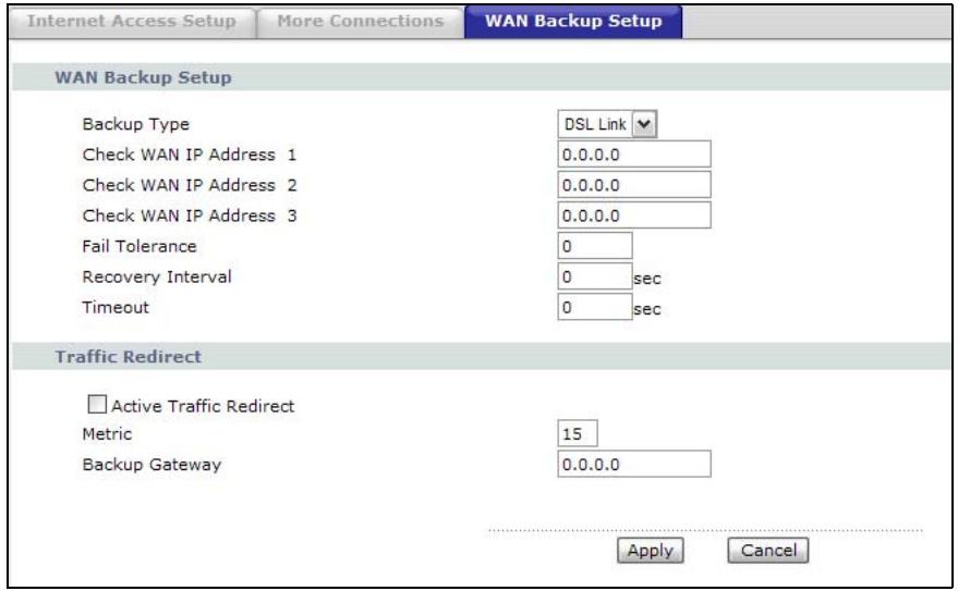
Figure 34 Network > Internet (WAN) > WAN Backup
The following table describes the labels in this screen.
Table 18 Network > Internet (WAN) > WAN Backup
| LABEL | DESCRIPTION |
| Backup Type | Select the method that the P-793H v2 uses to check the DSL connection. |
| Select DSL Link to have the P-793H v2 check if the connection to the DSLAM is up. Select ICMP to have the P-793H v2 periodically ping the IP addresses configured in the Check WAN IP Address fields. | |
| Check WAN IP Address1-3 | Configure this field to test your P-793H v2's WAN accessibility. Type the IP address of a reliable nearby computer (for example, your ISP's DNS server address). |
| If you activate either traffic redirect or dial backup, you must configure at least one IP address here. | |
| When using a WAN backup connection, the P-793H v2 periodically pings the addresses configured here and uses the other WAN backup connection (if configured) if there is no response. | |
| Fail Tolerance | Type the number of times (2 recommended) that your P-793H v2 may ping the IP addresses configured in the Check WAN IP Address field without getting a response before switching to a WAN backup connection (or a different WAN backup connection). |
Table 18 Network > Internet (WAN) > WAN Backup
| LABEL | DESCRIPTION |
| Recovery Interval | When the P-793H v2 is using a lower priority connection (usually a WAN backup connection), it periodically checks whether or not it can use a higher priority connection.Type the number of seconds (30 recommended) for the P-793H v2 to wait between checks. Allow more time if your destination IP address handles lots of traffic. |
| Timeout | Type the number of seconds (3 recommended) for your P-793H v2 to wait for a ping response from one of the IP addresses in the Check WAN IP Address field before timing out the request. The WAN connection is considered "down" after the P-793H v2 times out the number of times specified in the Fail Tolerance field. Use a higher value in this field if your network is busy or congested. |
| Traffic Redirect | Traffic redirect forwards traffic to a backup gateway when the P-793H v2 cannot connect to the Internet. |
| Active Traffic Redirect | Select this check box to have the P-793H v2 use traffic redirect if the normal WAN connection goes down.Note: If you activate traffic redirect, you must configure at least one Check WAN IP Address. |
| Metric | This field sets this route's priority among the routes the P-793H v2 uses.The metric represents the "cost of transmission". A router determines the best route for transmission by choosing a path with the lowest "cost". RIP routing uses hop count as the measurement of cost, with a minimum of "1" for directly connected networks. The number must be between "1" and "15"; a number greater than "15" means the link is down. The smaller the number, the lower the "cost". |
| Backup Gateway | Type the IP address of your backup gateway in dotted decimal notation. The P-793H v2 automatically forwards traffic to this IP address if the P-793H v2's Internet connection terminates. |
| Apply | Click Apply to save the changes. |
| Cancel | Click Cancel to begin configuring this screen afresh. |
6.5 WAN Technical Reference
This section provides some technical background information about the topics covered in this chapter.
6.5.1 Encapsulation
Be sure to use the encapsulation method required by your ISP. The P-793H v2 supports the following methods.
6.5.1.1 ENETENCAP
The MAC Encapsulated Routing Link Protocol (ENET ENCAP) is only implemented with the IP network protocol. IP packets are routed between the Ethernet interface and the WAN interface and then formatted so that they can be understood in a bridged environment. For instance, it encapsulates routed Ethernet frames into bridged ATM cells. ENET ENCAP requires that you specify a gateway IP address in the Gateway IP Address field in the wizard or WAN screen. You can get this information from your ISP.
6.5.1.2 PPP over Ethernet
The P-793H v2 supports PPPoE (Point-to-Point Protocol over Ethernet). PPPoE is an IETF Draft standard (RFC 2516) specifying how a personal computer (PC) interacts with a broadband modem (DSL, cable, wireless, etc.) connection. The PPPoE option is for a dial-up connection using PPPoE.
For the service provider, PPPoE offers an access and authentication method that works with existing access control systems (for example RADIUS).
One of the benefits of PPPoE is the ability to let you access one of multiple network services, a function known as dynamic service selection. This enables the service provider to easily create and offer new IP services for individuals.
Operationally, PPPoE saves significant effort for both you and the ISP or carrier, as it requires no specific configuration of the broadband modem at the customer site.
By implementing PPPoE directly on the P-793H v2 (rather than individual computers), the computers on the LAN do not need PPPoE software installed, since the P-793H v2 does that part of the task. Furthermore, with NAT, all of the LANs' computers will have access.
6.5.1.3 PPPoA
PPPoA stands for Point to Point Protocol over ATM Adaptation Layer 5 (AAL5). A PPPoA connection functions like a dial-up Internet connection. The P-793H v2 encapsulates the PPP session based on RFC1483 and sends it through an ATM PVC (Permanent Virtual Circuit) to the Internet Service Provider's (ISP) DSLAM (Digital Subscriber Line (DSL) Access Multiplexer). Please refer to RFC 2364 for more information on PPPoA. Refer to RFC 1661 for more information on PPP.
6.5.1.4 RFC 1483
RFC 1483 describes two methods for Multiprotocol Encapsulation over ATM Adaptation Layer 5 (AAL5). The first method allows multiplexing of multiple protocols over a single ATM virtual circuit (LLC-based multiplexing) and the second
method assumes that each protocol is carried over a separate ATM virtual circuit (VC-based multiplexing). Please refer to RFC 1483 for more detailed information.
6.5.2 Multiplexing
There are two conventions to identify what protocols the virtual circuit (VC) is carrying. Be sure to use the multiplexing method required by your ISP.
VC-based Multiplexing
In this case, by prior mutual agreement, each protocol is assigned to a specific virtual circuit; for example, VC1 carries IP, etc. VC-based multiplexing may be dominant in environments where dynamic creation of large numbers of ATM VCs is fast and economical.
LLC-based Multiplexing
In this case one VC carries multiple protocols with protocol identifying information being contained in each packet header. Despite the extra bandwidth and processing overhead, this method may be advantageous if it is not practical to have a separate VC for each carried protocol, for example, if charging heavily depends on the number of simultaneous VCs.
6.5.3 VPI and VCI
Be sure to use the correct Virtual Path Identifier (VPI) and Virtual Channel Identifier (VCI) numbers assigned to you. The valid range for the VPI is 0 to 255 and for the VCI is 32 to 65535 (0 to 31 is reserved for local management of ATM traffic). Please see the appendix for more information.
6.5.4 IP Address Assignment
A static IP is a fixed IP that your ISP gives you. A dynamic IP is not fixed; the ISP assigns you a different one each time. The Single User Account feature can be enabled or disabled if you have either a dynamic or static IP. However the encapsulation method assigned influences your choices for IP address and ENET EncAP gateway.
IP Assignment with PPPoA or PPPoE Encapsulation
If you have a dynamic IP, then the IP Address and Gateway IP Address fields are not applicable (N/A). If you have a static IP, then you only need to fill in the IP Address field and not the Gateway IP Address field.
IP Assignment with RFC 1483 Encapsulation
In this case the IP address assignment must be static.
IP Assignment with ENET EncAP Encapsulation
In this case you can have either a static or dynamic IP. For a static IP you must fill in all the IP Address and Gateway IP Address fields as supplied by your ISP. However for a dynamic IP, the P-793H v2 acts as a DHCP client on the WAN port and so the IP Address and Gateway IP Address fields are not applicable (N/A) as the DHCP server assigns them to the P-793H v2.
6.5.5 Nailed-Up Connection (PPP)
A nailed-up connection is a dial-up line where the connection is always up regardless of traffic demand. The P-793H v2 does two things when you specify a nailed-up connection. The first is that idle timeout is disabled. The second is that the P-793H v2 will try to bring up the connection when turned on and whenever the connection is down. A nailed-up connection can be very expensive for obvious reasons.
Do not specify a nailed-up connection unless your telephone company offers flat-rate service or you need a constant connection and the cost is of no concern.
6.5.6 NAT
NAT (Network Address Translation - NAT, RFC 1631) is the translation of the IP address of a host in a packet, for example, the source address of an outgoing packet, used within one network to a different IP address known within another network.
6.6 Metric
The metric represents the "cost of transmission". A router determines the best route for transmission by choosing a path with the lowest "cost". RIP routing uses hop count as the measurement of cost, with a minimum of "1" for directly connected networks. The number must be between "1" and "15"; a number greater than "15" means the link is down. The smaller the number, the lower the "cost".
The metric sets the priority for the P-793H v2's routes to the Internet. If any two of the default routes have the same metric, the P-793H v2 uses the following predefined priorities:
- Normal route: designated by the ISP (see Section 6.2 on page 78)
Traffic-redirect route (see Section 6.7 on page 97)
For example, if the normal route has a of "1" and the traffic-direct route has a metric of "2", then the normal route acts as the primary default route. If the normal route fails to connect to the Internet, the P-793H v2 tries the traffic-direct route next.
If you want the traffic-redirect route route to take priority over the normal route, all you need to do is set the traffic-redirect route's metric to "1" and the normal route to "2".
IP Policy Routing overrides the default routing behavior and takes priority over all of the routes mentioned above.
6.7 Traffic Redirect
Traffic redirect forwards traffic to a backup gateway when the P-793H v2 cannot connect to the Internet. An example is shown in the figure below.
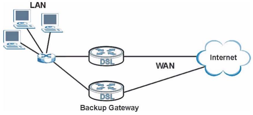
Figure 35 Traffic Redirect Example
The following network topology allows you to avoid triangle route security issues when the backup gateway is connected to the LAN. Use IP alias to configure the LAN into two or three logical networks with the P-793H v2 itself as the gateway for each LAN network. Put the protected LAN in one subnet (Subnet 1 in the following figure) and the backup gateway in another subnet (Subnet 2). Configure filters
that allow packets from the protected LAN (Subnet 1) to the backup gateway (Subnet 2).
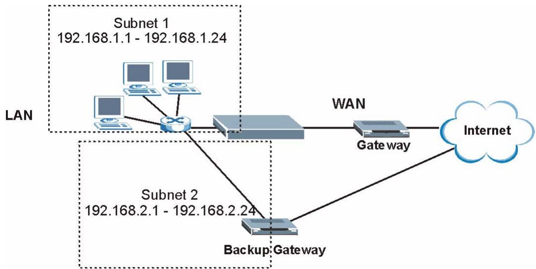
Figure 36 Traffic Redirect LAN Setup
6.8 Traffic Shaping
Traffic Shaping is an agreement between the carrier and the subscriber to regulate the average rate and fluctuations of data transmission over an ATM network. This agreement helps eliminate congestion, which is important for transmission of real time data such as audio and video connections.
Peak Cell Rate (PCR) is the maximum rate at which the sender can send cells. This parameter may be lower (but not higher) than the maximum line speed. 1 ATM cell is 53 bytes (424 bits), so a maximum speed of 832Kbps gives a maximum PCR of 1962 cells/sec. This rate is not guaranteed because it is dependent on the line speed.
Sustained Cell Rate (SCR) is the mean cell rate of each bursty traffic source. It specifies the maximum average rate at which cells can be sent over the virtual connection. SCR may not be greater than the PCR.
Maximum Burst Size (MBS) is the maximum number of cells that can be sent at the PCR. After MBS is reached, cell rates fall below SCR until cell rate averages to the SCR again. At this time, more cells (up to the MBS) can be sent at the PCR again.
If the PCR, SCR or MBS is set to the default of "0", the system will assign a maximum value that correlates to your upstream line rate.
The following figure illustrates the relationship between PCR, SCR and MBS.
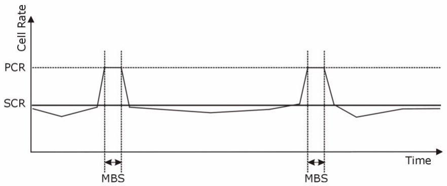
Figure 37 Example of Traffic Shaping
6.8.1 ATM Traffic Classes
These are the basic ATM traffic classes defined by the ATM Forum Traffic Management 4.0 Specification.
Constant Bit Rate (CBR)
Constant Bit Rate (CBR) provides fixed bandwidth that is always available even if no data is being sent. CBR traffic is generally time-sensitive (doesn't tolerate delay). CBR is used for connections that continuously require a specific amount of bandwidth. A PCR is specified and if traffic exceeds this rate, cells may be dropped. Examples of connections that need CBR would be high-resolution video and voice.
Variable Bit Rate (VBR)
The Variable Bit Rate (VBR) ATM traffic class is used with bursty connections. Connections that use the Variable Bit Rate (VBR) traffic class can be grouped into real time (VBR-RT) or non-real time (VBR-nRT) connections.
The VBR-RT (real-time Variable Bit Rate) type is used with bursty connections that require closely controlled delay and delay variation. It also provides a fixed amount of bandwidth (a PCR is specified) but is only available when data is being sent. An example of an VBR-RT connection would be video conferencing. Video conferencing requires real-time data transfers and the bandwidth requirement varies in proportion to the video image's changing dynamics.
The VBR-nRT (non real-time Variable Bit Rate) type is used with bursty connections that do not require closely controlled delay and delay variation. It is commonly used for "bursty" traffic typical on LANs. PCR and MBS define the burst
levels, SCR defines the minimum level. An example of an VBR-nRT connection would be non-time sensitive data file transfers.
Unspecified Bit Rate (UBR)
The Unspecified Bit Rate (UBR) ATM traffic class is for bursty data transfers. However, UBR doesn't guarantee any bandwidth and only delivers traffic when the network has spare bandwidth. An example application is background file transfer.
LAN Setup
7.1 Overview
A Local Area Network (LAN) is a shared communication system to which many networking devices are connected. It is usually located in one immediate area such as a building or floor of a building.
Use the LAN screens to help you configure a LAN DHCP server and manage IP addresses.
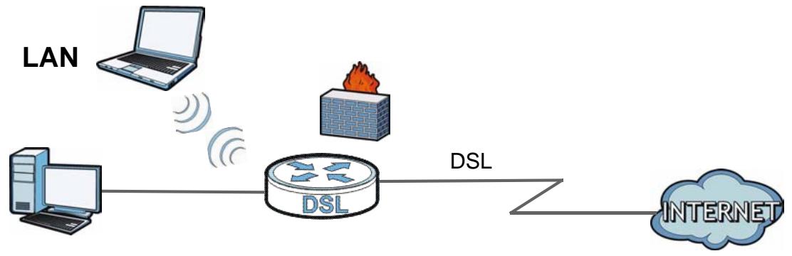
7.1.1 What You Can Do in the LAN Screens
- Use the IP screen (Section 7.2 on page 103) to set the LAN IP address and subnet mask of your ZyXEL device. You can also edit your P-793H v2's RIP, multicast, any IP and Windows Networking settings from this screen.
- Use the DHCP Setup screen (Section 7.3 on page 106) to configure the ZyXEL Device's DHCP settings.
- Use the Client List screen (Section 7.4 on page 108) to assign IP addresses on the LAN to specific individual computers based on their MAC Addresses.
- Use the IP Alias screen (Section 7.5 on page 109) to change your P-793H v2's IP alias settings.
7.1.2 What You Need To Know About LAN
IP Address
IP addresses identify individual devices on a network. Every networking device (including computers, servers, routers, printers, etc.) needs an IP address to communicate across the network. These networking devices are also known as hosts.
Subnet Mask
Subnet masks determine the maximum number of possible hosts on a network. You can also use subnet masks to divide one network into multiple sub-networks.
DHCP
A DHCP (Dynamic Host Configuration Protocol) server can assign your P-793H v2 an IP address, subnet mask, DNS and other routing information when it's turned on.
RIP
RIP (Routing Information Protocol) allows a router to exchange routing information with other routers.
Multicast
Traditionally, IP packets are transmitted in one of either two ways - Unicast (1 sender - 1 recipient) or Broadcast (1 sender - everybody on the network). Multicast delivers IP packets to a group of hosts on the network - not everybody and not just 1.
IGMP
IGMP (Internet Group Multicast Protocol) is a network-layer protocol used to establish membership in a Multicast group - it is not used to carry user data. There are three versions of IGMP. IGMP version 2 and 3 are improvements over version 1, but IGMP version 1 is still in wide use.
DNS
DNS (Domain Name System) is for mapping a domain name to its corresponding IP address and vice versa. The DNS server is extremely important because without it, you must know the IP address of a networking device before you can access it.
Finding Out More
See Section 7.6 on page 111 for technical background information on LANs.
7.1.3 Before You Begin
Find out the MAC addresses of your network devices if you intend to add them to the DHCP Client List screen.
7.2 The IP Screen
Use this screen to set the Local Area Network IP address and subnet mask of your P-793H v2. Click Network > LAN to open the IP screen.
Follow these steps to configure your LAN settings.
1 Enter an IP address into the IP Address field. The IP address must be in dotted decimal notation. This will become the IP address of your P-793H v2.
2 Enter the IP subnet mask into the IP Subnet Mask field. Unless instructed otherwise it is best to leave this alone, the configurator will automatically compute a subnet mask based upon the IP address you entered.
3 Click Apply to save your settings.
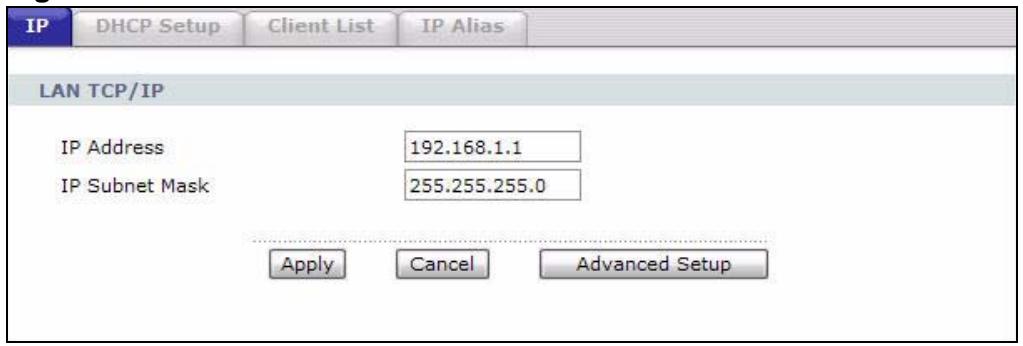
Figure 38 Network > LAN > IP
The following table describes the fields in this screen.
Table 19 Network > LAN > IP
| LABEL | DESCRIPTION |
| IP Address | Enter the LAN IP address you want to assign to your P-793H v2 in dotted decimal notation, for example, 192.168.1.1 (factory default). |
| IP Subnet Mask | Type the subnet mask of your network in dotted decimal notation, for example 255.255.255.0 (factory default). Your P-793H v2 automatically computes the subnet mask based on the IP Address you enter, so do not change this field unless you are instructed to do so. |
| Apply | Click this to save your changes. |
| Cancel | Click this to restore your previously saved settings. |
| Advanced Setup | Click this to display the Advanced LAN Setup screen and edit more details of your LAN setup. |
7.2.1 The Advanced LAN IP Setup Screen
Use this screen to edit your P-793H v2's RIP, multicast, Any IP and Windows Networking settings. Click the Advanced Setup button in the LAN IP screen. The screen appears as shown.
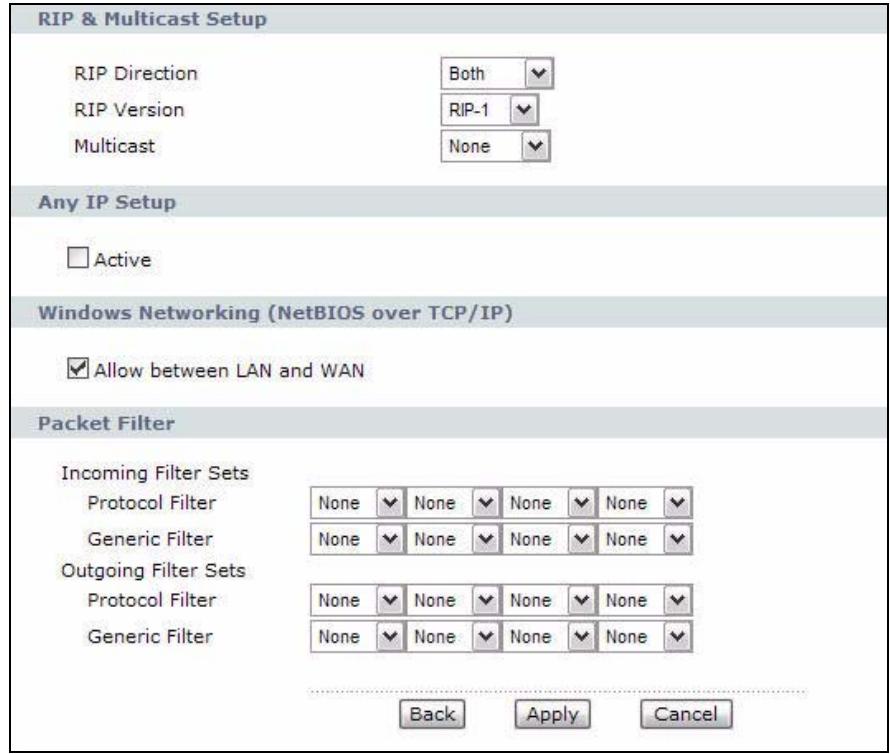
Figure 39 Network > LAN > IP: Advanced Setup
The following table describes the labels in this screen.
Table 20 Network > LAN > IP: Advanced Setup
| LABEL | DESCRIPTION |
| RIP & Multicast Setup | |
| RIP Direction | Select the RIP direction from None, Both, In Only and Out Only. |
| RIP Version | Select the RIP version from RIP-1, RIP-2B and RIP-2M. |
| Multicast | IGMP (Internet Group Multicast Protocol) is a network-layer protocol used to establish membership in a multicast group. The P-793H v2 supports IGMP-v1, IGMP-v2 and IGMP-v3. Select None to disable it. |
| Any IP Setup | |
| Active | Select the Active check box to enable the Any IP feature. This allows a computer to access the Internet via the P-793H v2 without changing the network settings (such as IP address and subnet mask) of the computer, even when the IP addresses of the computer and the P-793H v2 are not in the same subnet.When you disable the Any IP feature, only computers with dynamic IP addresses or static IP addresses in the same subnet as the P-793H v2's LAN IP address can connect to the P-793H v2 or access the Internet through the P-793H v2.Note: You must enable NAT/SUA in the NAT screen to use the Any IP feature on the P-793H v2 |
| Windows Networking (NetBIOS over TCP/IP) | NetBIOS (Network Basic Input/Output System) are TCP or UDP packets that enable a computer to connect to and communicate with a LAN. For some dial-up services such as PPPoE or PPTP, NetBIOS packets cause unwanted calls. However it may sometimes be necessary to allow NetBIOS packets to pass through to the WAN in order to find a computer on the WAN. |
| Allow between LAN and WAN | Select this check box to forward NetBIOS packets from the LAN to the WAN and from the WAN to the LAN. If your firewall is enabled with the default policy set to block WAN to LAN traffic, you also need to enable the default WAN to LAN firewall rule that forwards NetBIOS traffic.Clear this check box to block all NetBIOS packets going from the LAN to the WAN and from the WAN to the LAN. |
| Packet Filter | |
| Incoming Filter Sets | |
| Protocol Filter | Select the protocol filter(s) to control incoming traffic. You may choose up to 4 sets of filters.You can configure packet filters in the Packet Filter screen. See Chapter 12 on page 217 for more details. |
| Generic Filter | Select the generic filter(s) to control incoming traffic. You may choose up to 4 sets of filters.You can configure generic filters in the Packet Filter screen. See Chapter 12 on page 217 for more details. |
Table 20 Network > LAN > IP: Advanced Setup
| LABEL | DESCRIPTION |
| Outgoing Filter Sets | |
| Protocol Filter | Select the protocol filter(s) to control outgoing traffic. You may choose up to 4 sets of filters.You can configure protocol filters in the Packet Filter screen. See Chapter 12 on page 217 for more details. |
| Generic Filter | Select the generic filter(s) to control outgoing traffic. You may choose up to 4 sets of filters.You can configure generic filters in the Packet Filter screen. See Chapter 12 on page 217 for more details. |
| Back | Click this to return to the previous screen without saving. |
| Apply | Click this to save your changes. |
| Cancel | Click this to restore your previously saved settings. |
7.3 The DHCP Setup Screen
Use this screen to configure the DNS server information that the P-793H v2 sends to the DHCP client devices on the LAN. Click Network > DHCP Setup to open this screen.
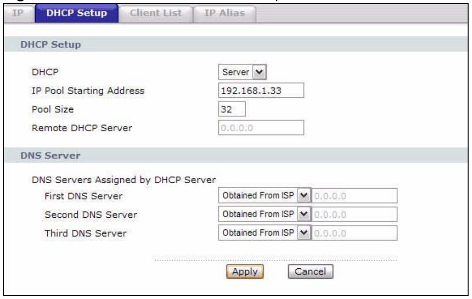
Figure 40 Network > LAN > DHCP Setup
The following table describes the labels in this screen.
Table 21 Network > LAN > DHCP Setup
| LABEL | DESCRIPTION |
| DHCP Setup | |
| DHCP | If set to Server, your P-793H v2 can assign IP addresses, an IP default gateway and DNS servers to Windows 95, Windows NT and other systems that support the DHCP client. If set to None, the DHCP server will be disabled. If set to Relay, the P-793H v2 acts as a surrogate DHCP server and relays DHCP requests and responses between the remote server and the clients. Enter the IP address of the actual, remote DHCP server in the Remote DHCP Server field in this case. When DHCP is used, the following items need to be set: |
| IP Pool Starting Address | This field specifies the first of the contiguous addresses in the IP address pool. |
| Pool Size | This field specifies the size, or count of the IP address pool. |
| Remote DHCP Server | If Relay is selected in the DHCP field above then enter the IP address of the actual remote DHCP server here. |
| DNS Server | |
| DNS Servers Assigned by DHCP Server | The P-793H v2 passes a DNS (Domain Name System) server IP address to the DHCP clients. |
| First DNS Server Second DNS Server Third DNS Server | Select Obtained From ISP if your ISP dynamically assigns DNS server information (and the P-793H v2's WAN IP address). Select UserDefined if you have the IP address of a DNS server. Enter the DNS server's IP address in the field to the right. If you chose UserDefined, but leave the IP address set to 0.0.0.0, UserDefined changes to None after you click Apply. If you set a second choice to UserDefined, and enter the same IP address, the second UserDefined changes to None after you click Apply. Select DNS Relay to have the P-793H v2 act as a DNS proxy only when the ISP uses IPCP DNS server extensions. The P-793H v2's LAN IP address displays in the field to the right (read-only). The P-793H v2 tells the DHCP clients on the LAN that the P-793H v2 itself is the DNS server. When a computer on the LAN sends a DNS query to the P-793H v2, the P-793H v2 forwards the query to the real DNS server learned through IPCP and relays the response back to the computer. You can only select DNS Relay for one of the three servers; if you select DNS Relay for a second or third DNS server, that choice changes to None after you click Apply. Select None if you do not want to configure DNS servers. You must have another DHCP sever on your LAN, or else the computers must have their DNS server addresses manually configured. If you do not configure a DNS server, you must know the IP address of a computer in order to access it. |
| Apply | Click this to save your changes. |
| Cancel | Click this to restore your previously saved settings. |
7.4 The Client List Screen
This table allows you to assign IP addresses on the LAN to specific individual computers based on their MAC Addresses.
Every Ethernet device has a unique MAC (Media Access Control) address. The MAC address is assigned at the factory and consists of six pairs of hexadecimal characters, for example, 00:A0:C5:00:00:02.
Use this screen to change your P-793H v2's static DHCP settings. Click Network > LAN > Client List to open the following screen.
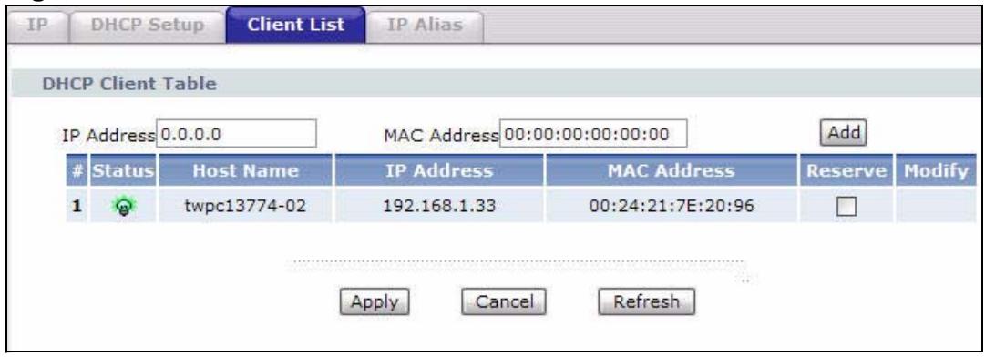
Figure 41 Network > LAN > Client List
The following table describes the labels in this screen.
Table 22 Network > LAN > Client List
| LABEL | DESCRIPTION |
| IP Address | Enter the IP address that you want to assign to the computer on your LAN with the MAC address that you will also specify. |
| MAC Address | Enter the MAC address of a computer on your LAN. |
| Add | Click this to add a static DHCP entry. |
| # | This is the index number of the static IP table entry (row). |
| Status | This field displays whether the client is connected to the P-793H v2. |
| Host Name | This field displays the computer host name. |
| IP Address | This field displays the IP address relative to the # field listed above. |
| MAC Address | The MAC (Media Access Control) or Ethernet address on a LAN (Local Area Network) is unique to your computer (six pairs of hexadecimal notation).A network interface card such as an Ethernet adapter has a hardwired address that is assigned at the factory. This address follows an industry standard that ensures no other adapter has a similar address. |
| Reserve | Select the check box in the heading row to automatically select all check boxes or select the check box(es) in each entry to have the P-793H v2 always assign the selected entry(ies)'s IP address(es) to the corresponding MAC address(es) (and host name(s)). You can select up to 10 entries in this table. |
Table 22 Network > LAN > Client List
| LABEL | DESCRIPTION |
| Modify | Click the modify icon to have the IP address field editable and change it. |
| Apply | Click this to save your changes. |
| Cancel | Click this to restore your previously saved settings. |
| Refresh | Click this to reload the DHCP table. |
7.5 The IP Alias Screen
IP alias allows you to partition a physical network into different logical networks over the same Ethernet interface. The P-793H v2 supports three logical LAN interfaces via its single physical Ethernet interface with the P-793H v2 itself as the gateway for each LAN network.
When you use IP alias, you can also configure firewall rules to control access between the LAN's logical networks (subnets).
Note: Make sure that the subnets of the logical networks do not overlap.
The following figure shows a LAN divided into subnets A, B, and C.
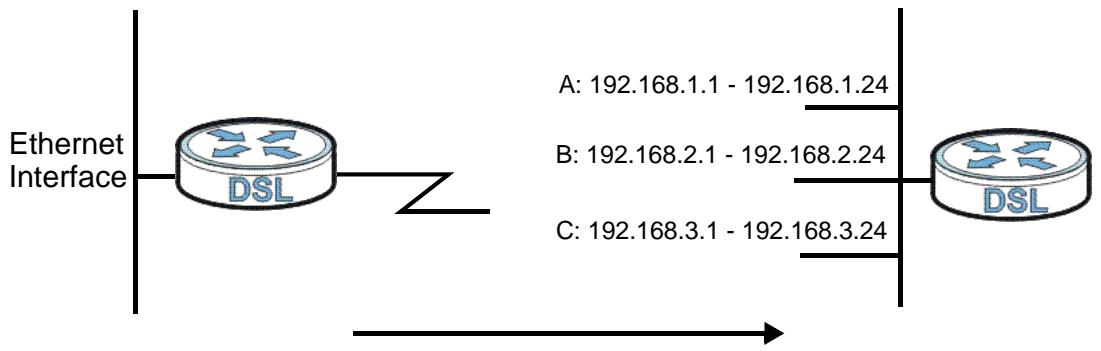
Figure 42 Physical Network & Partitioned Logical Networks
7.5.1 Configuring the LAN IP Alias Screen
Use this screen to change your P-793H v2's IP alias settings. Click Network > LAN > IP Alias to open the following screen.
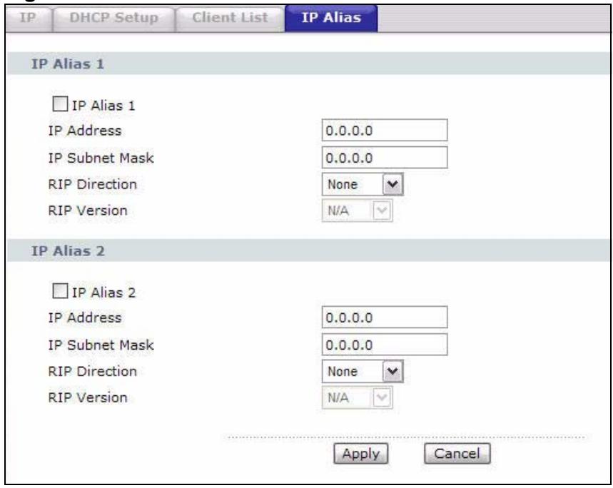
Figure 43 Network > LAN > IP Alias
The following table describes the labels in this screen.
Table 23 Network > LAN > IP Alias
| LABEL | DESCRIPTION |
| IP Alias 1, 2 | Select the check box to configure another LAN network for the P-793H v2. |
| IP Address | Enter the IP address of your P-793H v2 in dotted decimal notation. Alternatively, click the right mouse button to copy and/or paste the IP address. |
| IP Subnet Mask | Your P-793H v2 will automatically calculate the subnet mask based on the IP address that you assign. Unless you are implementing subnetting, use the subnet mask computed by the P-793H v2. |
| RIP Direction | RIP (Routing Information Protocol, RFC 1058 and RFC 1389) allows a router to exchange routing information with other routers. The RIP Direction field controls the sending and receiving of RIP packets. Select the RIP direction from Both/In Only/Out Only/None. When set to Both or Out Only, the P-793H v2 will broadcast its routing table periodically. When set to Both or In Only, it will incorporate the RIP information that it receives; when set to None, it will not send any RIP packets and will ignore any RIP packets received. |
Table 23 Network > LAN > IP Alias
| LABEL | DESCRIPTION |
| RIP Version | The RIP Version field controls the format and the broadcasting method of the RIP packets that the P-793H v2 sends (it recognizes both formats when receiving). RIP-1 is universally supported but RIP-2 carries more information. RIP-1 is probably adequate for most networks, unless you have an unusual network topology. Both RIP-2B and RIP-2M sends the routing data in RIP-2 format; the difference being that RIP-2B uses subnet broadcasting while RIP-2M uses multicast. Multicasting can reduce the load on non-router machines since they generally do not listen to the RIP multicast address and so will not receive the RIP packets. However, if one router uses multicast, then all routers on your network must use multicast, also. By default, RIP direction is set to Both and the Version set to RIP-1. |
| Apply | Click this to save your changes. |
| Cancel | Click this to restore your previously saved settings. |
7.6 LAN Technical Reference
This section provides some technical background information about the topics covered in this chapter.
7.6.1 LANs, WANs and the ZyXEL Device
The actual physical connection determines whether the P-793H v2 ports are LAN or WAN ports. There are two separate IP networks, one inside the LAN network and the other outside the WAN network as shown next.
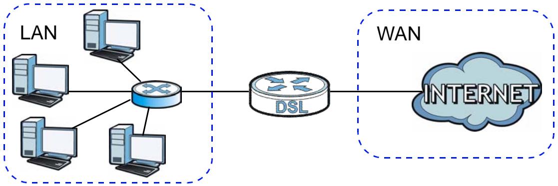
Figure 44 LAN and WAN IP Addresses
7.6.2 DHCP Setup
DHCP (Dynamic Host Configuration Protocol, RFC 2131 and RFC 2132) allows individual clients to obtain TCP/IP configuration at start-up from a server. You can configure the P-793H v2 as a DHCP server or disable it. When configured as a server, the P-793H v2 provides the TCP/IP configuration for the clients. If you turn DHCP service off, you must have another DHCP server on your LAN, or else the computer must be manually configured.
IP Pool Setup
The P-793H v2 is pre-configured with a pool of IP addresses for the DHCP clients (DHCP Pool). See the product specifications in the appendices. Do not assign static IP addresses from the DHCP pool to your LAN computers.
7.6.3 DNS Server Addresses
DNS (Domain Name System) maps a domain name to its corresponding IP address and vice versa. The DNS server is extremely important because without it, you must know the IP address of a computer before you can access it. The DNS server addresses you enter when you set up DHCP are passed to the client machines along with the assigned IP address and subnet mask.
There are two ways that an ISP disseminates the DNS server addresses.
- The ISP tells you the DNS server addresses, usually in the form of an information sheet, when you sign up. If your ISP gives you DNS server addresses, enter them in the DNS Server fields in the DHCP Setup screen.
- Some ISPs choose to disseminate the DNS server addresses using the DNS server extensions of IPCP (IP Control Protocol) after the connection is up. If your ISP did not give you explicit DNS servers, chances are the DNS servers are conveyed through IPCP negotiation. The P-793H v2 supports the IPCP DNS server extensions through the DNS proxy feature.
If the DNS Server fields in the DHCP Setup screen are set to DNS Relay, the P-793H v2 tells the DHCP clients that it itself is the DNS server. When a computer sends a DNS query to the P-793H v2, the P-793H v2 acts as a DNS proxy and forwards the query to the real DNS server learned through IPCP and relays the response back to the computer.
Please note that DNS proxy works only when the ISP uses the IPCP DNS server extensions. It does not mean you can leave the DNS servers out of the DHCP setup under all circumstances. If your ISP gives you explicit DNS servers, make sure that you enter their IP addresses in the DHCP Setup screen.
7.6.4 LAN TCP/IP
The P-793H v2 has built-in DHCP server capability that assigns IP addresses and DNS servers to systems that support DHCP client capability.
IP Address and Subnet Mask
Similar to the way houses on a street share a common street name, so too do computers on a LAN share one common network number.
Where you obtain your network number depends on your particular situation. If the ISP or your network administrator assigns you a block of registered IP addresses, follow their instructions in selecting the IP addresses and the subnet mask.
If the ISP did not explicitly give you an IP network number, then most likely you have a single user account and the ISP will assign you a dynamic IP address when the connection is established. If this is the case, it is recommended that you select a network number from 192.168.0.0 to 192.168.255.0 and you must enable the Network Address Translation (NAT) feature of the P-793H v2. The Internet Assigned Number Authority (IANA) reserved this block of addresses specifically for private use; please do not use any other number unless you are told otherwise. Let's say you select 192.168.1.0 as the network number; which covers 254 individual addresses, from 192.168.1.1 to 192.168.1.254 (zero and 255 are reserved). In other words, the first three numbers specify the network number while the last number identifies an individual computer on that network.
Once you have decided on the network number, pick an IP address that is easy to remember, for instance, 192.168.1.1, for your P-793H v2, but make sure that no other device on your network is using that IP address.
The subnet mask specifies the network number portion of an IP address. Your P-793H v2 will compute the subnet mask automatically based on the IP address that you entered. You don't need to change the subnet mask computed by the P-793H v2 unless you are instructed to do otherwise.
Private IP Addresses
Every machine on the Internet must have a unique address. If your networks are isolated from the Internet, for example, only between your two branch offices, you can assign any IP addresses to the hosts without problems. However, the Internet Assigned Numbers Authority (IANA) has reserved the following three blocks of IP addresses specifically for private networks:
10.0.0.0 -10.255.255.255
172.16.0.0 - 172.31.255.255
- 192.168.0.0 — 192.168.255.255
You can obtain your IP address from the IANA, from an ISP or it can be assigned from a private network. If you belong to a small organization and your Internet access is through an ISP, the ISP can provide you with the Internet addresses for your local networks. On the other hand, if you are part of a much larger organization, you should consult your network administrator for the appropriate IP addresses.
Note: Regardless of your particular situation, do not create an arbitrary IP address; always follow the guidelines above. For more information on address assignment, please refer to RFC 1597, "Address Allocation for Private Internets" and RFC 1466, "Guidelines for Management of IP Address Space".
7.6.5 RIP Setup
RIP (Routing Information Protocol) allows a router to exchange routing information with other routers. The RIP Direction field controls the sending and receiving of RIP packets. When set to:
- Both - the P-793H v2 will broadcast its routing table periodically and incorporate the RIP information that it receives.
- In Only - the P-793H v2 will not send any RIP packets but will accept all RIP packets received.
- Out Only - the P-793H v2 will send out RIP packets but will not accept any RIP packets received.
- None - the P-793H v2 will not send any RIP packets and will ignore any RIP packets received.
The Version field controls the format and the broadcasting method of the RIP packets that the P-793H v2 sends (it recognizes both formats when receiving). RIP-1 is universally supported; but RIP-2 carries more information. RIP-1 is probably adequate for most networks, unless you have an unusual network topology.
Both RIP-2B and RIP-2M sends the routing data in RIP-2 format; the difference being that RIP-2B uses subnet broadcasting while RIP-2M uses multicasting.
7.6.6 Multicast
Traditionally, IP packets are transmitted in one of either two ways - Unicast (1 sender - 1 recipient) or Broadcast (1 sender - everybody on the network). Multicast delivers IP packets to a group of hosts on the network - not everybody and not just 1.
IGMP (Internet Group Multicast Protocol) is a network-layer protocol used to establish membership in a Multicast group - it is not used to carry user data. IGMP version 2 (RFC 2236) is an improvement over version 1 (RFC 1112) but IGMP version 1 is still in wide use. IGMP version 3 supports source filtering, reporting or ignoring traffic from specific source address to a particular host on the network. If you would like to read more detailed information about interoperability between IGMP version 2 and version 1, please see sections 4 and 5 of RFC 2236. The class D IP address is used to identify host groups and can be in the range 224.0.0.0 to 239.255.255.255. The address 224.0.0.0 is not assigned to any group and is used by IP multicast computers. The address 224.0.0.1 is used for query messages and is assigned to the permanent group of all IP hosts (including gateways). All hosts must join the 224.0.0.1 group in order to participate in IGMP. The address 224.0.0.2 is assigned to the multicast routers group.
The P-793H v2 supports IGMP version 1 (IGMP-v1), IGMP version 2 (IGMP-v2) and IGMP version 3 (IGMP-v3). At start up, the P-793H v2 queries all directly connected networks to gather group membership. After that, the P-793H v2 periodically updates this information. IP multicasting can be enabled/disabled on the P-793H v2 LAN and/or WAN interfaces in the web configurator (LAN; WAN). Select None to disable IP multicasting on these interfaces.
Network Address Translation (NAT)
8.1 Overview
This chapter discusses how to configure NAT on the P-793H v2. NAT (Network Address Translation - NAT, RFC 1631) is the translation of the IP address of a host in a packet, for example, the source address of an outgoing packet, used within one network to a different IP address known within another network.
8.1.1 What You Can Do in the NAT Screens
- Use the General screen (Section 8.2 on page 119) to configure the NAT setup settings.
- Use the Port Forwarding screen (Section 8.3 on page 120) to configure forward incoming service requests to the server(s) on your local network.
- Use the Address Mapping screen (Section 8.4 on page 123) to change your P-793H v2's address mapping settings.
- Use the ALG screen (Section 8.5 on page 127) to enable and disable the SIP (VoIP) ALG in the P-793H v2.
8.1.2 What You Need To Know About NAT
Inside/Outside
Inside/outside denotes where a host is located relative to the P-793H v2, for example, the computers of your subscribers are the inside hosts, while the web servers on the Internet are the outside hosts.
Global/Local
Global/local denotes the IP address of a host in a packet as the packet traverses a router, for example, the local address refers to the IP address of a host when the packet is in the local network, while the global address refers to the IP address of the host when the same packet is traveling in the WAN side.
NAT
In the simplest form, NAT changes the source IP address in a packet received from a subscriber (the inside local address) to another (the inside global address) before forwarding the packet to the WAN side. When the response comes back, NAT translates the destination address (the inside global address) back to the inside local address before forwarding it to the original inside host.
Port Forwarding
A port forwarding set is a list of inside (behind NAT on the LAN) servers, for example, web or FTP, that you can make visible to the outside world even though NAT makes your whole inside network appear as a single computer to the outside world.
SUA (Single User Account) Versus NAT
SUA (Single User Account) is a ZyNOS implementation of a subset of NAT that supports two types of mapping, Many-to-One and Server. The P-793H v2 also supports Full Feature NAT to map multiple global IP addresses to multiple private LAN IP addresses of clients or servers using mapping types as outlined in Table 31 on page 131.
- Choose SUA Only if you have just one public WAN IP address for your P-793H v2.
- Choose Full Feature if you have multiple public WAN IP addresses for your P-793H v2.
Finding Out More
See Section 8.6 on page 127 for advanced technical information on NAT.
8.2 The NAT General Setup Screen
Use this screen to activate NAT. Click Network > NAT to open the following screen.
Note: You must create a firewall rule in addition to setting up SUA/NAT, to allow traffic from the WAN to be forwarded through the P-793H v2.
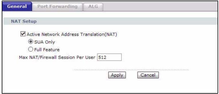
Figure 45 Network > NAT > General
The following table describes the labels in this screen.
Table 24 Network > NAT > General
| LABEL | DESCRIPTION |
| Active Network Address Translation (NAT) | Select this check box to enable NAT. |
| SUA Only | Select this radio button if you have just one public WAN IP address for your P-793H v2. |
| Full Feature | Select this radio button if you have multiple public WAN IP addresses for your P-793H v2. |
| Max NAT/ Firewall Session Per User | When computers use peer to peer applications, such as file sharing applications, they need to establish NAT sessions. If you do not limit the number of NAT sessions a single client can establish, this can result in all of the available NAT sessions being used. In this case, no additional NAT sessions can be established, and users may not be able to access the Internet. Each NAT session establishes a corresponding firewall session. Use this field to limit the number of NAT/ Firewall sessions client computers can establish through the P-793H v2. If your network has a small number of clients using peer to peer applications, you can raise this number to ensure that their performance is not degraded by the number of NAT sessions they can establish. If your network has a large number of users using peer to peer applications, you can lower this number to ensure no single client is exhausting all of the available NAT sessions. |
| Apply | Click this to save your changes. |
| Cancel | Click this to restore your previously saved settings. |
8.3 The Port Forwarding Screen
Note: This screen is available only when you select SUA only in the NAT > General screen.
Use this screen to forward incoming service requests to the server(s) on your local network.
You may enter a single port number or a range of port numbers to be forwarded, and the local IP address of the desired server. The port number identifies a service; for example, web service is on port 80 and FTP on port 21. In some cases, such as for unknown services or where one server can support more than one service (for example both FTP and web service), it might be better to specify a range of port numbers. You can allocate a server IP address that corresponds to a port or a range of ports.
The most often used port numbers and services are shown in Appendix F on page 473. Please refer to RFC 1700 for further information about port numbers.
Note: Many residential broadband ISP accounts do not allow you to run any server processes (such as a Web or FTP server) from your location. Your ISP may periodically check for servers and may suspend your account if it discovers any active services at your location. If you are unsure, refer to your ISP.
Default Server IP Address
In addition to the servers for specified services, NAT supports a default server IP address. A default server receives packets from ports that are not specified in this screen.
Note: If you do not assign a Default Server IP address, the P-793H v2 discards all packets received for ports that are not specified here or in the remote management setup.
Configuring Servers Behind Port Forwarding (Example)
Let's say you want to assign ports 21-25 to one FTP, Telnet and SMTP server (A in the example), port 80 to another (B in the example) and assign a default server IP address of 192.168.1.35 to a third (C in the example). You assign the LAN IP addresses and the ISP assigns the WAN IP address. The NAT network appears as a single host on the Internet.
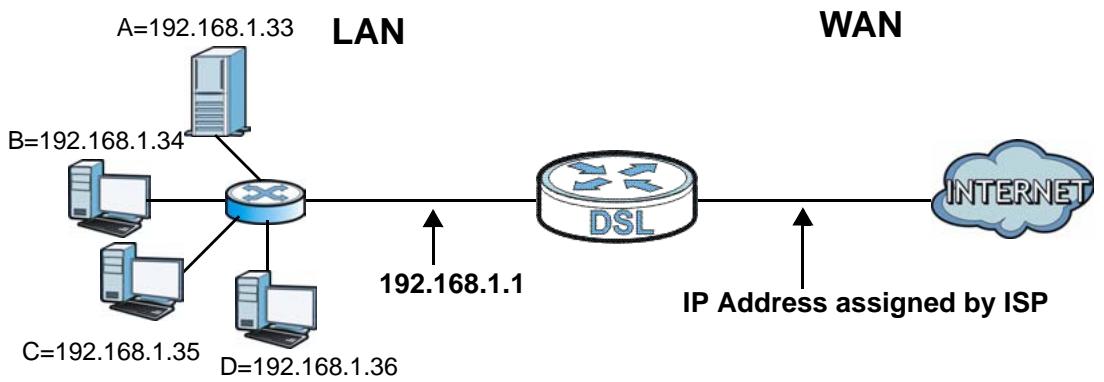
Figure 46 Multiple Servers Behind NAT Example
8.3.1 Configuring the Port Forwarding Screen
Click Network > NAT > Port Forwarding to open the following screen.
See Appendix F on page 473 for port numbers commonly used for particular services.

Figure 47 Network > NAT > Port Forwarding
The following table describes the fields in this screen.
Table 25 Network > NAT > Port Forwarding
| LABEL | DESCRIPTION |
| Default Server Setup | |
| Default Server | In addition to the servers for specified services, NAT supports a default server. A default server receives packets from ports that are not specified in this screen. If you do not assign a Default Server IP address, the P-793H v2 discards all packets received for ports that are not specified here or in the remote management setup. |
| Port Forwarding | |
| Service Name | Select a service from the drop-down list box. |
| Server IP Address | Enter the IP address of the server for the specified service. |
| Add | Click this button to add a rule to the table below. |
| # | This is the rule index number (read-only). |
| Active | This field indicates whether the rule is active or not.Clear the check box to disable the rule. Select the check box to enable it. |
| Service Name | This is a service's name. |
| Start Port | This is the first port number that identifies a service. |
| End Port | This is the last port number that identifies a service. |
| Server IP Address | This is the server's IP address. |
| Modify | Click the edit icon to go to the screen where you can edit the port forwarding rule.Click the delete icon to delete an existing port forwarding rule. Note that subsequent address mapping rules move up by one when you take this action. |
| Apply | Click this to save your changes. |
| Cancel | Click this to restore your previously saved settings. |
8.3.2 The Port Forwarding Rule Edit Screen
Use this screen to edit a port forwarding rule. Click the rule's edit icon in the Port Forwarding screen to display the screen shown next.
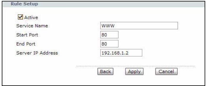
Figure 48 Network > NAT > Port Forwarding: Edit
The following table describes the fields in this screen.
Table 26 Network > NAT > Port Forwarding: Edit
| LABEL | DESCRIPTION |
| Active | Click this check box to enable the rule. |
| Service Name | Enter a name to identify this port-forwarding rule. |
| Start Port | Enter a port number in this field. To forward only one port, enter the port number again in the End Port field. To forward a series of ports, enter the start port number here and the end port number in the End Port field. |
| End Port | Enter a port number in this field. To forward only one port, enter the port number again in the Start Port field above and then enter it again in this field. To forward a series of ports, enter the last port number in a series that begins with the port number in the Start Port field above. |
| Server IP Address | Enter the inside IP address of the server here. |
| Back | Click this to return to the previous screen without saving. |
| Apply | Click this to save your changes. |
| Cancel | Click this to restore your previously saved settings. |
8.4 The Address Mapping Screen
Note: The Address Mapping screen is available only when you select Full Feature in the NAT > General screen.
Ordering your rules is important because the P-793H v2 applies the rules in the order that you specify. When a rule matches the current packet, the P-793H v2 takes the corresponding action and the remaining rules are ignored. If there are any empty rules before your new configured rule, your configured rule will be pushed up by that number of empty rules. For example, if you have already configured rules 1 to 6 in your current set and now you configure rule number 9. In the set summary screen, the new rule will be rule 7, not 9. Now if you delete rule 4, rules 5 to 7 will be pushed up by 1 rule, so old rules 5, 6 and 7 become new rules 4, 5 and 6.
To change your P-793H v2's address mapping settings, click Network > NAT > Address Mapping to open the following screen.
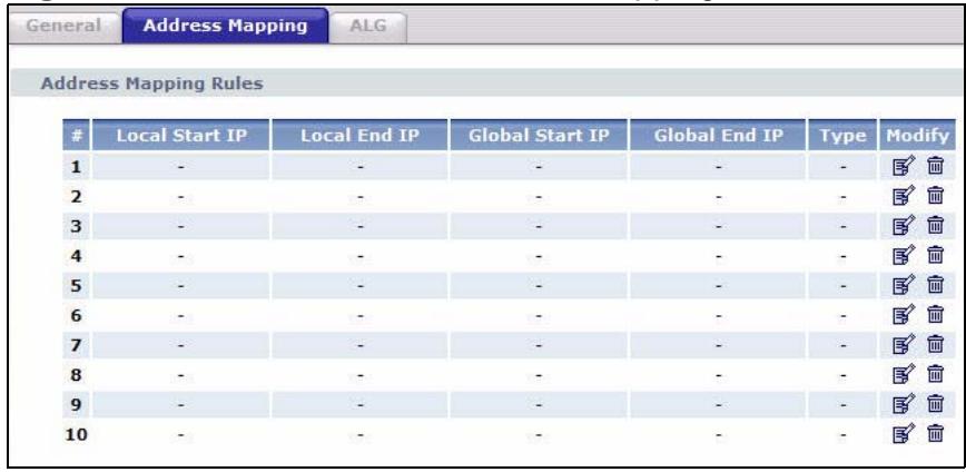
Figure 49 Network > NAT > Address Mapping
The following table describes the fields in this screen.
Table 27 Network > NAT > Address Mapping
| LABEL | DESCRIPTION |
| # | This is the rule index number. |
| Local Start IP | This is the starting Inside Local IP Address (ILA). Local IP addresses are N/A for Server port mapping. |
| Local End IP | This is the end Inside Local IP Address (ILA). If the rule is for all local IP addresses, then this field displays 0.0.0.0 as the Local Start IP address and 255.255.255.255 as the Local End IP address. This field is N/A for One-to-one and Server mapping types. |
| Global Start IP | This is the starting Inside Global IP Address (IGA). Enter 0.0.0.0 here if you have a dynamic IP address from your ISP. You can only do this for Many-to-One and Server mapping types. |
| Global End IP | This is the ending Inside Global IP Address (IGA). This field is N/A for One-to-one, Many-to-One and Server mapping types. |
| Type | 1-1: One-to-one mode maps one local IP address to one global IP address. Note that port numbers do not change for the One-to-one NAT mapping type.M-1: Many-to-One mode maps multiple local IP addresses to one global IP address. This is equivalent to SUA (i.e., PAT, port address translation), ZyXEL's Single User Account feature that previous ZyXEL routers supported only.M-M Ov (Overload): Many-to-Many Overload mode maps multiple local IP addresses to shared global IP addresses.MM No (No Overload): Many-to-Many No Overload mode maps each local IP address to unique global IP addresses Server: This type allows you to specify inside servers of different services behind the NAT to be accessible to the outside world. |
| Modify | Click the edit icon to go to the screen where you can edit the address mapping rule.Click the delete icon to delete an existing address mapping rule. Note that subsequent address mapping rules move up by one when you take this action. |
8.4.1 The Address Mapping Rule Edit Screen
Use this screen to edit an address mapping rule. Click the rule's edit icon in the Address Mapping screen to display the screen shown next.
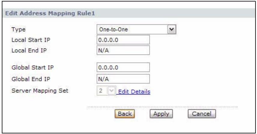
Figure 50 Network > NAT > Address Mapping: Edit
The following table describes the fields in this screen.
Table 28 Network > NAT > Address Mapping: Edit
| LABEL | DESCRIPTION |
| Type | Choose the port mapping type from one of the following. |
| One-to-One: One-to-One mode maps one local IP address to one global IP address. Note that port numbers do not change for One-to-one NAT mapping type. | |
| Many-to-One: Many-to-One mode maps multiple local IP addresses to one global IP address. This is equivalent to SUA (i.e., PAT, port address translation), ZyXEL's Single User Account feature that previous ZyXEL routers supported only. | |
| Many-to-Many Overload: Many-to-Many Overload mode maps multiple local IP addresses to shared global IP addresses. | |
| Many-to-Many No Overload: Many-to-Many No Overload mode maps each local IP address to unique global IP addresses. | |
| Server: This type allows you to specify inside servers of different services behind the NAT to be accessible to the outside world. | |
| Local Start IP | This is the starting local IP address (ILA). Local IP addresses are N/A for Server port mapping. |
| Local End IP | This is the end local IP address (ILA). If your rule is for all local IP addresses, then enter 0.0.0.0 as the Local Start IP address and 255.255.255.255 as the Local End IP address. |
| This field is N/A for One-to-One and Server mapping types. | |
| Global Start IP | This is the starting global IP address (IGA). Enter 0.0.0.0 here if you have a dynamic IP address from your ISP. |
| Global End IP | This is the ending global IP address (IGA). This field is N/A for One-to-One, Many-to-One and Server mapping types. |
| Server Mapping Set | Only available when Type is set to Server. Select a number from the drop-down menu to choose a port forwarding set. |
| Edit Details | Click this link to go to the Port Forwarding screen to edit a port forwarding set that you have selected in the Server Mapping Set field. |
| Back | Click this to return to the previous screen without saving. |
| Apply | Click this to save your changes. |
| Cancel | Click this to restore your previously saved settings. |
8.5 The ALG Screen
Some NAT routers may include a SIP Application Layer Gateway (ALG). A SIP ALG allows SIP calls to pass through NAT by examining and translating IP addresses embedded in the data stream. When the P-793H v2 registers with the SIP register server, the SIP ALG translates the P-793H v2's private IP address inside the SIP data stream to a public IP address. You do not need to use STUN or an outbound proxy if your P-793H v2 is behind a SIP ALG.
Use this screen to enable and disable the SIP (VoIP) ALG in the P-793H v2. To access this screen, click Network > NAT > ALG.
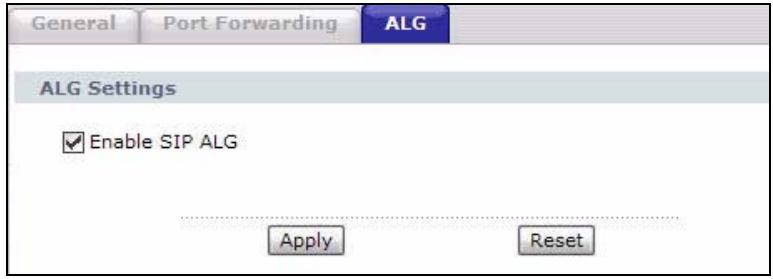
Figure 51 Network > NAT > ALG
The following table describes the fields in this screen.
Table 29 Network > NAT > ALG
| LABEL | DESCRIPTION |
| Enable SIP ALG | Select this to change the private ports or IP in SIP messages so that the VoIP client behind the P-793H v2 can be found in RTP traffic. |
| Apply | Click this to save your changes. |
| Reset | Click this to restore your previously saved settings. |
8.6 NAT Technical Reference
This chapter contains more information regarding NAT.
8.6.1 NAT Definitions
Inside/outside denotes where a host is located relative to the P-793H v2, for example, the computers of your subscribers are the inside hosts, while the web servers on the Internet are the outside hosts.
Global/local denotes the IP address of a host in a packet as the packet traverses a router, for example, the local address refers to the IP address of a host when the
packet is in the local network, while the global address refers to the IP address of the host when the same packet is traveling in the WAN side.
Note that inside/outside refers to the location of a host, while global/local refers to the IP address of a host used in a packet. Thus, an inside local address (ILA) is the IP address of an inside host in a packet when the packet is still in the local network, while an inside global address (IGA) is the IP address of the same inside host when the packet is on the WAN side. The following table summarizes this information.
Table 30 NAT Definitions
| ITEM | DESCRIPTION |
| Inside | This refers to the host on the LAN. |
| Outside | This refers to the host on the WAN. |
| Local | This refers to the packet address (source or destination) as the packet travels on the LAN. |
| Global | This refers to the packet address (source or destination) as the packet travels on the WAN. |
NAT never changes the IP address (either local or global) of an outside host.
8.6.2 What NAT Does
In the simplest form, NAT changes the source IP address in a packet received from a subscriber (the inside local address) to another (the inside global address) before forwarding the packet to the WAN side. When the response comes back, NAT translates the destination address (the inside global address) back to the inside local address before forwarding it to the original inside host. Note that the IP address (either local or global) of an outside host is never changed.
The global IP addresses for the inside hosts can be either static or dynamically assigned by the ISP. In addition, you can designate servers, for example, a web server and a telnet server, on your local network and make them accessible to the outside world. If you do not define any servers (for Many-to-One and Many-to-Many Overload mapping – see Table 31 on page 131), NAT offers the additional benefit of firewall protection. With no servers defined, your P-793H v2 filters out all incoming inquiries, thus preventing intruders from probing your network. For more information on IP address translation, refer to RFC 1631, The IP Network Address Translator (NAT).
8.6.3 How NAT Works
Each packet has two addresses – a source address and a destination address. For outgoing packets, the ILA (Inside Local Address) is the source address on the LAN, and the IGA (Inside Global Address) is the source address on the WAN. For incoming packets, the ILA is the destination address on the LAN, and the IGA is the destination address on the WAN. NAT maps private (local) IP addresses to globally unique ones required for communication with hosts on other networks. It replaces the original IP source address (and TCP or UDP source port numbers for Many-to-One and Many-to-Many Overload NAT mapping) in each packet and then forwards it to the Internet. The P-793H v2 keeps track of the original addresses and port numbers so incoming reply packets can have their original values restored. The following figure illustrates this.
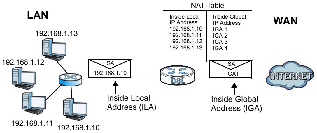
Figure 52 How NAT Works
8.6.4 NAT Application
The following figure illustrates a possible NAT application, where three inside LANs (logical LANs using IP alias) behind the P-793H v2 can communicate with three distinct WAN networks.
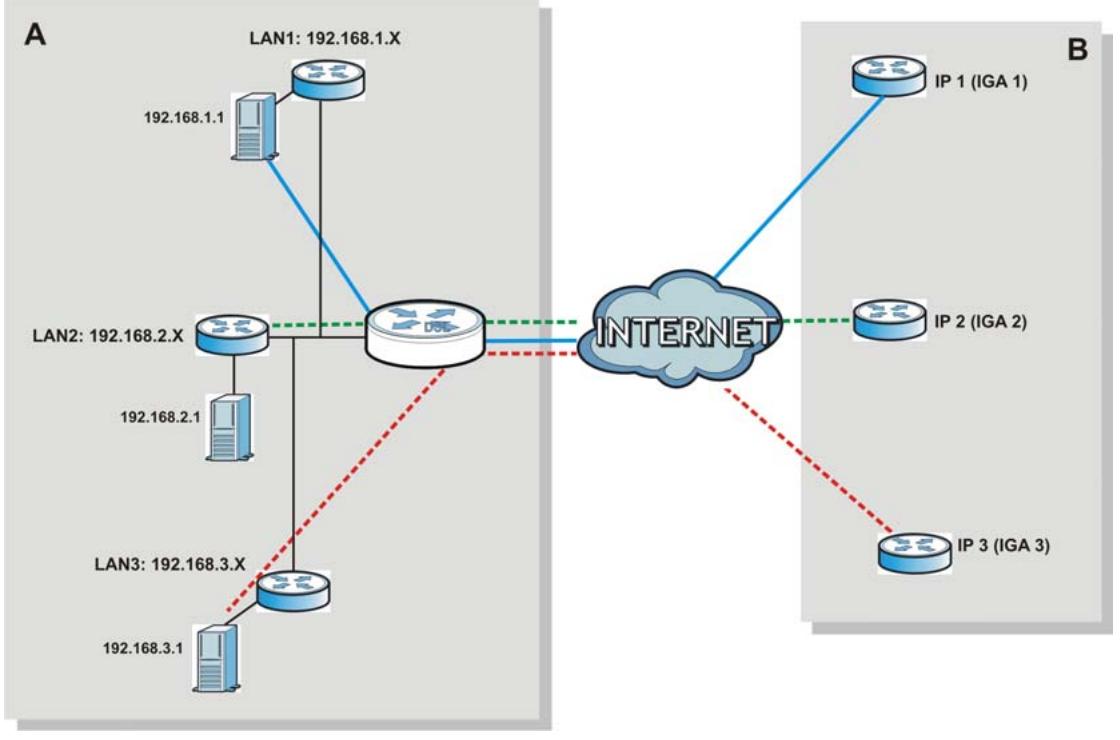
Figure 53 NAT Application With IP Alias
NAT supports five types of IP/port mapping. They are:
- One to One: In One-to-One mode, the P-793H v2 maps one local IP address to one global IP address.
- Many to One: In Many-to-One mode, the P-793H v2 maps multiple local IP addresses to one global IP address. This is equivalent to SUA (for instance, PAT, port address translation), ZyXEL's Single User Account feature that previous ZyXEL routers supported (the SUA Only option in today's routers).
- Many to Many Overload: In Many-to-Many Overload mode, the P-793H v2 maps the multiple local IP addresses to shared global IP addresses.
- Many-to-Many No Overload: In Many-to-Many No Overload mode, the P-793H v2 maps each local IP address to a unique global IP address.
- Server: This type allows you to specify inside servers of different services behind the NAT to be accessible to the outside world.
Port numbers do NOT change for One-to-One and Many-to-Many No Overload NAT mapping types.
The following table summarizes these types.
Table 31 NAT Mapping Types
| TYPE | IP MAPPING |
| One-to-One | ILA1←→ IGA1 |
| Many-to-One (SUA/PAT) | ILA1←→ IGA1 |
| ILA2←→ IGA1 | |
| ... | |
| Many-to-Many Overload | ILA1←→ IGA1 |
| ILA2←→ IGA2 | |
| ILA3←→ IGA1 | |
| ILA4←→ IGA2 | |
| ... | |
| Many-to-Many No Overload | ILA1←→ IGA1 |
| ILA2←→ IGA2 | |
| ILA3←→ IGA3 | |
| ... | |
| Server | Server 1 IP←→ IGA1 |
| Server 2 IP←→ IGA1 | |
| Server 3 IP←→ IGA1 |
Firewalls
9.1 Overview
This chapter shows you how to enable and configure the P-793H v2 firewall. Use these screens to enable and configure the firewall that protects your P-793H v2 and network from attacks by hackers on the Internet and control access to it. By default the firewall:
- allows traffic that originates from your LAN computers to go to all other networks.
- blocks traffic that originates on other networks from going to the LAN.
The following figure illustrates the default firewall action. User A can initiate an IM (Instant Messaging) session from the LAN to the WAN (1). Return traffic for this session is also allowed (2). However other traffic initiated from the WAN is blocked (3 and 4).
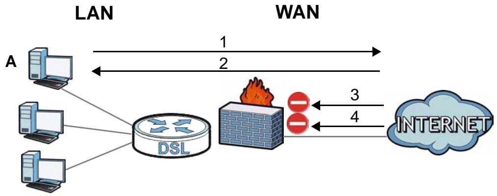
Figure 54 Default Firewall Action
9.1.1 What You Can Do in the Firewall Screens
- Use the General screen (Section 9.2 on page 138) to enable firewall and/or triangle route on the P-793H v2, and set the default action that the firewall takes on packets that do not match any of the firewall rules.
-
Use the Rules screen (Section 9.3 on page 140) to view the configured firewall rules and add,edit or remove a firewall rule.
-
Use the Threshold screen (Section 9.4 on page 145) to set the thresholds that the P-793H v2 uses to determine when to start dropping sessions that do not become fully established (half-open sessions).
9.1.2 What You Need to Know About Firewall
DoS
Denials of Service (DoS) attacks are aimed at devices and networks with a connection to the Internet. Their goal is not to steal information, but to disable a device or network so users no longer have access to network resources. The ZyXEL Device is pre-configured to automatically detect and thwart all known DoS attacks.
Anti-Probing
If an outside user attempts to probe an unsupported port on your P-793H v2, an ICMP response packet is automatically returned. This allows the outside user to know the P-793H v2 exists. The P-793H v2 supports anti-probing, which prevents the ICMP response packet from being sent. This keeps outsiders from discovering your P-793H v2 when unsupported ports are probed.
ICMP
Internet Control Message Protocol (ICMP) is a message control and error-reporting protocol between a host server and a gateway to the Internet. ICMP uses Internet Protocol (IP) datagrams, but the messages are processed by the TCP/IP software and directly apparent to the application user.
DoS Thresholds
For DoS attacks, the P-793H v2 uses thresholds to determine when to drop sessions that do not become fully established. These thresholds apply globally to all sessions. You can use the default threshold values, or you can change them to values more suitable to your security requirements.
Finding Out More
- See Section 9.1.3 on page 135 for an example of setting up a firewall.
- See Section 9.5 on page 149 for advanced technical information on firewall.
9.1.3 Firewall Rule Setup Example
The following Internet firewall rule example allows a hypothetical "MyService" connection from the Internet.
1 Click Security > Firewall > Rules.
2 Select WAN to LAN in the Packet Direction field.
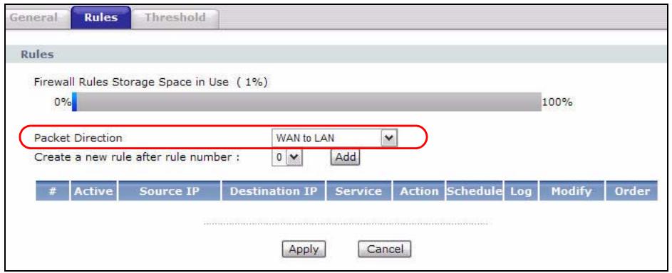
3 In the Rules screen, select the index number after that you want to add the rule. For example, if you select "6", your new rule becomes number 7 and the previous rule 7 (if there is one) becomes rule 8.
4 Click Add to display the firewall rule configuration screen.
5 In the Edit Rule screen, click the Edit Customized Services link to open the Customized Service screen.
6 Click an index number to display the Customized Services Config screen and configure the screen as follows and click Apply.
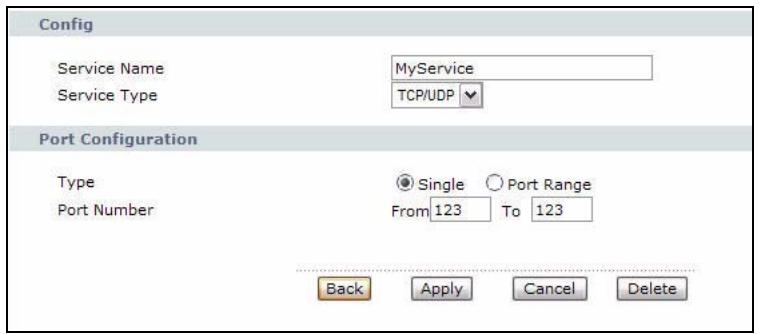
7 Select Any in the Destination Address List box and then click Delete.
8 Configure the destination address screen as follows and click Add.
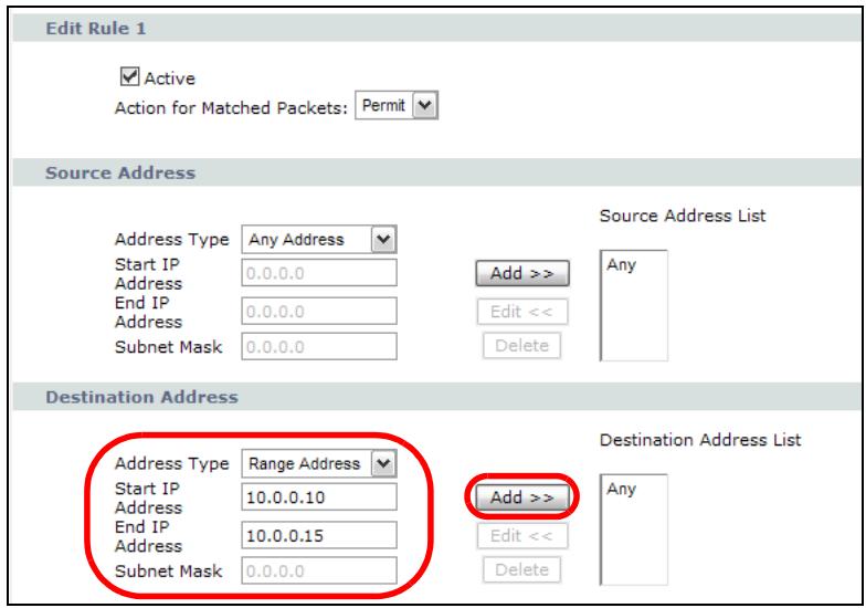
9 Use the Add >> and Remove buttons between Available Services and Selected Services list boxes to configure it as follows. Click Apply when you are done.
Note: Custom services show up with an “*” before their names in the Services list box and the Rules list box.
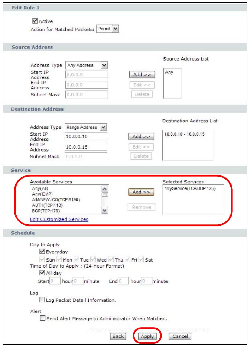
On completing the configuration procedure for this Internet firewall rule, the Rules screen should look like the following.
Rule 1 allows a "MyService" connection from the WAN to IP addresses 10.0.0.10 through 10.0.0.15 on the LAN.
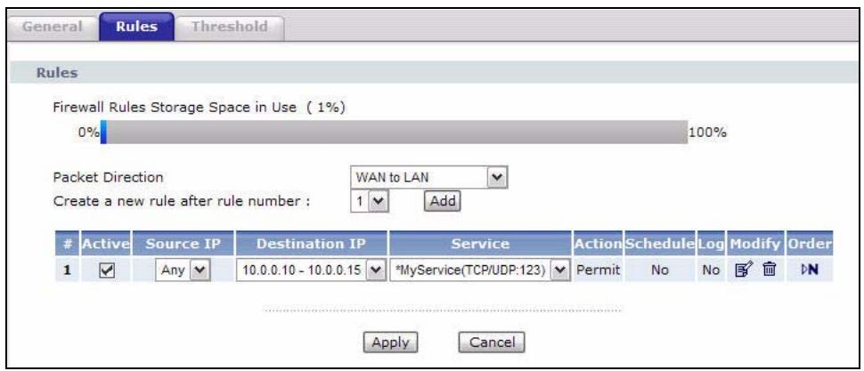
9.2 The Firewall General Screen
Use this screen to configure the firewall settings. Click Security > Firewall to display the following screen.
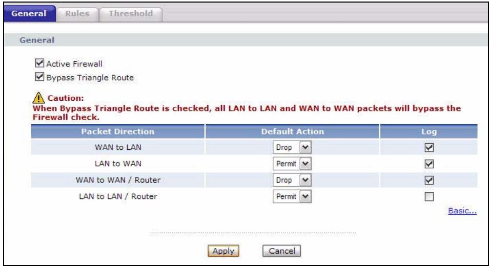
Figure 55 Security > Firewall > General
The following table describes the labels in this screen.
Table 32 Security > Firewall > General
| LABEL | DESCRIPTION |
| Active Firewall | Select this check box to activate the firewall. The P-793H v2 performs access control and protects against Denial of Service (DoS) attacks when the firewall is activated. |
| Bypass Triangle Route | If an alternate gateway on the LAN has an IP address in the same subnet as the P-793H v2's LAN IP address, return traffic may not go through the P-793H v2. This is called an asymmetrical or "triangle" route. This causes the P-793H v2 to reset the connection, as the connection has not been acknowledged. Select this check box to have the P-793H v2 permit the use of asymmetrical route topology on the network (not reset the connection). Note: Allowing asymmetrical routes may let traffic from the WAN go directly to the LAN without passing through the P-793H v2. A better solution is to use IP alias to put the P-793H v2 and the backup gateway on separate subnets. See Section 9.5.4.1 on page 152 for an example. |
| Packet Direction | This is the direction of travel of packets (LAN to LAN / Router, LAN to WAN, WAN to WAN /Router, WAN to LAN). Firewall rules are grouped based on the direction of travel of packets to which they apply. For example, LAN to LAN /Router means packets traveling from a computer/subnet on the LAN to either another computer/subnet on the LAN interface of the P-793H v2 or the P-793H v2 itself. |
| Default Action | Use the drop-down list boxes to select the default action that the firewall is to take on packets that are traveling in the selected direction and do not match any of the firewall rules. Select Drop to silently discard the packets without sending a TCP reset packet or an ICMP destination-unreachable message to the sender. Select Reject to deny the packets and send a TCP reset packet (for a TCP packet) or an ICMP destination-unreachable message (for a UDP packet) to the sender. Select Permit to allow the passage of the packets. |
| Log | Select the check box to create a log (when the above action is taken) for packets that are traveling in the selected direction and do not match any of your customized rules. |
| Expand... | Click this to display more information. |
| Basic... | Click this to display less information. |
| Apply | Click this to save your changes. |
| Cancel | Click this to restore your previously saved settings. |
9.3 The Firewall Rule Screen
Note: The ordering of your rules is very important as rules are applied in turn.
Refer to Section 9.5 on page 149 for more information.
Click Security > Firewall > Rules to bring up the following screen. This screen displays a list of the configured firewall rules. Note the order in which the rules are listed.
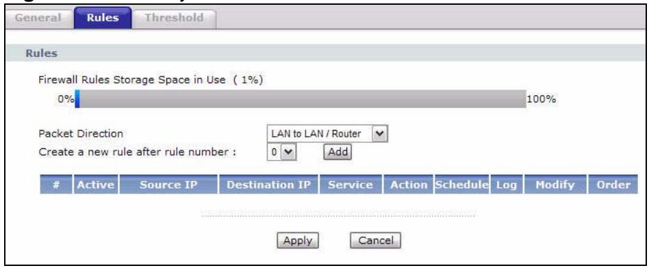
Figure 56 Security > Firewall > Rules
The following table describes the labels in this screen.
Table 33 Security > Firewall > Rules
| LABEL | DESCRIPTION |
| Firewall Rules Storage Space in Use | This read-only bar shows how much of the P-793H v2's memory for recording firewall rules it is currently using. When you are using 80% or less of the storage space, the bar is green. When the amount of space used is over 80%, the bar is red. |
| Packet Direction | Use the drop-down list box to select a direction of travel of packets for which you want to configure firewall rules. |
| Create a new rule after rule number | Select an index number and click Add to add a new firewall rule after the selected index number. For example, if you select "6", your new rule becomes number 7 and the previous rule 7 (if there is one) becomes rule 8. |
| The following read-only fields summarize the rules you have created that apply to traffic traveling in the selected packet direction. The firewall rules that you configure (summarized below) take priority over the general firewall action settings in the General screen. | |
| # | This is your firewall rule number. The ordering of your rules is important as rules are applied in turn. |
| Active | This field displays whether a firewall is turned on or not. Select the check box to enable the rule. Clear the check box to disable the rule. |
| Source IP | This drop-down list box displays the source addresses or ranges of addresses to which this firewall rule applies. Please note that a blank source or destination address is equivalent to Any. |
| Destination IP | This drop-down list box displays the destination addresses or ranges of addresses to which this firewall rule applies. Please note that a blank source ordestination address is equivalent to Any. |
| Service | This drop-down list box displays the services to which this firewall rule applies. See Appendix F on page 473 for more information. |
| Action | This field displays whether the firewall silently discards packets (Drop), discards packets and sends a TCP reset packet or an ICMP destination-unreachable message to the sender (Reject) or allows the passage of packets (Permit). |
| Schedule | This field tells you whether a schedule is specified (Yes) or not (No). |
| Log | This field shows you whether a log is created when packets match this rule (Yes) or not (No). |
| Modify | Click the Edit icon to go to the screen where you can edit the rule. Click the Remove icon to delete an existing firewall rule. A window displays asking you to confirm that you want to delete the firewall rule. Note that subsequent firewall rules move up by one when you take this action. |
| Order | Click the Move icon to display theMove the rule to field. Type a number in theMove the rule to field and click theMove button to move the rule to the number that you typed. The ordering of your rules is important as they are applied in order of their numbering. |
| Apply | Click this to save your changes. |
| Cancel | Click this to restore your previously saved settings. |
9.3.1 Configuring Firewall Rules
Refer to Section 9.1.2 on page 134 for more information.
Use this screen to configure firewall rules. In the Rules screen, select an index number and click Add or click a rule's Edit icon to display this screen and refer to the following table for information on the labels.
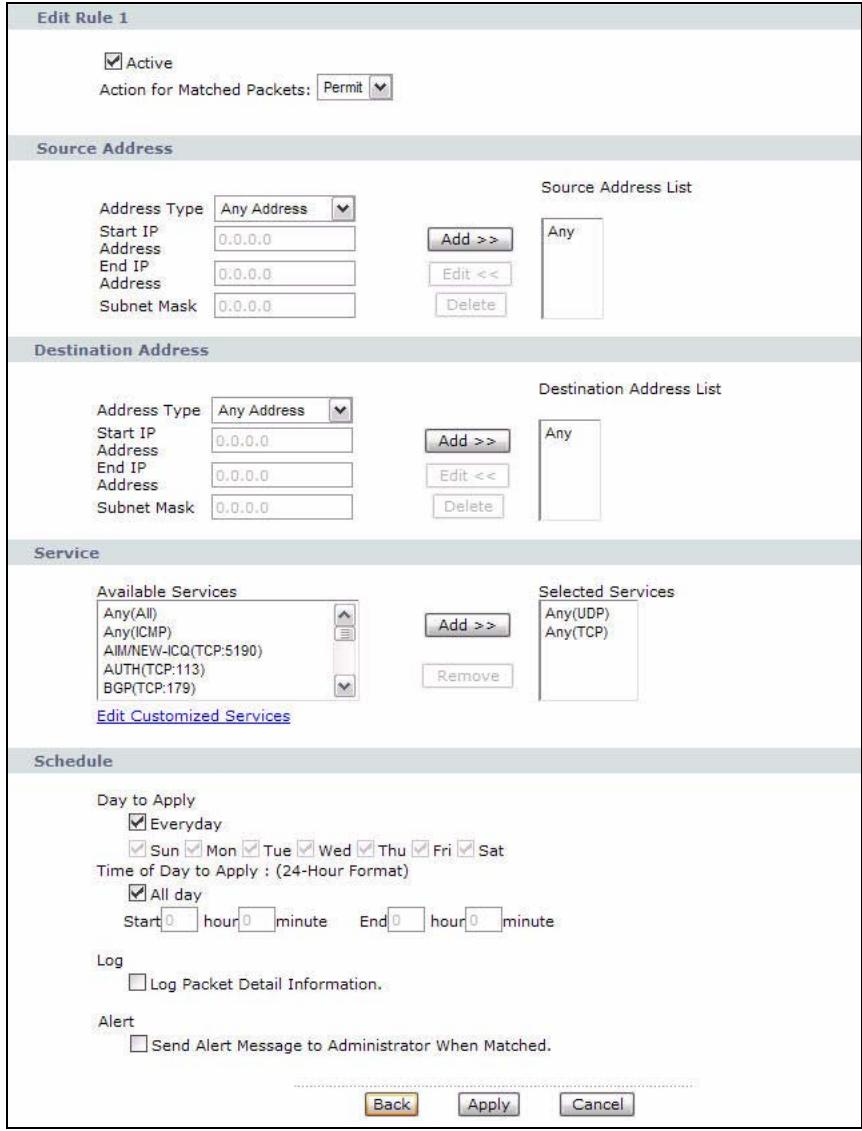
Figure 57 Security > Firewall > Rules: Edit
The following table describes the labels in this screen.
Table 34 Security > Firewall > Rules: Edit
| LABEL | DESCRIPTION |
| Edit Rule | |
| Active | Select this option to enable this firewall rule. |
| Action for Matched Packet | Use the drop-down list box to select whether to discard (Drop), deny and send an ICMP destination-unreachable message to the sender of (Reject) or allow the passage of (Permit) packets that match this rule. |
| Destination Address | |
| Address Type | Do you want your rule to apply to packets with a particular (single) IP, a range of IP addresses (for instance, 192.168.1.10 to 192.169.1.50), a subnet or any IP address? Select an option from the drop-down list box that includes: Single Address, Range Address, Subnet Address and Any Address. |
| Start IP Address | Enter the single IP address or the starting IP address in a range here. |
| End IP Address | Enter the ending IP address in a range here. |
| Subnet Mask | Enter the subnet mask here, if applicable. |
| Add >> | Click Add >> to add a new address to the Source or Destination Address box. You can add multiple addresses, ranges of addresses, and/or subnets. |
| Edit << | To edit an existing source or destination address, select it from the box and click Edit << . |
| Delete | Highlight an existing source or destination address from the Source or Destination Address box above and click Delete to remove it. |
| Services | |
| Available/ Selected Services | Please see Appendix F on page 473 for more information on services available. Highlight a service from the Available Services box on the left, then click Add >> to add it to the Selected Services box on the right. To remove a service, highlight it in the Selected Services box on the right, then click Remove. |
| Edit Customized Service | Click the Edit Customized Services link to bring up the screen that you use to configure a new custom service that is not in the predefined list of services. |
| Schedule | |
| Day to Apply | Select everyday or the day(s) of the week to apply the rule. |
| Time of Day to Apply (24-Hour Format) | Select All Day or enter the start and end times in the hour-minute format to apply the rule. |
| Log | |
| Log Packet Detail Information | This field determines if a log for packets that match the rule is created or not. Go to the Log Settings page and select the Access Control logs category to have the P-793H v2 record these logs. |
| Alert | |
| Send Alert Message to Administrator When Matched | Select the check box to have the P-793H v2 generate an alert when the rule is matched. |
| Back | Click this to return to the previous screen without saving. |
| Apply | Click this to save your changes. |
| Cancel | Click this to restore your previously saved settings. |
9.3.2 Customized Services
Configure customized services and port numbers not predefined by the P-793H v2. For a comprehensive list of port numbers and services, visit the IANA (Internet Assigned Number Authority) website. See Appendix F on page 473 for some examples. Click the Edit Customized Services link while editing a firewall rule to configure a custom service port. This displays the following screen.
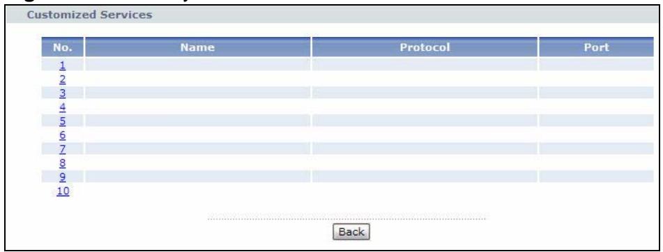
Figure 58 Security > Firewall > Rules: Edit: Edit Customized Services
The following table describes the labels in this screen.
Table 35 Security > Firewall > Rules: Edit: Edit Customized Services
| LABEL | DESCRIPTION |
| No. | This is the number of your customized port. Click a rule's number of a service to go to the Firewall Customized Services Config screen to configure or edit a customized service. |
| Name | This is the name of your customized service. |
| Protocol | This shows the IP protocol (TCP, UDP or TCP/UDP) that defines your customized service. |
| Port | This is the port number or range that defines your customized service. |
| Back | Click this to return to the Firewall Edit Rule screen. |
9.3.3 Configuring a Customized Service
Use this screen to add a customized rule or edit an existing rule. Click a rule number in the Firewall Customized Services screen to display the following screen.
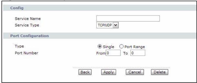
Figure 59 Security > Firewall > Rules: Edit: Edit Customized Services: Config
The following table describes the labels in this screen.
Table 36 Security > Firewall > Rules: Edit: Edit Customized Services: Config
| LABEL | DESCRIPTION |
| Config | |
| Service Name | Type a unique name for your custom port. |
| Service Type | Choose the IP port (TCP, UDP or TCP/UDP) that defines your customized port from the drop down list box. |
| Port Configuration | |
| Type | Click Single to specify one port only or Range to specify a span of ports that define your customized service. |
| Port Number | Type a single port number or the range of port numbers that define your customized service. |
| Back | Click this to return to the previous screen without saving. |
| Apply | Click this to save your changes. |
| Cancel | Click this to restore your previously saved settings. |
| Delete | Click this to delete the current rule. |
9.4 The Firewall Threshold Screen
For DoS attacks, the P-793H v2 uses thresholds to determine when to start dropping sessions that do not become fully established (half-open sessions). These thresholds apply globally to all sessions.
For TCP, half-open means that the session has not reached the established state—the TCP three-way handshake has not yet been completed. Under normal
circumstances, the application that initiates a session sends a SYN (synchronize) packet to the receiving server. The receiver sends back an ACK (acknowledgment) packet and its own SYN, and then the initiator responds with an ACK (acknowledgment). After this handshake, a connection is established.
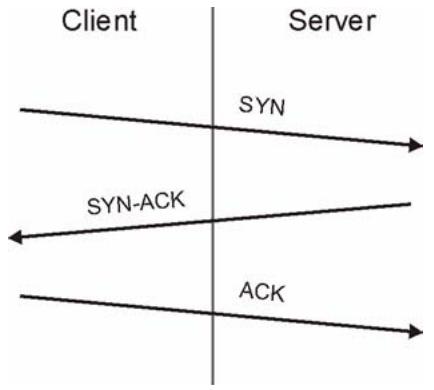
Figure 60 Three-Way Handshake
For UDP, half-open means that the firewall has detected no return traffic. An unusually high number (or arrival rate) of half-open sessions could indicate a DOS attack.
9.4.1 Threshold Values
If everything is working properly, you probably do not need to change the threshold settings as the default threshold values should work for most small offices. Tune these parameters when you believe the P-793H v2 has been receiving DoS attacks that are not recorded in the logs or the logs show that the P-793H v2 is classifying normal traffic as DoS attacks. Factors influencing choices for threshold values are:
1 The maximum number of opened sessions.
2 The minimum capacity of server backlog in your LAN network.
3 The CPU power of servers in your LAN network.
4 Network bandwidth.
5 Type of traffic for certain servers.
Reduce the threshold values if your network is slower than average for any of these factors (especially if you have servers that are slow or handle many tasks and are often busy).
- If you often use P2P applications such as file sharing with eMule or eDonkey, it's recommended that you increase the threshold values since lots of sessions will be established during a small period of time and the P-793H v2 may classify them as DoS attacks.
9.4.2 Configuring Firewall Thresholds
The P-793H v2 also sends alerts whenever TCP Maximum Incomplete is exceeded. The global values specified for the threshold and timeout apply to all TCP connections.
Click Firewall > Threshold to bring up the next screen.
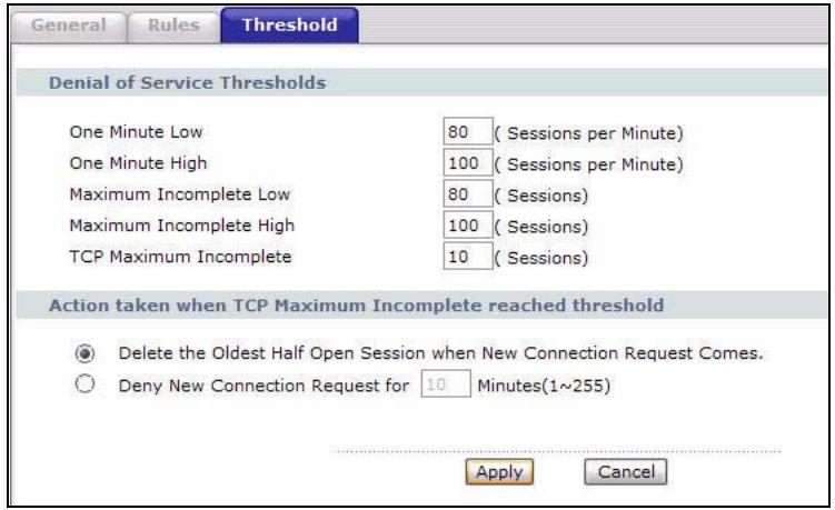
Figure 61 Security > Firewall > Threshold
The following table describes the labels in this screen.
Table 37 Security > Firewall > Threshold
| LABEL | DESCRIPTION |
| Denial of Service Thresholds | The P-793H v2 measures both the total number of existing half-open sessions and the rate of session establishment attempts. Both TCP and UDP half-open sessions are counted in the total number and rate measurements. Measurements are made once a minute. |
| One Minute Low | This is the rate of new half-open sessions per minute that causes the firewall to stop deleting half-open sessions. The P-793H v2 continues to delete half-open sessions as necessary, until the rate of new connection attempts drops below this number. |
| One Minute High | This is the rate of new half-open sessions per minute that causes the firewall to start deleting half-open sessions. When the rate of newconnection attempts rises above this number, the P-793H v2 deleteshalf-open sessions as required to accommodate new connectionattempts.For example, if you set the one minute high to 100, the P-793H v2starts deleting half-open sessions when more than 100 sessionestablishment attempts have been detected in the last minute. It stopsdeleting half-open sessions when the number of session establishmentattempts detected in a minute goes below the number set as the oneminute low. |
| MaximumIncomplete Low | This is the number of existing half-open sessions that causes thefirewall to stop deleting half-open sessions. The P-793H v2 continuesto delete half-open requests as necessary, until the number of existinghalf-open sessions drops below this number. |
| MaximumIncomplete High | This is the number of existing half-open sessions that causes thefirewall to start deleting half-open sessions. When the number ofexisting half-open sessions rises above this number, the P-793H v2deletes half-open sessions as required to accommodate newconnection requests. Do not set Maximum Incomplete High to lowerthan the current Maximum Incomplete Low number.For example, if you set the maximum incomplete high to 100, the P-793H v2 starts deleting half-open sessions when the number ofexisting half-open sessions rises above 100. It stops deleting half-open sessionswhen the number of existing half-open sessions drops belowthe number set as the maximum incomplete low. |
| TCP MaximumIncomplete | An unusually high number of half-open sessions with the samedestination host address could indicate that a DoS attack is beinglaunched against the host.Specify the number of existing half-open TCP sessions with the samedestination host IP address that causes the firewall to start droppinghalf-open sessions to that same destination host IP address. Enter anumber between 1 and 256. As a general rule, you should choose asmaller number for a smaller network, a slower system or limitedbandwidth. The P-793H v2 sends alerts whenever the TCP MaximumIncomplete is exceeded. |
| Action takenwhen TCPMaximumIncompletereachedthreshold | Select the action that P-793H v2 should take when the TCP maximumincomplete threshold is reached. You can have the P-793H v2 either:Delete the oldest half open session when a new connection requestcomes.orDeny new connection requests for the number of minutes that youspecify (between 1 and 255). |
| Apply | Click this to save your changes. |
| Cancel | Click this to restore your previously saved settings. |
9.5 Firewall Technical Reference
This section provides some technical background information about the topics covered in this chapter.
9.5.1 Firewall Rules Overview
Your customized rules take precedence and override the P-793H v2's default settings. The P-793H v2 checks the source IP address, destination IP address and IP protocol type of network traffic against the firewall rules (in the order you list them). When the traffic matches a rule, the P-793H v2 takes the action specified in the rule.
Firewall rules are grouped based on the direction of travel of packets to which they apply:
- LAN to LAN/ Router
- WAN to LAN
LAN to WAN WAN to WAN/Router
By default, the P-793H v2's stateful packet inspection allows packets traveling in the following directions:
- LAN to LAN/ Router
These rules specify which computers on the LAN can manage the P-793H v2 (remote management) and communicate between networks or subnets connected to the LAN interface (IP alias).
Note: You can also configure the remote management settings to allow only a specific computer to manage the P-793H v2.
- LAN to WAN
These rules specify which computers on the LAN can access which computers or services on the WAN.
By default, the P-793H v2's stateful packet inspection drops packets traveling in the following directions:
- WAN to LAN
These rules specify which computers on the WAN can access which computers or services on the LAN.
Note: You also need to configure NAT port forwarding (or full featured NAT address mapping rules) to allow computers on the WAN to access devices on the LAN.
- WAN to WAN/ Router
By default the P-793H v2 stops computers on the WAN from managing the P-793H v2 or using the P-793H v2 as a gateway to communicate with other computers on the WAN. You could configure one of these rules to allow a WAN computer to manage the P-793H v2.
Note: You also need to configure the remote management settings to allow a WAN computer to manage the P-793H v2.
You may define additional rules and sets or modify existing ones but please exercise extreme caution in doing so.
For example, you may create rules to:
- Block certain types of traffic, such as IRC (Internet Relay Chat), from the LAN to the Internet.
- Allow certain types of traffic, such as Lotus Notes database synchronization, from specific hosts on the Internet to specific hosts on the LAN.
- Allow everyone except your competitors to access a web server.
- Restrict use of certain protocols, such as Telnet, to authorized users on the LAN.
These custom rules work by comparing the source IP address, destination IP address and IP protocol type of network traffic to rules set by the administrator. Your customized rules take precedence and override the P-793H v2's default rules.
9.5.2 Guidelines For Enhancing Security With Your Firewall
6 Change the default password via web configurator.
7 Think about access control before you connect to the network in any way.
8 Limit who can access your router.
9 Don't enable any local service (such as telnet or FTP) that you don't use. Any enabled service could present a potential security risk. A determined hacker might be able to find creative ways to misuse the enabled services to access the firewall or the network.
10 For local services that are enabled, protect against misuse. Protect by configuring the services to communicate only with specific peers, and protect by configuring rules to block packets for the services at specific interfaces.
11 Protect against IP spoofing by making sure the firewall is active.
12 Keep the firewall in a secured (locked) room.
9.5.3 Security Considerations
Note: Incorrectly configuring the firewall may block valid access or introduce security risks to the P-793H v2 and your protected network. Use caution when creating or deleting firewall rules and test your rules after you configure them.
Consider these security ramifications before creating a rule:
1 Does this rule stop LAN users from accessing critical resources on the Internet? For example, if IRC is blocked, are there users that require this service?
2 Is it possible to modify the rule to be more specific? For example, if IRC is blocked for all users, will a rule that blocks just certain users be more effective?
3 Does a rule that allows Internet users access to resources on the LAN create a security vulnerability? For example, if FTP ports (TCP 20, 21) are allowed from the Internet to the LAN, Internet users may be able to connect to computers with running FTP servers.
4 Does this rule conflict with any existing rules?
Once these questions have been answered, adding rules is simply a matter of entering the information into the correct fields in the web configurator screens.
9.5.4 Triangle Route
When the firewall is on, your P-793H v2 acts as a secure gateway between your LAN and the Internet. In an ideal network topology, all incoming and outgoing network traffic passes through the P-793H v2 to protect your LAN against attacks.
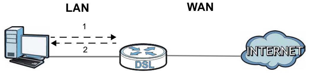
Figure 62 Ideal Firewall Setup
9.5.4.1 The "Triangle Route" Problem
A traffic route is a path for sending or receiving data packets between two Ethernet devices. You may have more than one connection to the Internet (through one or more ISPs). If an alternate gateway is on the LAN (and its IP address is in the same subnet as the P-793H v2's LAN IP address), the "triangle route" (also called asymmetrical route) problem may occur. The steps below describe the "triangle route" problem.
1 A computer on the LAN initiates a connection by sending out a SYN packet to a receiving server on the WAN.
2 The P-793H v2 reroutes the SYN packet through Gateway A on the LAN to the WAN.
3 The reply from the WAN goes directly to the computer on the LAN without going through the P-793H v2.
As a result, the P-793H v2 resets the connection, as the connection has not been acknowledged.
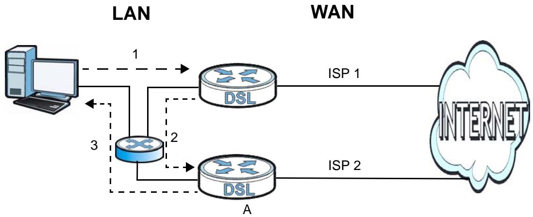
Figure 63 "Triangle Route" Problem
9.5.4.2 Solving the "Triangle Route" Problem
If you have the P-793H v2 allow triangle route sessions, traffic from the WAN can go directly to a LAN computer without passing through the P-793H v2 and its firewall protection.
Another solution is to use IP alias. IP alias allows you to partition your network into logical sections over the same Ethernet interface. Your P-793H v2 supports up to three logical LAN interfaces with the P-793H v2 being the gateway for each logical network.
It's like having multiple LAN networks that actually use the same physical cables and ports. By putting your LAN and Gateway A in different subnets, all returning network traffic must pass through the P-793H v2 to your LAN. The following steps describe such a scenario.
1 A computer on the LAN initiates a connection by sending a SYN packet to a receiving server on the WAN.
2 The P-793H v2 reroutes the packet to Gateway A, which is in Subnet 2.
3 The reply from the WAN goes to the P-793H v2.
4 The P-793H v2 then sends it to the computer on the LAN in Subnet 1.
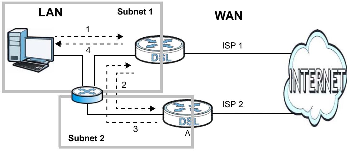
Figure 64 IP Alias
Content Filtering
10.1 Overview
Internet content filtering allows you to block web sites based on keywords in the URL.
See Section 10.1.4 on page 156 for an example of setting up content filtering.
10.1.1 What You Can Do in the Content Filter Screens
- Use the Keyword screen (Section 10.2 on page 158) to block web sites based on a keyword in the URL.
- Use the Schedule screen (Section 10.3 on page 159) to specify the days and times keyword blocking is active.
- Use the Trusted screen (Section 10.4 on page 160) to exclude computers and other devices on your LAN from the keyword blocking filter.
10.1.2 What You Need to Know About Content Filtering
URL
The URL (Uniform Resource Locator) identifies and helps locate resources on a network. On the Internet the URL is the web address that you type in the address bar of your Internet browser, for example "http://www.zyxel.com".
10.1.3 Before You Begin
To use the Trusted screen, you need the IP addresses of devices on your network. See the LAN section (Section 10.4 on page 160) for more information.
10.1.4 Content Filtering Example
The following shows the steps required for a parent (Bob) to set up content filtering on a home network in order to limit his children's access to certain web sites. In the following example, all URLs containing the word 'bad' are blocked.
1 Click Security > Content Filter to display the following screen.
2 Select Active Keyword Blocking.
3 In the Keyword field type keywords to identify websites to be blocked.
4 Click Add Keyword for each keyword to be entered.
5 Click Apply.
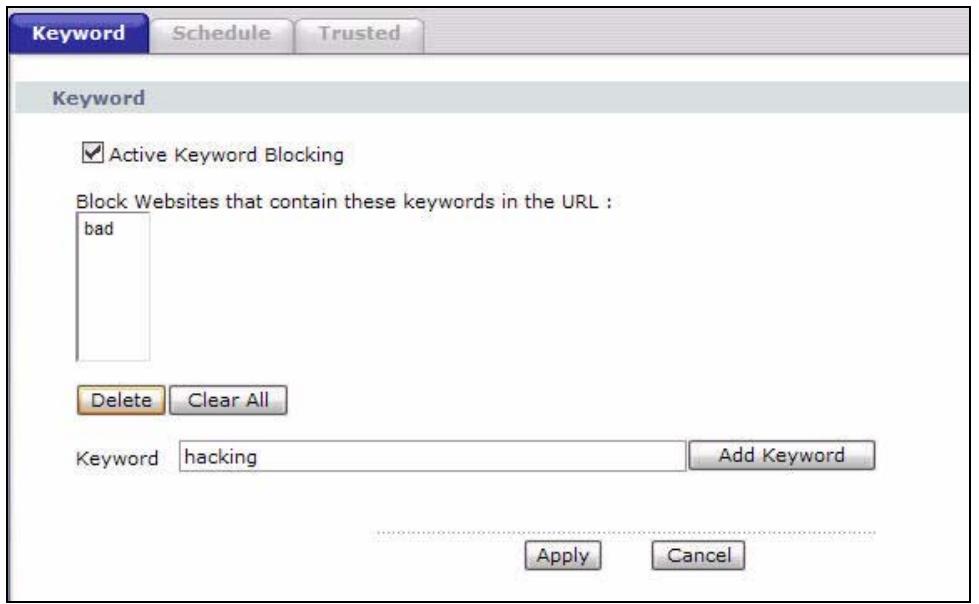
Bob's son arrives home from school at four, while his parents arrive later, at about 7pm. So keyword blocking is enabled for these times on weekdays and not on the weekend when the parents are at home.
1 Click Security > Content Filter > Schedule.
2 Click Edit Daily to Block and select all weekdays.
3 Under Start Time and End Time, type the times for blocking to begin and end (16:00 ~ 17:00 in this example).
4 Click Apply.
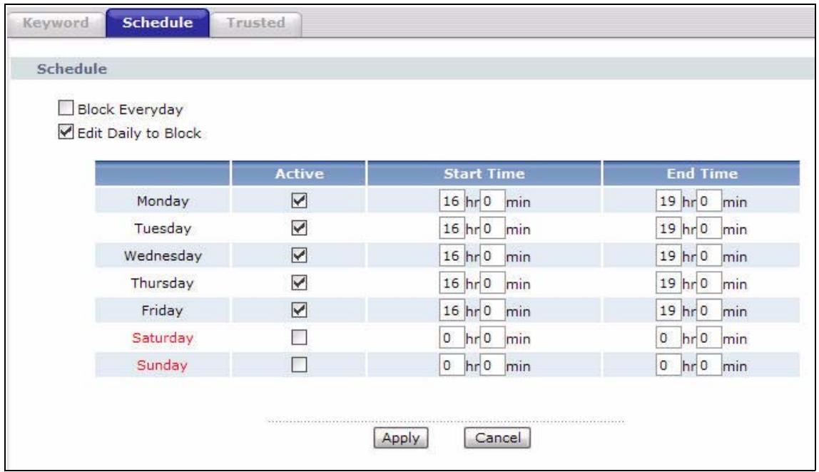
The children can access the family computer in the living room, while only the parents use another computer in the study room. So keyword blocking is only needed on the family computer and the study computer can be excluded from keyword blocking. Bob's home network is on the domain "192.168.1.xxx". Bob gave his home computer a static IP address of 192.168.1.2 and the study computer a static IP address of 192.168.1.3. To exclude the study computer from keyword blocking he follows these steps.
1 Click Security > Content Filter > Trusted.
2 In the Start IP Address and End IP Address fields, type 192.168.1.3.
3 Click Apply.
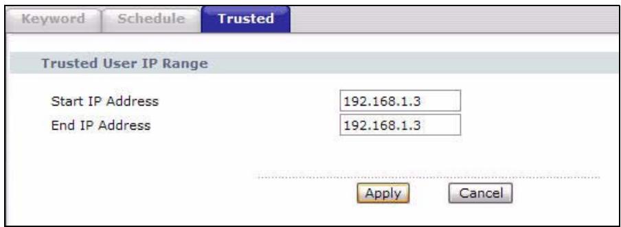
That finishes setting up keyword blocking on the home computer.
10.2 The Keyword Screen
Use this screen to block sites containing certain keywords in the URL. For example, if you enable the keyword "bad", the P-793H v2 blocks all sites containing this keyword including the URL http://www.example.com/bad.html.
To have your P-793H v2 block websites containing keywords in their URLs, click Security > Content Filter. The screen appears as shown.
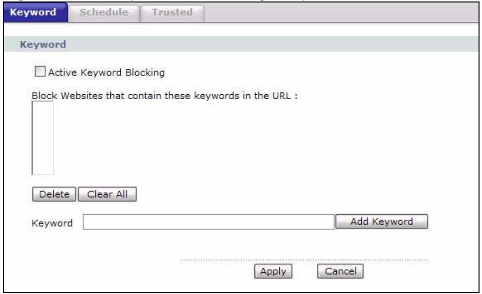
Figure 65 Security > Content Filtering > Keyword
The following table describes the labels in this screen.
Table 38 Security > Content Filtering > Keyword
| LABEL | DESCRIPTION |
| Active Keyword Blocking | Select this check box to enable this feature. |
| Block Websites that contain these keywords in the URL: | This box contains the list of all the keywords that you have configured the P-793H v2 to block. |
| Delete | Highlight a keyword in the box and click this to remove it. |
| Clear All | Click this to remove all of the keywords from the list. |
| Keyword | Type a keyword in this field. You may use any character (up to 127 characters). Wildcards are not allowed. |
| Add Keyword | Click this after you have typed a keyword.Repeat this procedure to add other keywords. Up to 64 keywords are allowed.When you try to access a web page containing a keyword, you will get a message telling you that the content filter is blocking this request. |
| Apply | Click this to save your changes. |
| Cancel | Click this to restore your previously saved settings. |
10.3 The Schedule Screen
Use this screen to set the days and times for the P-793H v2 to perform content filtering. Click Security > Content Filter > Schedule. The screen appears as shown.
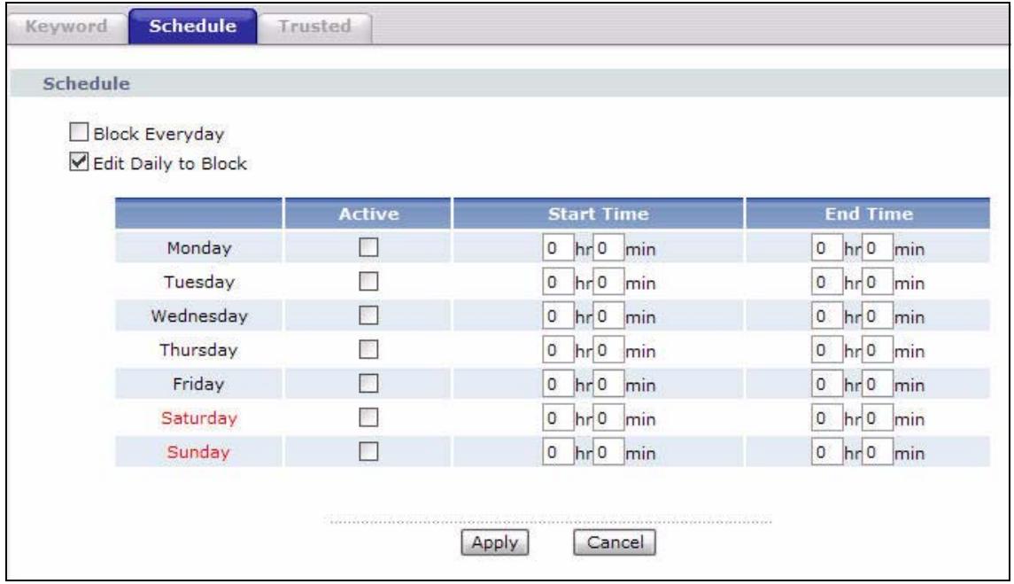
Figure 66 Security > Content Filter > Schedule
The following table describes the labels in this screen.
Table 39 Security > Content Filter: Schedule
| LABEL | DESCRIPTION |
| Schedule | Select Block Everyday to make the content filtering active everyday. Otherwise, select Edit Daily to Block and configure which days of the week (or everyday) and which time of the day you want the content filtering to be active. |
| Active | Select the check box to have the content filtering to be active on the selected day. |
| Start TIme | Enter the time when you want the content filtering to take effect in hour-minute format. |
| End Time | Enter the time when you want the content filtering to stop in hour-minute format. |
| Apply | Click this to save your changes. |
| Cancel | Click this to restore your previously saved settings. |
10.4 The Trusted Screen
Use this screen to exclude a range of users on the LAN from content filtering on your P-793H v2. Click Security > Content Filter > Trusted. The screen appears as shown.
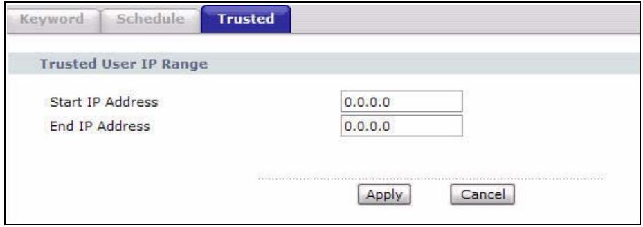
Figure 67 Security > Content Filter: Trusted
The following table describes the labels in this screen.
Table 40 Security > Content Filter: Trusted
| LABEL | DESCRIPTION |
| Start IP Address | Type the IP address of a computer (or the beginning IP address of a specific range of computers) on the LAN that you want to exclude from content filtering. |
| End IP Address | Type the ending IP address of a specific range of users on your LAN that you want to exclude from content filtering. Leave this field blank if you want to exclude an individual computer. |
| Apply | Click this to save your changes. |
| Cancel | Click this to restore your previously saved settings. |
11.1 Overview
A virtual private network (VPN) provides secure communications between sites without the expense of leased site-to-site lines. A secure VPN is a combination of tunneling, encryption, authentication, access control and auditing. It is used to transport traffic over the Internet or any insecure network that uses TCP/IP for communication.
Internet Protocol Security (IPSec) is a standards-based VPN that offers flexible solutions for secure data communications across a public network like the Internet. IPSec is built around a number of standardized cryptographic techniques to provide confidentiality, data integrity and authentication at the IP layer. The following figure is an example of an IPSec VPN tunnel.
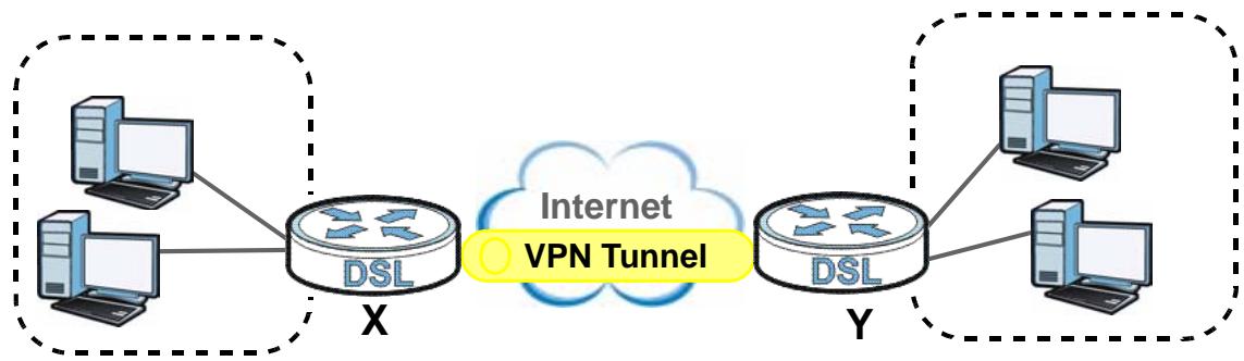
Figure 68 VPN: Example
11.1.1 What You Can Do in the VPN Screens
- Use the Setup screen (Section 11.2 on page 163) to view the configured VPN policies and add, edit or remove a VPN policy.
- Use the Monitor screen (Section 11.7 on page 177) to display and manage the current active VPN connections.
- Use the VPN Global Setting screen (Section 11.8 on page 179) to allow NetBIOS packets passing through the VPN connection.
11.1.2 What You Need to Know About IPSec VPN
A VPN tunnel is usually established in two phases. Each phase establishes a security association (SA), a contract indicating what security parameters the P-793H v2 and the remote IPSec router will use. The first phase establishes an Internet Key Exchange (IKE) SA between the P-793H v2 and remote IPSec router. The second phase uses the IKE SA to securely establish an IPSec SA through which the P-793H v2 and remote IPSec router can send data between computers on the local network and remote network. The following figure illustrates this.
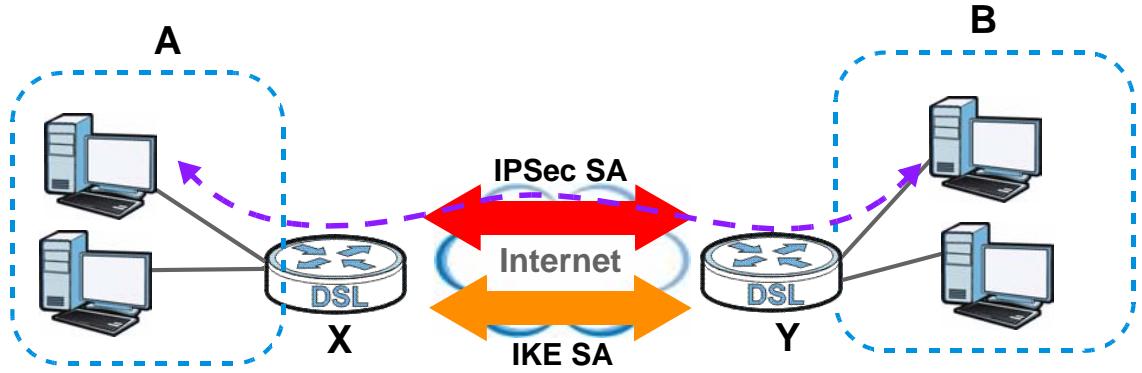
Figure 69 VPN: IKE SA and IPSec SA
In this example, a computer in network A is exchanging data with a computer in network B. Inside networks A and B, the data is transmitted the same way data is normally transmitted in the networks. Between routers X and Y, the data is protected by tunneling, encryption, authentication, and other security features of the IPSec SA. The IPSec SA is established securely using the IKE SA that routers X and Y established first.
My IP Address
My IP Address is the WAN IP address of the P-793H v2. The P-793H v2 has to rebuild the VPN tunnel if My IP Address changes after setup.
The following applies if this field is configured as 0.0.0.0:
- The P-793H v2 uses the current P-793H v2 WAN IP address (static or dynamic) to set up the VPN tunnel.
Secure Gateway Address
Secure Gateway Address is the WAN IP address or domain name of the remote IPSec router (secure gateway).
If the remote secure gateway has a static WAN IP address, enter it in the Secure Gateway Address field. You may alternatively enter the remote secure gateway's domain name (if it has one) in the Secure Gateway Address field.
You can also enter a remote secure gateway's domain name in the Secure Gateway Address field if the remote secure gateway has a dynamic WAN IP address and is using DDNS. The P-793H v2 has to rebuild the VPN tunnel each time the remote secure gateway's WAN IP address changes (there may be a delay until the DDNS servers are updated with the remote gateway's new WAN IP address).
Dynamic Secure Gateway Address
If the remote secure gateway has a dynamic WAN IP address and does not use DDNS, enter 0.0.0.0 as the secure gateway's address. In this case only the remote secure gateway can initiate SAs. This may be useful for telecommuters initiating a VPN tunnel to the company network (see Section 11.9.12 on page 188 for configuration examples).
The Secure Gateway IP Address may be configured as 0.0.0.0 only when using IKE key management and not Manual key management.
Finding Out More
See Section 11.9 on page 179 for advanced technical information on IPSec VPN.
11.1.3 Before You Begin
If a VPN tunnel uses Telnet, FTP, WWW, then you should configure remote management (Remote MGMT) to allow access for that service.
11.2 VPN Setup Screen
The following figure helps explain the main fields in the web configurator.
Figure 70 IPSec Summary Fields
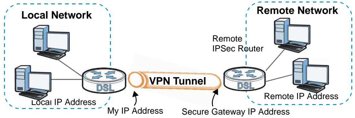
Local and remote IP addresses must be static.
Click Security > VPN to open the VPN Setup screen. This is a menu of your IPSec rules (tunnels). The IPSec summary menu is read-only. Edit a VPN by selecting an index number and then configuring its associated submenus.
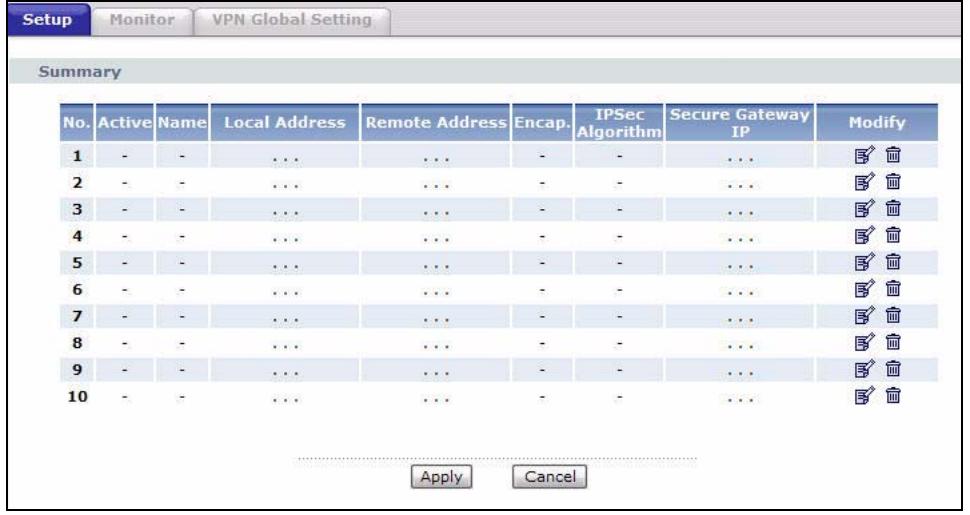
Figure 71 Security >VPN > Setup
The following table describes the fields in this screen.
Table 41 Security >VPN > Setup
| LABEL | DESCRIPTION |
| No. | This is the VPN policy index number. Click a number to edit VPN policies. |
| Active | This field displays whether the VPN policy is active or not. A Yes signifies that this VPN policy is active. No signifies that this VPN policy is not active. |
| Name | This field displays the identification name for this VPN policy. |
| Local Address | This is the IP address(es) of computer(s) on your local network behind your P-793H v2.The same (static) IP address is displayed twice when the Local Address Type field in the VPN Setup - Edit screen is configured to Single.The beginning and ending (static) IP addresses, in a range of computers are displayed when the Local Address Type field in the VPN Setup - Edit screen is configured to Range.A (static) IP address and a subnet mask are displayed when the Local Address Type field in the VPN Setup - Edit screen is configured to Subnet. |
| Remote Address | This is the IP address(es) of computer(s) on the remote network behind the remote IPSec router. |
| This field displays N/A when the Secure Gateway Address field displays 0.0.0.0. In this case only the remote IPSec router can initiate the VPN. | |
| The same (static) IP address is displayed twice when the Remote Address Type field in the VPN Setup - Edit screen is configured to Single. | |
| The beginning and ending (static) IP addresses, in a range of computers are displayed when the Remote Address Type field in the VPN Setup - Edit screen is configured to Range. | |
| A (static) IP address and a subnet mask are displayed when the Remote Address Type field in the VPN Setup - Edit screen is configured to Subnet. | |
| Encap. | This field displays Tunnel or Transport mode (Tunnel is the default selection). |
| IPSec Algorithm | This field displays the security protocols used for an SA. |
| Both AH and ESP increase P-793H v2 processing requirements and communications latency (delay). | |
| Secure Gateway IP | This is the static WAN IP address or URL of the remote IPSec router. This field displays 0.0.0.0 when you configure the Secure Gateway Address field in the VPN-IKE screen to 0.0.0.0. |
| Modify | Click the Edit icon to go to the screen where you can edit the VPN configuration. |
| Click the Remove icon to remove an existing VPN configuration. | |
| Apply | Click this to save your changes and apply them to the P-793H v2. |
| Cancel | Click this return your settings to their last saved values. |
11.3 The VPN Edit Screen
Click an Edit icon in the VPN Setup screen to edit VPN policies.
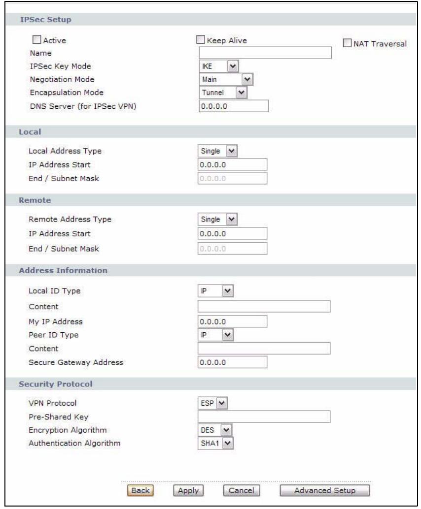
Figure 72 Security >VPN > Setup > Edit
The following table describes the fields in this screen.
Table 42 Security > VPN > Setup > Edit
| LABEL | DESCRIPTION |
| IPSec Setup | |
| Active | Select this check box to activate this VPN policy. This option determines whether a VPN rule is applied before a packet leaves the firewall. |
| Keep Alive | Select either Yes or No from the drop-down list box.Select Yes to have the P-793H v2 automatically reinitiate the SA after the SA lifetime times out, even if there is no traffic. The remote IPSec router must also have keep alive enabled in order for this feature to work. |
Table 42 Security > VPN > Setup > Edit
| LABEL | DESCRIPTION |
| NAT Traversal | This function is available if the VPN Protocol is ESP. Select this check box if you want to set up a VPN tunnel when there are NAT routers between the P-793H v2 and remote IPSec router. The remote IPSec router must also enable NAT traversal, and the NAT routers have to forward UDP port 500 packets to the remote IPSec router behind the NAT router. |
| Name | Type up to 32 characters to identify this VPN policy. You may use any character, including spaces, but the P-793H v2 drops trailing spaces. |
| IPSec Key Mode | Select IKE or Manual from the drop-down list box. IKE provides more protection so it is generally recommended. Manual is a useful option for troubleshooting if you have problems using IKE key management. |
| Negotiation Mode | Select Main or Aggressive from the drop-down list box. Multiple SAs connecting through a secure gateway must have the same negotiation mode. |
| Encapsulation Mode | Select Tunnel mode or Transport mode from the drop-down list box. |
| DNS Server (for IPSec VPN) | If there is a private DNS server that services the VPN, type its IP address here. The P-793H v2 assigns this additional DNS server to the P-793H v2's DHCP clients that have IP addresses in this IPSec rule's range of local addresses.A DNS server allows clients on the VPN to find other computers and servers on the VPN by their (private) domain names. |
| Local | Specify the IP addresses of the devices behind the P-793H v2 that can use the VPN tunnel. The local IP addresses must correspond to the remote IPSec router's configured remote IP addresses.Two active SAs cannot have the local and remote IP address(es) both the same. Two active SAs can have the same local or remote IP address, but not both. You can configure multiple SAs between the same local and remote IP addresses, as long as only one is active at any time. |
| Local Address Type | Use the drop-down menu to choose Single, Range, or Subnet. Select Single for a single IP address. Select Range for a specific range of IP addresses. Select Subnet to specify IP addresses on a network by their subnet mask. |
| IP Address Start | When the Local Address Type field is configured to Single, enter a (static) IP address on the LAN behind your P-793H v2. When the Local Address Type field is configured to Range, enter the beginning (static) IP address, in a range of computers on your LAN behind your P-793H v2. When the Local Address Type field is configured to Subnet, this is a (static) IP address on the LAN behind your P-793H v2. |
| End / Subnet Mask | When the Local Address Type field is configured to Single, this field is N/A. When the Local Address Type field is configured to Range, enter the end (static) IP address, in a range of computers on the LAN behind your P-793H v2. When the Local Address Type field is configured to Subnet, this is a subnet mask on the LAN behind your P-793H v2. |
Table 42 Security > VPN > Setup > Edit
| LABEL | DESCRIPTION |
| Remote | Specify the IP addresses of the devices behind the remote IPSec router that can use the VPN tunnel. The remote IP addresses must correspond to the remote IPSec router's configured local IP addresses. Two active SAs cannot have the local and remote IP address(es) both the same. Two active SAs can have the same local or remote IP address, but not both. You can configure multiple SAs between the same local and remote IP addresses, as long as only one is active at any time. |
| Remote Address Type | Use the drop-down menu to choose Single, Range, or Subnet. Select Single with a single IP address. Select Range for a specific range of IP addresses. Select Subnet to specify IP addresses on a network by their subnet mask. |
| IP Address Start | When the Remote Address Type field is configured to Single, enter a (static) IP address on the network behind the remote IPSec router. When the Remote Address Type field is configured to Range, enter the beginning (static) IP address, in a range of computers on the network behind the remote IPSec router. When the Remote Address Type field is configured to Subnet, enter a (static) IP address on the network behind the remote IPSec router. |
| End / Subnet Mask | When the Remote Address Type field is configured to Single, this field is N/A. When the Remote Address Type field is configured to Range, enter the end (static) IP address, in a range of computers on the network behind the remote IPSec router. When the Remote Address Type field is configured to Subnet, enter a subnet mask on the network behind the remote IPSec router. |
| Address Information | |
| Local ID Type | Select IP to identify this P-793H v2 by its IP address. Select DNS to identify this P-793H v2 by a domain name. Select E-mail to identify this P-793H v2 by an e-mail address. |
| Content | When you select IP in the Local ID Type field, type the IP address of your computer in the local Content field. The P-793H v2 automatically uses the IP address in the My IP Address field (refer to the My IP Address field description) if you configure the local Content field to 0.0.0.0 or leave it blank. It is recommended that you type an IP address other than 0.0.0.0 in the local Content field or use the DNS or E-mail ID type in the following situations. When there is a NAT router between the two IPSec routers. When you want the remote IPSec router to be able to distinguish between VPN connection requests that come in from IPSec routers with dynamic WAN IP addresses. When you select DNS or E-mail in the Local ID Type field, type a domain name or e-mail address by which to identify this P-793H v2 in the local Content field. Use up to 31 ASCII characters including spaces, although trailing spaces are truncated. The domain name or e-mail address is for identification purposes only and can be any string. |
Table 42 Security > VPN > Setup > Edit
| LABEL | DESCRIPTION |
| My IP Address | Enter the WAN IP address of your P-793H v2. The VPN tunnel has to be rebuilt if this IP address changes.The following applies if this field is configured as 0.0.0.0:The P-793H v2 uses the current P-793H v2 WAN IP address (static or dynamic) to set up the VPN tunnel. |
| Peer ID Type | Select IP to identify the remote IPSec router by its IP address.Select DNS to identify the remote IPSec router by a domain name.Select E-mail to identify the remote IPSec router by an e-mail address. |
| Content | The configuration of the peer content depends on the peer ID type.For IP, type the IP address of the computer with which you will make the VPN connection. If you configure this field to 0.0.0.0 or leave it blank, the P-793H v2 will use the address in the Secure Gateway Address field (refer to the Secure Gateway Address field description).For DNS or E-mail, type a domain name or e-mail address by which to identify the remote IPSec router. Use up to 31 ASCII characters including spaces, although trailing spaces are truncated. The domain name or e-mail address is for identification purposes only and can be any string.It is recommended that you type an IP address other than 0.0.0.0 or use the DNS or E-mail ID type in the following situations:When there is a NAT router between the two IPSec routers.When you want the P-793H v2 to distinguish between VPN connection requests that come in from remote IPSec routers with dynamic WAN IP addresses. |
| Secure Gateway Address | Type the WAN IP address or the URL (up to 31 characters) of the IPSec router with which you're making the VPN connection. Set this field to 0.0.0.0 if the remote IPSec router has a dynamic WAN IP address (the IPSec Key Mode field must be set to IKE).In order to have more than one active rule with the Secure Gateway Address field set to 0.0.0.0, the ranges of the local IP addresses cannot overlap between rules.If you configure an active rule with 0.0.0.0 in the Secure Gateway Address field and the LAN's full IP address range as the local IP address, then you cannot configure any other active rules with the Secure Gateway Address field set to 0.0.0.0. |
| Security Protocol | |
| VPN Protocol | Select ESP if you want to use ESP (Encapsulation Security Payload).The ESP protocol (RFC 2406) provides encryption as well as some of the services offered by AH. If you select ESP here, you must select options from the Encryption Algorithm and Authentication Algorithm fields (described below). |
Table 42 Security > VPN > Setup > Edit
| LABEL | DESCRIPTION |
| Pre-Shared Key | Click the button to use a pre-shared key for authentication, and type in your pre-shared key. A pre-shared key identifies a communicating party during a phase 1 IKE negotiation. It is called "pre-shared" because you have to share it with another party before you can communicate with them over a secure connection.Type from 8 to 31 case-sensitive ASCII characters or from 16 to 62 hexadecimal ("0-9", "A-F") characters. You must precede a hexadecimal key with a "0x" (zero x), which is not counted as part of the 16 to 62 character range for the key. For example, in "0x0123456789ABCDEF", "0x" denotes that the key is hexadecimal and "0123456789ABCDEF" is the key itself.Both ends of the VPN tunnel must use the same pre-shared key. You will receive a "PYLD_MALFORMED" (payload malformed) packet if the same pre-shared key is not used on both ends. |
| Encryption Algorithm | Select DES, 3DES, AES or NULL from the drop-down list box.When you use one of these encryption algorithms for data communications, both the sending device and the receiving device must use the same secret key, which can be used to encrypt and decrypt the message or to generate and verify a message authentication code. The DES encryption algorithm uses a 56-bit key. Triple DES (3DES) is a variation on DES that uses a 168-bit key. As a result, 3DES is more secure than DES. It also requires more processing power, resulting in increased latency and decreased throughput. This implementation of AES uses a 128-bit key. AES is faster than 3DES.Select NULL to set up a tunnel without encryption. When you select NULL, you do not enter an encryption key. |
| Authentication Algorithm | Select SHA1 or MD5 from the drop-down list box. MD5 (Message Digest 5) and SHA1 (Secure Hash Algorithm) are hash algorithms used to authenticate packet data. The SHA1 algorithm is generally considered stronger than MD5, but is slower. Select MD5 for minimal security and SHA-1 for maximum security. |
| Back | Click Back to return to the previous screen. |
| Apply | Click Apply to save your changes back to the P-793H v2. |
| Cancel | Click Cancel to begin configuring this screen afresh. |
| Advanced Setup | Click Advanced Setup to configure more detailed settings of your IKE key management. |
11.4 Configuring Advanced IKE Settings
Click Advanced Setup in the VPN Setup-Edit screen to open this screen.
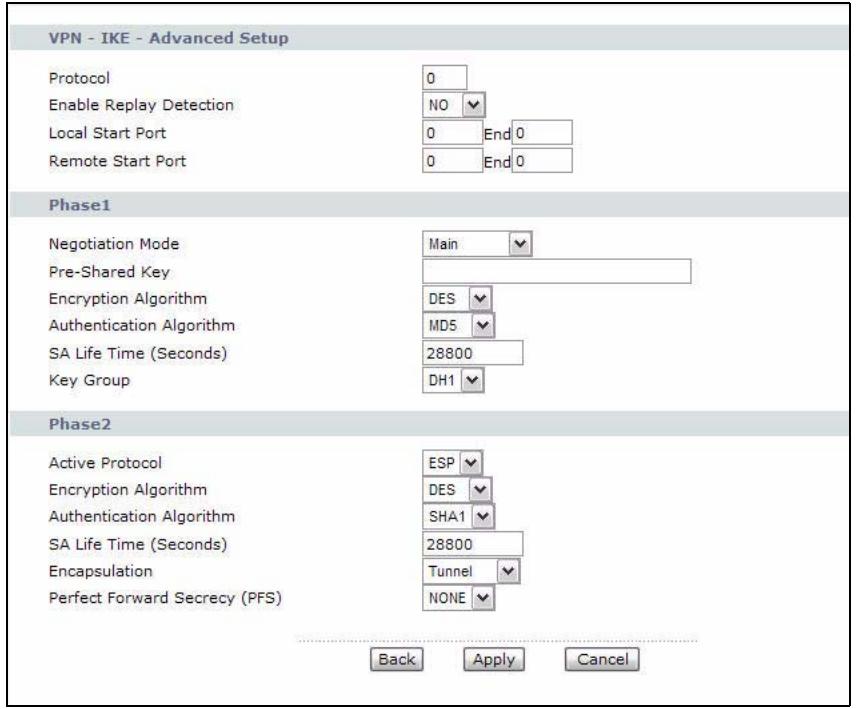
Figure 73 Security >VPN > Setup > Edit > Advanced Setup
The following table describes the fields in this screen.
Table 43 Security > VPN > Setup > Edit > Advanced Setup
| LABEL | DESCRIPTION |
| VPN - IKE - Advanced Setup | |
| Protocol | Enter 1 for ICMP, 6 for TCP, 17 for UDP, and so on. 0 is the default and signifies any protocol. |
| Enable Replay Detection | As a VPN setup is processing intensive, the system is vulnerable to Denial of Service (DoS) attacks The IPSec receiver can detect and reject old or duplicate packets to protect against replay attacks. Select YES from the drop-down menu to enable replay detection, or select NO to disable it. |
| Local Start Port | 0 is the default and signifies any port. Type a port number from 0 to 65535. Some of the most common IP ports are: 21, FTP; 53, DNS; 23, Telnet; 80, HTTP; 25, SMTP; 110, POP3. |
| End | Enter a port number in this field to define a port range. This port number must be greater than that specified in the previous field. If Local Start Port is left at 0, End will also remain at 0. |
| Remote Start Port | 0 is the default and signifies any port. Type a port number from 0 to 65535. Some of the most common IP ports are: 21, FTP; 53, DNS; 23, Telnet; 80, HTTP; 25, SMTP; 110, POP3. |
| End | Enter a port number in this field to define a port range. This port number must be greater then that specified in the previous field. If Remote Start Port is left at 0, End will also remain at 0. |
| Phase 1 | |
| Negotiation Mode | Select Main or Aggressive from the drop-down list box. Multiple SAs connecting through a secure gateway must have the same negotiation mode. |
| Pre-Shared Key | Type your pre-shared key in this field. A pre-shared key identifies a communicating party during a phase 1 IKE negotiation. It is called "pre-shared" because you have to share it with another party before you can communicate with them over a secure connection.Type from 8 to 31 case-sensitive ASCII characters or from 16 to 62 hexadecimal ("0-9", "A-F") characters. You must precede a hexadecimal key with a "0x" (zero x), which is not counted as part of the 16 to 62-character range for the key. For example, in "0x0123456789ABCDEF", "0x" denotes that the key is hexadecimal and "0123456789ABCDEF" is the key itself.Both ends of the VPN tunnel must use the same pre-shared key. You will receive a "PYLD_MALFORMED" (payload malformed) packet if the same pre-shared key is not used on both ends. |
| Encryption Algorithm | Select DES, 3DES or AES from the drop-down list box.When you use one of these encryption algorithms for data communications, both the sending device and the receiving device must use the same secret key, which can be used to encrypt and decrypt the message or to generate and verify a message authentication code. The DES encryption algorithm uses a 56-bit key. Triple DES (3DES) is a variation on DES that uses a 168-bit key. As a result, 3DES is more secure than DES. It also requires more processing power, resulting in increased latency and decreased throughput. This implementation of AES uses a 128-bit key. AES is faster than 3DES. |
| Authentication Algorithm | Select SHA1 or MD5 from the drop-down list box. MD5 (Message Digest 5) and SHA1 (Secure Hash Algorithm) are hash algorithms used to authenticate packet data. The SHA1 algorithm is generally considered stronger than MD5, but is slower. Select MD5 for minimal security and SHA-1 for maximum security. |
| SA Life Time (Seconds) | Define the length of time before an IPSec SA automatically renegotiates in this field. It may range from 60 to 3,000,000 seconds (almost 35 days).A short SA Life Time increases security by forcing the two VPN gateways to update the encryption and authentication keys. However, every time the VPN tunnel renegotiates, all users accessing remote resources are temporarily disconnected. |
| Key Group | You must choose a key group for phase 1 IKE setup. DH1 (default) refers to Diffie-Hellman Group 1 a 768 bit random number. DH2 refers to Diffie-Hellman Group 2 a 1024 bit (1Kb) random number. |
| Phase 2 | |
| Active Protocol | Use the drop-down list box to choose from ESP or AH. |
| Encryption Algorithm | This field is available when you select ESP in the Active Protocol field. Select DES, 3DES, AES or NULL from the drop-down list box. When you use one of these encryption algorithms for data communications, both the sending device and the receiving device must use the same secret key, which can be used to encrypt and decrypt the message or to generate and verify a message authentication code. The DES encryption algorithm uses a 56-bit key. Triple DES (3DES) is a variation on DES that uses a 168-bit key. As a result, 3DES is more secure than DES. It also requires more processing power, resulting in increased latency and decreased throughput. This implementation of AES uses a 128-bit key. AES is faster than 3DES. Select NULL to set up a tunnel without encryption. When you select NULL, you do not enter an encryption key. |
| Authentication Algorithm | Select SHA1 or MD5 from the drop-down list box. MD5 (Message Digest 5) and SHA1 (Secure Hash Algorithm) are hash algorithms used to authenticate packet data. The SHA1 algorithm is generally considered stronger than MD5, but is slower. Select MD5 for minimal security and SHA-1 for maximum security. |
| SA Life Time (Seconds) | Define the length of time before an IKE SA automatically renegotiates in this field. It may range from 60 to 3,000,000 seconds (almost 35 days). A short SA Life Time increases security by forcing the two VPN gateways to update the encryption and authentication keys. However, every time the VPN tunnel renegotiates, all users accessing remote resources are temporarily disconnected. |
| Encapsulation | Select Tunnel mode or Transport mode from the drop-down list box. |
| Perfect Forward Secrecy (PFS) | Perfect Forward Secrecy (PFS) is disabled (NONE) by default in phase 2 IPSec SA setup. This allows faster IPSec setup, but is not so secure. Choose DH1 or DH2 from the drop-down list box to enable PFS. DH1 refers to Diffie-Hellman Group 1 a 768 bit random number. DH2 refers to Diffie-Hellman Group 2 a 1024 bit (1Kb) random number (more secure, yet slower). |
| Back | Click Back to return to the previous screen. |
| Apply | Click Apply to save your changes back to the P-793H v2 and return to the VPN-IKE screen. |
| Cancel | Click Cancel to return to the VPN-IKE screen without saving your changes. |
11.5 Manual Key Setup
Manual key management is useful if you have problems with IKE key management.
11.5.1 Security Parameter Index (SPI)
An SPI is used to distinguish different SAs terminating at the same destination and using the same IPSec protocol. This data allows for the multiplexing of SAs to a single gateway. The SPI (Security Parameter Index) along with a destination IP address uniquely identify a particular Security Association (SA). The SPI is transmitted from the remote VPN gateway to the local VPN gateway. The local VPN gateway then uses the network, encryption and key values that the administrator associated with the SPI to establish the tunnel.
Current ZyXEL implementation assumes identical outgoing and incoming SPIs.
11.6 Configuring Manual Key
You only configure VPN manual key when you select Manual in the IPSec Key Mode field on the VPN Setup-Edit screen. This is the VPN Setup - Manual Key screen as shown next.
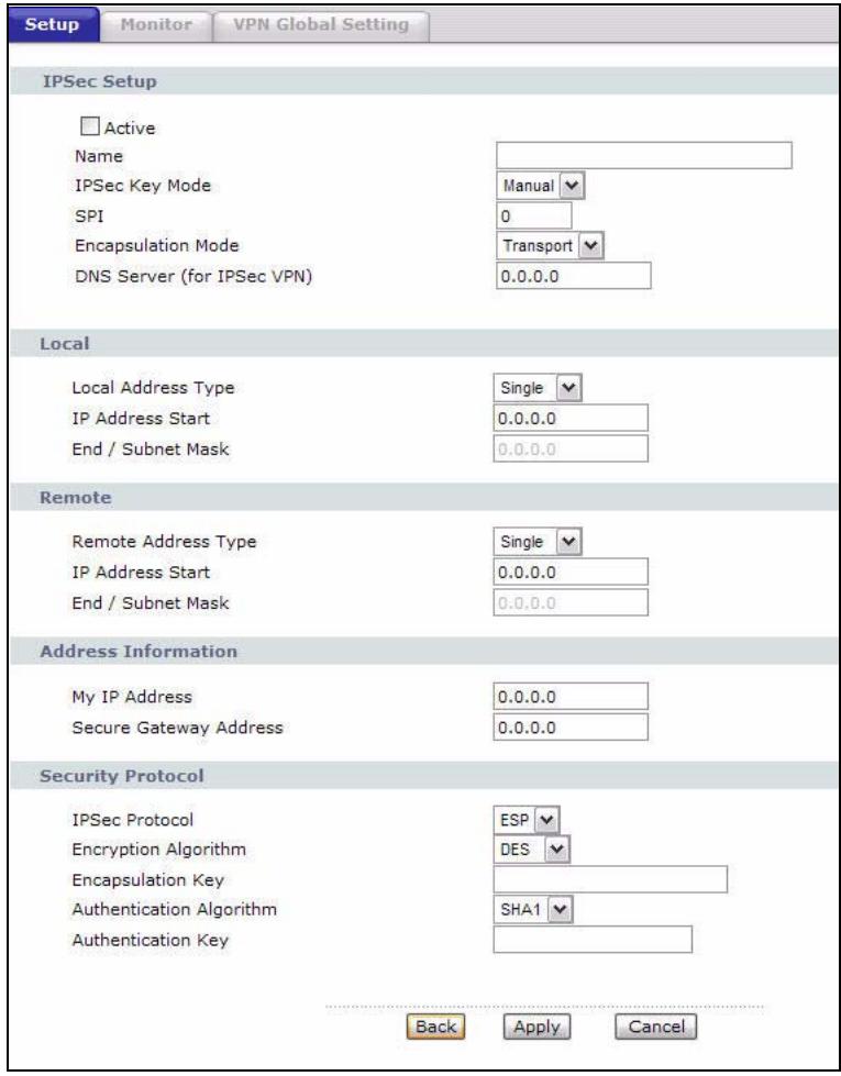
Figure 74 Security > VPN > Setup > Manual Key
The following table describes the fields in this screen.
Table 44 Security > VPN > Setup > Manual Key
| LABEL | DESCRIPTION |
| IPSec Setup | |
| Active | Select this check box to activate this VPN policy. |
| Name | Type up to 32 characters to identify this VPN policy. You may use any character, including spaces, but the P-793H v2 drops trailing spaces. |
| IPSec Key Mode | Select IKE or Manual from the drop-down list box. Manual is a useful option for troubleshooting if you have problems using IKE key management. |
| SPI | Type a number (base 10) from 1 to 999999 for the Security Parameter Index. |
| Encapsulation Mode | Select Tunnel mode or Transport mode from the drop-down list box. |
| DNS Server (for IPSec VPN) | If there is a private DNS server that services the VPN, type its IP address here. The P-793H v2 assigns this additional DNS server to the P-793H v2 's DHCP clients that have IP addresses in this IPSec rule's range of local addresses.A DNS server allows clients on the VPN to find other computers and servers on the VPN by their (private) domain names. |
| Local | Local IP addresses must be static and correspond to the remote IPSec router's configured remote IP addresses.Two active SAs cannot have the local and remote IP address(es) both the same. Two active SAs can have the same local or remote IP address, but not both. You can configure multiple SAs between the same local and remote IP addresses, as long as only one is active at any time. |
| Local Address Type | Use the drop-down menu to choose Single, Range, or Subnet. Select Single for a single IP address. Select Range for a specific range of IP addresses. Select Subnet to specify IP addresses on a network by their subnet mask. |
| IP Address Start | When the Local Address Type field is configured to Single, enter a (static) IP address on the LAN behind your P-793H v2. When the Local Address Type field is configured to Range, enter the beginning (static) IP address, in a range of computers on your LAN behind your P-793H v2. When the Local Address Type field is configured to Subnet, this is a (static) IP address on the LAN behind your P-793H v2. |
| End / Subnet Mask | When the Local Address Type field is configured to Single, this field is N/A. When the Local Address Type field is configured to Range, enter the end (static) IP address, in a range of computers on the LAN behind your P-793H v2. When the Local Address Type field is configured to Subnet, this is a subnet mask on the LAN behind your P-793H v2. |
| Remote | Remote IP addresses must be static and correspond to the remote IPSec router's configured local IP addresses. Two active SAs cannot have the local and remote IP address(es) both the same. Two active SAs can have the same local or remote IP address, but not both. You can configure multiple SAs between the same local and remote IP addresses, as long as only one is active at any time. |
| Remote Address Type | Use the drop-down menu to choose Single, Range, or Subnet. Select Single with a single IP address. Select Range for a specific range of IP addresses. Select Subnet to specify IP addresses on a network by their subnet mask. |
| IP Address Start | When the Remote Address Type field is configured to Single, enter a (static) IP address on the network behind the remote IPSec router. When the Remote Address Type field is configured to Range, enter the beginning (static) IP address, in a range of computers on the network behind the remote IPSec router. When the Remote Address Type field is configured to Subnet, enter a (static) IP address on the network behind the remote IPSec router. |
| End / Subnet Mask | When the Remote Address Type field is configured to Single, this field is N/A. When the Remote Address Type field is configured to Range, enter the end (static) IP address, in a range of computers on the network behind the remote IPSec router. When the Remote Address Type field is configured to Subnet, enter a subnet mask on the network behind the remote IPSec router. |
| Address Information | |
| My IP Address | Enter the WAN IP address of your P-793H v2. The VPN tunnel has to be rebuilt if this IP address changes. The following applies if this field is configured as 0.0.0.0: The P-793H v2 uses the current P-793H v2 WAN IP address (static or dynamic) to set up the VPN tunnel. |
| Secure Gateway Address | Type the WAN IP address or the URL (up to 31 characters) of the IPSec router with which you're making the VPN connection. |
| Security Protocol | |
| IPSec Protocol | Select ESP if you want to use ESP (Encapsulation Security Payload). The ESP protocol (RFC 2406) provides encryption as well as some of the services offered by AH. If you select ESP here, you must select options from the Encryption Algorithm and Authentication Algorithm fields (described next). |
| Encryption Algorithm | Select DES, 3DES or NULL from the drop-down list box. When DES is used for data communications, both sender and receiver must know the same secret key, which can be used to encrypt and decrypt the message or to generate and verify a message authentication code. The DES encryption algorithm uses a 56-bit key. Triple DES (3DES) is a variation on DES that uses a 168-bit key. As a result, 3DES is more secure than DES. It also requires more processing power, resulting in increased latency and decreased throughput. Select NULL to set up a tunnel without encryption. When you select NULL, you do not enter an encryption key. |
| Encapsulation Key (only with ESP) | With DES, type a unique key 8 characters long. With 3DES, type a unique key 24 characters long. Any characters may be used, including spaces, but trailing spaces are truncated. |
| Authentication Algorithm | Select SHA1 or MD5 from the drop-down list box. MD5 (Message Digest 5) and SHA1 (Secure Hash Algorithm) are hash algorithms used to authenticate packet data. The SHA1 algorithm is generally considered stronger than MD5, but is slower. Select MD5 for minimal security and SHA-1 for maximum security. |
| Authentication Key | Type a unique authentication key to be used by IPSec if applicable. Enter 16 characters for MD5 authentication or 20 characters for SHA-1 authentication. Any characters may be used, including spaces, but trailing spaces are truncated. |
| Back | Click Back to return to the previous screen. |
| Apply | Click Apply to save your changes back to the P-793H v2. |
| Cancel | Click Cancel to begin configuring this screen afresh. |
11.7 Viewing SA Monitor
Click Security > VPN > Monitor to open the screen as shown. Use this screen to display and manage active VPN connections.
A Security Association (SA) is the group of security settings related to a specific VPN tunnel. This screen displays active VPN connections. Use Refresh to display active VPN connections. This screen is read-only. The following table describes the fields in this tab.
When there is outbound traffic but no inbound traffic, the SA times out automatically after two minutes. A tunnel with no outbound or inbound traffic is "idle" and does not timeout until the SA lifetime period expires. See Section
11.9.7 on page 185 on keep alive to have the P-793H v2 renegotiate an IPSec SA when the SA lifetime expires, even if there is no traffic.
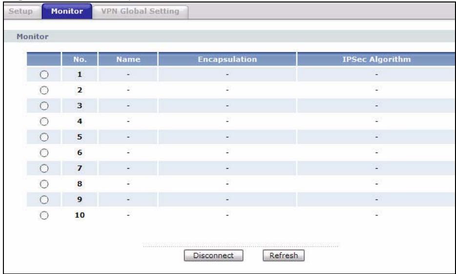
Figure 75 Security >VPN >Monitor
The following table describes the fields in this screen.
Table 45 Security >VPN >Monitor
| LABEL | DESCRIPTION |
| No | This is the security association index number. |
| Name | This field displays the identification name for this VPN policy. |
| Encapsulation | This field displays Tunnel or Transport mode. |
| IPSec Algorithm | This field displays the security protocol, encryption algorithm, and authentication algorithm used in each VPN tunnel. |
| Disconnect | Select one of the security associations, and then click Disconnect to stop that security association. |
| Refresh | Click Refresh to display the current active VPN connection(s). |
11.8 Configuring VPN Global Setting
To change your P-793H v2's global settings, click VPN > VPN Global Setting. The screen appears as shown.
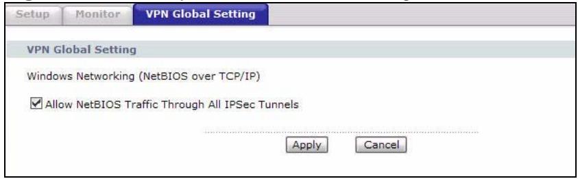
Figure 76 Security > VPN > Global Setting
The following table describes the fields in this screen.
Table 46 Security > VPN > Global Setting
| LABEL | DESCRIPTION |
| Windows Networking (NetBIOS over TCP/IP) | NetBIOS (Network Basic Input/Output System) are TCP or UDP packets that enable a computer to find other computers. It may sometimes be necessary to allow NetBIOS packets to pass through VPN tunnels in order to allow local computers to find computers on the remote network and vice versa. |
| Allow NetBIOS Traffic Through All IPSec Tunnels | Select this check box to send NetBIOS packets through the VPN connection. |
| Apply | Click Apply to save your changes back to the P-793H v2. |
| Cancel | Click Cancel to begin configuring this screen afresh. |
11.9 IPSec VPN Technical Reference
This section provides some technical background information about the topics covered in this chapter.
11.9.1 IPSec Architecture
The overall IPSec architecture is shown as follows.
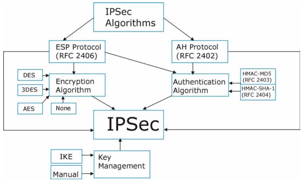
Figure 77 IPSec Architecture
IPSec Algorithms
The ESP (Encapsulating Security Payload) Protocol (RFC 2406) and AH (Authentication Header) protocol (RFC 2402) describe the packet formats and the default standards for packet structure (including implementation algorithms).
The Encryption Algorithm describes the use of encryption techniques such as DES (Data Encryption Standard) and Triple DES algorithms.
The Authentication Algorithms, HMAC-MD5 (RFC 2403) and HMAC-SHA-1 (RFC 2404), provide an authentication mechanism for the AH and ESP protocols.
Key Management
Key management allows you to determine whether to use IKE (ISAKMP) or manual key configuration in order to set up a VPN.
11.9.2 IPSec and NAT
Read this section if you are running IPSec on a host computer behind the P-793H v2.
NAT is incompatible with the AH protocol in both Transport and Tunnel mode. An IPSec VPN using the AH protocol digitally signs the outbound packet, both data
payload and headers, with a hash value appended to the packet. When using AH protocol, packet contents (the data payload) are not encrypted.
A NAT device in between the IPSec endpoints will rewrite either the source or destination address with one of its own choosing. The VPN device at the receiving end will verify the integrity of the incoming packet by computing its own hash value, and complain that the hash value appended to the received packet doesn't match. The VPN device at the receiving end doesn't know about the NAT in the middle, so it assumes that the data has been maliciously altered.
IPSec using ESP in Tunnel mode encapsulates the entire original packet (including headers) in a new IP packet. The new IP packet's source address is the outbound address of the sending VPN gateway, and its destination address is the inbound address of the VPN device at the receiving end. When using ESP protocol with authentication, the packet contents (in this case, the entire original packet) are encrypted. The encrypted contents, but not the new headers, are signed with a hash value appended to the packet.
Tunnel mode ESP with authentication is compatible with NAT because integrity checks are performed over the combination of the "original header plus original payload," which is unchanged by a NAT device.
Transport mode ESP with authentication is not compatible with NAT.
Table 47 VPN and NAT
| SECURITY PROTOCOL | MODE | NAT |
| AH | Transport | N |
| AH | Tunnel | N |
| ESP | Transport | N |
| ESP | Tunnel | Y |
11.9.3 VPN, NAT, and NAT Traversal
NAT is incompatible with the AH protocol in both transport and tunnel mode. An IPSec VPN using the AH protocol digitally signs the outbound packet, both data payload and headers, with a hash value appended to the packet, but a NAT device between the IPSec endpoints rewrites the source or destination address. As a result, the VPN device at the receiving end finds a mismatch between the hash value and the data and assumes that the data has been maliciously altered.
NAT is not normally compatible with ESP in transport mode either, but the P-793H v2's NAT Traversal feature provides a way to handle this. NAT traversal allows
you to set up an IKE SA when there are NAT routers between the two IPSec routers.
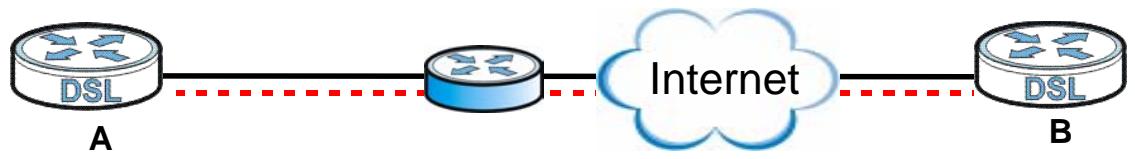
Figure 78 NAT Router Between IPSec Routers
Normally you cannot set up an IKE SA with a NAT router between the two IPSec routers because the NAT router changes the header of the IPSec packet. NAT traversal solves the problem by adding a UDP port 500 header to the IPSec packet. The NAT router forwards the IPSec packet with the UDP port 500 header unchanged. In Figure 78 on page 182, when IPSec router A tries to establish an IKE SA, IPSec router B checks the UDP port 500 header, and IPSec routers A and B build the IKE SA.
For NAT traversal to work, you must:
- Use ESP security protocol (in either transport or tunnel mode).
- Use IKE keying mode.
- Enable NAT traversal on both IPSec endpoints.
- Set the NAT router to forward UDP port 500 to IPSec router A.
Finally, NAT is compatible with ESP in tunnel mode because integrity checks are performed over the combination of the "original header plus original payload," which is unchanged by a NAT device. The compatibility of AH and ESP with NAT in tunnel and transport modes is summarized in the following table.
Table 48 VPN and NAT
| SECURITY PROTOCOL | MODE | NAT |
| AH | Transport | N |
| AH | Tunnel | N |
| ESP | Transport | Y* |
| ESP | Tunnel | Y |
Y* - This is supported in the P-793H v2 if you enable NAT traversal.
11.9.4 Encapsulation
The two modes of operation for IPSec VPNs are Transport mode and Tunnel mode.
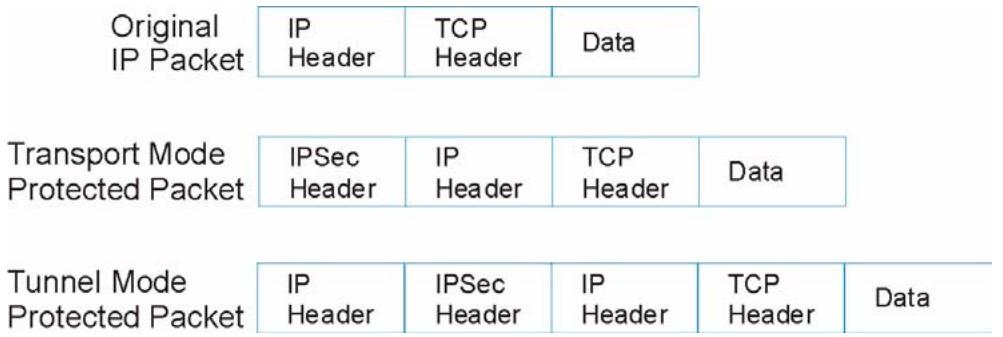
Figure 79 Transport and Tunnel Mode IPSec Encapsulation
Transport Mode
Transport mode is used to protect upper layer protocols and only affects the data in the IP packet. In Transport mode, the IP packet contains the security protocol (AH or ESP) located after the original IP header and options, but before any upper layer protocols contained in the packet (such as TCP and UDP).
With ESP, protection is applied only to the upper layer protocols contained in the packet. The IP header information and options are not used in the authentication process. Therefore, the originating IP address cannot be verified for integrity against the data.
With the use of AH as the security protocol, protection is extended forward into the IP header to verify the integrity of the entire packet by use of portions of the original IP header in the hashing process.
Tunnel Mode
Tunnel mode encapsulates the entire IP packet to transmit it securely. A Tunnel mode is required for gateway services to provide access to internal systems.
Tunnel mode is fundamentally an IP tunnel with authentication and encryption. This is the most common mode of operation. Tunnel mode is required for gateway to gateway and host to gateway communications. Tunnel mode communications have two sets of IP headers:
- Outside header: The outside IP header contains the destination IP address of the VPN gateway.
- Inside header: The inside IP header contains the destination IP address of the final system behind the VPN gateway. The security protocol appears after the outer IP header and before the inside IP header.
11.9.5 IKE Phases
There are two phases to every IKE (Internet Key Exchange) negotiation – phase 1 (Authentication) and phase 2 (Key Exchange). A phase 1 exchange establishes an IKE SA and the second one uses that SA to negotiate SAs for IPSec.
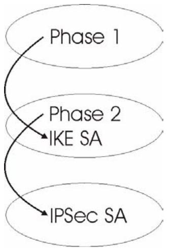
Figure 80 Two Phases to Set Up the IPSec SA
In phase 1 you must:
- Choose a negotiation mode.
- Confirm that the connection is working properly.
- Choose an encryption algorithm.
- Choose an authentication algorithm.
- Choose a Diffie-Hellman public-key cryptography key group (DH1 or DH2).
- Set the IKE SA lifetime. This field allows you to determine how long an IKE SA should stay up before it times out. An IKE SA times out when the IKE SA lifetime period expires. If an IKE SA times out when an IPSec SA is already established, the IPSec SA stays connected.
In phase 2 you must:
- Choose which protocol to use (ESP or AH) for the IKE key exchange.
- Choose an encryption algorithm.
- Choose an authentication algorithm
- Choose whether to enable Perfect Forward Secrecy (PFS) using Diffie-Hellman public-key cryptography. Select None (the default) to disable PFS.
-
Choose Tunnel mode or Transport mode.
-
Set the IPSec SA lifetime. This field allows you to determine how long the IPSec SA should stay up before it times out. The P-793H v2 automatically renegotiates the IPSec SA if there is traffic when the IPSec SA lifetime period expires. The P-793H v2 also automatically renegotiates the IPSec SA if both IPSec routers have keep alive enabled, even if there is no traffic. If an IPSec SA times out, then the IPSec router must renegotiate the SA the next time someone attempts to send traffic.
11.9.6 Negotiation Mode
The phase 1 Negotiation Mode you select determines how the Security Association (SA) will be established for each connection through IKE negotiations.
- Main Mode ensures the highest level of security when the communicating parties are negotiating authentication (phase 1). It uses 6 messages in three round trips: SA negotiation, Diffie-Hellman exchange and an exchange of nonces (a nonce is a random number). This mode features identity protection (your identity is not revealed in the negotiation).
- Aggressive Mode is quicker than Main Mode because it eliminates several steps when the communicating parties are negotiating authentication (phase 1). However the trade-off is that faster speed limits its negotiating power and it also does not provide identity protection. It is useful in remote access situations where the address of the initiator is not known by the responder and both parties want to use pre-shared key authentication.
11.9.7 Keep Alive
When you initiate an IPSec tunnel with keep alive enabled, the P-793H v2 automatically renegotiates the tunnel when the IPSec SA lifetime period expires (see Section 11.9.5 on page 184 for more on the IPSec SA lifetime). In effect, the IPSec tunnel becomes an "always on" connection after you initiate it. Both IPSec routers must have a P-793H v2-compatible keep alive feature enabled in order for this feature to work.
If the P-793H v2 has its maximum number of simultaneous IPSec tunnels connected to it and they all have keep alive enabled, then no other tunnels can take a turn connecting to the P-793H v2 because the P-793H v2 never drops the tunnels that are already connected.
When there is outbound traffic with no inbound traffic, the P-793H v2 automatically drops the tunnel after two minutes.
11.9.8 Remote DNS Server
In cases where you want to use domain names to access Intranet servers on a remote network that has a DNS server, you must identify that DNS server. You
cannot use DNS servers on the LAN or from the ISP since these DNS servers cannot resolve domain names to private IP addresses on the remote network
The following figure depicts an example where three VPN tunnels are created from P-793H v2 A; one to branch office 2, one to branch office 3 and another to headquarters. In order to access computers that use private domain names on the headquarters (HQ) network, the P-793H v2 at branch office 1 uses the Intranet DNS server in headquarters. The DNS server feature for VPN does not work with Windows 2000 or Windows XP.
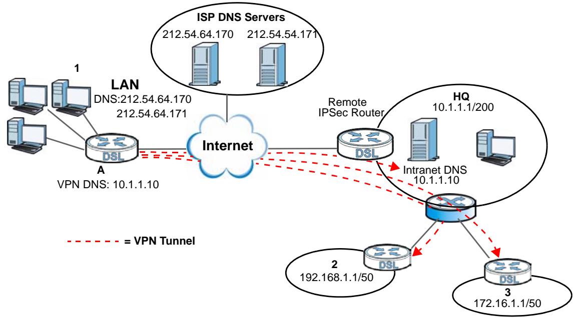
Figure 81 VPN Host using Intranet DNS Server Example
If you do not specify an Intranet DNS server on the remote network, then the VPN host must use IP addresses to access the computers on the remote network.
11.9.9 ID Type and Content
With aggressive negotiation mode (seeSection 11.9.6 on page 185), the P-793H v2 identifies incoming SAs by ID type and content since this identifying information is not encrypted. This enables the P-793H v2 to distinguish between multiple rules for SAs that connect from remote IPSec routers that have dynamic WAN IP addresses. Telecommuters can use separate passwords to simultaneously connect to the P-793H v2 from IPSec routers with dynamic IP addresses (seeSection 11.9.12 on page 188 for a telecommuter configuration example).
Regardless of the ID type and content configuration, the P-793H v2 does not allow you to save multiple active rules with overlapping local and remote IP addresses.
With main mode (seeSection 11.9.6 on page 185), the ID type and content are encrypted to provide identity protection. In this case the P-793H v2 can only
distinguish between up to 12 different incoming SAs that connect from remote IPSec routers that have dynamic WAN IP addresses. The P-793H v2 can distinguish up to 12 incoming SAs because you can select between three encryption algorithms (DES, 3DES and AES), two authentication algorithms (MD5 and SHA1) and two key groups (DH1 and DH2) when you configure a VPN rule (seeSection 11.4 on page 171). The ID type and content act as an extra level of identification for incoming SAs.
The type of ID can be a domain name, an IP address or an e-mail address. The content is the IP address, domain name, or e-mail address.
Table 49 Local ID Type and Content Fields
| LOCAL ID TYPE= | CONTENT= |
| IP | Type the IP address of your computer or leave the field blank to have the P-793H v2 automatically use its own IP address. |
| DNS | Type a domain name (up to 31 characters) by which to identify this P-793H v2. |
| Type an e-mail address (up to 31 characters) by which to identify this P-793H v2. | |
| The domain name or e-mail address that you use in the Content field is used for identification purposes only and does not need to be a real domain name or e-mail address. |
Table 50 Peer ID Type and Content Fields
| PEER ID TYPE= | CONTENT= |
| IP | Type the IP address of the computer with which you will make the VPN connection or leave the field blank to have the P-793H v2 automatically use the address in the Secure Gateway Address field. |
| DNS | Type a domain name (up to 31 characters) by which to identify the remote IPSec router. |
| Type an e-mail address (up to 31 characters) by which to identify the remote IPSec router. | |
| The domain name or e-mail address that you use in the Content field is used for identification purposes only and does not need to be a real domain name or e-mail address. The domain name also does not have to match the remote router's IP address or what you configure in the Secure Gateway Address field below. |
11.9.9.1 ID Type and Content Examples
Two IPSec routers must have matching ID type and content configuration in order to set up a VPN tunnel.
The two P-793H v2s in this example can complete negotiation and establish a VPN tunnel.
Table 51 Matching ID Type and Content Configuration Example
| P-793H V2 A | P-793H V2 B |
| Local ID type: E-mail | Local ID type: IP |
| Local ID content: tom@yourcompany.com | Local ID content: 1.1.1.2 |
| Peer ID type: IP | Peer ID type: E-mail |
| Peer ID content: 1.1.1.2 | Peer ID content: tom@yourcompany.com |
The two P-793H v2s in this example cannot complete their negotiation because P-793H v2 B's Local ID type is IP, but P-793H v2 A's Peer ID type is set to E-mail. An "ID mismatched" message displays in the IPSEC LOG.
Table 52 Mismatching ID Type and Content Configuration Example
| P-793H V2 A | P-793H V2 B |
| Local ID type: IP | Local ID type: IP |
| Local ID content: 1.1.1.10 | Local ID content: 1.1.1.10 |
| Peer ID type: E-mail | Peer ID type: IP |
| Peer ID content: aa@yahoo.com | Peer ID content: N/A |
11.9.10 Pre-Shared Key
A pre-shared key identifies a communicating party during a phase 1 IKE negotiation (see Section 11.9.5 on page 184 for more on IKE phases). It is called "pre-shared" because you have to share it with another party before you can communicate with them over a secure connection.
11.9.11 Diffie-Hellman (DH) Key Groups
Diffie-Hellman (DH) is a public-key cryptography protocol that allows two parties to establish a shared secret over an unsecured communications channel. Diffie-Hellman is used within IKE SA setup to establish session keys. 768-bit (Group 1 - DH1) and 1024-bit (Group 2 - DH2) Diffie-Hellman groups are supported. Upon completion of the Diffie-Hellman exchange, the two peers have a shared secret, but the IKE SA is not authenticated. For authentication, use pre-shared keys.
11.9.12 Telecommuter VPN/IPSec Examples
The following examples show how multiple telecommuters can make VPN connections to a single P-793H v2 at headquarters. The telecommuters use IPSec routers with dynamic WAN IP addresses. The P-793H v2 at headquarters has a static public IP address.
11.9.12.1 Telecommuters Sharing One VPN Rule Example
See the following figure and table for an example configuration that allows multiple telecommuters (A, B and C in the figure) to use one VPN rule to simultaneously access a P-793H v2 at headquarters (HQ in the figure). The telecommuters do not have domain names mapped to the WAN IP addresses of their IPSec routers. The telecommuters must all use the same IPSec parameters but the local IP addresses (or ranges of addresses) should not overlap.
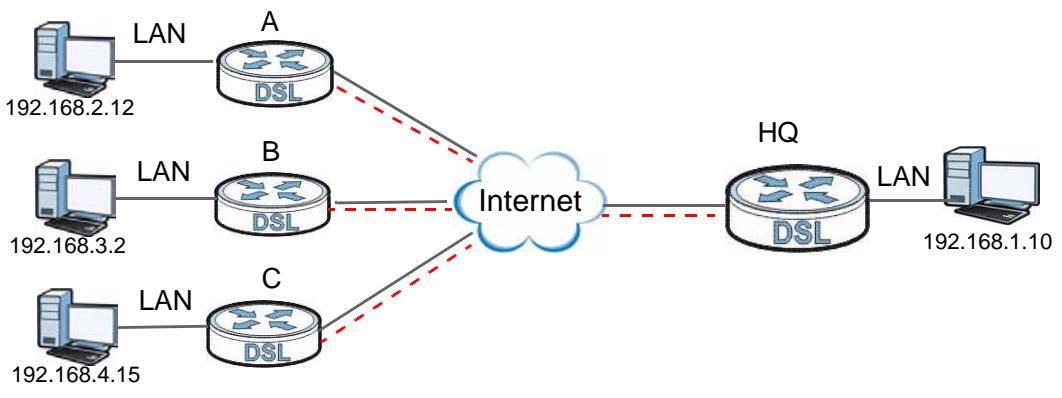
Figure 82 Telecommuters Sharing One VPN Rule Example
Table 53 Telecommuters Sharing One VPN Rule Example
| FIELDS | TELECOMMUTERS | HEADQUARTERS |
| My IP Address: | 0.0.0.0 (dynamic IP address assigned by the ISP) | Public static IP address |
| Secure Gateway IP Address: | Public static IP address | 0.0.0.0 With this IP address only the telecommuter can initiate the IPSec tunnel. |
| Local IP Address: | Telecommuter A: 192.168.2.12 Telecommuter B: 192.168.3.2 Telecommuter C: 192.168.4.15 | 192.168.1.10 |
| Remote IP Address: | 192.168.1.10 | 0.0.0.0 (N/A) |
11.9.12.2 Telecommuters Using Unique VPN Rules Example
In this example the telecommuters (A, B and C in the figure) use IPSec routers with domain names that are mapped to their dynamic WAN IP addresses (use Dynamic DNS to do this).
With aggressive negotiation mode (see Section 11.9.6 on page 185), the P-793H v2 can use the ID types and contents to distinguish between VPN rules.
Telecommuters can each use a separate VPN rule to simultaneously access a P-793H v2 at headquarters. They can use different IPSec parameters. The local IP addresses (or ranges of addresses) of the rules configured on the P-793H v2 at
headquarters can overlap. The local IP addresses of the rules configured on the telecommuters' IPSec routers should not overlap.
See the following table and figure for an example where three telecommuters each use a different VPN rule for a VPN connection with a P-793H v2 located at headquarters. The P-793H v2 at headquarters (HQ in the figure) identifies each incoming SA by its ID type and content and uses the appropriate VPN rule to establish the VPN connection.
The P-793H v2 at headquarters can also initiate VPN connections to the telecommuters since it can find the telecommuters by resolving their domain names.
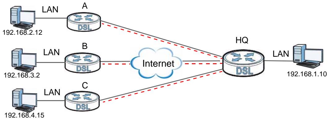
Figure 83 Telecommuters Using Unique VPN Rules Example
Table 54 Telecommuters Using Unique VPN Rules Example
| TELECOMMUTERS | HEADQUARTERS |
| All Telecommuter Rules: | All Headquarters Rules: |
| My IP Address 0.0.0.0 | My IP Address: bigcompanyhq.com |
| Secure Gateway Address: bigcompanyhq.com | Local IP Address: 192.168.1.10 |
| Remote IP Address: 192.168.1.10 | Local ID Type: E-mail |
| Peer ID Type: E-mail | Local ID Content: bob@bigcompanyhq.com |
| Peer ID Content: bob@bigcompanyhq.com | |
| Telecommuter A (telecommutera.dydns.org) | Headquarters P-793H v2 Rule 1: |
| Local ID Type: IP | Peer ID Type: IP |
| Local ID Content: 192.168.2.12 | Peer ID Content: 192.168.2.12 |
| Local IP Address: 192.168.2.12 | Secure Gateway Address: telecommuter1.com |
| Remote Address 192.168.2.12 | |
| Telecommuter B (telecommuterb.dydns.org) | Headquarters P-793H v2 Rule 2: |
| Local ID Type: DNS | Peer ID Type: DNS |
| Local ID Content: telecommuterb.com | Peer ID Content: telecommuterb.com |
| Local IP Address: 192.168.3.2 | Secure Gateway Address: telecommuterb.com |
| Remote Address 192.168.3.2 | |
| Telecommuter C (telecommuterc.dydns.org) | Headquarters P-793H v2 Rule 3: |
| Local ID Type: E-mail | Peer ID Type: E-mail |
| Local ID Content: myVPN@myplace.com | Peer ID Content: myVPN@myplace.com |
| Local IP Address: 192.168.4.15 | Secure Gateway Address: telecommuterc.com |
| Remote Address 192.168.4.15 |
12.1 Overview
This chapter describes how your P-793H v2 can use certificates as a means of authenticating clients. It gives background information about public-key certificates and explains how to use them.
A certificate contains the certificate owner's identity and public key. Certificates provide a way to exchange public keys for use in authentication.
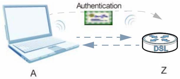
Figure 84 Certificates Example
In the figure above, the P-793H v2 (Z) checks the identity of the notebook (A) using a certificate before granting it access to the network.
12.1.1 What You Need to Know About Certificates
Certification Authority
A Certification Authority (CA) issues certificates and guarantees the identity of each certificate owner. There are commercial certification authorities like CyberTrust or VeriSign and government certification authorities. You can use the P-793H v2 to generate certification requests that contain identifying information and public keys and then send the certification requests to a certification authority.
Certificate File Formats
The certification authority certificate that you want to import has to be in one of these file formats:
- Binary X.509: This is an ITU-T recommendation that defines the formats for X.509 certificates.
- PEM (Base-64) encoded X.509: This Privacy Enhanced Mail format uses lowercase letters, uppercase letters and numerals to convert a binary X.509 certificate into a printable form.
Factory Default Certificate
The P-793H v2 generates its own unique self-signed certificate when you first turn it on. This certificate is referred to in the GUI as the factory default certificate.
12.1.2 Verifying a Certificate
Before you import a trusted certificate into the P-793H v2, you should verify that you have the correct certificate. You can do this using the certificate's fingerprint. A certificate's fingerprint is a message digest calculated using the MD5 or SHA1 algorithm. The following procedure describes how to check a certificate's fingerprint to verify that you have the actual certificate.
1 Browse to where you have the certificate saved on your computer.
2 Make sure that the certificate has a ".cer" or ".crt" file name extension.

Figure 85 Remote Host Certificates
3 Double-click the certificate's icon to open the Certificate window. Click the Details tab and scroll down to the Thumbprint Algorithm and Thumbprint fields.
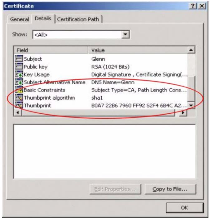
Figure 86 Certificate Details
4 Use a secure method to verify that the certificate owner has the same information in the Thumbprint Algorithm and Thumbprint fields. The secure method may very based on your situation. Possible examples would be over the telephone or through an HTTPS connection.
Finding Out More
See Section 12.3 on page 200 for technical background information on certificates.
12.2 The Trusted CAs Screen
This screen displays a summary list of certificates of the certification authorities that you have set the P-793H v2 to accept as trusted. The P-793H v2 accepts any valid certificate signed by a certification authority on this list as being trustworthy; thus you do not need to import any certificate that is signed by one of these
certification authorities. Click Security > Certificates > Trusted CAs to open the following screen.
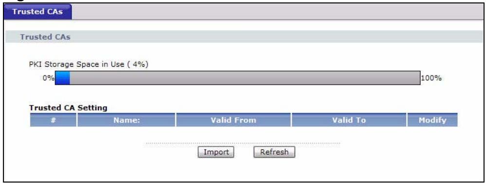
Figure 87 Trusted CAs
The following table describes the labels in this screen.
Table 55 Trusted CAs
| LABEL | DESCRIPTION |
| PKI Storage Space in Use | This bar displays the percentage of the P-793H v2's PKI storage space that is currently in use. The bar turns from blue to red when the maximum is being approached. When the bar is red, you should consider deleting expired or unnecessary certificates before adding more certificates. |
| # | This field displays the certificate index number. The certificates are listed in alphabetical order. |
| Name | This field displays the name used to identify this certificate. |
| Valid From | This field displays the date that the certificate becomes applicable. The text displays in red and includes a Not Yet Valid! message if the certificate has not yet become applicable. |
| Valid To | This field displays the date that the certificate expires. The text displays in red and includes an Expiring! or Expired! message if the certificate is about to expire or has already expired. |
| Modify | Click the Edit icon to open a screen with an in-depth list of information about the certificate. Click the Remove icon to remove the certificate. A window displays asking you to confirm that you want to delete the certificates. Note that subsequent certificates move up by one when you take this action. |
| Import | Click this to open a screen where you can save the certificate of a certification authority that you trust, from your computer to the P-793H v2. |
| Refresh | Click this to display the current validity status of the certificates. |
12.2.1 Trusted CA Import
Follow the instructions in this screen to save a trusted certification authority's certificate to the P-793H v2. Click Security > Certificates to open the Trusted CAs screen and then click Import to open the Trusted CA Import screen.
Note: You must remove any spaces from the certificate's filename before you can import the certificate.
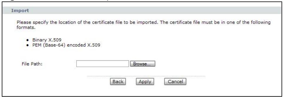
Figure 88 Trusted CA Import
The following table describes the labels in this screen.
Table 56 Trusted CA Import
| LABEL | DESCRIPTION |
| File Path | Type in the location of the file you want to upload in this field or click Browse to find it. |
| Browse | Click this to find the certificate file you want to upload. |
| Back | Click this to return to the previous screen without saving. |
| Apply | Click this to save the certificate on the P-793H v2. |
| Cancel | Click this to restore your previously saved settings. |
12.2.2 Trusted CA Details
Use this screen to view in-depth information about the certification authority's certificate, change the certificate's name and set whether or not you want the P-793H v2 to check a certification authority's list of revoked certificates before trusting a certificate issued by the certification authority. Click Security > Certificates > Trusted CAs to open the Trusted CAs screen. Click the details icon to open the Trusted CA Details screen.

Figure 89 Trusted CA Details
The following table describes the labels in this screen.
Table 57 Trusted CA Details
| LABEL | DESCRIPTION |
| Certificate Name | This field displays the identifying name of this certificate. If you want to change the name, type up to 31 characters to identify this key certificate. You may use any character (not including spaces). |
| Certificate Information | These read-only fields display detailed information about the certificate. |
| Type | This field displays general information about the certificate. CA-signed means that a Certification Authority signed the certificate. Self-signed means that the certificate's owner signed the certificate (not a certification authority). X.509 means that this certificate was created and signed according to the ITU-T X.509 recommendation that defines the formats for public-key certificates. |
| Version | This field displays the X.509 version number. |
| Serial Number | This field displays the certificate's identification number given by the certification authority. |
| Signature Algorithm | This field displays the type of algorithm that was used to sign the certificate. Some certification authorities use rsa-pkcs1-sha1 (RSA public-private key encryption algorithm and the SHA1 hash algorithm). Other certification authorities may use rsa-pkcs1-md5 (RSA public-private key encryption algorithm and the MD5 hash algorithm). |
| Valid From | This field displays the date that the certificate becomes applicable. The text displays in red and includes a Not Yet Valid! message if the certificate has not yet become applicable. |
| Valid To | This field displays the date that the certificate expires. The text displays in red and includes an Expiring! or Expired! message if the certificate is about to expire or has already expired. |
| Key Algorithm | This field displays the type of algorithm that was used to generate the certificate's key pair (the P-793H v2 uses RSA encryption) and the length of the key set in bits (1024 bits for example). |
| MD5 Fingerprint | This is the certificate's message digest that the P-793H v2 calculated using the MD5 algorithm. You can use this value to verify with the certification authority (over the phone for example) that this is actually their certificate. |
| SHA1 Fingerprint | This is the certificate's message digest that the P-793H v2 calculated using the SHA1 algorithm. You can use this value to verify with the certification authority (over the phone for example) that this is actually their certificate. |
| Certificate in PEM (Base-64) Encoded Format | This read-only text box displays the certificate or certification request in Privacy Enhanced Mail (PEM) format. PEM uses 64 ASCII characters to convert the binary certificate into a printable form. You can copy and paste the certificate into an e-mail to send to friends or colleagues or you can copy and paste the certificate into a text editor and save the file on a management computer for later distribution (via floppy disk for example). |
| Back | Click this to return to the previous screen without saving. |
| Export | Click this and then Save in the File Download screen. The Save As screen opens, browse to the location that you want to use and click Save. |
| Apply | Click this to save your changes. You can only change the name and/or set whether or not you want the P-793H v2 to check the CRL that the certification authority issues before trusting a certificate issued by the certification authority. |
| Cancel | Click this to restore your previously saved settings. |
12.3 Certificates Technical Reference
This section provides technical background information about the topics covered in this chapter.
12.3.1 Certificates Overview
The P-793H v2 can use certificates (also called digital IDs) to authenticate users. Certificates are based on public-private key pairs. A certificate contains the certificate owner's identity and public key. Certificates provide a way to exchange public keys for use in authentication.
The P-793H v2 uses certificates based on public-key cryptography to authenticate users attempting to establish a connection, not to encrypt the data that you send after establishing a connection. The method used to secure the data that you send through an established connection depends on the type of connection. For example, a VPN tunnel might use the triple DES encryption algorithm.
The certification authority uses its private key to sign certificates. Anyone can then use the certification authority's public key to verify the certificates.
Advantages of Certificates
Certificates offer the following benefits.
- The P-793H v2 only has to store the certificates of the certification authorities that you decide to trust, no matter how many devices you need to authenticate.
Key distribution is simple and very secure since you can freely distribute public keys and you never need to transmit private keys.
12.3.2 Private-Public Certificates
When using public-key cryptography for authentication, each host has two keys. One key is public and can be made openly available. The other key is private and must be kept secure.
These keys work like a handwritten signature (in fact, certificates are often referred to as "digital signatures"). Only you can write your signature exactly as it should look. When people know what your signature looks like, they can verify whether something was signed by you, or by someone else. In the same way, your private key "writes" your digital signature and your public key allows people to verify whether data was signed by you, or by someone else. This process works as follows.
1 Tim wants to send a message to Jenny. He needs her to be sure that it comes from him, and that the message content has not been altered by anyone else along the way. Tim generates a public key pair (one public key and one private key).
2 Tim keeps the private key and makes the public key openly available. This means that anyone who receives a message seeming to come from Tim can read it and verify whether it is really from him or not.
3 Tim uses his private key to sign the message and sends it to Jenny.
4 Jenny receives the message and uses Tim's public key to verify it. Jenny knows that the message is from Tim, and that although other people may have been able to read the message, no-one can have altered it (because they cannot re-sign the message with Tim's private key).
5 Additionally, Jenny uses her own private key to sign a message and Tim uses Jenny's public key to verify the message.
Static Route
13.1 Overview
The P-793H v2 usually uses the default gateway to route outbound traffic from computers on the LAN to the Internet. To have the P-793H v2 send data to devices not reachable through the default gateway, use static routes.
For example, the next figure shows a computer (A) connected to the P-793H v2's LAN interface. The P-793H v2 routes most traffic from A to the Internet through the P-793H v2's default gateway (R1). You create one static route to connect to services offered by your ISP behind router R2. You create another static route to communicate with a separate network behind a router R3 connected to the LAN.
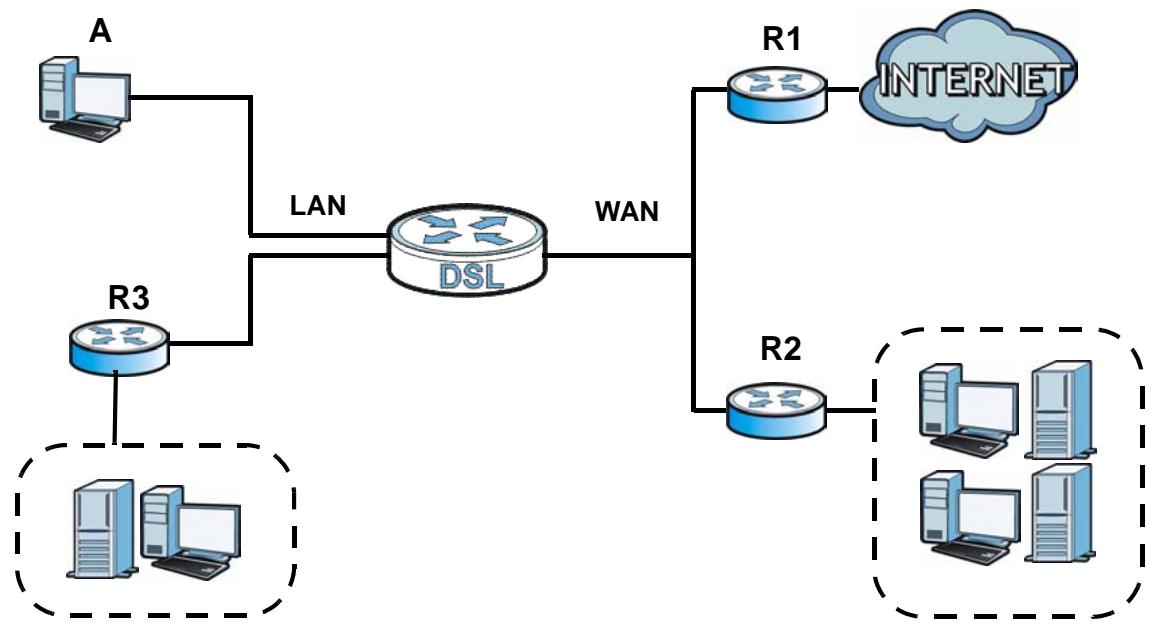
Figure 90 Example of Static Routing Topology
13.2 The Static Route Screen
Use this screen to view the static route rules. Click Advanced > Static Route to open the Static Route screen.
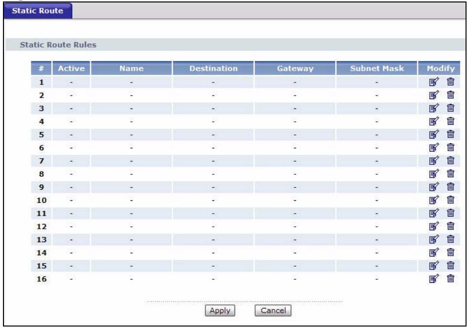
Figure 91 Advanced > Static Route
The following table describes the labels in this screen.
Table 58 Advanced > Static Route
| LABEL | DESCRIPTION |
| # | This is the number of an individual static route. |
| Active | This field indicates whether the rule is active or not.Clear the check box to disable the rule. Select the check box to enable it. |
| Name | This is the name that describes or identifies this route. |
| Destination | This parameter specifies the IP network address of the final destination.Routing is always based on network number. |
| Gateway | This is the IP address of the gateway. The gateway is a router or switch on the same network segment as the device's LAN or WAN port. The gateway helps forward packets to their destinations. |
| Subnet Mask | This parameter specifies the IP network subnet mask of the final destination. |
| Modify | Click the Edit icon to go to the screen where you can set up a static route on the P-793H v2.Click the Remove icon to remove a static route from the P-793H v2. A window displays asking you to confirm that you want to delete the route. |
| Apply | Click this to save your changes. |
| Cancel | Click this to restore your previously saved settings. |
13.2.1 Static Route Edit
Use this screen to configure the required information for a static route. Select a static route index number and click Edit. The screen shown next appears.
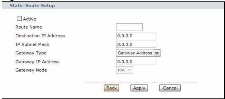
Figure 92 Advanced > Static Route: Edit
The following table describes the labels in this screen.
Table 59 Advanced > Static Route: Edit
| LABEL | DESCRIPTION |
| Active | This field allows you to activate/deactivate this static route. |
| Route Name | Enter the name of the IP static route. The text may consist of up to 9 letters, numerals and any printable character found on a typical English language keyboard. Leave this field blank to delete this static route. |
| Destination IP Address | This parameter specifies the IP network address of the final destination. Routing is always based on network number. If you need to specify a route to a single host, use a subnet mask of 255.255.255.255 in the subnet mask field to force the network number to be identical to the host ID. |
| IP Subnet Mask | Enter the IP subnet mask here. |
| Gateway Type | Use either Gateway Address or Gateway Node to configure a static route. |
| Gateway IP Address | Enter the IP address of the gateway. The gateway is a router or switch on the same network segment as the device's LAN or WAN port. The gateway helps forward packets to their destinations. |
| Gateway Node | This field is available when you select Gateway Node from Gateway Type. Select a remote node to set the static route. A remote note is a connection point outside of the local area network. One example of a remote node is your connection to your ISP. |
| Back | Click this to return to the previous screen without saving. |
| Apply | Click this to save your changes. |
| Cancel | Click this to restore your previously saved settings. |
14.1 Overview
This chapter describes how to configure the 802.1Q/1P settings.
A Virtual Local Area Network (VLAN) allows a physical network to be partitioned into multiple logical networks. A VLAN group can be treated as an individual device. Each group can have its own rules about where and how to forward traffic. You can assign any ports on the P-793H v2 to a VLAN group and configure the settings for the group. You may also set the priority level for traffic transmitted through the ports.
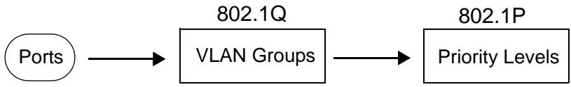
Figure 93 802.1Q/1P
14.1.1 What You Can Do in the 802.1Q/1P Screens
- Use the Group Setting screen (Section 14.2 on page 213) to activate 802.1Q/1P, specify the management VLAN group, display the VLAN groups and configure the settings for each VLAN group.
- Use the Port Setting screen (Section 14.3 on page 215) to configure the PVID and assign traffic priority for each port.
14.1.2 What You Need to Know About 802.1Q/1P
IEEE 802.1P Priority
IEEE 802.1P specifies the user priority field and defines up to eight separate traffic types by inserting a tag into a MAC-layer frame that contains bits to define class of service.
IEEE 802.1Q Tagged VLAN
Tagged VLAN uses an explicit tag (VLAN ID) in the MAC header to identify the VLAN membership of a frame across bridges - they are not confined to the device on which they were created. The VLAN ID associates a frame with a specific VLAN and provides the information that devices need to process the frame across the network.
PVC
A virtual circuit is a logical point-to-point circuit between customer sites.
Permanent means that the circuit is preprogrammed by the carrier as a path through the network. It does not need to be set up or torn down for each session.
Forwarding Tagged and Untagged Frames
Each port on the device is capable of passing tagged or untagged frames. To forward a frame from an 802.1Q VLAN-aware device to an 802.1Q VLAN-unaware device, the P-793H v2 first decides where to forward the frame and then strips off the VLAN tag. To forward a frame from an 802.1Q VLAN-unaware device to an 802.1Q VLAN-aware switch, the P-793H v2 first decides where to forward the frame, and then inserts a VLAN tag reflecting the ingress port's default VID. The default PVID is VLAN 1 for all ports, but this can be changed.
Whether to tag an outgoing frame depends on the setting of the egress port on a per-VLAN, per-port basis (recall that a port can belong to multiple VLANs). If the tagging on the egress port is enabled for the VID of a frame, then the frame is transmitted as a tagged frame; otherwise, it is transmitted as an untagged frame.
14.1.3 802.1Q/1P Example
This example shows how to configure the 802.1Q/1P settings on the P-793H v2.
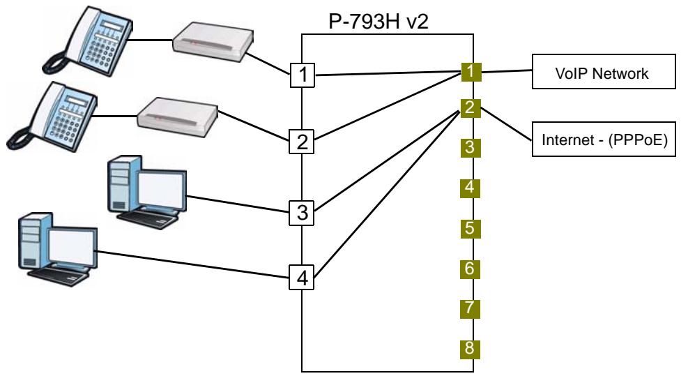
LAN1 and LAN2 are connected to ATAs (Analogue Telephone Adapters) and used for VoIP traffic. You want to create high priority for this type of traffic, so you want to group these ports into one VLAN (VLAN2) and then to a PVC (PVC1) where the priority is set to high level of service.
You would start with the following steps.
1 Click Advanced > 802.1Q/1P > Group Setting, and then click the Edit button to display the following screen.
2 In the Name field type VoIP to identify the group.
3 In the VLAN ID field type in 2 to identify the VLAN group.
4 Select PVC1 from the Default Gateway drop-down list box.
5 In the Control field, select Fixed for LAN1, LAN2 and PVC1 to be permanent members of the VLAN group.
6 Click Apply.
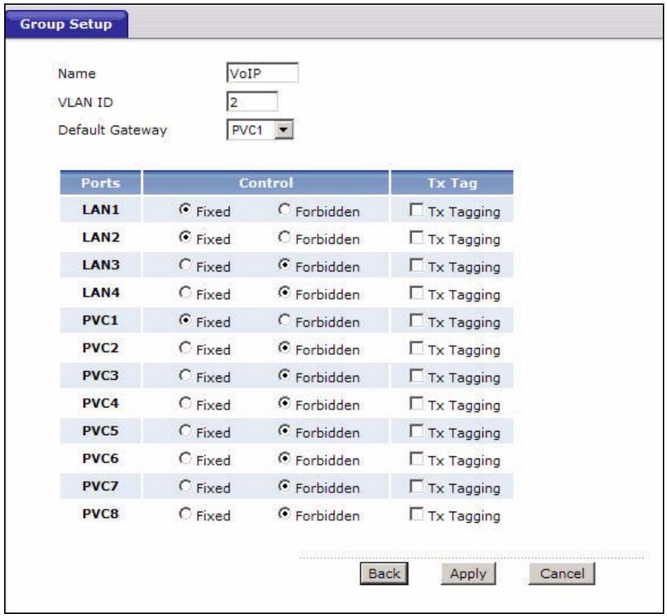
To set a high priority for VoIP traffic, follow these steps.
1 Click Advanced > 802.1Q/1P > Port Setting to display the following screen.
2 Type 2 in the 802.1Q PVID column for LAN1, LAN2 and PVC1.
3 Select 7 from the 802.1P Priority drop-down list box for LAN1, LAN2 and PVC1.
4 Click Apply.
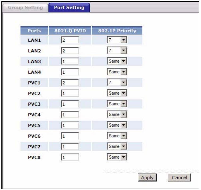
Ports 3 and 4 are connected to desktop computers and are used for Internet traffic. You want to create low priority for this type of traffic, so you want to group these ports and PVC2 into one VLAN (VLAN3). PVC2 priority is set to low level of service.
Follow the same steps as in VLAN2 to configure the settings for VLAN3. The summary screen should then display as follows.
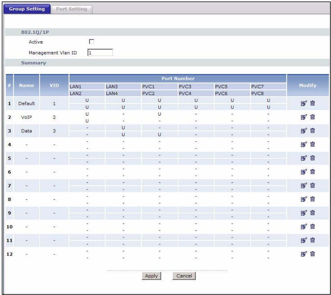
This completes the 802.1Q/1P setup.
14.2 The 802.1Q/1P Group Setting Screen
Use this screen to activate 802.1Q/1P and display the VLAN groups. Click
Advanced > 802.1Q/1P to display the following screen.
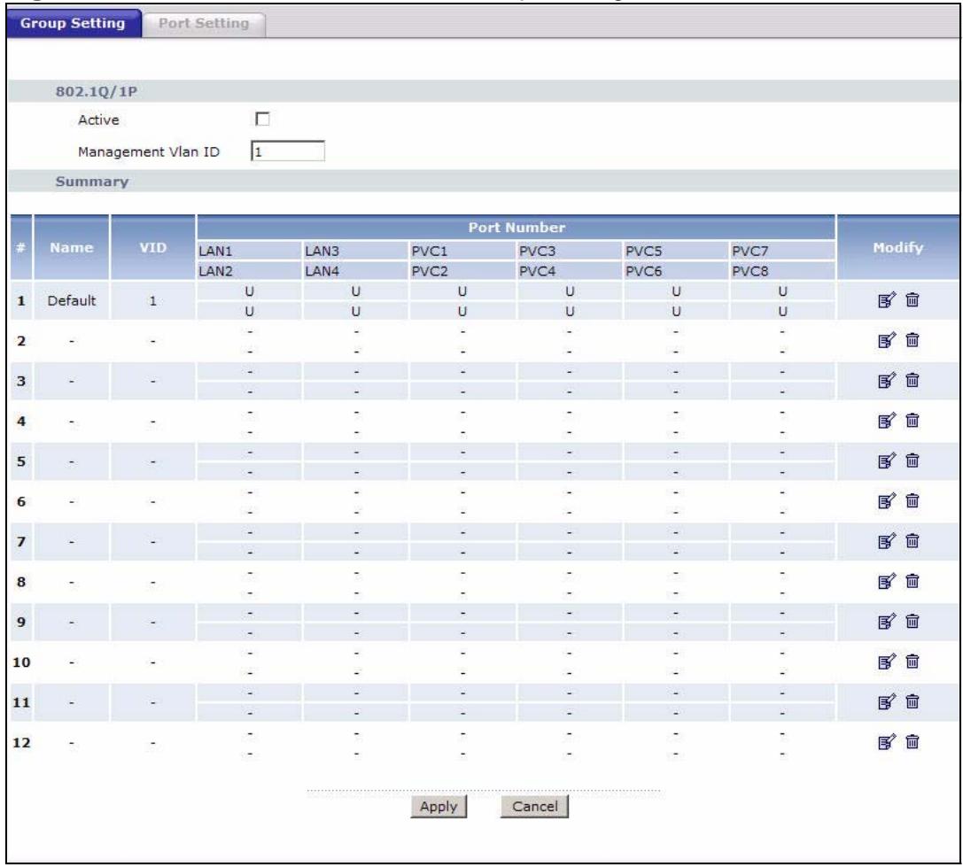
Figure 94 Advanced > 802.1Q/1P > Group Setting
The following table describes the labels in this screen.
Table 60 Advanced > 802.1Q/1P > Group Setting
| LABEL | DESCRIPTION |
| 802.1Q/1P | |
| Active | Select this check box to activate the 802.1P/1Q feature. |
| Management VLAN ID | Enter the ID number of a VLAN group. All interfaces (ports, SSIDs and PVCs) are in the management VLAN by default. If you disable the management VLAN, you will not be able to access the P-793H v2. |
| Summary | |
| # | This field displays the index number of the VLAN group. |
| Name | This field displays the name of the VLAN group. |
| VID | This field displays the ID number of the VLAN group. |
| Port Number | These columns display the VLAN's settings for each port. A tagged port is marked as T, an untagged port is marked as U and ports not participating in a VLAN are marked as “-”. |
| Modify | Click the Edit button to configure the ports in the VLAN group. Click the Remove button to delete the VLAN group. |
| Apply | Click this to save your changes. |
| Cancel | Click this to restore your previously saved settings. |
14.2.1 Editing 802.1Q/1P Group Setting
Use this screen to configure the settings for each VLAN group.
In the 802.1Q/1P screen, click the Edit button from the Modify filed to display the following screen.
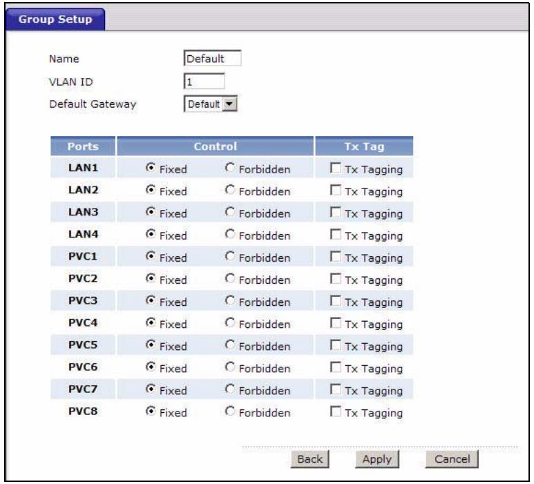
Figure 95 Advanced > 802.1Q/1P > Group Setting > Edit
The following table describes the labels in this screen.
Table 61 Advanced > 802.1Q/1P > Group Setting > Edit
| LABEL | DESCRIPTION |
| Name | Enter a descriptive name for the VLAN group for identification purposes. The text may consist of up to 8 letters, numerals, “-”, “_” and “@”. |
| VLAN ID | Assign a VLAN ID for the VLAN group. The valid VID range is between 1 and 4094. |
| Default Gateway | Select the default gateway for the VLAN group. |
| Ports | This field displays the types of ports available to join the VLAN group. |
| Control | Select Fixed for the port to be a permanent member of the VLAN group. Select Forbidden if you want to prohibit the port from joining the VLAN group. |
| Tx Tag | Select Tx Tagging if you want the port to tag all outgoing traffic transmitted through this VLAN. You select this if you want to create VLANs across different devices and not just the P-793H v2. |
| Back | Click this to return to the previous screen without saving. |
| Apply | Click this to save your changes. |
| Cancel | Click this to restore your previously saved settings. |
14.3 The 802.1Q/1P Port Setting Screen
Use this screen to configure the PVID and assign traffic priority for each port. Click Advanced > 802.1Q/1P > Port Setting to display the following screen.
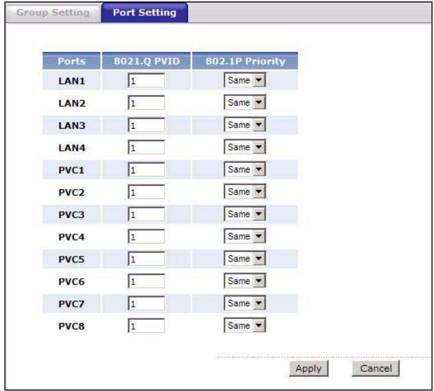
Figure 96 Advanced > 802.1Q/1P > Port Setting
The following table describes the labels in this screen.
Table 62 Advanced > 802.1Q/1P > Port Setting
| LABEL | DESCRIPTION |
| Ports | This field displays the types of ports available to join the VLAN group. |
| 802.1Q PVID | Assign a VLAN ID for the port. The valid VID range is between 1 and 4094. The P-793H v2 assigns the PVID to untagged frames or priority-tagged frames received on this port. |
| 802.1P Priority | Assign a priority for the traffic transmitted through the port. Select Same if you do not want to modify the priority. You may choose a priority level from 0-7, with 0 being the lowest level and 7 being the highest level. |
| Apply | Click this to save your changes. |
| Cancel | Click this to restore your previously saved settings. |
Quality of Service (QoS)
15.1 Overview
Use the QoS screens to set up your P-793H v2 to use QoS for traffic management.
Quality of Service (QoS) refers to both a network's ability to deliver data with minimum delay, and the networking methods used to control bandwidth. QoS allows the P-793H v2 to group and prioritize application traffic and fine-tune network performance.
Without QoS, all traffic data are equally likely to be dropped when the network is congested. This can cause a reduction in network performance and make the network inadequate for time-critical applications such as video-on-demand.
The P-793H v2 assigns each packet a priority and then queues the packet accordingly. Packets assigned with a high priority are processed more quickly than those with low priorities if there is congestion, allowing time-sensitive applications to flow more smoothly. Time-sensitive applications include both those that require a low level of latency (delay) and a low level of jitter (variations in delay) such as Voice over IP (VoIP) or Internet gaming, and those for which jitter alone is a problem such as Internet radio or streaming video.
15.2 QoS Overview
The following figure gives an overview of how to configure QoS on this P-793H v2:
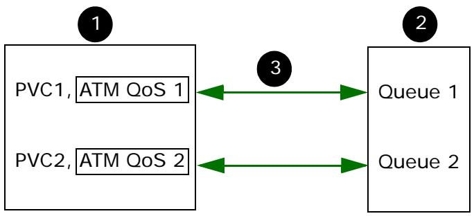
1 First, you have to configure WAN connection(s) in Network > WAN > Internet Access Setup and Network > WAN > More Connections. Click the Advanced Setup button on the corresponding PVC setting screens to configure ATM QoS, if you want to prioritize traffic and eliminate congestion over the ATM network (at the ATM layer).
2 Configure queue settings in Advanced > QoS > Queue Setup according to the priority you want to apply to different types of traffic.
3 Configure class settings in Advanced > QoS > Class Setup. This associates queues with PVCs by mapping the priority of queues to the index number of PVCs.
15.2.1 What You Can Do in the QoS Screens
- Use the General screen (Section 15.3 on page 223) to enable QoS on the P793H v2, decide allowable bandwidth using QoS and configure priority mapping settings for traffic that does not match a custom class.
- Use the Class Setup screen (Section 15.4 on page 224) to set up classifiers to sort traffic into different flows and assign priority and define actions to be performed for a classified traffic flow.
- Use the Monitor screen (Section 15.5 on page 230) to view the P-793H v2's QoS-related packet statistics.
15.2.2 What You Need to Know About QoS
QoS versus Cos
QoS is used to prioritize source-to-destination traffic flows. All packets in the same flow are given the same priority. Class of Service (CoS) is a way of managing traffic in a network by grouping similar types of traffic together and treating each type as a class. You can use CoS to give different priorities to different packet types.
CoS technologies include IEEE 802.1p layer 2 tagging and Differentiated Services (DiffServ or DS). IEEE 802.1p tagging makes use of three bits in the packet header, while DiffServ is a new protocol and defines a new DS field, which replaces the eight-bit Type of Service (ToS) field in the IP header.
Tagging and Marking
In a QoS class, you can configure whether to add or change the DiffServ Code Point (DSCP) value, IEEE 802.1p priority level and VLAN ID number in a matched packet. When the packet passes through a compatible network, the networking device, such as a backbone switch, can provide specific treatment or service based on the tag or marker.
Finding Out More
See Section 15.6 on page 231 for advanced technical information on QoS.
15.2.3 QoS Class Setup Example
In the following figure, your Internet connection has an upstream transmission speed of 50 Mbps. You configure a classifier to assign the highest priority queue (6) to VoIP traffic from the LAN interface, so that voice traffic would not get delayed when there is network congestion. Traffic from the boss's IP address (192.168.1.23 for example) is mapped to queue 5. Traffic that does not match
these two classes are assigned priority queue based on the internal QoS mapping table on the P-793H v2.
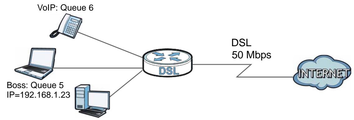
Figure 97 QoS Example
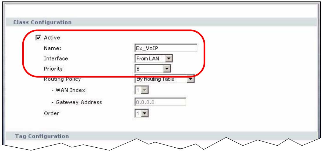
Figure 98 QoS Class Example: VoIP -1
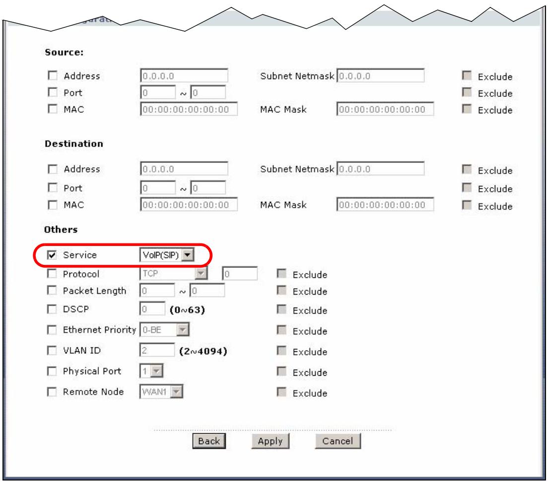
Figure 99 QoS Class Example: VoIP -2
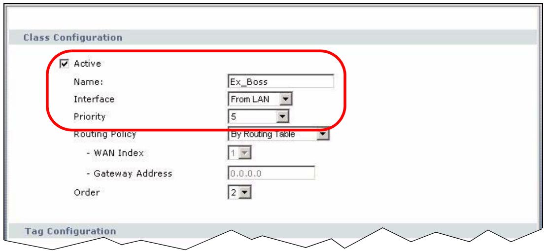
Figure 100 QoS Class Example: Boss -1
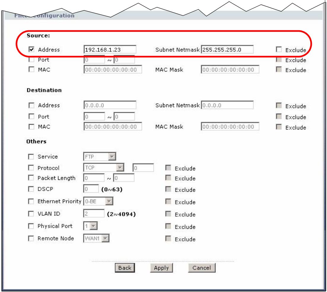
Figure 101 QoS Class Example: Boss -2
15.3 The QoS General Screen
Use this screen to enable or disable QoS and have the P-793H v2 automatically assign priority to traffic according to the IEEE 802.1p priority level, IP precedence and/or packet length.
Click Advanced > QoS to open the screen as shown next.
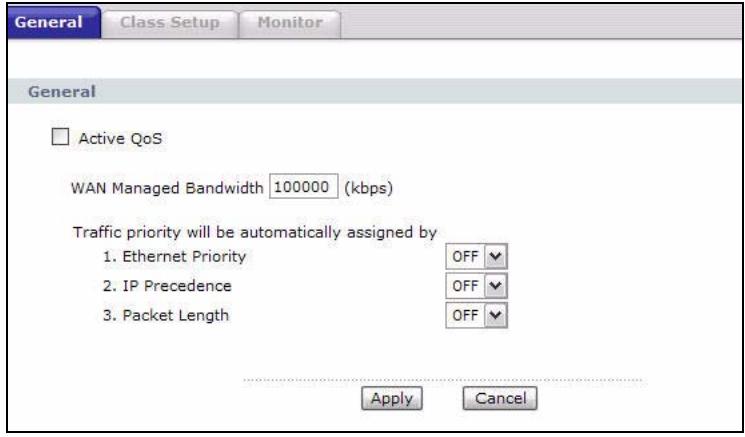
Figure 102 Advanced > QoS > General
The following table describes the labels in this screen.
Table 63 Advanced > QoS > General
| LABEL | DESCRIPTION |
| Active QoS | Select the check box to turn on QoS to improve your network performance. You can give priority to traffic that the P-793H v2 forwards out through the WAN interface. Give high priority to voice and video to make them run more smoothly. Similarly, give low priority to many large file downloads so that they do not reduce the quality of other applications. |
| WAN Managed Bandwidth | Enter the amount of bandwidth for the WAN interface that you want to allocate using QoS. The recommendation is to set this speed to match the interface's actual transmission speed. For example, set the WAN interface speed to 100000 kbps if your Internet connection has an upstream transmission speed of 100 Mbps. You can set this number higher than the interface's actual transmission speed. This will stop lower priority traffic from being sent if higher priority traffic uses all of the actual bandwidth. You can also set this number lower than the interface's actual transmission speed. This will cause the P-793H v2 to not use some of the interface's available bandwidth. |
Table 63 Advanced > QoS > General
| LABEL | DESCRIPTION |
| Traffic priority will be automatically assigned by | These fields are ignored if traffic matches a class you configured in the Class Setup screen.If you select ON and traffic does not match a class configured in the Class Setup screen, the P-793H v2 assigns priority to unmatched traffic based on the IEEE 802.1p priority level, IP precedence and/or packet length. See Section 15.6.4 on page 232 for more information.If you select OFF, traffic which does not match a class is mapped to queue two. |
| Apply | Click this to save your changes. |
| Cancel | Click this to restore your previously saved settings. |
15.4 The Class Setup Screen
Use this screen to add, edit or delete classifiers. A classifier groups traffic into data flows according to specific criteria such as the source address, destination address, source port number, destination port number or incoming interface. For example, you can configure a classifier to select traffic from the same protocol port (such as Telnet) to form a flow.
Click Advanced > QoS > Class Setup to open the following screen.
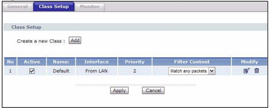
Figure 103 Advanced > QoS > Class Setup
The following table describes the labels in this screen.
Table 64 Advanced > QoS > Class Setup
| LABEL | DESCRIPTION |
| Create a new Class | Click Add to create a new classifier. |
| No | This is the number of each classifier. The ordering of the classifiers is important as the classifiers are applied in turn. |
| Active | Select the check box to enable this classifier. |
| Name | This is the name of the classifier. |
| Interface | This shows the interface from which traffic of this classifier should come. |
| Priority | This is the priority assigned to traffic of this classifier. |
| Filter Content | This shows criteria specified in this classifier. |
| Modify | Click the Edit icon to go to the screen where you can edit the classifier. Click the Remove icon to delete an existing classifier. |
| Apply | Click this to save your changes. |
| Cancel | Click this to restore your previously saved settings. |
15.4.1 The Class Configuration Screen
Use this screen to configure a classifier. Click the Add button or the Edit icon in the Modify field to display the following screen.
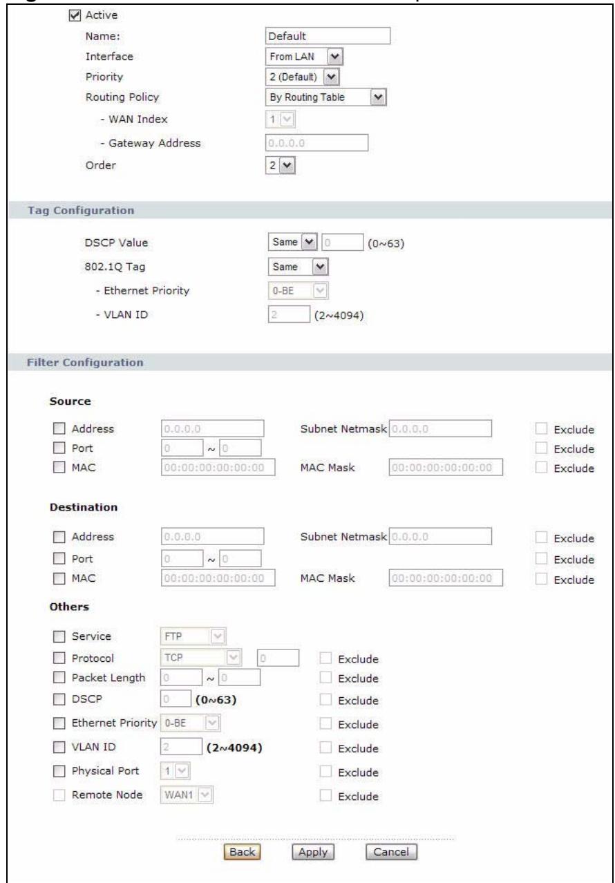
Figure 104 Advanced > QoS > Class Setup: Edit
See Appendix F on page 473 for a list of commonly-used services. The following table describes the labels in this screen.
Table 65 Advanced > QoS > Class Setup: Edit
| LABEL | DESCRIPTION |
| Class Configuration | |
| Active | Select the check box to enable this classifier. |
| Name | The text may consist of up to 20 letters, numerals and any printable character found on a typical English language keyboard. |
| Interface | Select from which interface traffic of this class should come. |
| Priority | Select a priority level (between 0 and 7) or select Auto to have the P-793H v2 map the matched traffic to a queue according to the internal QoS mapping table. See Section 15.6.4 on page 232 for more information. "0" is the lowest priority level and "7" is the highest. |
| Routing Policy | Select the next hop to which traffic of this class should be forwarded. Select By Routing Table to have the P-793H v2 use the routing table to find a next hop and forward the matched packets automatically. Select To WAN Index to route the matched packets through the specified PVC. This option is available only when the WAN type is ADSL. Select To Gateway Address to route the matched packets to the router or switch you specified in the Gateway Address field. |
| WAN Index | Select a PVC index number. |
| Gateway Address | Enter the IP address of the gateway, which should be a router or switch on the same segment as the P-793H v2's interface(s), that can forward the packet to the destination. |
| Order | This shows the ordering number of this classifier. Select an existing number for where you want to put this classifier and click Apply to move the classifier to the number you selected. For example, if you select 2, the classifier you are moving becomes number 2 and the previous classifier 2 gets pushed down one. |
| Tag Configuration | |
| DSCP Value | Select Same to keep the DSCP fields in the packets. Select Auto to map the DSCP value to 802.1 priority level automatically. Select Mark to set the DSCP field with the value you configure in the field provided. |
| 802.1Q Tag | Select Same to keep the priority setting and VLAN ID of the frames. Select Auto to map the 802.1 priority level to the DSCP value automatically. Select Remove to delete the priority queue tag and VLAN ID of the frames. Select Mark to replace the 802.1 priority field and VLAN ID with the value you set in the fields below. Select Add to treat all matched traffic untagged and add a second priority queue tag and VLAN. |
| Ethernet Priority | Select a priority level (between 0 and 7) from the drop down list box. |
| VLAN ID | Specify a VLAN ID number between 2 and 4094. |
| Filter Configuration | Use the following fields to configure the criteria for traffic classification. |
| Source | |
| Address | Select the check box and enter the source IP address in dotted decimal notation. A blank source IP address means any source IP address. |
| Subnet Netmask | Enter the source subnet mask. Refer to the appendix for more information on IP subnetting. |
| Port | Select the check box and enter the port number of the source. 0 means any source port number. See Appendix F on page 473 for some common services and port numbers. |
| MAC | Select the check box and enter the source MAC address of the packet. |
| MAC Mask | Type the mask for the specified MAC address to determine which bits a packet's MAC address should match. Enter "f" for each bit of the specified source MAC address that the traffic's MAC address should match. Enter "0" for the bit(s) of the matched traffic's MAC address, which can be of any hexadecimal character(s). For example, if you set the MAC address to 00:13:49:00:00:00 and the mask to ff:ff:ff:00:00:00, a packet with a MAC address of 00:13:49:12:34:56 matches this criteria. |
| Exclude | Select this option to exclude the packets that match the specified criteria from this classifier. |
| Destination | |
| Address | Select the check box and enter the destination IP address in dotted decimal notation. |
| Subnet Netmask | Enter the destination subnet mask. Refer to the appendix for more information on IP subnetting. |
| Port | Select the check box and enter the port number of the destination. 0 means any source port number. See Appendix F on page 473 for some common services and port numbers. |
| MAC | Select the check box and enter the destination MAC address of the packet. |
| MAC Mask | Type the mask for the specified MAC address to determine which bits a packet's MAC address should match. Enter "f" for each bit of the specified destination MAC address that the traffic's MAC address should match. Enter "0" for the bit(s) of the matched traffic's MAC address, which can be of any hexadecimal character(s). For example, if you set the MAC address to 00:13:49:00:00 and the mask to ff:ff:ff:00:00, a packet with a MAC address of 00:13:49:12:34:56 matches this criteria. |
| Exclude | Select this option to exclude the packets that match the specified criteria from this classifier. |
| Others | |
| Service | This field simplifies classifier configuration by allowing you to select a predefined application. When you select a predefined application, you do not configure the rest of the filter fields. SIP (Session Initiation Protocol) is a signaling protocol used in Internet telephony, instant messaging and other VoIP (Voice over IP) applications. Select the check box and select VoIP(SIP) from the drop-down list box to configure this classifier for traffic that uses SIP. File Transfer Protocol (FTP) is an Internet file transfer service that operates on the Internet and over TCP/IP networks. A system running the FTP server accepts commands from a system running an FTP client. The service allows users to send commands to the server for uploading and downloading files. Select the check box and select FTP from the drop-down list box to configure this classifier for FTP traffic. |
| Protocol | Select this option and select the protocol (TCP or UDP) or select User defined and enter the protocol (service type) number. 0 means any protocol number. |
| Packet Length | Select this option and enter the minimum and maximum packet length (from 28 to 1500) in the fields provided. |
| DSCP | Select this option and specify a DSCP (DiffServ Code Point) number between 0 and 63 in the field provided. |
| Ethernet Priority | Select this option and select a priority level (between 0 and 7) from the drop down list box. "0" is the lowest priority level and "7" is the highest. |
| VLAN ID | Select this option and specify a VLAN ID number between 2 and 4094. |
| Physical Port | Select this option and select a LAN port. |
| Remote Node | Select this option and select a remote node from the drop down list box. When the WAN type is Ethernet in the WAN > Internet Access Setup screen, you can select WAN1 only. |
| Exclude | Select this option to exclude the packets that match the specified criteria from this classifier. |
| Back | Click this to return to the previous screen without saving. |
| Apply | Click this to save your changes. |
| Cancel | Click this to restore your previously saved settings. |
15.5 The QoS Monitor Screen
Use this screen to view the P-793H v2's QoS packet statistics. Click Advanced > QoS > Monitor. The screen appears as shown.
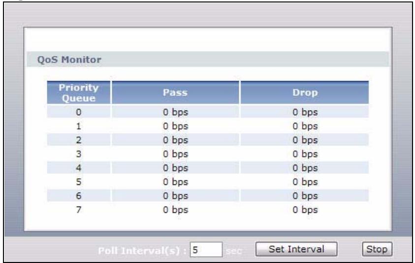
Figure 105 Advanced > QoS > Monitor
The following table describes the labels in this screen.
Table 66 Advanced > QoS > Monitor
| LABEL | DESCRIPTION |
| Priority Queue | This shows the priority queue number.Traffic assigned to higher index queues gets through faster while traffic in lower index queues is dropped if the network is congested. |
| Pass | This shows how many packets mapped to this priority queue are transmitted successfully. |
| Drop | This shows how many packets mapped to this priority queue are dropped. |
| Poll Interval(s) | Enter the time interval for refreshing statistics in this field. |
| Set Interval | Click this to apply the new poll interval you entered in the Poll Interval(s) field. |
| Stop | Click this to stop refreshing statistics. |
15.6 QoS Technical Reference
This section provides some technical background information about the topics covered in this chapter.
15.6.1 IEEE 802.1Q Tag
The IEEE 802.1Q standard defines an explicit VLAN tag in the MAC header to identify the VLAN membership of a frame across bridges. A VLAN tag includes the 12-bit VLAN ID and 3-bit user priority. The VLAN ID associates a frame with a specific VLAN and provides the information that devices need to process the frame across the network.
IEEE 802.1p specifies the user priority field and defines up to eight separate traffic types. The following table describes the traffic types defined in the IEEE 802.1d standard (which incorporates the 802.1p).
Table 67 IEEE 802.1p Priority Level and Traffic Type
| PRIORITY LEVEL | TRAFFIC TYPE |
| Level 7 | Typically used for network control traffic such as router configuration messages. |
| Level 6 | Typically used for voice traffic that is especially sensitive to jitter (jitter is the variations in delay). |
| Level 5 | Typically used for video that consumes high bandwidth and is sensitive to jitter. |
| Level 4 | Typically used for controlled load, latency-sensitive traffic such as SNA (Systems Network Architecture) transactions. |
| Level 3 | Typically used for “excellent effort” or better than best effort and would include important business traffic that can tolerate some delay. |
| Level 2 | This is for “spare bandwidth”. |
| Level 1 | This is typically used for non-critical “background” traffic such as bulk transfers that are allowed but that should not affect other applications and users. |
| Level 0 | Typically used for best-effort traffic. |
15.6.2 IP Precedence
Similar to IEEE 802.1p prioritization at layer-2, you can use IP precedence to prioritize packets in a layer-3 network. IP precedence uses three bits of the eight-bit ToS (Type of Service) field in the IP header. There are eight classes of services (ranging from zero to seven) in IP precedence. Zero is the lowest priority level and seven is the highest.
15.6.3 DiffServ
QoS is used to prioritize source-to-destination traffic flows. All packets in the flow are given the same priority. You can use CoS (class of service) to give different priorities to different packet types.
Differentiated Services (DiffServ) is a Class of Service (CoS) model that marks packets so that they receive specific per-hop treatment at DiffServ-compliant network devices along the route based on the application types and traffic flow. Packets are marked with DiffServ Code Points (DSCPs) indicating the level of service desired. This allows the intermediary DiffServ-compliant network devices to handle the packets differently depending on the code points without the need to negotiate paths or remember state information for every flow. In addition, applications do not have to request a particular service or give advanced notice of where the traffic is going.
DSCP and Per-Hop Behavior
DiffServ defines a new Differentiated Services (DS) field to replace the Type of Service (TOS) field in the IP header. The DS field contains a 2-bit unused field and a 6-bit DSCP field which can define up to 64 service levels. The following figure illustrates the DS field.
DSCP is backward compatible with the three precedence bits in the ToS octet so that non-DiffServ compliant, ToS-enabled network device will not conflict with the DSCP mapping.
DSCP (6 bits)
Unused (2 bits)
The DSCP value determines the forwarding behavior, the PHB (Per-Hop Behavior), that each packet gets across the DiffServ network. Based on the marking rule, different kinds of traffic can be marked for different kinds of forwarding. Resources can then be allocated according to the DSCP values and the configured policies.
15.6.4 Automatic Priority Queue Assignment
If you enable QoS on the P-793H v2, the P-793H v2 can automatically base on the IEEE 802.1p priority level, IP precedence and/or packet length to assign priority to traffic which does not match a class.
The following table shows you the internal layer-2 and layer-3 QoS mapping on the P-793H v2. On the P-793H v2, traffic assigned to higher priority queues gets
through faster while traffic in lower index queues is dropped if the network is congested.
Table 68 Internal Layer2 and Layer3 QoS Mapping
| PRIORITY QUEUE | LAYER 2 | LAYER 3 | ||
| IEEE 802.1P USER PRIORITY (ETHERNET PRIORITY) | TOS (IP PRECEDENCE) | DSCP | IP PACKET LENGTH (BYTE) | |
| 0 | 1 | 0 | 000000 | |
| 1 | 2 | |||
| 2 | 0 | 0 | 000000 | >1100 |
| 3 | 3 | 1 | 001110 | 250~1100 |
| 001100 | ||||
| 001010 | ||||
| 001000 | ||||
| 4 | 4 | 2 | 010110 | |
| 010100 | ||||
| 010010 | ||||
| 010000 | ||||
| 5 | 5 | 3 | 011110 | <250 |
| 011100 | ||||
| 011010 | ||||
| 011000 | ||||
| 6 | 6 | 4 | 100110 | |
| 100100 | ||||
| 100010 | ||||
| 100000 | ||||
| 5 | 101110 | |||
| 101000 | ||||
| 7 | 7 | 6 | 110000 | |
| 7 | 111000 | |||
Dynamic DNS Setup
16.1 Overview
Dynamic DNS allows you to update your current dynamic IP address with one or many dynamic DNS services so that anyone can contact you (in NetMeeting, CU-SeeMe, etc.). You can also access your FTP server or Web site on your own computer using a domain name (for instance myhost.dhs.org, where myhost is a name of your choice) that will never change instead of using an IP address that changes each time you reconnect. Your friends or relatives will always be able to call you even if they don't know your IP address.
First of all, you need to have registered a dynamic DNS account with www.dyndns.org. This is for people with a dynamic IP from their ISP or DHCP server that would still like to have a domain name. The Dynamic DNS service provider will give you a password or key.
16.1.1 What You Need To Know About DDNS
DYNDNS Wildcard
Enabling the wildcard feature for your host causes *.yourhost.dyndns.org to be aliased to the same IP address as yourhost.dyndns.org. This feature is useful if you want to be able to use, for example, www.yourhost.dyndns.org and still reach your hostname.
If you have a private WAN IP address, then you cannot use Dynamic DNS.
16.2 The Dynamic DNS Screen
Use this screen to change your P-793H v2's DDNS. Click Advanced > Dynamic DNS. The screen appears as shown.
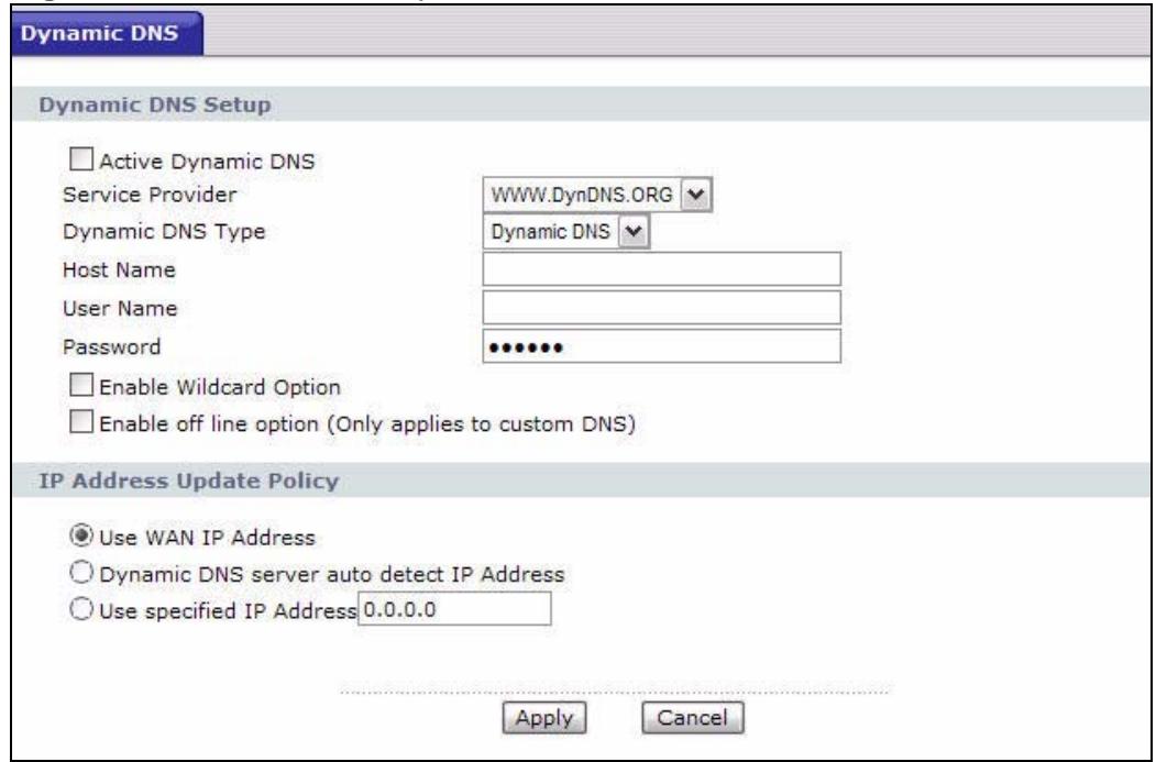
Figure 106 Advanced > Dynamic DNS
The following table describes the fields in this screen.
Table 69 Advanced > Dynamic DNS
| LABEL | DESCRIPTION |
| Dynamic DNS Setup | |
| Active Dynamic DNS | Select this check box to use dynamic DNS. |
| Service Provider | This is the name of your Dynamic DNS service provider. |
| Dynamic DNS Type | Select the type of service that you are registered for from your Dynamic DNS service provider. |
| Host Name | Type the domain name assigned to your P-793H v2 by your Dynamic DNS provider. You can specify up to two host names in the field separated by a comma (" , ") . |
| User Name | Type your user name. |
| Password | Type the password assigned to you. |
| Enable Wildcard Option | Select the check box to enable DynDNS Wildcard. |
| Enable off line option | This option is available when CustomDNS is selected in the DDNS Type field. Check with your Dynamic DNS service provider to have traffic redirected to a URL (that you can specify) while you are off line. |
| IP Address Update Policy | |
| Use WAN IP Address | Select this option to update the IP address of the host name(s) to the WAN IP address. |
| Dynamic DNS server auto detect IP Address | Select this option only when there are one or more NAT routers between the P-793H v2 and the DDNS server. This feature has the DDNS server automatically detect and use the IP address of the NAT router that has a public IP address.Note: The DDNS server may not be able to detect the proper IP address if there is an HTTP proxy server between the P-793H v2 and the DDNS server. |
| Use specified IP Address | Type the IP address of the host name(s). Use this if you have a static IP address. |
| Apply | Click this to save your changes. |
| Cancel | Click this to restore your previously saved settings. |
Remote Management
17.1 Overview
Remote management allows you to determine which services/protocols can access which P-793H v2 interface (if any) from which computers.
The following figure shows remote management of the P-793H v2 coming in from the WAN.
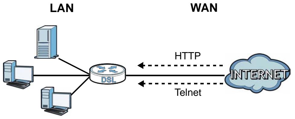
Figure 107 Remote Management From the WAN
Note: When you configure remote management to allow management from the WAN, you still need to configure a firewall rule to allow access.
You may manage your P-793H v2 from a remote location via:
- Internet (WAN only)
- LAN only
- ALL (WAN and LAN)
- None (Disable)
To disable remote management of a service, select Disable in the corresponding Access Status field.
You may only have one remote management session running at a time. The P-793H v2 automatically disconnects a remote management session of lower priority when another remote management session of higher priority starts. The priorities for the different types of remote management sessions are as follows.
1 Telnet
2 HTTP
17.1.1 What You Can Do in the Remote Management Screens
- Use the WWW screen (Section 17.2 on page 241) to configure through which interface(s) and from which IP address(es) users can use HTTP to manage the P-793H v2.
- Use the Telnet screen (Section 17.3 on page 242) to configure through which interface(s) and from which IP address(es) users can use Telnet to manage the P-793H v2.
- Use the FTP screen (Section 17.4 on page 243) to configure through which interface(s) and from which IP address(es) users can use FTP to access the P-793H v2.
- Use the SNMP screen (Section 17.5 on page 248) to configure your P-793H v2's settings for Simple Network Management Protocol management.
- Use the DNS screen (Section 17.6 on page 248) to configure through which interface(s) and from which IP address(es) users can send DNS queries to the P-793H v2.
- Use the ICMP screen (Section 17.7 on page 249) to set whether or not your P-793H v2 will respond to pings and probes for services that you have not made available.
17.1.2 What You Need to Know About Remote Management
Remote Management Limitations
Remote management does not work when:
- You have not enabled that service on the interface in the corresponding remote management screen.
- You have disabled that service in one of the remote management screens.
-
The IP address in the Secured Client IP field does not match the client IP address. If it does not match, the P-793H v2 will disconnect the session immediately.
-
There is already another remote management session with an equal or higher priority running. You may only have one remote management session running at one time.
- There is a firewall rule that blocks it.
Remote Management and NAT
When NAT is enabled:
- Use the P-793H v2's WAN IP address when configuring from the WAN.
- Use the P-793H v2's LAN IP address when configuring from the LAN.
System Timeout
There is a default system management idle timeout of five minutes (three hundred seconds). The P-793H v2 automatically logs you out if the management session remains idle for longer than this timeout period. The management session does not time out when a statistics screen is polling.
17.2 The WWW Screen
Use this screen to specify how to connect to the P-793H v2 from a web browser, such as Internet Explorer. You can also specify which IP addresses the access can come from.
Note: If you disable the WWW service in this screen, then the P-793H v2 blocks all HTTP connection attempts.
17.2.1 Configuring the WWW Screen
Click Advanced > Remote MGMT to display the WWW screen.
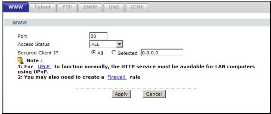
Figure 108 Advanced > Remote Management > WWW
The following table describes the labels in this screen.
Table 70 Advanced > Remote Management > WWW
| LABEL | DESCRIPTION |
| Port | You may change the server port number for a service, if needed. However, you must use the same port number in order to use that service for remote management. |
| Access Status | Select the interface(s) through which a computer may access the P-793H v2 using this service. |
| Secured Client IP | A secured client is a “trusted” computer that is allowed to communicate with the P-793H v2 using this service. Select All to allow any computer to access the P-793H v2 using this service. Choose Selected to just allow the computer with the IP address that you specify to access the P-793H v2 using this service. |
| Apply | Click this to save your changes. |
| Cancel | Click this to restore your previously saved settings. |
17.3 The Telnet Screen
You can use Telnet to access the P-793H v2's command line interface. Specify which interfaces allow Telnet access and from which IP address the access can come.
Click Advanced > Remote MGMT > Telnet tab to display the screen as shown.
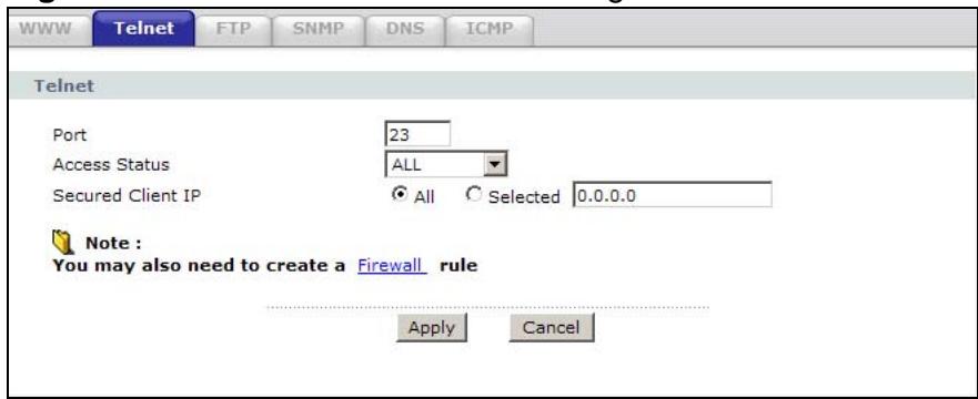
Figure 109 Advanced > Remote Management > Telnet
The following table describes the labels in this screen.
Table 71 Advanced > Remote Management > Telnet
| LABEL | DESCRIPTION |
| Port | You may change the server port number for a service if needed, however you must use the same port number in order to use that service for remote management. |
| Access Status | Select the interface(s) through which a computer may access the P-793H v2 using this service. |
| Secured Client IP | A secured client is a “trusted” computer that is allowed to communicate with the P-793H v2 using this service. Select All to allow any computer to access the P-793H v2 using this service. Choose Selected to just allow the computer with the IP address that you specify to access the P-793H v2 using this service. |
| Apply | Click this to save your changes. |
| Cancel | Click this to restore your previously saved settings. |
17.4 The FTP Screen
You can use FTP (File Transfer Protocol) to upload and download the P-793H v2's firmware and configuration files. Please see the User's Guide chapter on firmware and configuration file maintenance for details. To use this feature, your computer must have an FTP client.
Use this screen to specify which interfaces allow FTP access and from which IP address the access can come. To change your P-793H v2's FTP settings, click Advanced > Remote MGMT > FTP. The screen appears as shown.
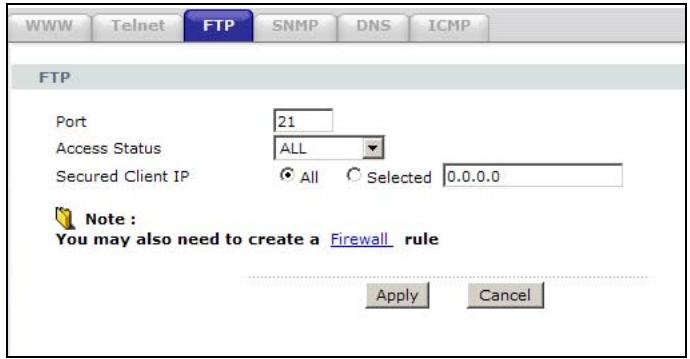
Figure 110 Advanced > Remote Management > FTP
The following table describes the labels in this screen.
Table 72 Advanced > Remote Management > FTP
| LABEL | DESCRIPTION |
| Port | You may change the server port number for a service, if needed. However, you must use the same port number in order to use that service for remote management. |
| Access Status | Select the interface(s) through which a computer may access the P-793H v2 using this service. |
| Secured Client IP | A secured client is a “trusted” computer that is allowed to communicate with the P-793H v2 using this service. Select All to allow any computer to access the P-793H v2 using this service. Choose Selected to just allow the computer with the IP address that you specify to access the P-793H v2 using this service. |
| Apply | Click this to save your changes. |
| Cancel | Click this to restore your previously saved settings. |
17.5 The SNMP Screen
Simple Network Management Protocol (SNMP) is a protocol used for exchanging management information between network devices. SNMP is a member of the TCP/IP protocol suite. Your P-793H v2 supports SNMP agent functionality, which allows a manager station to manage and monitor the P-793H v2 through the network. The P-793H v2 supports SNMP version one (SNMPv1) and version two (SNMPv2). The next figure illustrates an SNMP management operation.
Note: SNMP is only available if TCP/IP is configured.
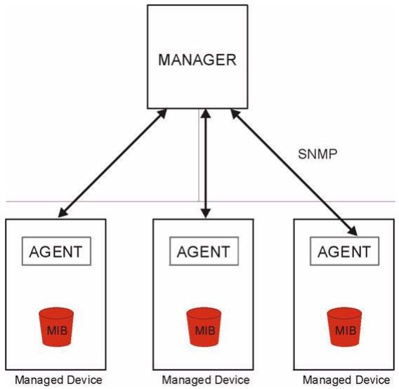
Figure 111 SNMP Management Model
An SNMP managed network consists of two main types of component: agents and a manager.
An agent is a management software module that resides in a managed device (the P-793H v2). An agent translates the local management information from the managed device into a form compatible with SNMP. The manager is the console through which network administrators perform network management functions. It executes applications that control and monitor managed devices.
The managed devices contain object variables/managed objects that define each piece of information to be collected about a device. Examples of variables include such as number of packets received, node port status etc. A Management Information Base (MIB) is a collection of managed objects. SNMP allows a manager and agents to communicate for the purpose of accessing these objects.
SNMP itself is a simple request/response protocol based on the manager/agent model. The manager issues a request and the agent returns responses using the following protocol operations:
- Get - Allows the manager to retrieve an object variable from the agent.
- GetNext - Allows the manager to retrieve the next object variable from a table or list within an agent. In SNMPv1, when a manager wants to retrieve all elements of a table from an agent, it initiates a Get operation, followed by a series of GetNext operations.
- Set - Allows the manager to set values for object variables within an agent
- Trap - Used by the agent to inform the manager of some events.
17.5.1 Supported MIBs
The P-793H v2 supports MIB II, which is defined in RFC-1213 and RFC-1215. The focus of the MIBs is to let administrators collect statistical data and monitor status and performance.
17.5.2 SNMP Traps
The P-793H v2 will send traps to the SNMP manager when any one of the following events occurs:
Table 73 SNMP Traps
| TRAP # | TRAP NAME | DESCRIPTION |
| 0 | coldStart (defined in RFC-1215) | A trap is sent after booting (power on). |
| 1 | warmStart (defined in RFC-1215) | A trap is sent after booting (software reboot). |
| 4 | authenticationFailure (defined in RFC-1215) | A trap is sent to the manager when receiving any SNMP get or set requirements with the wrong community (password). |
| 6 | whyReboot (defined in ZYXEL-MIB) | A trap is sent with the reason of restart before rebooting when the system is going to restart (warm start). |
| 6a | For intentional reboot: | A trap is sent with the message "System reboot by user!" if reboot is done intentionally, (for example, download new files, CI command "sys reboot", etc.). |
| 6b | For fatal error: | A trap is sent with the message of the fatal code if the system reboots because of fatal errors. |
17.5.3 Configuring SNMP
To change your P-793H v2's SNMP settings, click Advanced > Remote MGMT > SNMP. The screen appears as shown.
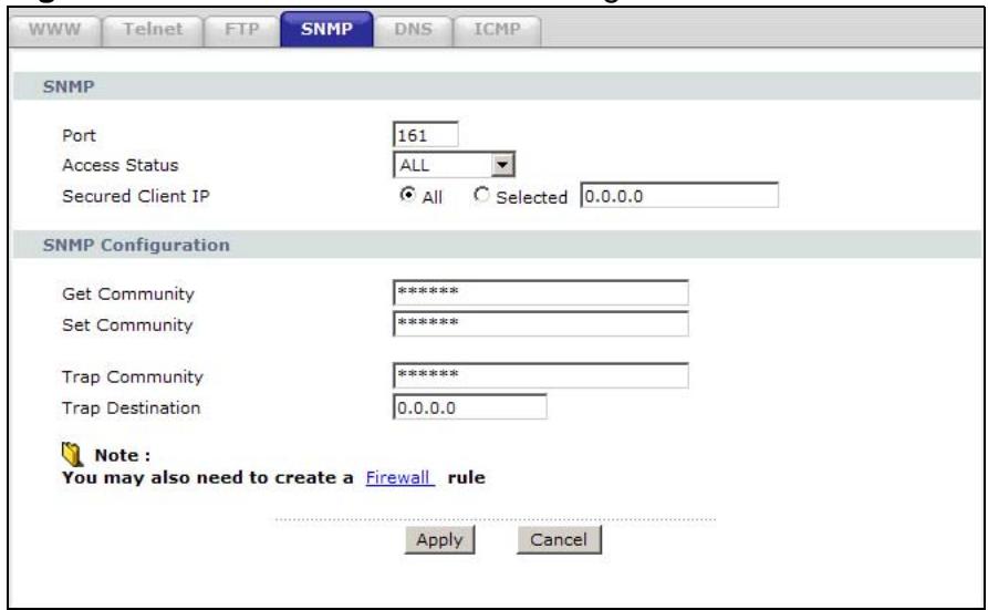
Figure 112 Advanced > Remote Management > SNMP
The following table describes the labels in this screen.
Table 74 Advanced > Remote Management > SNMP
| LABEL | DESCRIPTION |
| SNMP | |
| Port | You may change the server port number for a service, if needed. However, you must use the same port number in order to use that service for remote management. |
| Access Status | Select the interface(s) through which a computer may access the P-793H v2 using this service. |
| Secured Client IP | A secured client is a “trusted” computer that is allowed to communicate with the P-793H v2 using this service. Select All to allow any computer to access the P-793H v2 using this service. Choose Selected to just allow the computer with the IP address that you specify to access the P-793H v2 using this service. |
| SNMP Configuration | |
| Get Community | Enter the Get Community, which is the password for the incoming Get and GetNext requests from the management station. The default is public and allows all requests. |
| Set Community | Enter the Set community, which is the password for incoming Set requests from the management station. The default is public and allows all requests. |
| TrapCommunity | Type the trap community, which is the password sent with each trap to the SNMP manager. The default is public and allows all requests. |
| TrapDestination | Type the IP address of the station to send your SNMP traps to. |
Table 74 Advanced > Remote Management > SNMP
| LABEL | DESCRIPTION |
| Apply | Click this to save your changes. |
| Cancel | Click this to restore your previously saved settings. |
17.6 The DNS Screen
Use DNS (Domain Name System) to map a domain name to its corresponding IP address and vice versa. Refer to Chapter 7 on page 101 for background information.
Use this screen to set from which IP address the P-793H v2 will accept DNS queries and on which interface it can send them your P-793H v2's DNS settings. This feature is not available when the P-793H v2 is set to bridge mode. Click Advanced > Remote MGMT > DNS to change your P-793H v2's DNS settings.
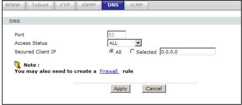
Figure 113 Advanced > Remote Management > DNS
The following table describes the labels in this screen.
Table 75 Advanced > Remote Management > DNS
| LABEL | DESCRIPTION |
| Port | The DNS service port number is 53 and cannot be changed here. |
| Access Status | Select the interface(s) through which a computer may send DNS queries to the P-793H v2. |
| Secured Client IP | A secured client is a “trusted” computer that is allowed to send DNS queries to the P-793H v2. Select All to allow any computer to send DNS queries to the P-793H v2. Choose Selected to just allow the computer with the IP address that you specify to send DNS queries to the P-793H v2. |
| Apply | Click this to save your changes. |
| Cancel | Click this to restore your previously saved settings. |
17.7 The ICMP Screen
To change your P-793H v2's security settings, click Advanced > Remote MGMT > ICMP. The screen appears as shown.
If an outside user attempts to probe an unsupported port on your P-793H v2, an ICMP response packet is automatically returned. This allows the outside user to know the P-793H v2 exists. Your P-793H v2 supports anti-probing, which prevents the ICMP response packet from being sent. This keeps outsiders from discovering your P-793H v2 when unsupported ports are probed.
Note: If you want your device to respond to pings and requests for unauthorized services, you may also need to configure the firewall anti probing settings to match.
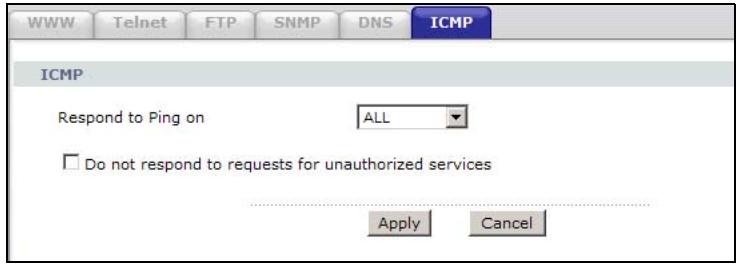
Figure 114 Advanced > Remote Management > ICMP
The following table describes the labels in this screen.
Table 76 Advanced > Remote Management > ICMP
| LABEL | DESCRIPTION |
| ICMP | Internet Control Message Protocol is a message control and error-reporting protocol between a host server and a gateway to the Internet. ICMP uses Internet Protocol (IP) datagrams, but the messages are processed by the TCP/IP software and directly apparent to the application user. |
| Respond to Ping on | The P-793H v2 will not respond to any incoming Ping requests when Disable is selected. Select LAN to reply to incoming LAN Ping requests. Select WAN to reply to incoming WAN Ping requests. Otherwise select LAN & WAN to reply to both incoming LAN and WAN Ping requests. |
| Do not respond to requests for unauthorized services | Select this option to prevent hackers from finding the P-793H v2 by probing for unused ports. If you select this option, the P-793H v2 will not respond to port request(s) for unused ports, thus leaving the unused ports and the P-793H v2 unseen. If this option is not selected, the P-793H v2 will reply with an ICMP port unreachable packet for a port probe on its unused UDP ports and a TCP reset packet for a port probe on its unused TCP ports.Note that the probing packets must first traverse the P-793H v2's firewall rule checks before reaching this anti-probing mechanism.Therefore if a firewall rule stops a probing packet, the P-793H v2 reacts based on the firewall rule to either send a TCP reset packet for a blocked TCP packet (or an ICMP port-unreachable packet for a blocked UDP packets) or just drop the packets without sending a response packet. |
Table 76 Advanced > Remote Management > ICMP
| LABEL | DESCRIPTION |
| Apply | Click this to save your changes. |
| Cancel | Click this to restore your previously saved settings. |
Universal Plug-and-Play (UPnP)
18.1 Overview
Universal Plug and Play (UPnP) is a distributed, open networking standard that uses TCP/IP for simple peer-to-peer network connectivity between devices. A UPnP device can dynamically join a network, obtain an IP address, convey its capabilities and learn about other devices on the network. In turn, a device can leave a network smoothly and automatically when it is no longer in use.
18.1.1 What You Can Do in the UPnP Screen
Use the UPnP screen (Section 18.2 on page 253) to enable UPnP on the P-793H v2 and allow UPnP-enabled applications to automatically configure the P-793H v2.
18.1.2 What You Need to Know About UPnP
Identifying UPnP Devices
UPnP hardware is identified as an icon in the Network Connections folder (Windows XP). Each UPnP compatible device installed on your network will appear as a separate icon. Selecting the icon of a UPnP device will allow you to access the information and properties of that device.
NAT Traversal
UPnP NAT traversal automates the process of allowing an application to operate through NAT. UPnP network devices can automatically configure network addressing, announce their presence in the network to other UPnP devices and enable exchange of simple product and service descriptions. NAT traversal allows the following:
- Dynamic port mapping
- Learning public IP addresses
- Assigning lease times to mappings
Windows Messenger is an example of an application that supports NAT traversal and UPnP.
See the NAT chapter for more information on NAT.
Cautions with UPnP
The automated nature of NAT traversal applications in establishing their own services and opening firewall ports may present network security issues. Network information and configuration may also be obtained and modified by users in some network environments.
When a UPnP device joins a network, it announces its presence with a multicast message. For security reasons, the P-793H v2 allows multicast messages on the LAN only.
All UPnP-enabled devices may communicate freely with each other without additional configuration. Disable UPnP if this is not your intention.
UPnP and ZyXEL
ZyXEL has achieved UPnP certification from the Universal Plug and Play Forum UPnP™ Implementers Corp. (UIC). ZyXEL's UPnP implementation supports Internet Gateway Device (IGD) 1.0.
See the following sections for examples of installing and using UPnP.
18.2 The UPnP Screen
Use the following screen to configure the UPnP settings on your P-793H v2. Click Advanced > UPnP to display the screen shown next.
See Section 18.1 on page 251 for more information.
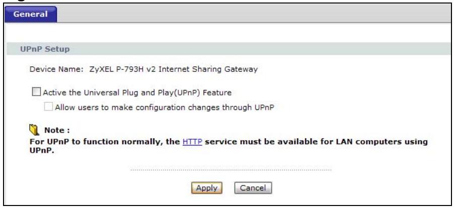
Figure 115 Advanced > UPnP > General
The following table describes the fields in this screen.
Table 77 Advanced > UPnP > General
| LABEL | DESCRIPTION |
| Active the Universal Plug and Play (UPnP) Feature | Select this check box to activate UPnP. Be aware that anyone could use a UPnP application to open the web configurator's login screen without entering the P-793H v2's IP address (although you must still enter the password to access the web configurator). |
| Allow users to make configuration changes through UPnP | Select this check box to allow UPnP-enabled applications to automatically configure the P-793H v2 so that they can communicate through the P-793H v2, for example by using NAT traversal, UPnP applications automatically reserve a NAT forwarding port in order to communicate with another UPnP enabled device; this eliminates the need to manually configure port forwarding for the UPnP enabled application. |
| Apply | Click this to save your changes. |
| Cancel | Click this to restore your previously saved settings. |
18.3 Installing UPnP in Windows Example
This section shows how to install UPnP in Windows Me and Windows XP.
Installing UPnP in Windows Me
Follow the steps below to install the UPnP in Windows Me.
1 Click Start and Control Panel. Double-click Add/Remove Programs.
2 Click on the Windows Setup tab and select Communication in the Components selection box. Click Details.
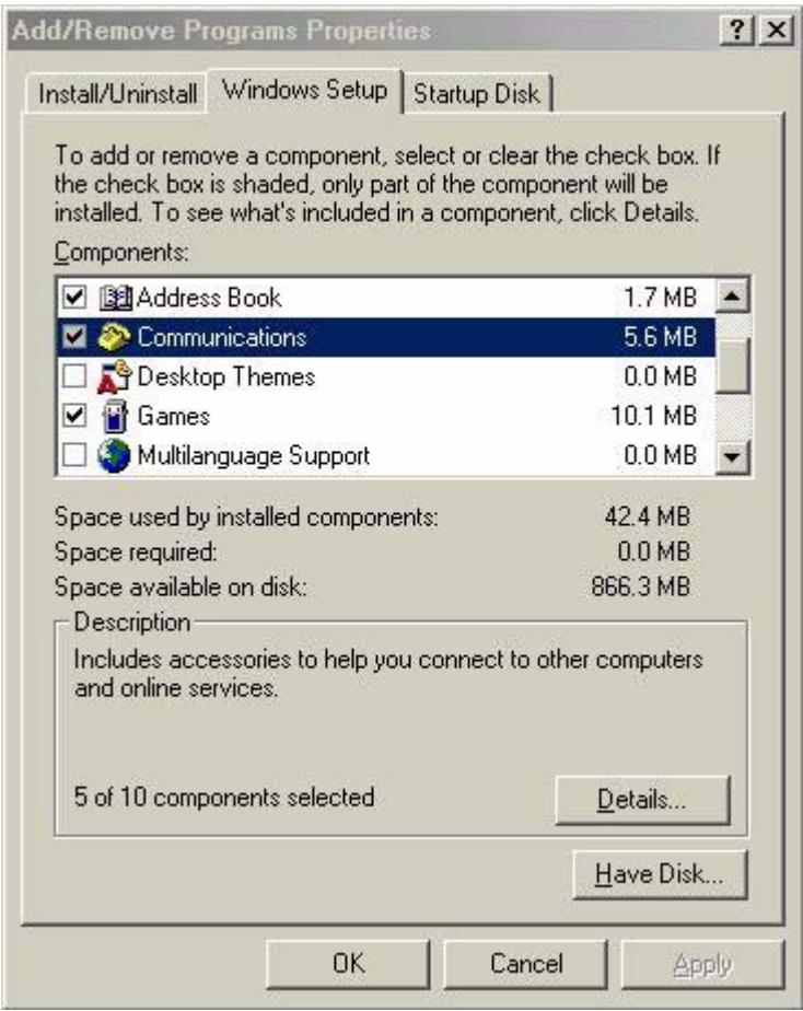
3 In the Communications window, select the Universal Plug and Play check box in the Components selection box.
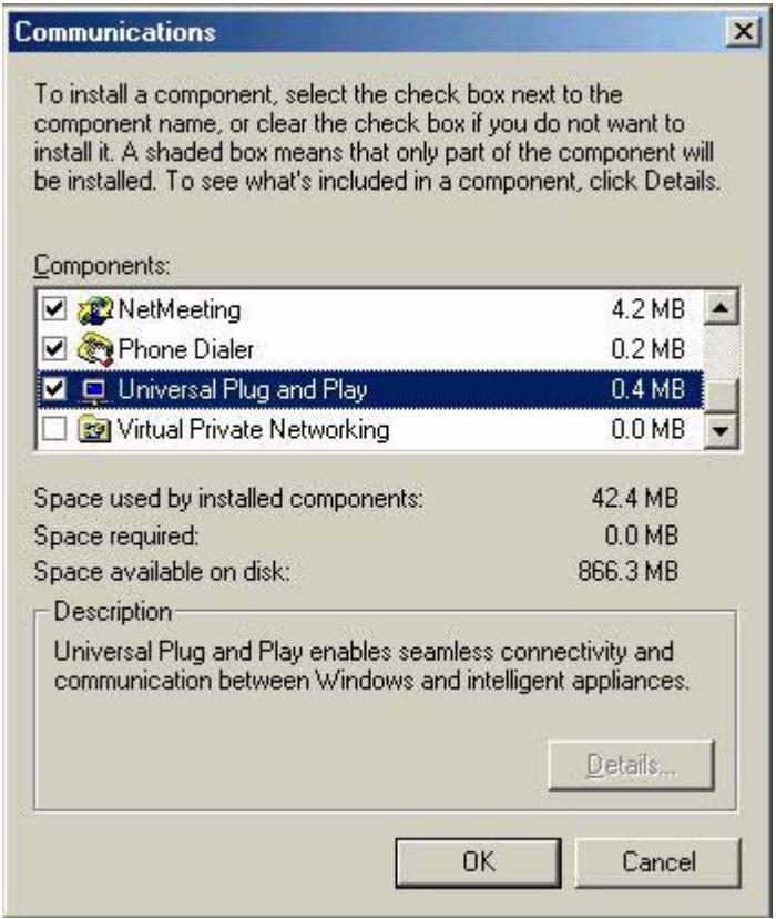
4 Click OK to go back to the Add/Remove Programs Properties window and click Next.
5 Restart the computer when prompted.
Installing UPnP in Windows XP
Follow the steps below to install the UPnP in Windows XP.
1 Click Start and Control Panel.
2 Double-click Network Connections.
3 In the Network Connections window, click Advanced in the main menu and select Optional Networking Components ....
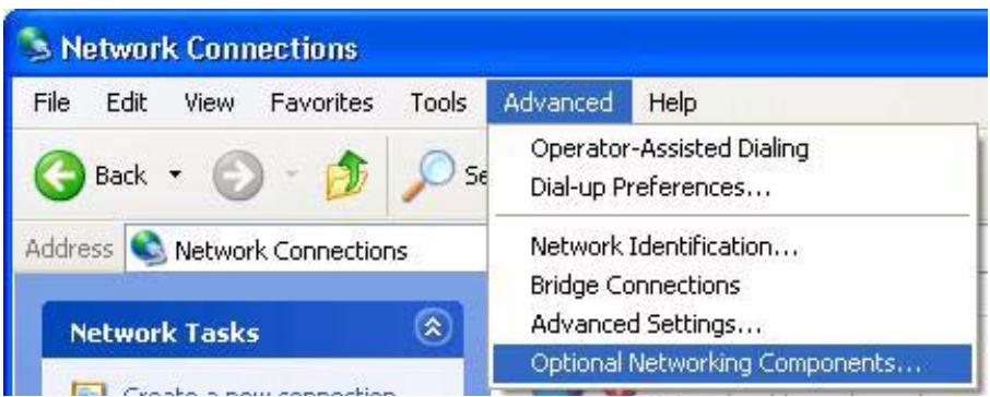
4 The Windows Optional Networking Components Wizard window displays. Select Networking Service in the Components selection box and click Details.
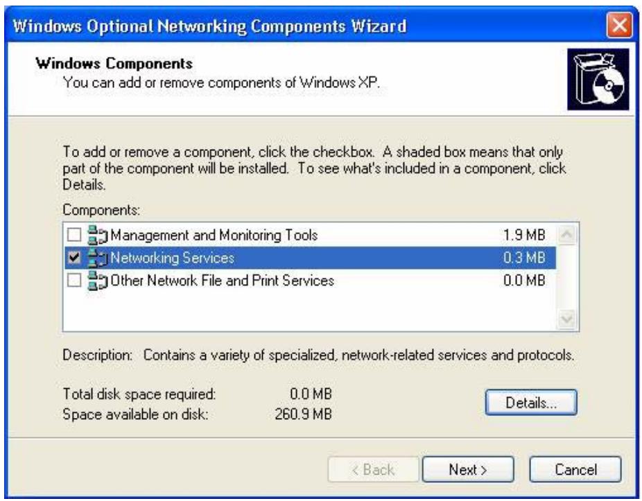
5 In the Networking Services window, select the Universal Plug and Play check box.
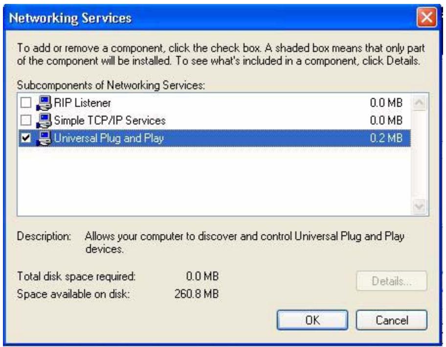
6 Click OK to go back to the Windows Optional Networking Component Wizard window and click Next.
18.4 Using UPnP in Windows XP Example
This section shows you how to use the UPnP feature in Windows XP. You must already have UPnP installed in Windows XP and UPnP activated on the P-793H v2.
Make sure the computer is connected to a LAN port of the P-793H v2. Turn on your computer and the P-793H v2.
Auto-discover Your UPnP-enabled Network Device
1 Click Start and Control Panel. Double-click Network Connections. An icon displays under Internet Gateway.
2 Right-click the icon and select Properties.
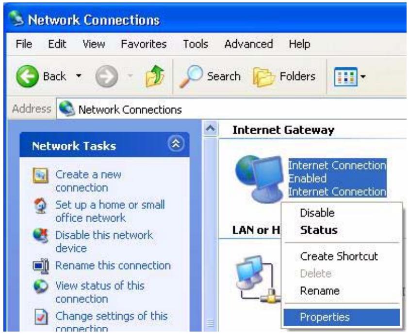
3 In the Internet Connection Properties window, click Settings to see the port mappings there were automatically created.
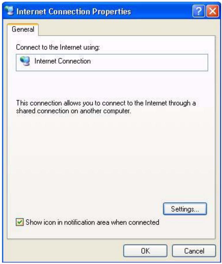
4 You may edit or delete the port mappings or click Add to manually add port mappings.
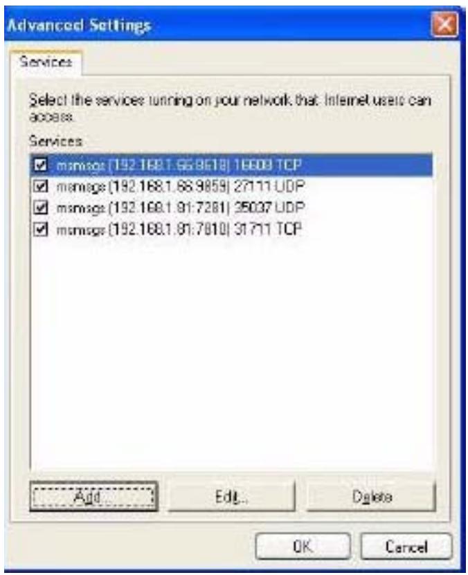
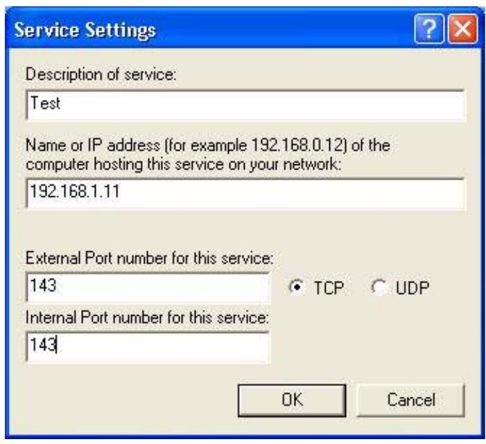
5 When the UPnP-enabled device is disconnected from your computer, all port mappings will be deleted automatically.
6 Select Show icon in notification area when connected option and click OK. An icon displays in the system tray.

7 Double-click on the icon to display your current Internet connection status.
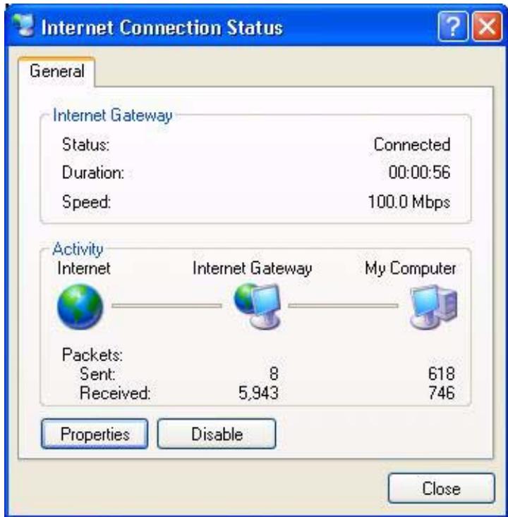
Web Configurator Easy Access
With UPnP, you can access the web-based configurator on the P-793H v2 without finding out the IP address of the P-793H v2 first. This comes helpful if you do not know the IP address of the P-793H v2.
Follow the steps below to access the web configurator.
1 Click Start and then Control Panel.
2 Double-click Network Connections.
3 Select My Network Places under Other Places.
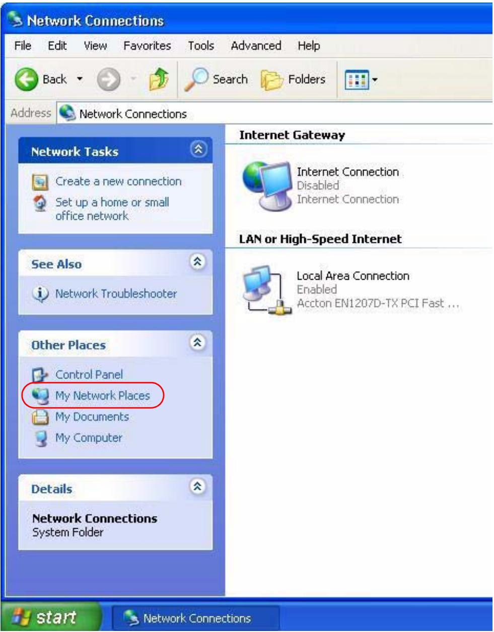
4 An icon with the description for each UPnP-enabled device displays under Local Network.
5 Right-click on the icon for your P-793H v2 and select Invoke. The web configurator login screen displays.
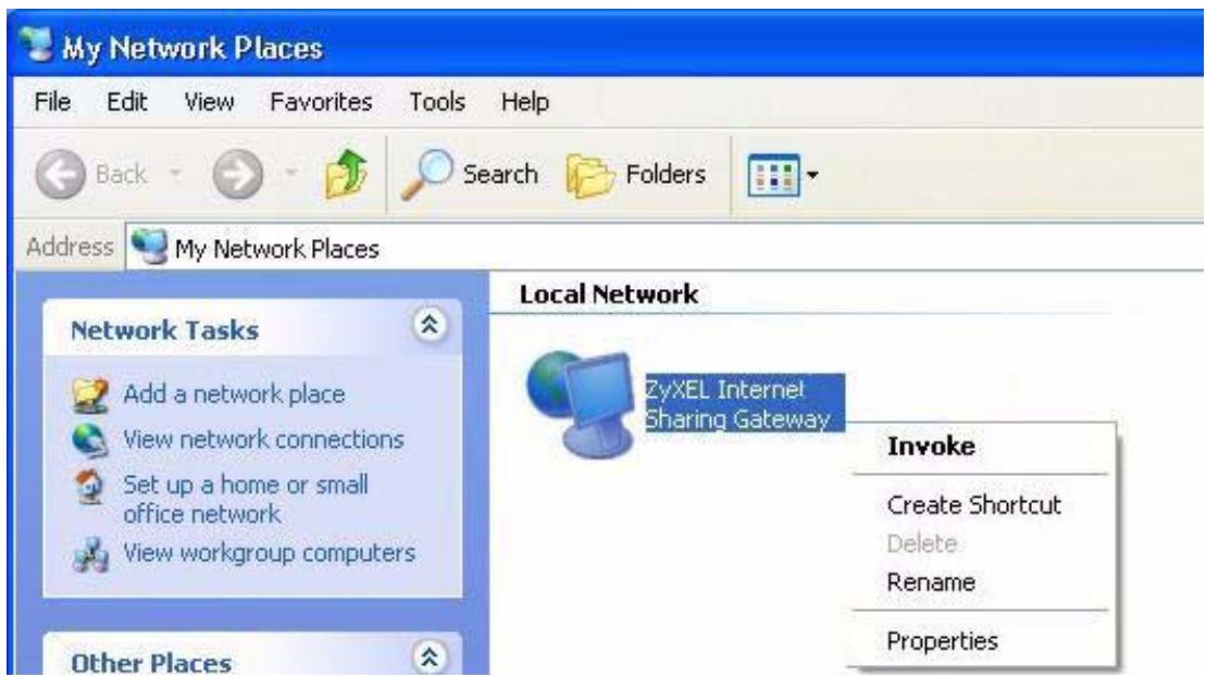
6 Right-click on the icon for your P-793H v2 and select Properties. A properties window displays with basic information about the P-793H v2.
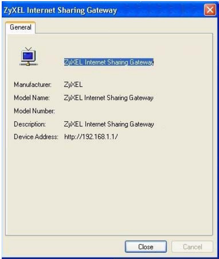
System Settings
19.1 Overview
This chapter shows you how to configure system related settings, such as system time, password, name, the domain name and the inactivity timeout interval.
19.1.1 What You Can Do in the System Settings Screens
- Use the General screen (Section 19.2 on page 264) to configure system settings.
- Use the Time Setting screen (Section 19.3 on page 266) to set the system time.
19.1.2 What You Need to Know About System Settings
DHCP
DHCP (Dynamic Host Configuration Protocol) is a method of allocating IP addresses to devices on a network from a DHCP Server. Often your ISP or a router on your network performs this function.
LAN
A LAN (local area network) is typically a network which covers a small area, made up of computers and other devices which share resources such as Internet access, printers etc.
19.2 The General Screen
Use this screen to configure system settings such as the system and domain name, inactivity timeout interval and system password.
The System Name is for identification purposes. However, because some ISPs check this name you should enter your computer's "Computer Name". Find the system name of your Windows computer by following one of the steps below.
- In Windows 95/98 click Start, Settings, Control Panel, Network. Click the Identification tab, note the entry for the Computer Name field and enter it as the System Name.
- In Windows 2000, click Start, Settings, Control Panel and then double-click System. Click the Network Identification tab and then the Properties button. Note the entry for the Computer name field and enter it as the System Name.
- In Windows XP, click start, My Computer, View system information and then click the Computer Name tab. Note the entry in the Full computer name field and enter it as the P-793H v2 System Name.
Click Maintenance > System to open the General screen.
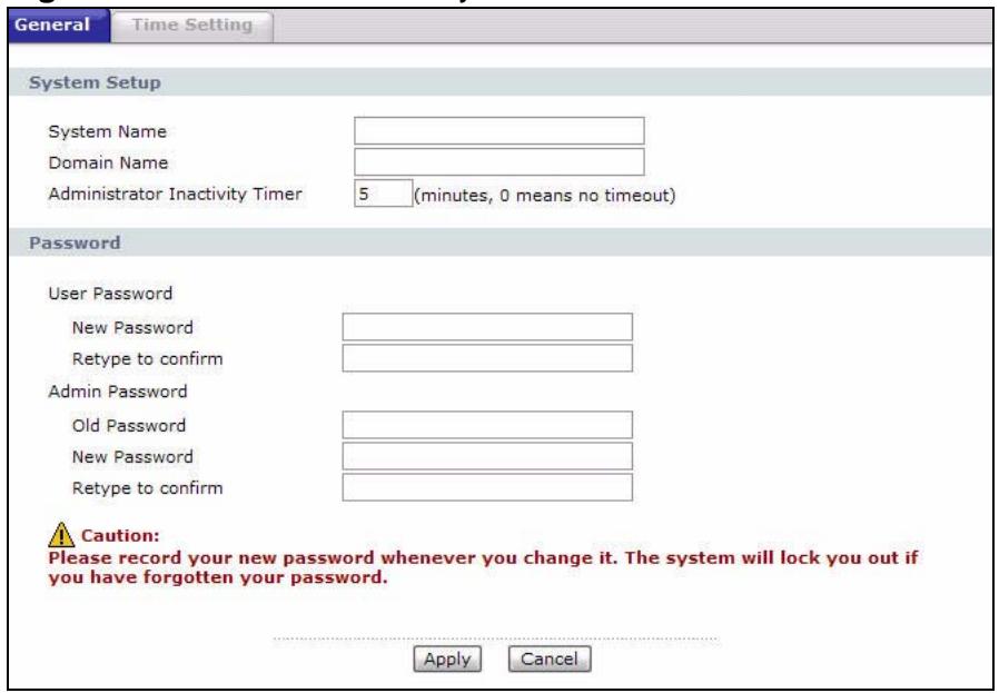
Figure 116 Maintenance > System > General
The following table describes the labels in this screen.
Table 78 Maintenance > System > General
| LABEL | DESCRIPTION |
| System Setup | |
| System Name | Choose a descriptive name for identification purposes. It is recommended you enter your computer's "Computer name" in this field. This name can be up to 30 alphanumeric characters long. Spaces are not allowed, but dashes "- " and underscores "_ " are accepted. |
| Domain Name | Enter the domain name (if you know it) here. If you leave this field blank, the ISP may assign a domain name via DHCP.The domain name entered by you is given priority over the ISP assigned domain name.The Domain Name entry is propagated to the DHCP clients on the LAN. |
| Administrator Inactivity Timer | Type how many minutes a management session (either via the web configurator or telnet) can be left idle before the session times out. The default is 5 minutes. After it times out you have to log in with your password again. Very long idle timeouts may have security risks. A value of "0" means a management session never times out, no matter how long it has been left idle (not recommended). |
| Password | |
| User Password | |
| New Password | Type your new user password (up to 30 characters). Note that as you type a password, the screen displays a (*) for each character you type. After you change the password, use the new password to access the P-793H v2. |
| Retype to confirm | Type the new password again for confirmation. |
| Admin Password | |
| Old Password | Type the default password or the existing password you use to access the system in this field. |
| New Password | Type your new system password (up to 30 characters). Note that as you type a password, the screen displays a (*) for each character you type. After you change the password, use the new password to access the P-793H v2. |
| Retype to confirm | Type the new password again for confirmation. |
| Apply | Click this to save your changes. |
| Cancel | Click this to restore your previously saved settings. |
19.3 The Time Setting Screen
Use this screen to configure the P-793H v2's time based on your local time zone. To change your P-793H v2's time and date, click Maintenance > System > Time Setting. The screen appears as shown.
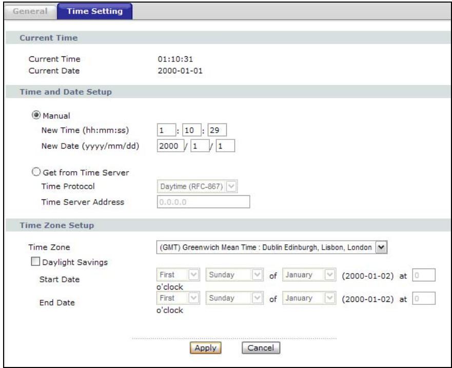
Figure 117 Maintenance > System > Time Setting
The following table describes the fields in this screen.
Table 79 Maintenance > System > Time Setting
| LABEL | DESCRIPTION |
| Current Time | |
| Current Time | This field displays the time of your P-793H v2. Each time you reload this page, the P-793H v2 synchronizes the time with the time server. |
| Current Date | This field displays the date of your P-793H v2. Each time you reload this page, the P-793H v2 synchronizes the date with the time server. |
| Time and Date Setup | |
| Manual | Select this radio button to enter the time and date manually. If you configure a new time and date, Time Zone and Daylight Saving at the same time, the new time and date you entered has priority and the Time Zone and Daylight Saving settings do not affect it. |
| New Time (hh:mm:ss) | This field displays the last updated time from the time server or the last time configured manually. When you set Time and Date Setup to Manual, enter the new time in this field and then click Apply. |
| New Date (yyyy/mm/dd) | This field displays the last updated date from the time server or the last date configured manually. When you set Time and Date Setup to Manual, enter the new date in this field and then click Apply. |
| Get from Time Server | Select this radio button to have the P-793H v2 get the time and date from the time server you specified below. |
| Time Protocol | Select the time service protocol that your time server sends when you turn on the P-793H v2. Not all time servers support all protocols, so you may have to check with your ISP/network administrator or use trial and error to find a protocol that works. The main difference between them is the format. Daytime (RFC 867) format is day/month/year/time zone of the server. Time (RFC 868) format displays a 4-byte integer giving the total number of seconds since 1970/1/1 at 0:0:0. The default, NTP (RFC 1305), is similar to Time (RFC 868). |
| Time Server Address | Enter the IP address or URL (up to 20 extended ASCII characters in length) of your time server. Check with your ISP/network administrator if you are unsure of this information. |
| Time Zone Setup | |
| Time Zone | Choose the time zone of your location. This will set the time difference between your time zone and Greenwich Mean Time (GMT). |
| Daylight Savings | Daylight saving is a period from late spring to early fall when many countries set their clocks ahead of normal local time by one hour to give more daytime light in the evening. Select this option if you use Daylight Saving Time. |
| Start Date | Configure the day and time when Daylight Saving Time starts if you selected Enable Daylight Saving. The o'clock field uses the 24 hour format. Here are a couple of examples: Daylight Saving Time starts in most parts of the United States on the second Sunday of March. Each time zone in the United States starts using Daylight Saving Time at 2 A.M. local time. So in the United States you would select Second, Sunday, March and type 2 in the o'clock field. Daylight Saving Time starts in the European Union on the last Sunday of March. All of the time zones in the European Union start using Daylight Saving Time at the same moment (1 A.M. GMT or UTC). So in the European Union you would select Last, Sunday, March. The time you type in the o'clock field depends on your time zone. In Germany for instance, you would type 2 because Germany's time zone is one hour ahead of GMT or UTC (GMT+1). |
| End Date | Configure the day and time when Daylight Saving Time ends if you selected Enable Daylight Saving. The o'clock field uses the 24 hour format. Here are a couple of examples:Daylight Saving Time ends in the United States on the first Sunday of November. Each time zone in the United States stops using Daylight Saving Time at 2 A.M. local time. So in the United States you would select First, Sunday, November and type 2 in the o'clock field.Daylight Saving Time ends in the European Union on the last Sunday of October. All of the time zones in the European Union stop using Daylight Saving Time at the same moment (1 A.M. GMT or UTC). So in the European Union you would select Last, Sunday, October. The time you type in the o'clock field depends on your time zone. In Germany for instance, you would type 2 because Germany's time zone is one hour ahead of GMT or UTC (GMT+1). |
| Apply | Click this to save your changes. |
| Cancel | Click this to restore your previously saved settings. |
20.1 Overview
This chapter contains information about configuring general log settings and viewing the P-793H v2's logs.
The web configurator allows you to choose which categories of events and/or alerts to have the P-793H v2 log and then display the logs or have the P-793H v2 send them to an administrator (as e-mail) or to a syslog server.
20.1.1 What You Can Do in the Log Screens
- Use the View Log screen (Section 20.2 on page 270) to see the logs for the categories that you selected in the Log Settings screen.
- Use The Log Settings screen (Section 20.3 on page 271) to configure the mail server, the syslog server, when to send logs and what logs to send.
20.1.2 What You Need To Know About Logs
Alerts
An alert is a message that is enabled as soon as the event occurs. They include system errors, attacks (access control) and attempted access to blocked web sites. Some categories such as System Errors consist of both logs and alerts. You may differentiate them by their color in the View Log screen. Alerts display in red and logs display in black.
Logs
A log is a message about an event that occurred on your P-793H v2. For example, when someone logs in to the P-793H v2, you can set a schedule for how often logs should be enabled, or sent to a syslog server.
20.2 The View Log Screen
Use the View Log screen to see the logs for the categories that you selected in the Log Settings screen (see Section 20.3 on page 271). Click Maintenance > Logs to open the View Log screen.
Entries in red indicate alerts. The log wraps around and deletes the old entries after it fills. Click a column heading to sort the entries by that column's criteria. Click the heading cell again to reverse the sort order. A triangle indicates ascending or descending sort order.
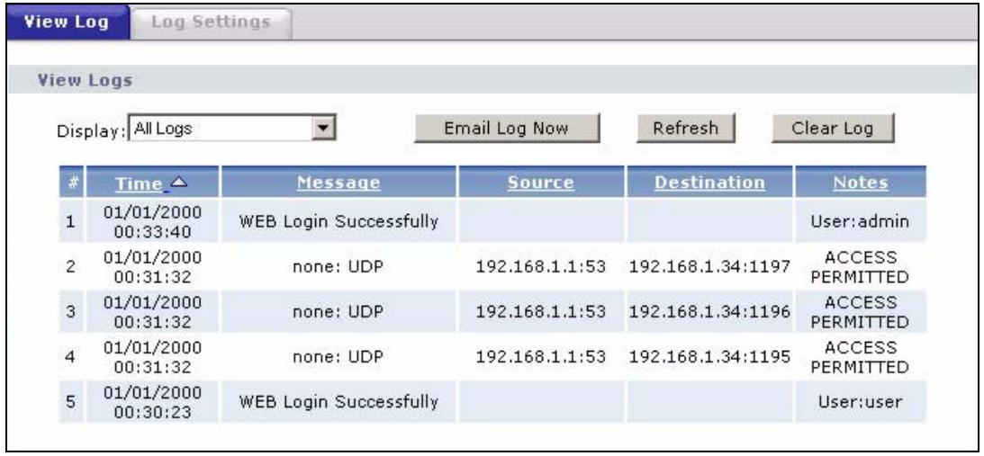
Figure 118 Maintenance > Logs > View Log
The following table describes the fields in this screen.
Table 80 Maintenance > Logs > View Log
| LABEL | DESCRIPTION |
| Display | The categories that you select in the Log Settings screen display in the drop-down list box. Select a category of logs to view; select All Logs to view logs from all of the log categories that you selected in the Log Settings page. |
| Email Log Now | Click this to send the log screen to the e-mail address specified in the Log Settings page (make sure that you have first filled in the E-mail Log Settings fields in Log Settings). |
| Refresh | Click this to renew the log screen. |
| Clear Log | Click this to delete all the logs. |
| # | This field is a sequential value and is not associated with a specific entry. |
| Time | This field displays the time the log was recorded. |
| Message | This field states the reason for the log. |
| Source | This field lists the source IP address and the port number of the incoming packet. |
Table 80 Maintenance > Logs > View Log
| LABEL | DESCRIPTION |
| Destination | This field lists the destination IP address and the port number of the incoming packet. |
| Notes | This field displays additional information about the log entry. |
20.3 The Log Settings Screen
Use the Log Settings screen to configure the mail server, the syslog server, when to send logs and what logs to send.
To change your P-793H v2's log settings, click Maintenance > Logs > Log Settings. The screen appears as shown.
Alerts are e-mailed as soon as they happen. Logs may be e-mailed as soon as the log is full. Selecting many alert and/or log categories (especially Access Control) may result in many e-mails being sent.
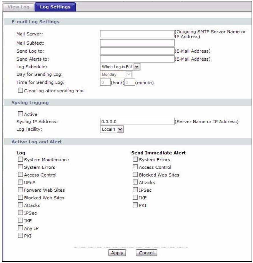
Figure 119 Maintenance > Logs > Log Settings
The following table describes the fields in this screen.
Table 81 Maintenance > Logs > Log Settings
| LABEL | DESCRIPTION |
| E-mail Log Settings | |
| Mail Server | Enter the server name or the IP address of the mail server for the e-mail addresses specified below. If this field is left blank, logs and alert messages will not be sent via E-mail. |
| Mail Subject | Type a title that you want to be in the subject line of the log e-mail message that the P-793H v2 sends. Not all P-793H v2 models have this field. |
| Send Log to | The P-793H v2 sends logs to the e-mail address specified in this field. If this field is left blank, the P-793H v2 does not send logs via e-mail. |
| Send Alerts to | Alerts are real-time notifications that are sent as soon as an event, such as a DoS attack, system error, or forbidden web access attempt occurs. Enter the E-mail address where the alert messages will be sent. Alerts include system errors, attacks and attempted access to blocked web sites. If this field is left blank, alert messages will not be sent via E-mail. |
| Log Schedule | This drop-down menu is used to configure the frequency of log messages being sent as E-mail: • Daily • Weekly • Hourly • When Log is Full • None. If you select Weekly or Daily, specify a time of day when the E-mail should be sent. If you select Weekly, then also specify which day of the week the E-mail should be sent. If you select When Log is Full, an alert is sent when the log fills up. If you select None, no log messages are sent. |
| Day for Sending Log | Use the drop down list box to select which day of the week to send the logs. |
| Time for Sending Log | Enter the time of the day in 24-hour format (for example 23:00 equals 11:00 pm) to send the logs. |
| Clear log after sending mail | Select the checkbox to delete all the logs after the P-793H v2 sends an E-mail of the logs. |
| Syslog Logging | The P-793H v2 sends a log to an external syslog server. |
| Active | Click Active to enable syslog logging. |
| Syslog IP Address | Enter the server name or IP address of the syslog server that will log the selected categories of logs. |
| Log Facility | Select a location from the drop down list box. The log facility allows you to log the messages to different files in the syslog server. Refer to the syslog server manual for more information. |
| Active Log and Alert | |
| Log | Select the categories of logs that you want to record. |
Table 81 Maintenance > Logs > Log Settings
| LABEL | DESCRIPTION |
| Send Immediate Alert | Select log categories for which you want the P-793H v2 to send E-mail alerts immediately. |
| Apply | Click this to save your customized settings and exit this screen. |
| Cancel | Click this to restore your previously saved settings. |
20.4 SMTP Error Messages
If there are difficulties in sending e-mail the following error message appears.
"SMTP action request failed. ret = ???". The "???are described in the following table.
Table 82 SMTP Error Messages
| -1 means P-793H v2 out of socket |
| -2 means tcp SYN fail |
| -3 means smtp server OK fail |
| -4 means HELO fail |
| -5 means MAIL FROM fail |
| -6 means RCPT TO fail |
| -7 means DATA fail |
| -8 means mail data send fail |
20.4.1 Example E-mail Log
An "End of Log" message displays for each mail in which a complete log has been sent. The following is an example of a log sent by e-mail.
-
You may edit the subject title.
-
"End of Log" message shows that a complete log has been sent.
Figure 120 E-mail Log Example
Subject: Firewall Alert From Date: Fri, 07 Apr 2000 10:05:42 From: user@zyxel.com To: user@zyxel.com 1|Apr 7 00 |From:192.168.1.1 To:192.168.1.255 default policy forward 09:54:03 UDP src port:00520 dest port:00520 <1,00> 2|Apr 7 00 |From:192.168.1.131 To:192.168.1.255 default policy forward 09:54:17 UDP src port:00520 dest port:00520 <1,00> 3|Apr 7 00 |From:192.168.1.6 To:10.10.10.10 match forward 09:54:19 UDP src port:03516 dest port:00053 <1,01>
{snip}
{snip}
126|Apr 7 00 |From:192.168.1.1 To:192.168.1.255 match forward 10:05:00 UDP src port:00520 dest port:00520 <1,02>
127|Apr 7 00 |From:192.168.1.131 To:192.168.1.255 match forward 10:05:17 UDP src port:00520 dest port:00520 <1,02>
128|Apr 7 00 |From:192.168.1.1 To:192.168.1.255 match forward 10:05:30 UDP src port:00520 dest port:00520 <1,02>
End of Firewall Log
20.5 Log Descriptions
This section provides descriptions of example log messages.
Table 83 System Maintenance Logs
| LOGMESSAGE | DESCRIPTION |
| Time calibration is successful | The router has adjusted its time based on information from the time server. |
| Time calibration failed | The router failed to get information from the time server. |
| WAN interface gets IP: %s | A WAN interface got a new IP address from the DHCP, PPPoE, or dial-up server. |
| DHCP client IP expired | A DHCP client's IP address has expired. |
| DHCP server assigns %s | The DHCP server assigned an IP address to a client. |
| Successful WEB login | Someone has logged on to the router's web configurator interface. |
| WEB login failed | Someone has failed to log on to the router's web configurator interface. |
| Successful TELNET login | Someone has logged on to the router via telnet. |
| TELNET login failed | Someone has failed to log on to the router via telnet. |
| Successful FTP login | Someone has logged on to the router via ftp. |
| FTP login failed | Someone has failed to log on to the router via ftp. |
| NAT Session Table is Full! | The maximum number of NAT session table entries has been exceeded and the table is full. |
| Starting Connectivity Monitor | Starting Connectivity Monitor. |
| Time initialized by Daytime Server | The router got the time and date from the Daytime server. |
| Time initialized by Time server | The router got the time and date from the time server. |
| Time initialized by NTP server | The router got the time and date from the NTP server. |
| Connect to Daytime server fail | The router was not able to connect to the Daytime server. |
| Connect to Time server fail | The router was not able to connect to the Time server. |
| Connect to NTP server fail | The router was not able to connect to the NTP server. |
| Too large ICMP packet has been dropped | The router dropped an ICMP packet that was too large. |
| Configuration Change: PC = 0x%x, Task ID = 0x%x | The router is saving configuration changes. |
| Successful SSH login | Someone has logged on to the router's SSH server. |
| SSH login failed | Someone has failed to log on to the router's SSH server. |
| Successful HTTPS login | Someone has logged on to the router's web configurator interface using HTTPS protocol. |
| HTTPS login failed | Someone has failed to log on to the router's web configurator interface using HTTPS protocol. |
Table 84 System Error Logs
| LOGMESSAGE | DESCRIPTION |
| %sexceeds the max. number of session per host! | This attempt to create a NAT session exceeds the maximum number of NAT session table entries allowed to be created per host. |
| setNetBIOSFilter:%X | The router failed to allocate memory for the NetBIOS filter settings. |
| readNetBIOSFilter:%X | The router failed to allocate memory for the NetBIOS filter settings. |
| WAN connection is down. | A WAN connection is down. You cannot access the network through this interface. |
Table 85 Access Control Logs
| LOGMESSAGE | DESCRIPTION |
| Firewall default policy: [TCP | UDP | IGMP | ESP | GRE | OSPF ] <Packet Direction> | Attempted TCP/UDP/IGMP/ESP/GRE/OSPF access matched the default policy and was blocked or forwarded according to the default policy's setting. |
| Firewall rule [NOT] match: [TCP | UDP | IGMP | ESP | GRE | OSPF ] <Packet Direction>, <rule:%d> | Attempted TCP/UDP/IGMP/ESP/GRE/OSPF access matched (or did not match) a configured firewall rule (denoted by its number) and was blocked or forwarded according to the rule. |
| Triangle route packet forwarded: [TCP | UDP | IGMP | ESP | GRE | OSPF ] | The firewall allowed a triangle route session to pass through. |
| Packet without a NAT table entry blocked: [TCP | UDP | IGMP | ESP | GRE | OSPF ] | The router blocked a packet that didn't have a corresponding NAT table entry. |
| Router sent blocked web site message: TCP | The router sent a message to notify a user that the router blocked access to a web site that the user requested. |
Table 86 TCP Reset Logs
| LOGMESSAGE | DESCRIPTION |
| Under SYN flood attack, sent TCP RST | The router sent a TCP reset packet when a host was under a SYN flood attack (the TCP incomplete count is per destination host.) |
| Exceed TCP MAX incomplete, sent TCP RST | The router sent a TCP reset packet when the number of TCP incomplete connections exceeded the user configured threshold. (the TCP incomplete count is per destination host.) Note: Refer to TCP Maximum Incomplete in the Firewall Attack Alerts screen. |
| Peer TCP state out of order, sent TCP RST | The router sent a TCP reset packet when a TCP connection state was out of order. Note: The firewall refers to RFC793 Figure 6 to check the TCP state. |
| Firewall session time out, sent TCP RST | The router sent a TCP reset packet when a dynamic firewall session timed out.Default timeout values: ICMP idle timeout (s): 60UDP idle timeout (s): 60TCP connection (three way handshaking) timeout (s): 30TCP FIN-wait timeout (s): 60TCP idle (established) timeout (s): 3600 |
| Exceed MAX incomplete, sent TCP RST | The router sent a TCP reset packet when the number of incomplete connections (TCP and UDP) exceeded the user-configured threshold. (Incomplete count is for all TCP and UDP connections through the firewall.)Note: When the number of incomplete connections (TCP + UDP) > "Maximum Incomplete High", the router sends TCP RST packets for TCP connections and destroys TOS (firewall dynamic sessions) until incomplete connections < "Maximum Incomplete Low". |
| Access block, sent TCP RST | The router sends a TCP RST packet and generates this log if you turn on the firewall TCP reset mechanism (via CI command: "sys firewall tcprst"). |
Table 87 Packet Filter Logs
| LOGMESSAGE | DESCRIPTION |
| [TCP | UDP | ICMP | IGMP | Generic ] packet filter matched (set:%d, rule:%d) | Attempted access matched a configured filter rule (denoted by its set and rule number) and was blocked or forwarded according to the rule. |
For type and code details, see Table 96 on page 280.
Table 88 ICMP Logs
| LOGMESSAGE | DESCRIPTION |
| Firewall default policy: ICMP <Packet Direction>, <type:%d>, <code:%d> | ICMP access matched the default policy and was blocked or forwarded according to the user's setting. |
| Firewall rule [NOT] match: ICMP <Packet Direction>, <rule:%d>, <type:%d>, <code:%d> | ICMP access matched (or didn't match) a firewall rule (denoted by its number) and was blocked or forwarded according to the rule. |
| Triangle route packet forwarded: ICMP | The firewall allowed a triangle route session to pass through. |
| Packet without a NAT table entry blocked: ICMP | The router blocked a packet that didn't have a corresponding NAT table entry. |
| Unsupported/out-of-order ICMP: ICMP | The firewall does not support this kind of ICMP packets or the ICMP packets are out of order. |
| Router reply ICMP packet: ICMP | The router sent an ICMP reply packet to the sender. |
Table 89 CDR Logs
| LOGMESSAGE | DESCRIPTION |
| board %d line %d channel %d, call %d, %s C01 Outgoing Call dev=%x ch=%x %s | The router received the setup requirements for a call. "call" is the reference (count) number of the call. "dev" is the device type (3 is for dial-up, 6 is for PPPoE, 10 is for PPTP). "channel" or "ch" is the call channel ID. For example, "board 0 line 0 channel 0, call 3, C01 Outgoing Call dev=6 ch=0 "Means the router has dialed to the PPPoE server 3 times. |
| board %d line %d channel %d, call %d, %s C02 OutCall Connected %d %s | The PPPoE, PPTP or dial-up call is connected. |
| board %d line %d channel %d, call %d, %s C02 Call Terminated | The PPPoE, PPTP or dial-up call was disconnected. |
Table 90 PPP Logs
| LOGMESSAGE | DESCRIPTION |
| ppp:LCP Starting | The PPP connection's Link Control Protocol stage has started. |
| ppp:LCP Opening | The PPP connection's Link Control Protocol stage is opening. |
| ppp:CHAP Opening | The PPP connection's Challenge Handshake Authentication Protocol stage is opening. |
| ppp:IPCP Starting | The PPP connection's Internet Protocol Control Protocol stage is starting. |
| ppp:IPCP Opening | The PPP connection's Internet Protocol Control Protocol stage is opening. |
| ppp:LCP Closing | The PPP connection's Link Control Protocol stage is closing. |
| ppp:IPCP Closing | The PPP connection's Internet Protocol Control Protocol stage is closing. |
Table 91 UPnP Logs
| LOGMESSAGE | DESCRIPTION |
| UPnP pass through Firewall | UPnP packets can pass through the firewall. |
Table 92 Content Filtering Logs
| LOGMESSAGE | DESCRIPTION |
| %s: block keyword | The content of a requested web page matched a user defined keyword. |
| %s | The system forwarded web content. |
For type and code details, see Table 96 on page 280.
Table 93 Attack Logs
| LOGMESSAGE | DESCRIPTION |
| attack [ TCP | UDP | IGMP | ESP | GRE | OSPF ] | The firewall detected a TCP/UDP/IGMP/ESP/GRE/OSPF attack. |
| attack ICMP (type:%d, code:%d) | The firewall detected an ICMP attack. |
| land [ TCP | UDP | IGMP | ESP | GRE | OSPF ] | The firewall detected a TCP/UDP/IGMP/ESP/GRE/OSPF land attack. |
| land ICMP (type:%d, code:%d) | The firewall detected an ICMP land attack. |
| ip spoofing - WAN [ TCP | UDP | IGMP | ESP | GRE | OSPF ] | The firewall detected an IP spoofing attack on the WAN port. |
| ip spoofing - WAN ICMP (type:%d, code:%d) | The firewall detected an ICMP IP spoofing attack on the WAN port. |
| icmp echo : ICMP (type:%d, code:%d) | The firewall detected an ICMP echo attack. |
| syn flood TCP | The firewall detected a TCP syn flood attack. |
| ports scan TCP | The firewall detected a TCP port scan attack. |
| teardrop TCP | The firewall detected a TCP teardrop attack. |
| teardrop UDP | The firewall detected an UDP teardrop attack. |
| teardrop ICMP (type:%d, code:%d) | The firewall detected an ICMP teardrop attack. |
| illegal command TCP | The firewall detected a TCP illegal command attack. |
| NetBIOS TCP | The firewall detected a TCP NetBIOS attack. |
| ip spoofing - no routing entry [ TCP | UDP | IGMP | ESP | GRE | OSPF ] | The firewall classified a packet with no source routing entry as an IP spoofing attack. |
| ip spoofing - no routing entry ICMP (type:%d, code:%d) | The firewall classified an ICMP packet with no source routing entry as an IP spoofing attack. |
| vulnerability ICMP (type:%d, code:%d) | The firewall detected an ICMP vulnerability attack. |
| traceroute ICMP (type:%d, code:%d) | The firewall detected an ICMP traceroute attack. |
Table 94 802.1X Logs
| LOGMESSAGE | DESCRIPTION |
| RADIUS accepts user. | A user was authenticated by the RADIUS Server. |
| RADIUS rejects user. Pls check RADIUS Server. | A user was not authenticated by the RADIUS Server. Please check the RADIUS Server. |
| User logout because of session timeout expired. | The router logged out a user whose session expired. |
| User logout because of user deassociation. | The router logged out a user who ended the session. |
| User logout because of no authentication response from user. | The router logged out a user from which there was no authentication response. |
| User logout because of idle timeout expired. | The router logged out a user whose idle timeout period expired. |
| User logout because of user request. | A user logged out. |
| No response from RADIUS.Pls check RADIUS Server. | There is no response message from the RADIUS server, please check the RADIUS server. |
| Use RADIUS to authenticate user. | The RADIUS server is operating as the authentication server. |
| No Server to authenticate user. | There is no authentication server to authenticate a user. |
Table 95 ACL Setting Notes
| PACKET DIRECTION | DIRECTION | DESCRIPTION |
| (L to W) | LAN to WAN | ACL set for packets traveling from the LAN to the WAN. |
| (W to L) | WAN to LAN | ACL set for packets traveling from the WAN to the LAN. |
| (L to L/P-793H v2) | LAN to LAN/P-793H v2 | ACL set for packets traveling from the LAN to the LAN or the P-793H v2. |
| (W to W/P-793H v2) | WAN to WAN/P-793H v2 | ACL set for packets traveling from the WAN to the WAN or the P-793H v2. |
Table 96 ICMP Notes
| TYPE | CODE | DESCRIPTION |
| 0 | Echo Reply | |
| 0 | Echo reply message | |
| 3 | Destination Unreachable | |
| 0 | Net unreachable | |
| 1 | Host unreachable | |
| 2 | Protocol unreachable | |
| 3 | Port unreachable | |
| 4 | A packet that needed fragmentation was dropped because it was set to Don't Fragment (DF) | |
| 5 | Source route failed | |
| 4 | Source Quench | |
| 0 | A gateway may discard internet datagrams if it does not have the buffer space needed to queue the datagrams for output to the next network on the route to the destination network. | |
| 5 | Redirect | |
| 0 | Redirect datagrams for the Network | |
| 1 | Redirect datagrams for the Host | |
| 2 | Redirect datagrams for the Type of Service and Network | |
| 3 | Redirect datagrams for the Type of Service and Host | |
| 8 | Echo | |
| 0 | Echo message | |
| 11 | Time Exceeded | |
| 0 | Time to live exceeded in transit | |
| 1 | Fragment reassembly time exceeded | |
| 12 | Parameter Problem | |
| 0 | Pointer indicates the error | |
| 13 | Timestamp | |
| 0 | Timestamp request message | |
| 14 | Timestamp Reply | |
| 0 | Timestamp reply message | |
| 15 | Information Request | |
| 0 | Information request message | |
| 16 | Information Reply | |
| 0 | Information reply message |
Table 97 Syslog Logs
| LOGMESSAGE | DESCRIPTION |
| <Facility*8 + Severity>Mon dd hr:mm:ss hostname src="<srcIP:srcPort>" dst="<dstIP:dstPort>" msg="<msg>" note="<note>" devID="<mac address last three numbers>" cat="<category" | "This message is sent by the system ("RAS" displays as the system name if you haven't configured one) when the router generates a syslog. The facility is defined in the web MAIN MENU->LOGS->Log Settings page. The severity is the log's syslog class. The definition of messages and notes are defined in the various log charts throughout this appendix. The "devID" is the last three characters of the MAC address of the router's LAN port. The "cat" is the same as the category in the router's logs. |
The following table shows RFC-2408 ISAKMP payload types that the log displays. Please refer to RFC 2408 for detailed information on each type.
Table 98 RFC-2408 ISAKMP Payload Types
| LOG DISPLAY | PAYLOAD TYPE |
| SA | Security Association |
| PROP | Proposal |
| TRANS | Transform |
| KE | Key Exchange |
| ID | Identification |
| CER | Certificate |
| CER_REQ | Certificate Request |
| HASH | Hash |
| SIG | Signature |
| NONCE | Nonce |
| NOTFY | Notification |
| DEL | Delete |
| VID | Vendor ID |
21.1 Overview
This chapter explains how to upload new firmware, manage configuration files and restart your P-793H v2.
Use the instructions in this chapter to change the device's configuration file or upgrade its firmware. After you configure your device, you can backup the configuration file to a computer. That way if you later misconfigure the device, you can upload the backed up configuration file to return to your previous settings. You can alternately upload the factory default configuration file if you want to return the device to the original default settings. The firmware determines the device's available features and functionality. You can download new firmware releases from your nearest ZyXEL FTP site (or www.zyxel.com) to use to upgrade your device's performance.
Only use firmware for your device's specific model. Refer to the label on the bottom of your P-793H v2.
21.1.1 What You Can Do in the Tool Screens
- Use the Firmware Upgrade screen (Section 21.2 on page 291) to upload firmware to your device.
- Use the Configuration screen (Section 21.3 on page 293) to backup and restore device configurations. You can also reset your device settings back to the factory default.
- Use the Restart screen (Section 21.4 on page 295) to restart your ZyXEL device.
21.1.2 What You Need To Know About Tools
Filename Conventions
The configuration file (often called the romfile or rom-0) contains the factory default settings in the menus such as password, DHCP Setup, TCP/IP Setup, etc. It arrives from ZyXEL with a "rom" filename extension. Once you have customized the P-793H v2's settings, they can be saved back to your computer under a filename of your choosing.
ZyNOS (ZyXEL Network Operating System sometimes referred to as the "ras" file) is the system firmware and has a "bin" filename extension. Find this firmware at www.zyxel.com.With many FTP and TFTP clients, the filenames are similar to those seen next.
ftp> put firmware.bin ras
This is a sample FTP session showing the transfer of the computer file "firmware.bin" to the P-793H v2.
ftp> get rom-0 config.cfg
This is a sample FTP session saving the current configuration to the computer file "config.cfg".
If your (T)FTP client does not allow you to have a destination filename different than the source, you will need to rename them as the P-793H v2 only recognizes "rom-0" and "ras". Be sure you keep unaltered copies of both files for later use.
The following table is a summary. Please note that the internal filename refers to the filename on the P-793H v2 and the external filename refers to the filename not on the P-793H v2, that is, on your computer, local network or FTP site and so the name (but not the extension) may vary. After uploading new firmware, see the Status screen to confirm that you have uploaded the correct firmware version.
Table 99 Filename Conventions
| FILE TYPE | INTERNAL NAME | EXTERNAL NAME | DESCRIPTIO N |
| Configuration File | Rom-0 | This is the configuration filename on the P-793H v2. Uploading the rom-0 file replaces the entire ROM file system, including your P-793H v2 configurations, system-related data (including the default password), the error log and the trace log. | *.rom |
| Firmware | Ras | This is the generic name for the ZyNOS firmware on the P-793H v2. | *.bin |
FTP Restrictions
FTP will not work when:
1 The firewall is active (turn the firewall off or create a firewall rule to allow access from the WAN).
2 You have disabled the FTP service in the Remote Management screen.
3 The IP you entered in the Secured Client IP field does not match the client IP. If it does not match, the device will disallow the FTP session.
21.1.3 Before You Begin
- Ensure you have either created a firewall rule to allow access from the WAN or turned the firewall off, otherwise the FTP will not function.
- Make sure the FTP service has not been disabled in the Remote Management screen.
21.1.4 Tool Examples
Using FTP or TFTP to Restore Configuration
This example shows you how to restore a previously saved configuration. Note that this function erases the current configuration before restoring a previous backup configuration; please do not attempt to restore unless you have a backup configuration file stored on disk.
FTP is the preferred method for restoring your current computer configuration to your device since FTP is faster. Please note that you must wait for the system to automatically restart after the file transfer is complete.
Do not interrupt the file transfer process as this may PERMANENTLY DAMAGE your device. When the Restore Configuration process is complete, the device automatically restarts.
Restore Using FTP Session Example
Figure 121 Restore Using FTP Session Example
ftp> put config.rom rom-0
200 Port command okay
150 Opening data connection for STOR rom-0
226 File received OK
221 Goodbye for writing flash
ftp: 16384 bytes sent in 0.06Seconds 273.07Kbytes/sec.
ftp>quit
Refer to Section 21.1.2 on page 284 to read about configurations that disallow FTP and FTP over WAN.
FTP and TFTP Firmware and Configuration File Uploads
These examples show you how to upload firmware and configuration files.
Do not interrupt the file transfer process as this may PERMANENTLY DAMAGE your device.
FTP is the preferred method for uploading the firmware and configuration. To use this feature, your computer must have an FTP client. The following sections give examples of how to upload the firmware and the configuration files.
FTP File Upload Command from the DOS Prompt Example
1 Launch the FTP client on your computer.
2 Enter "open", followed by a space and the IP address of your device.
3 Press [ENTER] when prompted for a username.
4 Enter your password as requested (the default is "1234").
5 Enter "bin" to set transfer mode to binary.
6 Use "put" to transfer files from the computer to the device, for example, "put firmware.bin ras" transfers the firmware on your computer (firmware.bin) to the device and renames it "ras". Similarly, "put config.rom rom-0" transfers the configuration file on your computer (config.rom) to the device and renames it "rom-0". Likewise "get rom-0 config.rom" transfers the configuration file on the device to your computer and renames it "config.rom." See earlier in this chapter for more information on filename conventions.
7 Enter "quit" to exit the ftp prompt.
FTP Session Example of Firmware File Upload
Figure 122 FTP Session Example of Firmware File Upload
331 Enter PASS command
Password:
230 Logged in
ftp> bin
200 Type I OK
ftp> put firmware.bin ras
200 Port command okay
150 Opening data connection for STOR ras
226 File received OK
ftp: 1103936 bytes sent in 1.10Seconds 297.89Kbytes/sec.
ftp> quit
More commands (found in GUI-based FTP clients) are listed in this chapter.
Refer to Section 21.1.2 on page 284 to read about configurations that disallow TFTP and FTP over WAN.
TFTP File Upload
The device also supports the uploading of firmware files using TFTP (Trivial File Transfer Protocol) over LAN. Although TFTP should work over WAN as well, it is not recommended.
To use TFTP, your computer must have both telnet and TFTP clients. To transfer the firmware and the configuration file, follow the procedure shown next.
1 Use telnet from your computer to connect to the device and log in. Because TFTP does not have any security checks, the device records the IP address of the telnet client and accepts TFTP requests only from this address.
2 Enter the command "sys stdio 0" to disable the management idle timeout, so the TFTP transfer will not be interrupted. Enter "command sys stdio 5" to restore the five-minute management idle timeout (default) when the file transfer is complete.
3 Launch the TFTP client on your computer and connect to the device. Set the transfer mode to binary before starting data transfer.
4 Use the TFTP client (see the example below) to transfer files between the device and the computer. The file name for the firmware is "ras".
Note that the telnet connection must be active and the device in CI mode before and during the TFTP transfer. For details on TFTP commands (see following example), please consult the documentation of your TFTP client program. For
UNIX, use "get" to transfer from the device to the computer, "put" the other way around, and "binary" to set binary transfer mode.
TFTP Upload Command Example
The following is an example TFTP command:
tftp [-i] host put firmware.bin ras
Where "i" specifies binary image transfer mode (use this mode when transferring binary files), "host" is the device's IP address, "put" transfers the file source on the computer (firmware.bin - name of the firmware on the computer) to the file destination on the remote host (ras - name of the firmware on the device).
Commands that you may see in GUI-based TFTP clients are listed earlier in this chapter.
Using the FTP Commands to Back Up Configuration
1 Launch the FTP client on your computer.
2 Enter "open", followed by a space and the IP address of your P-793H v2.
3 Press [ENTER] when prompted for a username.
4 Enter your password as requested (the default is "1234").
5 Enter "bin" to set transfer mode to binary.
6 Use "get" to transfer files from the P-793H v2 to the computer, for example, "get rom-0 config.rom" transfers the configuration file on the P-793H v2 to your computer and renames it "config.rom". See earlier in this chapter for more information on filename conventions.
7 Enter "quit" to exit the ftp prompt.
FTP Command Configuration Backup Example
This figure gives an example of using FTP commands from the DOS command prompt to save your device's configuration onto your computer.
Figure 123 FTP Session Example
331 Enter PASS command
Password:
230 Logged in
ftp> bin
200 Type I OK
ftp> get rom-0 zyxel.rom
200 Port command okay
150 Opening data connection for STOR ras
226 File received OK
ftp: 16384 bytes sent in 1.10Seconds 297.89Kbytes/sec.
ftp> quit
Configuration Backup Using GUI-based FTP Clients
The following table describes some of the commands that you may see in GUI-based FTP clients.
Table 100 General Commands for GUI-based FTP Clients
| COMMAND | DESCRIPTION |
| Host Address | Enter the address of the host server. |
| Login Type | Anonymous.This is when a user I.D. and password is automatically supplied to the server for anonymous access. Anonymous logins will work only if your ISP or service administrator has enabled this option.Normal.The server requires a unique User ID and Password to login. |
| Transfer Type | Transfer files in either ASCII (plain text format) or in binary mode. |
| Initial Remote Directory | Specify the default remote directory (path). |
| Initial Local Directory | Specify the default local directory (path). |
Backup Configuration Using TFTP
The P-793H v2 supports the up/downloading of the firmware and the configuration file using TFTP (Trivial File Transfer Protocol) over LAN. Although TFTP should work over WAN as well, it is not recommended.
To use TFTP, your computer must have both telnet and TFTP clients. To backup the configuration file, follow the procedure shown next.
1 Use telnet from your computer to connect to the P-793H v2 and log in. Because TFTP does not have any security checks, the P-793H v2 records the IP address of the telnet client and accepts TFTP requests only from this address.
2 Enter command "sys stdio 0" to disable the management idle timeout, so the TFTP transfer will not be interrupted. Enter command "sys stdio 5" to restore the five-minute management idle timeout (default) when the file transfer is complete.
3 Launch the TFTP client on your computer and connect to the P-793H v2. Set the transfer mode to binary before starting data transfer.
4 Use the TFTP client (see the example below) to transfer files between the P-793H v2 and the computer. The file name for the configuration file is "rom-0" (rom-zero, not capital o).
Note that the telnet connection must be active before and during the TFTP transfer. For details on TFTP commands (see following example), please consult the documentation of your TFTP client program. For UNIX, use "get" to transfer from the P-793H v2 to the computer and "binary" to set binary transfer mode.
TFTP Command Configuration Backup Example
The following is an example TFTP command:
ftftp [-i] host get rom-0 config.rom
where "i" specifies binary image transfer mode (use this mode when transferring binary files), "host" is the P-793H v2 IP address, "get" transfers the file source on the P-793H v2 (rom-0, name of the configuration file on the P-793H v2) to the file destination on the computer and renames it config.rom.
Configuration Backup Using GUI-based TFTP Clients
The following table describes some of the fields that you may see in GUI-based TFTP clients.
Table 101 General Commands for GUI-based TFTP Clients
| COMMAND | DESCRIPTION |
| Host | Enter the IP address of the P-793H v2. 192.168.1.1 is the P-793H v2's default IP address when shipped. |
| Send/ Fetch | Use “Send” to upload the file to the P-793H v2 and “Fetch” to back up the file on your computer. |
| Local File | Enter the path and name of the firmware file (*.bin extension) or configuration file (*.rom extension) on your computer. |
| Remote File | This is the filename on the P-793H v2. The filename for the firmware is “ras” and for the configuration file, is “rom-0”. |
| Binary | Transfer the file in binary mode. |
| Abort | Stop transfer of the file. |
Refer to Section 21.1.2 on page 284 to read about configurations that disallow FTP and FTP over WAN.
21.2 The Firmware Screen
Click Maintenance > Tools to open the Firmware screen. Follow the instructions in this screen to upload firmware to your P-793H v2. The upload process uses HTTP (Hypertext Transfer Protocol) and may take up to two minutes. After a successful upload, the system will reboot. See Section 21.1.4 on page 285 for upgrading firmware using FTP/TFTP commands.
Do NOT turn off the P-793H v2 while firmware upload is in progress!
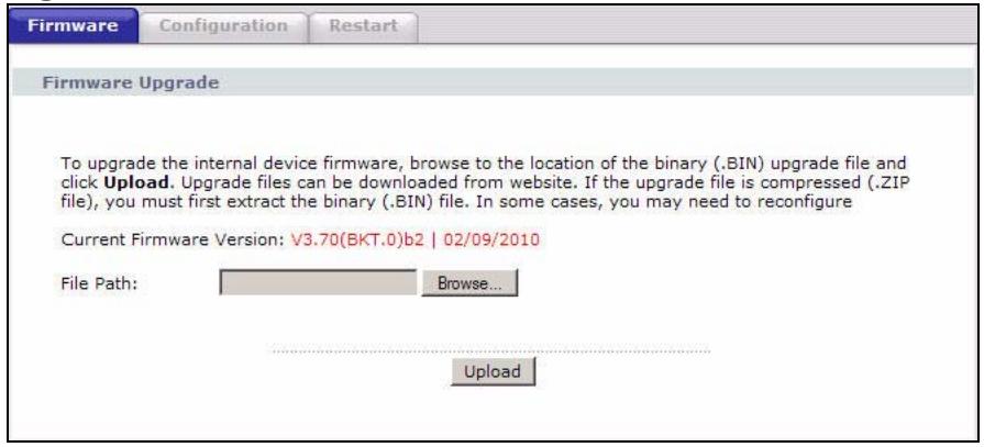
Figure 124 Maintenance > Tools > Firmware
The following table describes the labels in this screen.
Table 102 Maintenance > Tools > Firmware
| LABEL | DESCRIPTION |
| Current Firmware Version | This is the present Firmware version and the date created. |
| File Path | Type in the location of the file you want to upload in this field or click Browse … to find it. |
| Browse... | Click this to find the .bin file you want to upload. Remember that you must decompress compressed (.zip) files before you can upload them. |
| Upload | Click this to begin the upload process. This process may take up to two minutes. |
After you see the Firmware Upload in Progress screen, wait two minutes before logging into the P-793H v2 again.
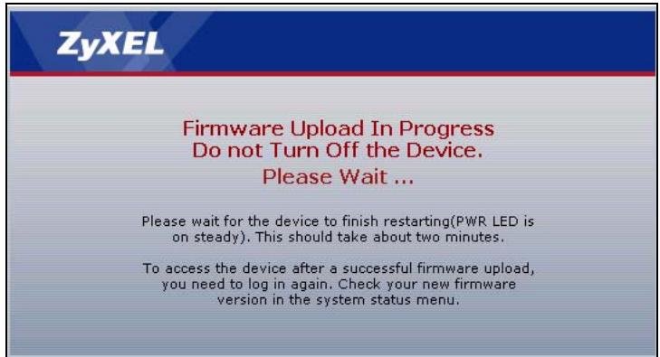
Figure 125 Firmware Upload In Progress
The P-793H v2 automatically restarts in this time causing a temporary network disconnect. In some operating systems, you may see the following icon on your desktop.
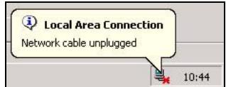
Figure 126 Network Temporarily Disconnected
After two minutes, log in again and check your new firmware version in the Status screen.
If the upload was not successful, the following screen will appear. Click Return to go back to the Firmware screen.
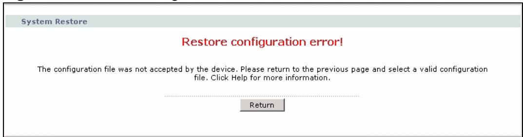
Figure 127 Error Message
21.3 The Configuration Screen
See Section 21.1.4 on page 285 for transferring configuration files using FTP/TFTP commands.
Click Maintenance > Tools > Configuration. Information related to factory defaults, backup configuration, and restoring configuration appears in this screen, as shown next.
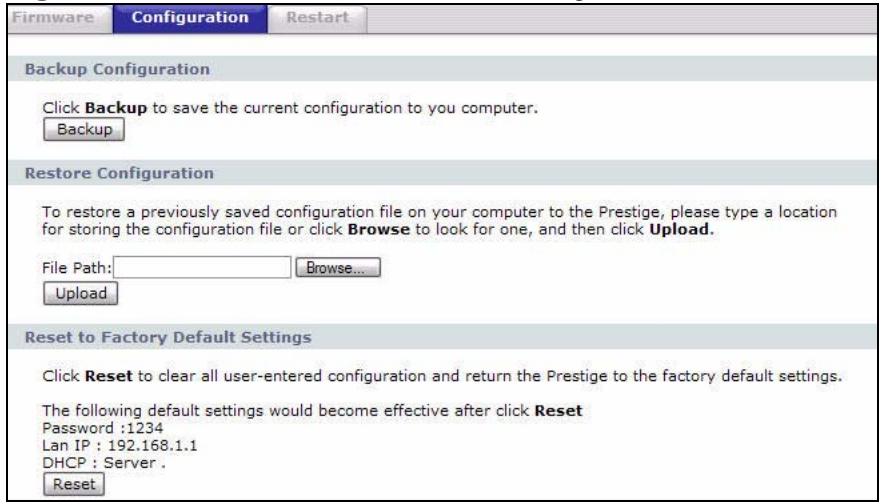
Figure 128 Maintenance > Tools > Configuration
Backup Configuration
Backup Configuration allows you to back up (save) the P-793H v2's current configuration to a file on your computer. Once your P-793H v2 is configured and functioning properly, it is highly recommended that you back up your configuration file before making configuration changes. The backup configuration file will be useful in case you need to return to your previous settings.
Click Backup to save the P-793H v2's current configuration to your computer.
Restore Configuration
Restore Configuration allows you to upload a new or previously saved configuration file from your computer to your P-793H v2.
Table 103 Restore Configuration
| LABEL | DESCRIPTION |
| File Path | Type in the location of the file you want to upload in this field or click Browse ... to find it. |
| Browse... | Click this to find the file you want to upload. Remember that you must decompress compressed (.ZIP) files before you can upload them. |
| Upload | Click this to begin the upload process. |
Do not turn off the P-793H v2 while configuration file upload is in progress.
After you see a "restore configuration successful" screen, you must then wait one minute before logging into the P-793H v2 again.
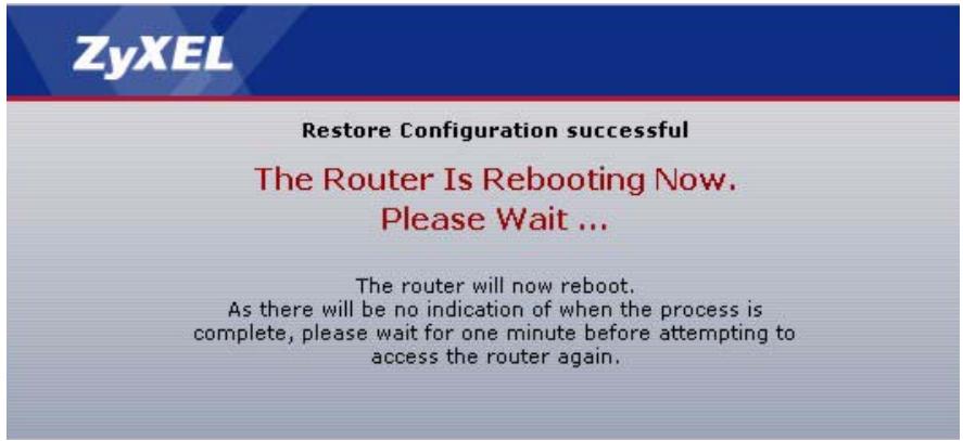
Figure 129 Configuration Upload Successful
The P-793H v2 automatically restarts in this time causing a temporary network disconnect. In some operating systems, you may see the following icon on your desktop.
Figure 130 Network Temporarily Disconnected
If you uploaded the default configuration file you may need to change the IP address of your computer to be in the same subnet as that of the default device IP address (192.168.1.1). See Appendix C on page 429 for details on how to set up your computer's IP address.
If the upload was not successful, the following screen will appear. Click Return to go back to the Configuration screen.
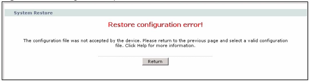
Figure 131 Configuration Upload Error
Reset to Factory Defaults
Click the Reset button to clear all user-entered configuration information and return the P-793H v2 to its factory defaults. The following warning screen appears.

Figure 132 Reset Warning Message
Figure 133 Reset In Process Message
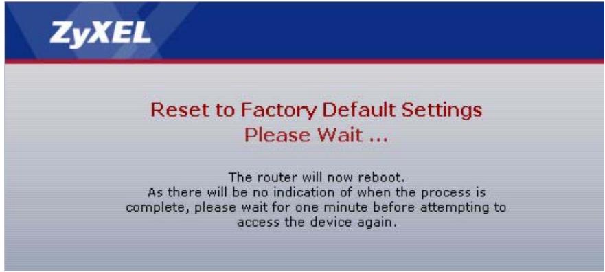
You can also press the RESET button on the rear panel to reset the factory defaults of your P-793H v2. Refer to Section 1.5 on page 41 for more information on the RESET button.
21.4 The Restart Screen
System restart allows you to reboot the P-793H v2 remotely without turning the power off. You may need to do this if the P-793H v2 hangs, for example.
Click Maintenance > Tools > Restart. Click Restart to have the P-793H v2 reboot. This does not affect the P-793H v2's configuration.
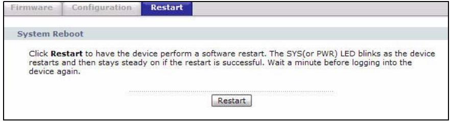
Figure 134 Maintenance > Tools > Restart
22.1 Overview
These read-only screens display information to help you identify problems with the P-793H v2.
22.1.1 What You Can Do in the Diagnostic Screens
- Use the General screen (Section 22.2 on page 297) to ping an IP address.
- Use the DSL Line screen (Section 22.3 on page 298) to view the DSL line statistics and reset the ADSL line.
22.2 The General Diagnostic Screen
Use this screen to ping an IP address. Click Maintenance > Diagnostic to open the screen shown next.
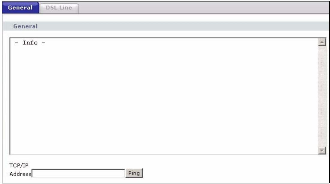
Figure 135 Maintenance > Diagnostic > General
The following table describes the fields in this screen.
Table 104 Maintenance > Diagnostic > General
| LABEL | DESCRIPTION |
| TCP/IP Address | Type the IP address of a computer that you want to ping in order to test a connection. |
| Ping | Click this to ping the IP address that you entered. |
22.3 The DSL Line Diagnostic Screen
Use this screen to view the DSL line statistics and reset the ADSL line. Click Maintenance > Diagnostic > DSL Line to open the screen shown next.
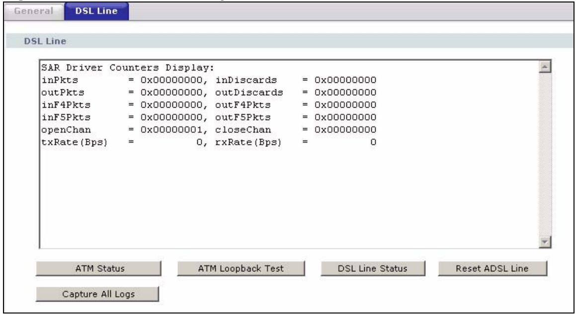
Figure 136 Maintenance > Diagnostic > DSL Line
The following table describes the fields in this screen.
Table 105 Maintenance > Diagnostic > DSL Line
| LABEL | DESCRIPTION |
| ATM Status | Click this to view your DSL connection's Asynchronous Transfer Mode (ATM) statistics. ATM is a networking technology that provides high-speed data transfer. ATM uses fixed-size packets of information called cells. With ATM, a high QoS (Quality of Service) can be guaranteed.The (Segmentation and Reassembly) SAR driver translates packets into ATM cells. It also receives ATM cells and reassembles them into packets.These counters are set back to zero whenever the device starts up.inPkts is the number of good ATM cells that have been received.inDiscards is the number of received ATM cells that were rejected.outPkts is the number of ATM cells that have been sent.outDiscards is the number of ATM cells sent that were rejected.inF4Pkts is the number of ATM Operations, Administration, and Management (OAM) F4 cells that have been received. See ITU recommendation I.610 for more on OAM for ATM.outF4Pkts is the number of ATM OAM F4 cells that have been sent.inF5Pkts is the number of ATM OAM F5 cells that have been received.outF5Pkts is the number of ATM OAM F5 cells that have been sent.openChan is the number of times that the P-793H v2 has opened a logical DSL channel.closeChan is the number of times that the P-793H v2 has closed a logical DSL channel.txRate is the number of bytes transmitted per second.rxRate is the number of bytes received per second. |
| ATM Loopback Test | Click this to start the ATM loopback test. Make sure you have configured at least one PVC with proper VPIs/VCIs before you begin this test. The P-793H v2 sends an OAM F5 packet to the DSLAM/ATM switch and then returns it (loops it back) to the P-793H v2. The ATM loopback test is useful for troubleshooting problems with the DSLAM and ATM network. |
| DSL Line Status | Click this to view statistics about the DSL connections. noise margin downstream is the signal to noise ratio for the downstream part of the connection (coming into the P-793H v2 from the ISP). It is measured in decibels. The higher the number the more signal and less noise there is. output power upstream is the amount of power (in decibels) that the P-793H v2 is using to transmit to the ISP. attenuation downstream is the reduction in amplitude (in decibels) of the DSL signal coming into the P-793H v2 from the ISP. Discrete Multi-Tone (DMT) modulation divides up a line's bandwidth into sub-carriers (sub-channels) of 4.3125 KHz each called tones. The rest of the display is the line's bit allocation. This is displayed as the number (in hexadecimal format) of bits transmitted for each tone. This can be used to determine the quality of the connection, whether a given sub-carrier loop has sufficient margins to support certain ADSL transmission rates, and possibly to determine whether particular specific types of interference or line attenuation exist. Refer to the ITU-T G.992.1 recommendation for more information on DMT. The better (or shorter) the line, the higher the number of bits transmitted for a DMT tone. The maximum number of bits that can be transmitted per DMT tone is 15. There will be some tones without any bits as there has to be space between the upstream and downstream channels. |
| Reset ADSL Line | Click this to reinitialize the ADSL line. The large text box above then displays the progress and results of this operation, for example: "Start to reset ADSL Loading ADSL modem F/W... Reset ADSL Line Successfully!" |
| Capture All Logs | Click this to display information and statistics about your P-793H v2's ATM statistics, DSL connection statistics, DHCP settings, firmware version, WAN and gateway IP address, VPI/VCI and LAN IP address. |
Introducing the SMT
The System Management Terminal (SMT) provides a text-based, menu-driven console to manage the P-793H v2. This chapter describes how to access the SMT and then provides an overview of its menus.
23.1 Accessing the SMT
Use Telnet to access the SMT. Follow these steps.
1 In Windows, click Start > Run.
2 Type "telnet w.x.y.z", and click OK.
w.x.y.z is the IP address of the P-793H v2; the default address is 192.168.1.1.
The P-793H v2 prompts you for the password.
Figure 137 Login Screen
Password : xxxx
3 Enter the password. The default password is 1234. As you type the password, the screen displays an asterisk ** for each character you type.
4 After you enter the password, the SMT main menu appears, as shown next.
Note: Use menu 23.1 to change the password.
Figure 138 SMT Main Menu
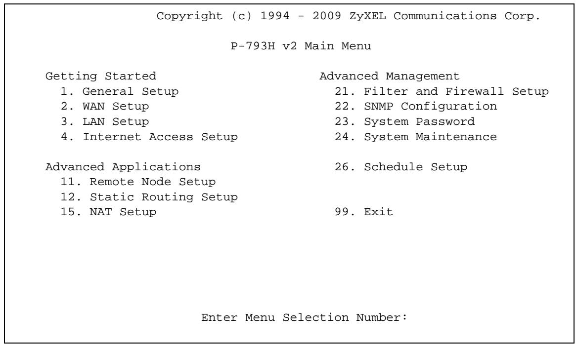
Note: There is an inactivity timeout, and the default value is ten minutes. If there is no activity for longer than this, your P-793H v2 will automatically log you out. You will then have to telnet into the P-793H v2 again. You can use the web configurator or the CI commands (menu 24.8) to change the inactivity timeout period.
23.2 SMT Menu Items
The following table provides an overview of each menu item.
Table 106 Main Menu Summary
| MENU | FUNCTION |
| 1 General Setup | Use this menu to set up device mode, dynamic DNS and administrative information. |
| 2 WAN Setup | Use this menu to configure the DSL connection, and traffic redirect interface. |
| 3 LAN Setup | Use this to apply LAN filters, configure LAN DHCP and TCP/IP settings, and to allow or block layer-2 traffic between each pair of ports. |
| 4 Internet Access Setup | Use this menu to configure your Internet connection. |
Table 106 Main Menu Summary
| MENU | FUNCTION |
| 11 Remote Node Setup | Use this menu to configure detailed remote node settings (for example, your ISP is a remote node) as well as apply filters. |
| 12 Static Routing Setup | Use this menu to configure IP and bridge (MAC) static routes. |
| 15 NAT Setup | Use this menu to configure Network Address Translation (NAT) on the P-793H v2. |
| 21 Filter and Firewall Setup | Use this menu to configure filters and to activate or deactivate the firewall. |
| 22 SNMP Configuration | Use this menu to configure SNMP. |
| 23 System Password | Use this menu to change your password. |
| 24 System Maintenance | Use this menu for comprehensive system maintenance, from looking at the system status to uploading firmware. You can also access the Command Interface (CI). |
| 26 Schedule Setup | Use this menu to configure schedule sets. |
| 99 Exit | Use this menu to exit the SMT. |
The following table gives you an overview of the various SMT menus.
Table 107 SMT Menus Overview
| MENUS | SUB MENUS | ||
| 1 General Setup | 1.1 Configure Dynamic DNS | ||
| 2 WAN Setup | 2.1 Traffic Redirect Setup | ||
| 3 LAN Setup | 3.1 LAN Port Filter Setup | ||
| 3.2 TCP/IP and DHCP Setup | 3.2.1 IP Alias Setup | ||
| 4 Internet Access Setup | |||
| 11 Remote Node Setup | 11.1 Remote Node Profile | 11.1.3 Remote Node Network Layer Options | |
| 11.1.5 Remote Node Filter | |||
| 11.1.6 Remote Node ATM Layer Options | |||
| 12 Static Route Setup | 12.1 IP Static Route Setup | 12.1.1 Edit IP Static Route | |
| 12.3 Bridge Static Route Setup | 12.3.1 Edit Bridge Static Route | ||
| 15 NAT Setup | 15.1 Address Mapping Sets | 15.1.x Address Mapping Rules | 15.1.x.x Address Mapping Rule |
| 15.2 NAT Server Sets | 15.2.x NAT Server Setup | ||
| 21 Filter and Firewall Setup | 21.1 Filter Set Configuration | 21.1.x Filter Rules Summary | 21.1.x.x Generic Filter Rule |
| 21.1.x.x TCP/IP Filter Rule | |||
| 21.2 Firewall Setup | |||
| 22 SNMP Configuration | |||
| 23 System Password | |||
| 24 System Maintenance | 24.1 System Maintenance - Status | ||
| 24.2 System Information and Console Port Speed | 24.2.1 System Maintenance - Information | ||
| 24.2.2 System Maintenance - Change Console Port Speed | |||
| 24.3 System Maintenance - Log and Trace | 24.3.1 View Error Log | ||
| 24.3.2 System Maintenance - UNIX Syslog | |||
| 24.4 System Maintenance - Diagnostic | |||
| 24.5 Backup Configuration | |||
| 24.6 Restore Configuration | |||
| 24.7 System Maintenance - Upload Firmware | 24.7.1 System Maintenance - Upload System Firmware | ||
| 24.7.2 System Maintenance - Upload System Configuration File | |||
| 24.8 Command Interpreter Mode | |||
| 24.9 System Maintenance - Call Control23 | 24.9.1 Budget Management | ||
| 24.10 System Maintenance - Time and Date Setting | |||
| 24.11 Remote Management Control | |||
| 26 Schedule Setup | 26.1 Schedule Set Setup | ||
23.3 Navigating the SMT Interface
You should be familiar with the following operations before you try to use the SMT to modify the configuration.
Table 108 Main Menu Commands
| OPERATION | KEYSTROKE | DESCRIPTION |
| Move down to another menu | [ENTER] | To move forward to a submenu, type in the number of the desired submenu and press [ENTER]. |
| Move up to a previous menu | [ESC] | Press [ESC] to move back to the previous menu. |
| Move to a "hidden" menu | Press [SPACE BAR] to change No to Yes then press [ENTER]. | Fields beginning with "Edit" lead to hidden menus and have a default setting of No. Press [SPACE BAR] once to change No to Yes, then press [ENTER] to go to the "hidden" menu. |
| Move the cursor | [ENTER] or [UP]/[DOWN] arrow keys. | Within a menu, press [ENTER] to move to the next field. You can also use the [UP]/[DOWN] arrow keys to move to the previous and the next field, respectively. |
| Entering information | Type in or press [SPACE BAR], then press [ENTER]. | You need to fill in two types of fields. The first requires you to type in the appropriate information. The second allows you to cycle through the available choices by pressing [SPACE BAR]. |
| Required fields | <?> or ChangeMe | All fields with the symbol <?> must be filled in order to be able to save the new configuration. All fields with ChangeMe must not be left blank in order to be able to save the new configuration. |
| N/A fields | <N/A> | Some of the fields in the SMT will show a <N/A>. This symbol refers to an option that is Not Applicable. |
| Save your configuration | [ENTER] | Save your configuration by pressing [ENTER] at the message "Press ENTER to confirm or ESC to cancel". Saving the data on the screen will take you, in most cases to the previous menu. |
| Exit the SMT | Type 99, then press [ENTER]. | Type 99 at the main menu prompt and press [ENTER] to exit the SMT interface. |
Use this menu to set up device mode, dynamic DNS and administrative information.
24.1 Configuring General Setup
1 Enter 1 in the main menu to open Menu 1 - General Setup.
2 The Menu 1 - General Setup screen appears, as shown next. Fill in the required fields.
Figure 139 Menu 1: General Setup
Menu 1 - General Setup System Name= P-793H v2 Location= Contact Person's Name= Domain Name= First DNS Server= 0.0.0.0 Secondary DNS Server= 0.0.0.0 Third DNS Server= 0.0.0.0 Edit Dynamic DNS= No Route IP= Yes Bridge= No
The following table describes the fields in this menu.
Table 109 Menu 1: General Setup
| FIELD | DESCRIPTION |
| System Name | Choose a descriptive name for identification purposes. It is recommended you enter your computer's "Computer name" in this field. This name can be up to 30 alphanumeric characters long. Spaces are not allowed, but dashes "-" and underscores "-" are accepted. |
| Location | Enter a descriptive name for the place where the P-793H v2 is located. You can enter up to 31 characters, or you can leave this field blank. |
| Contact Person's Name | Enter the name of the person to contact for questions about the P-793H v2. You can enter up to 30 characters, or you can leave this field blank. |
| Domain Name | Enter the domain name (if you know it) here. If you leave this field blank, the ISP may assign a domain name via DHCP. You can go to menu 24.8 and type "sys domain name" to see the current domain name used by your router.The domain name entered by you is given priority over the ISP assigned domain name. If you want to clear this field just press [SPACE BAR] and then [ENTER]. |
| Edit Dynamic DNS | Press [SPACE BAR] and then [ENTER] to select Yes or No (default).Select Yes to configure Menu 1.1: Configure Dynamic DNS discussed next. |
| Route IP | Select Yes to enable IP-based routing in the P-793H v2. This is not effective for a specific remote node unless you enable IP-based routing in the remote node too. See Menu 11.1: Remote Node Profile (nodes 1-7) in Section 28.3 on page 326.You should enable Route IP, Bridge, or both in this screen. If you disable Route IP and Bridge, the device does not send traffic between the LAN ports and remote node. |
| Bridge345 | If Route IP is Yes, select Yes in this field to enable bridging in the P-793H v2 for protocols that are not supported by IP-based routing (for example, SNA).If Route IP is No, select Yes in this field to enable bridging in the P-793H v2 for all protocols.In either case, this setting is not effective for a specific remote node unless you enable bridging in the remote node too. See Menu 11.1: Remote Node Profile (nodes 1-7) in Section 28.3 on page 326.You should enable Route IP, Bridge, or both in this screen. If you disable Route IP and Bridge, the device does not send traffic between the LAN ports and remote node. |
| When you have completed this menu, press [ENTER] at the prompt "Press ENTER to Confirm..." to save your configuration, or press [ESC] at any time to cancel. | |
24.1.1 Configuring Dynamic DNS
To configure Dynamic DNS, set the P-793H v2 to router mode in menu 1 or in the MAINTENANCE Device Mode screen and go to Menu 1 - General Setup and
press [SPACE BAR] to select Yes in the Edit Dynamic DNS field. Press [ENTER] to display Menu 1.1 - Configure Dynamic DNS (shown next).
Figure 140 Menu 1.1: Configure Dynamic DNS
Menu 1.1 - Configure Dynamic DNS Service Provider= WWW.DynDNS.ORG Active= No DDNSType= DynamicDNS Host 1= Host 2= Host 3=Username= Password=***** Enable Wildcard Option=No Enable Off Line Option= N/A IP Address Update Policy: DDNS Server Auto Detect IP Address= No Use Specified IP Address= No Use IP Address= N/A
Follow the instructions in the next table to configure Dynamic DNS parameters.
Table 110 Menu 1.1: Configure Dynamic DNS
| FIELD | DESCRIPTION |
| Service Provider | This is the name of your Dynamic DNS service provider. |
| Active | Press [SPACE BAR] to select Yes and then press [ENTER] to make dynamic DNS active. |
| DDNSType | Press [SPACE BAR] and then [ENTER] to select DynamicDNS if you have the Dynamic DNS service. Select StaticDNS if you have the Static DNS service. Select CustomDNS if you have the Custom DNS service. |
| Host 1-3 | Enter up to three host names in these fields. |
| Username | Enter your user name. |
| Password | Enter the password assigned to you. |
| Enable Wildcard Option | Your P-793H v2 supports DYNDNS Wildcard. Press [SPACE BAR] and then [ENTER] to select Yes or No. This field is N/A when you choose DDNS client as your service provider. |
| Enable Off Line Option | This field is only available when CustomDNS is selected in the DDNS Type field. Press [SPACE BAR] and then [ENTER] to select Yes. When Yes is selected, http://www.dyndns.org/ traffic is redirected to a URL that you have previously specified (see www.dyndns.org for details). |
Table 110 Menu 1.1: Configure Dynamic DNS
| FIELD | DESCRIPTION |
| IP Address Update Policy: | You can select Yes in either the DDNS Server Auto Detect IP Address field (recommended) or the Use Specified IP Address field, but not both.With the DDNS Server Auto Detect IP Address and Use Specified IP Address fields both set to No, the DDNS server automatically updates the IP address of the host name(s) with the P-793H v2's WAN IP address.DDNS does not work with a private IP address. When both fields are set to No, the P-793H v2 must have a public WAN IP address in order for DDNS to work. |
| DDNS Server Auto Detect IP Address | Only select this option when there are one or more NAT routers between the P-793H v2 and the DDNS server. Press [SPACE BAR] to select Yes and then press [ENTER] to have the DDNS server automatically detect and use the IP address of the NAT router that has a public IP address.Note: The DDNS server may not be able to detect the proper IP address if there is an HTTP proxy server between the P-793H v2 and the DDNS server. |
| Use Specified IP Address | Press [SPACE BAR] to select Yes and then press [ENTER] to update the IP address of the host name(s) to the IP address specified below.Only select Yes if the P-793H v2 uses or is behind a static public IP address. |
| Use IP Address | Enter the static public IP address if you select Yes in the Use Specified IP Address field. |
| When you have completed this menu, press [ENTER] at the prompt "Press ENTER to Confirm..." to save your configuration, or press [ESC] at any time to cancel. | |
Use this menu to configure the DSL connection, and traffic redirect interface.
25.1 WAN Setup
From the main menu, enter 2 to open menu 2.
Figure 141 Menu 2: WAN Setup
Menu 2 - WAN Setup
Service Mode= 2wire DSL Mode = ATM
Service Type= Server
Rate Adaption= Disable Rate Adaption= N/A
        Transfer Max Rate(Kbps) = 5696 Transfer Max Rate(Kbps) = N/A
        Transfer Min Rate(Kbps) = 192 Transfer Min Rate(Kbps) = N/A
        Standard Mode= ETSI(ANNEX_B) Standard Mode= N/A
Wan Backup Setup:
Check Mechanism = ICMP
Check WAN IP Address1 = 0.0.0.0
Check WAN IP Address2 = 0.0.0.0
Check WAN IP Address3 = 0.0.0.0
        KeepAlive Fail Tolerance = 31
        Recovery Interval(sec) = 3
        ICMP Timeout(sec) = 9677
        Traffic Redirect = No
The following table describes the fields in this screen.
Table 111 Menu 2: WAN Setup
| FIELD | DESCRIPTION |
| Service Mode | Press [SPACE BAR] to indicate whether the P-793H v2 should use 2-wire or 4-wire mode for the DSL connection. This is related to the phone line you use and affects the maximum speed of the connection. In 2-wire mode, the maximum data rate is up to 5.69 Mbps, while in 4-wire mode, the maximum data rate us up to 11.38 Mbps. See Section 25.1.1 on page 313 for information on 2wire-2line service mode. |
| DSL Mode | Press [SPACE BAR] to select the transfer mode you want to use.PTM (Packet Transfer Mode): The P-793H v2 uses the SHDSL technology for data transmission over the DSL port.ATM (Asynchronous Transfer Mode): The P-793H v2 uses the ADSL technology for data transmission over the DSL port. |
| Service Type | Press [SPACE BAR] to indicate whether the P-793H v2 is the server or the client in the DSL connection. Select Server if this P-793H v2 is the server in a point-to-point application. (See Chapter 5 on page 67.) Otherwise, select Client. |
| Rate Adaption | This field is configurable if Service Type is Server. Press [SPACE BAR] to let the P-793H v2 adjust the speed of its connection to that of the other device. |
| Transfer Max Rate(Kbps) | This field is enabled if Service Type is Server. Press [SPACE BAR] to set the maximum rate at which the P-793H v2 sends and receives information. If you enable Rate Adaption, the P-793H v2 adjusts to the speed of the other device and may exceed this rate. |
| Transfer Min Rate(Kbps) | This field is enabled if Service Type is Server. Press [SPACE BAR] to set the minimum rate at which the P-793H v2 sends and receives information. If you enable Rate Adaption, the P-793H v2 adjusts to the speed of the other device and may transfer information at less than this rate. |
| Standard Mode | This field is enabled if Service Type is Server. Press [SPACE BAR] to select the operational mode the P-793H v2 uses in the DSL connection. |
| Wan Backup Setup | |
| Check Mechanism | Select the method that the P-793H v2 uses to check the DSL connection. Select DSL Link to have the P-793H v2 check if the connection to the DSLAM is up. Select ICMP to have the P-793H v2 periodically ping the IP addresses configured in the Check WAN IP Address fields. |
| Check WAN IP Address1 | Configure this field to test your P-793H v2's WAN accessibility. Type the IP address of up to three reliable, nearby computers (for example, your ISP's DNS server address). |
| Check WAN IP Address2 | Note: If you activate either traffic redirect or dial backup, you must configure at least one IP address here. |
| Check WAN IP Address3 | When using a WAN backup connection, the P-793H v2 periodically pings the addresses configured here and uses the other WAN backup connection (if configured) if there is no response. |
| KeepAlive Fail Tolerance | Type the number of times (2 recommended) that your P-793H v2 may ping the IP addresses configured in the Check WAN IP Address field without getting a response before switching to a WAN backup connection (or a different WAN backup connection). |
| Recovery Interval(sec) | When the P-793H v2 is using a lower priority connection (usually a WAN backup connection), it periodically checks to whether or not it can use a higher priority connection. Type the number of seconds (30 recommended) for the P-793H v2 to wait between checks. Allow more time if your destination IP address handles lots of traffic. |
| ICMP Timeout(sec) | Type the number of seconds (3 recommended) for your P-793H v2 to wait for a ping response from one of the IP addresses in the Check WAN IP Address field before timing out the request. The WAN connection is considered "down" after the P-793H v2 times out the number of times specified in the Fail Tolerance field. Use a higher value in this field if your network is busy or congested. |
| Traffic Redirect | Press [SPACE BAR] to select Yes and then press [ENTER] to activate traffic redirect and to edit its settings. |
| When you have completed this menu, press [ENTER] at the prompt "Press ENTER to Confirm..." to save your configuration, or press [ESC] at any time to cancel. | |
25.1.1 2wire-2line Service Mode
From the main menu, enter 2 to open menu 2, then select 2wire-2line in the Service Mode field to see the screen as shown below.
Figure 142 Menu 2: 2wire-2line Service Mode
Menu 2 - WAN Setup
Service Mode= 2wire-2line
Service Type= N/A
Rate Adaption= Disable Rate Adaption= Enable
    Transfier Max Rate(Kbps)= 4480 Transfer Max Rate(Kbps)= 5696
    Transfier Min Rate(Kbps)= 4480 Transfer Min Rate(Kbps)= 3200
    Standard Mode= ANSI(ANNEX_A) Standard Mode= ANSI(ANNEX_A)
Wan Backup Setup:
Check Mechanism = DSL Link
Check WAN IP Address1 = 0.0.0.0
Check WAN IP Address2 = 0.0.0.0
Check WAN IP Address3 = 0.0.0.0
KeepAlive Fail Tolerance = 0
Recovery Interval(sec) = 0
ICMP Timeout(sec) = 0
Traffic Redirect = No
The following table describes the fields in this screen.
Table 112 Menu 2: 2wire-2line Service Mode
| FIELD | DESCRIPTION |
| Service Mode | Press [SPACE BAR] to select 2wire-2line service mode. This means you are establishing a point-to-2point connection. In 2wire-2line mode, the maximum data rate is up to 5.69 Mbps for each DSL connection. |
| Service Type | The P-793H v2 automatically acts as a server in 2wire-2line mode. |
| Rate Adaption | The field on the left refers to DSL 1 connection and the field on the right refers to DSL 2 connection. Press [SPACE BAR] to let the P-793H v2 adjust the speed of its connection to that of the other device. |
| Transfer Max Rate(Kbps) | The field on the left refers to DSL 1 connection and the field on the right refers to DSL 2 connection. Press [SPACE BAR] to set the maximum rate at which the P-793H v2 sends and receives information. If you enable Rate Adaption, the P-793H v2 adjusts to the speed of the other device and may exceed this rate. |
| Transfer Min Rate(Kbps) | The field on the left refers to DSL 1 connection and the field on the right refers to DSL 2 connection. Press [SPACE BAR] to set the minimum rate at which the P-793H v2 sends and receives information. If you enable Rate Adaption, the P-793H v2 adjusts to the speed of the other device and may transfer information at less than this rate. |
| Standard Mode | The field on the left refers to DSL 1 connection and the field on the right refers to DSL 2 connection. Press [SPACE BAR] to select the operational mode the P-793H v2 uses in the DSL connection. |
| Wan Backup Setup | |
| Check Mechanism | Select the method that the P-793H v2 uses to check the DSL connection. Select DSL Link to have the P-793H v2 check if the connection to the DSLAM is up. Select ICMP to have the P-793H v2 periodically ping the IP addresses configured in the Check WAN IP Address fields. |
| Check WAN IP Address1 | |
| Check WAN IP Address2 | |
| Check WAN IP Address3 | |
| KeepAlive Fail Tolerance | Type the number of times (2 recommended) that your P-793H v2 may ping the IP addresses configured in the Check WAN IP Address field without getting a response before switching to a WAN backup connection (or a different WAN backup connection). |
| Recovery Interval(sec) | When the P-793H v2 is using a lower priority connection (usually a WAN backup connection), it periodically checks to whether or not it can use a higher priority connection. Type the number of seconds (30 recommended) for the P-793H v2 to wait between checks. Allow more time if your destination IP address handles lots of traffic. |
| ICMP Timeout(sec) | Type the number of seconds (3 recommended) for your P-793H v2 to wait for a ping response from one of the IP addresses in the Check WAN IP Address field before timing out the request. The WAN connection is considered "down" after the P-793H v2 times out the number of times specified in the Fail Tolerance field. Use a higher value in this field if your network is busy or congested. |
| Traffic Redirect | This feature is disabled in 2wire-2line service mode. |
| When you have completed this menu, press [ENTER] at the prompt "Press ENTER to Confirm..." to save your configuration, or press [ESC] at any time to cancel. | |
25.2 Configuring Traffic Redirect
From the main menu, in menu 2, select Yes in Traffic Redirect, and then press [ENTER].

Figure 143 Menu 2.1: Traffic Redirect Setup
The following table describes the fields in this menu.
Table 113 Menu 2.1: Traffic Redirect Setup
| FIELD | DESCRIPTION |
| Active | Use this field to turn the traffic redirect feature on (Yes) or off (No). |
| Configuration | |
| Backup Gateway IP Address | Type the IP address of your backup gateway in dotted decimal notation. The P-793H v2 automatically forwards traffic to this IP address if the P-793H v2's Internet connection terminates. |
| Metric | This field sets this route's priority among the routes the P-793H v2 uses. The metric represents the "cost of transmission". A router determines the best route for transmission by choosing a path with the lowest "cost". RIP routing uses hop count as the measurement of cost, with a minimum of "1" for directly connected networks. The number must be between "1" and "15"; a number greater than "15" means the link is down. The smaller the number, the lower the "cost". |
| When you have completed this menu, press [ENTER] at the prompt "Press ENTER to Confirm..." to save your configuration, or press [ESC] at any time to cancel. | |
Use this to apply LAN filters, configure LAN DHCP and TCP/IP settings, and to activate or deactivate VLAN on each LAN port.
26.1 Accessing the LAN Menus
From the main menu, enter 3 to open Menu 3 - LAN Setup.
Figure 144 Menu 3: LAN Setup
Menu 3 - LAN Setup
1. LAN Port Filter Setup
2. TCP/IP and DHCP Setup
26.2 LAN Port Filter Setup
This menu allows you to specify the filter sets that you wish to apply to the LAN traffic. You seldom need to filter the LAN traffic, however, the filter sets may be useful to block certain packets, reduce traffic and prevent security breaches.
Figure 145 Menu 3.1: LAN Port Filter Setup
Menu 3.1 - LAN Port Filter Setup
Input Filter Sets:
    protocol filters=
    device filters=
Output Filter Sets:
    protocol filters=
    device filters=
26.3 TCP/IP and DHCP Setup Menu
From the main menu, enter 3 to open Menu 3 - LAN Setup to configure TCP/IP (RFC 1155) and DHCP setup. From menu 3, select the submenu option TCP/IP and DHCP Setup and press [ENTER]. The screen now displays Menu 3.2 - TCP/IP and DHCP Ethernet Setup, as shown next. Not all fields are available on all models.
Figure 146 Menu 3.2: TCP/IP and DHCP Ethernet Setup
Menu 3.2 - TCP/IP and DHCP Setup
DHCP= Server
Client IP Pool Starting Address= 192.168.1.33
Size of Client IP Pool= 32
First DNS Server= 0.0.0.0
Secondary DNS Server= 0.0.0.0
Third DNS Server= 0.0.0.0
DHCP Server Address= N/A
TCP/IP Setup:
IP Address= 192.168.1.1
IP Subnet Mask= 255.255.255.0
RIP Direction= Both
Version= RIP-2B
Multicast= IGMP-v2
IP Policies=
Edit IP Alias= No
Follow the instructions in the next table to configure these fields.
Table 114 Menu 3.2: TCP/IP and DHCP Ethernet Setup
| FIELD | DESCRIPTION |
| DHCP Setup | |
| DHCP | This field enables/disables the DHCP server. If set to Server, your P-793H v2 will act as a DHCP server. You should configure the rest of the fields in this section except for Remote DHCP Server. If set to Relay, the P-793H v2 acts as a surrogate DHCP server and relays requests and responses between the remote server and the clients. The Remote DHCP Server needs to be set. If set to None, the DHCP server will be disabled. |
| Client IP Pool Starting Address: | This field specifies the first of the contiguous addresses in the IP address pool. |
| Size of Client IP Pool | This field specifies the size, or count of the IP address pool. |
| First DNS Server | The P-793H v2 passes a DNS (Domain Name System) server IP address (in the order you specify here) to the DHCP clients. |
| Secondary DNS Server | Select From ISP if your ISP dynamically assigns DNS server information (and the P-793H v2's WAN IP address). The IP Address field below displays the (read-only) DNS server IP address that the ISP assigns. |
| Third DNS Server | Select User-Defined if you have the IP address of a DNS server. Enter the DNS server's IP address in the IP Address field below. If you chose User-Defined, but leave the IP address set to 0.0.0.0, User-Defined changes to None after you save your changes. If you set a second choice to User-Defined, and enter the same IP address, the second User-Defined changes to None after you save your changes. |
| Select DNS Relay to have the P-793H v2 act as a DNS proxy. The P-793H v2's LAN IP address displays in the IP Address field below (read-only). The P-793H v2 tells the DHCP clients on the LAN that the P-793H v2 itself is the DNS server. When a computer on the LAN sends a DNS query to the P-793H v2, the P-793H v2 forwards the query to the P-793H v2's system DNS server (configured in menu 1) and relays the response back to the computer. You can only select DNS Relay for one of the three servers; if you select DNS Relay for a second or third DNS server, that choice changes to None after you save your changes. | |
| Select None if you do not want to configure DNS servers. If you do not configure a DNS server, you must know the IP address of a machine in order to access it. | |
| DHCP Server Address | If Relay is selected in the DHCP field above, then type the IP address of the actual remote DHCP server here. |
| TCP/IP Setup: | |
| IP Address | Enter the LAN IP address of your P-793H v2 in dotted decimal notation |
| IP Subnet Mask | Your P-793H v2 will automatically calculate the subnet mask based on the IP address that you assign. Unless you are implementing subnetting, use the subnet mask computed by the P-793H v2. |
| RIP Direction | Press [SPACE BAR] and then [ENTER] to select the RIP direction. Options are: Both, In Only, Out Only or None. |
| Version | Press [SPACE BAR] and then [ENTER] to select the RIP version. Options are: RIP-1, RIP-2B or RIP-2M. |
| Multicast | IGMP (Internet Group Multicast Protocol) is a session-layer protocol used to establish membership in a Multicast group. The P-793H v2 supports both IGMP version 1 (IGMP-v1) and version 2 (IGMP-v2). Press [SPACE BAR] and then [ENTER] to enable IP Multicasting or select None (default) to disable it. |
| Edit IP Alias | The P-793H v2 supports three logical LAN interfaces via its single physical Ethernet interface with the P-793H v2 itself as the gateway for each LAN network. Press [SPACE BAR] to select Yes and then press [ENTER] to display menu 3.2.1. |
| When you have completed this menu, press [ENTER] at the prompt [Press ENTER to Confirm...] to save your configuration, or press [ESC] at any time to cancel. | |
26.4 LAN IP Alias
Use menu 3.2 to configure the first network, and you use menu 3.2.1 to configure the other two networks. Move the cursor to the Edit IP Alias field, press [SPACE BAR] to choose Yes and press [ENTER] to configure the second and third network.
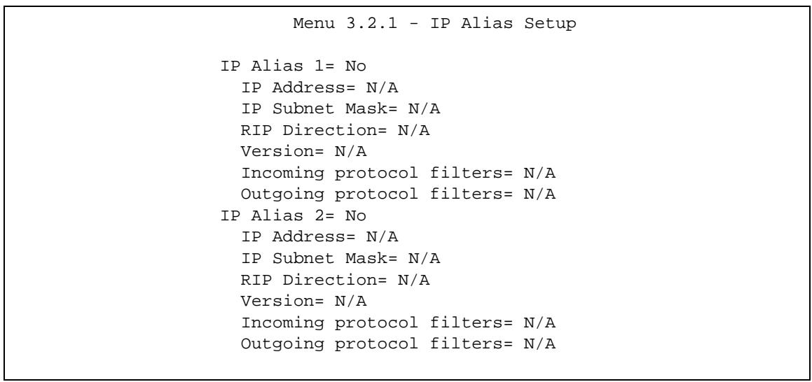
Figure 147 Menu 3.2.1: IP Alias Setup
Use the instructions in the following table to configure IP alias parameters.
Table 115 Menu 3.2.1: IP Alias Setup
| FIELD | DESCRIPTION |
| IP Alias 1, 2 | Choose Yes to configure the LAN network for the P-793H v2. |
| IP Address | Enter the IP address of your P-793H v2 in dotted decimal notation. |
| IP Subnet Mask | Your P-793H v2 will automatically calculate the subnet mask based on the IP address that you assign. Unless you are implementing subnetting, use the subnet mask computed by the P-793H v2. |
| RIP Direction | Press [SPACE BAR] and then [ENTER] to select the RIP direction. Options are Both, In Only, Out Only or None. |
| Version | Press [SPACE BAR] and then [ENTER] to select the RIP version. Options are RIP-1, RIP-2B or RIP-2M. |
| Incoming protocol filters | Enter the filter set(s) you wish to apply to the incoming traffic between this node and the P-793H v2. |
| Outgoing protocol filters | Enter the filter set(s) you wish to apply to the outgoing traffic between this node and the P-793H v2. |
| When you have completed this menu, press [ENTER] at the prompt [Press ENTER to Confirm...] to save your configuration, or press [ESC] at any time to cancel. | |
Internet Access Setup
Use this menu to configure your Internet connection. Use information from your ISP along with the instructions in this chapter to set up your P-793H v2 to access the Internet. Contact your ISP to determine what encapsulation type you should use.
27.1 Internet Access Setup
Enter 4 in the main menu.
Figure 148 Menu 4: Internet Access Setup
Menu 4 - Internet Access Setup
ISP's Name= MyISP
Encapsulation= ENET ENCAP
Multiplexing= LLC-based
VPI#=0
VCI#=33
ATM QoS Type= UBR
Peak Cell Rate (PCR)=0
Sustain Cell Rate (SCR)=0
Maximum Burst Size (MBS)=0
My Login=N/A
My Password=N/A
ENET ENCAP Gateway=0.0.0.0
IP Address Assignment=Static
IP Address=0.0.0.0
Network Address Translation= SUA Only
Address Mapping Set=N/A
The following table describes the fields in this menu.
Table 116 Menu 4: Internet Access Setup
| FIELD | DESCRIPTION |
| ISP's Name | Enter a descriptive name for your ISP for identification purposes. |
| Encapsulation | Press [SPACE BAR] and then press [ENTER] to select the type of encapsulation your ISP uses. |
| Multiplexing | Press [SPACE BAR] to select the method of multiplexing used by your ISP. Choices are VC-based or LLC-based. |
| VPI | VPI (Virtual Path Identifier) and VCI (Virtual Channel Identifier) define a virtual circuit. The valid range for the VPI is 0 to 255. Enter the VPI assigned to you. |
| VCI | The valid range for the VCI is 32 to 65535 (0 to 31 is reserved for local management of ATM traffic). Enter the VCI assigned to you. |
| ATM QoS Type | Select CBR (Constant Bit Rate) to specify fixed (always-on) bandwidth for voice or data traffic. Select UBR (Unspecified Bit Rate) for applications that are non-time sensitive, such as e-mail. Select VBR (Variable Bit Rate) for bursty traffic and bandwidth sharing with other applications. |
| Peak Cell Rate (PCR) | Divide the DSL line rate (bps) by 424 (the size of an ATM cell) to find the Peak Cell Rate (PCR). This is the maximum rate at which the sender can send cells. Type the PCR here. |
| Sustain Cell Rate (SCR) | The Sustain Cell Rate (SCR) sets the average cell rate (long-term) that can be transmitted. Type the SCR, which must be less than the PCR. Note that system default is 0 cells/sec. |
| Maximum Burst Size (MBS) | Maximum Burst Size (MBS) refers to the maximum number of cells that can be sent at the peak rate. Type the MBS, which is less than 65535. |
| My Login | (PPPoE and PPPoA only) Enter the login name given to you by your ISP. |
| My Password | (PPPoE and PPPoA only) Type your password again for confirmation. |
| ENET ENCAP Gateway | (ENET ENCAP only) Enter the gateway IP address provided by your ISP. |
| Idle Timeout (sec) | (PPPoE and PPPoA only) Specify an idle time-out. The default setting is 0, which means the Internet session will not timeout. |
| IP Address Assignment | If your ISP did not assign you a fixed IP address, press [SPACE BAR] and then [ENTER] to select Dynamic, otherwise select Static and enter the IP address and subnet mask in the following fields. |
| IP Address | This field is enabled if the IP Address Assignment is Static. Enter the (fixed) IP address assigned to you by your ISP (static IP address assignment is selected in the previous field). |
| Network Address Translation | Network Address Translation (NAT) allows the translation of an Internet protocol address used within one network (for example a private IP address used in a local network) to a different IP address known within another network (for example a public IP address used on the Internet). Choose None to disable NAT. Choose SUA Only if you have a single public IP address. SUA (Single User Account) is a subset of NAT that supports two types of mapping: Many-to-One and Server. Choose Full Feature if you have multiple public IP addresses. Full Feature mapping types include: One-to-One, Many-to-One (SUA/PAT), Many-to-Many Overload, Many- One-to-One and Server. When you select Full Feature you must configure at least one address mapping set. Please see Chapter 8 on page 117 for a more detailed discussion on the Network Address Translation feature. |
| Address Mapping Set | This field is enabled if the Network Address Translation is Full Feature. Enter the number of the address mapping set you want to use for your Internet connection. |
| When you have completed this menu, press [ENTER] at the prompt "Press ENTER to Confirm..." to save your configuration, or press [ESC] at any time to cancel. | |
Remote Node Setup
Use this menu to configure detailed remote node settings (for example, your ISP is a remote node) as well as apply filters.
28.1 Introduction to Remote Node Setup
A remote node is required for placing calls to a remote gateway. A remote node represents both the remote gateway and the network behind it across a WAN connection. Note that when you use menu 4 to set up Internet access, you are actually configuring a remote node.
28.2 Remote Node Setup
From the main menu, select menu option 11 to open Menu 11 - Remote Node Setup (shown below).
Figure 149 Menu 11: Remote Node Setup
Menu 11 - Remote Node Setup
1. MyISP (ISP, SUA)
2. ____________
3. ____________
4. ____________
5. ____________
6. ____________
7. ____________
8. ChangeMe (BACKUP_ISP, SUA)
Enter Node # to Edit:
Type the node number you want to configure and press [ENTER].
28.3 Remote Node Profile
The following explains how to configure remote nodes 1-7.
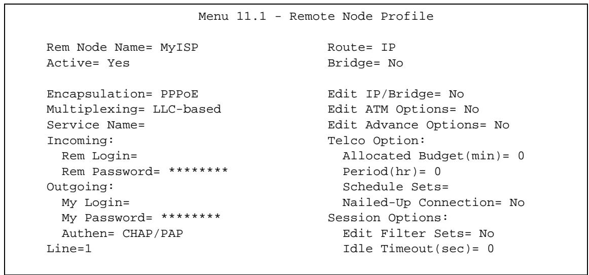
Figure 150 Menu 11.1: Remote Node Profile (nodes 1-7)
The following table describes the labels in this menu.
Table 117 Menu 11.1: Remote Node Profile (nodes 1-7)
| FIELD | DESCRIPTION |
| Rem Node Name | Enter the name of the ISP. |
| Active | Select whether or not you want to use this Internet connection. |
| Encapsulation | Select the type of encapsulation your ISP uses. |
| Multiplexing | Select the method of multiplexing used by your ISP from the drop-down list. Choices are VC or LLC. |
| Service Name | (PPPoE only) Enter the service name provided by your ISP. Leave this field blank if your ISP did not provide one. |
| Incoming | This section is only enabled for PPPoA or PPPoE connections. |
| Rem Login | Type the login name that this remote node will use to call your P-793H v2. The login name and the Rem Password will be used to authenticate this node. |
| Rem Password | Type the password used when this remote node calls your P-793H v2. |
| Outgoing | This section is only enabled for PPPoA or PPPoE connections. |
| My Login | Enter the user name provided by your ISP. |
| My Password | Enter the password provided by your ISP. |
| Retype to Confirm | Enter the password again. |
| Authen | This field appears if you select PPPoE in the Encapsulation field. Select what type of authentication your ISP uses. Select CHAP/PAP if you want the P-793H v2 to support both choices. |
| Line | Select the DSL connection you want the ZyXEL Device to use for outgoing traffic. |
| Route | Press [SPACE BAR] and then [ENTER] to select IP to enable IP-based routing to this remote node. This is not effective unless you enable IP-based routing in the P-793H v2 too. See Menu 1: General Setup in Section 24.1 on page 307.You should enable Route IP, Bridge, or both in this screen. If you disable Route IP and Bridge, the device does not send traffic between the LAN ports and remote node. |
| Bridge | If Route is IP, select Yes in this field to enable bridging to this remote node for protocols that are not supported by IP-based routing (for example, SNA).If Route is None, select Yes in this field to enable bridging to this remote node for all protocols.In either case, this setting is not effective unless you enable bridging in the P-793H v2 too. See Menu 1: General Setup in Section 24.1 on page 307.You should enable Route IP, Bridge, or both in this screen. If you disable Route IP and Bridge, the device does not send traffic between the LAN ports and remote node. |
| Edit IP/Bridge | This field is enabled if Route is IP. If you want to set up the WAN IP address and advanced features for the WAN port, press [SPACE BAR] to select Yes and press [ENTER]. Menu 11.3 appears. |
| Edit ATM Options | This field is enabled if Route is IP. Press [SPACE BAR] to select Yes and press [ENTER] to edit the virtual channel and ATM QoS settings. Menu 11.6 appears. |
| Edit Advance Options | This field is displayed if you are editing remote node 1, and it is only enabled for PPPoE connections. If you want to set up advanced features for the Internet connection, press [SPACE BAR] to select Yes and press [ENTER]. Menu 11.8 appears. |
| Telco Option | This section is only enabled for PPPoA or PPPoE connections. |
| Allocated Budget(min) | Enter the maximum amount of time (in minutes) each call can last.Enter 0 if there is no limit. With Period, you can set a limit on the total outgoing call time of the P-793H v2 within a certain period of time. When the total outgoing call time exceeds the limit, the current call will be dropped and any future outgoing calls will be blocked. |
| Period(hr) | Enter how often (in hours) the Allocated Budget is reset. For example, if you can call for thirty minutes every hour, set the Allocated Budget to 30, and set this field to 1. |
| Schedule Sets | Enter the schedule sets that apply to this connection. |
| Nailed-Up Connection | Select this if you want the P-793H v2 to automatically connect to your ISP when it is turned on and to remain connected all the time.This is not recommended if you pay for your Internet connected based on the amount of time you are connected. |
| Session Options | |
| Edit Filter Sets | If you want to specify input and output filter sets for the WAN port, press [SPACE BAR] to select Yes and press [ENTER]. Menu 11.5 appears. |
| Idle Timeout(sec) | Enter the number of seconds the P-793H v2 should wait while there is no Internet traffic before it automatically disconnects from the ISP. Enter a time interval between 10 and 9999 seconds. |
28.4 Remote Node Network Layer Options
Move the cursor to the Edit IP/Bridge field in menu 11.1, then press [SPACE BAR] to select Yes. Press [ENTER] to open Menu 11.3 - Remote Node Network Layer Options.
Figure 151 Menu 11.3: Remote Node Network Layer Options
Menu 11.3 - Remote Node Network Layer Options
IP Options: Bridge Options:
IP Address Assignment = Static Ethernet Addr Timeout(min) = N/A
Rem IP Addr = 0.0.0.0
Rem Subnet Mask = 0.0.0.0
My WAN Addr = 0.0.0.0
NAT = SUA Only
Address Mapping Set = N/A
Metric = 2
Private = No
RIP Direction = Both
Version = RIP-2B
Multicast = None
IP Policies =
The following table describes the fields in this menu.
Table 118 Menu 11.3: Remote Node Network Layer Options
| FIELD | DESCRIPTION |
| IP Address Assignment | Select Dynamic if your ISP did not give you a fixed (static) IP address. Select Static if your ISP gave you a fixed (static) IP address. The next three fields are not available if you select Dynamic. |
| Rem IP Addr | Enter the IP address of the remote (peer) computer to which the P-793H v2 connects. |
| Rem Subnet Mask | Enter the subnet mask of the remote (peer) computer to which the P-793H v2 connects. |
| My WAN Addr | Enter the fixed (static) IP address provided by your ISP. |
| NAT | Select None if you do not want to use port forwarding, trigger ports, or NAT. |
| Select SUA Only if you want to use one or more of these features and have only one WAN IP address for your P-793H v2. | |
| Select Full Feature if you want to use one or more of these features and have more than one public WAN IP address for your P-793H v2. | |
| Address Mapping Set | This field is enabled if NAT is Full Feature. Specify which address mapping set you want to use for this remote node. |
| Metric | This field sets this route's priority among the routes the P-793H v2 uses.The metric represents the "cost of transmission". A router determines the best route for transmission by choosing a path with the lowest "cost". RIP routing uses hop count as the measurement of cost, with a minimum of "1" for directly connected networks. The number must be between "1" and "15"; a number greater than "15" means the link is down. The smaller the number, the lower the "cost". |
| Private | This field is related to RIP. This field determines whether or not the P-793H v2 includes the route to this remote node in its RIP broadcasts. If you select Yes, this route is not included in RIP broadcast. If you select No, the route to this remote node is propagated to other hosts through RIP broadcasts. Usually, you should keep the default value. |
| RIP Direction | Use this field to control how much routing information the P-793H v2 sends and receives through this connection.None - The P-793H v2 does not send or receive routing information through this connection.Both - The P-793H v2 sends and receives routing information through this connection.In Only - The P-793H v2 only receives routing information through this connection.Out Only - The P-793H v2 only sends routing information through this connection. |
| Version | Select which version of RIP the P-793H v2 uses when it sends or receives information on the subnet.RIP-1 - The P-793H v2 uses RIPv1 to exchange routing information.RIP-2B - The P-793H v2 broadcasts RIPv2 to exchange routing information.RIP-2M - The P-793H v2 multicasts RIPv2 to exchange routing information. |
| Multicast | You do not have to enable multicasting to use RIP-2M. (See RIP Version.)Select which version of IGMP the P-793H v2 uses to support multicasting on this port. Multicasting only sends packets to some computers and is an alternative to unicast (sending packets to one computer) and broadcasting (sending packets to every computer).None - The P-793H v2 does not support multicasting.IGMP-v1 - The P-793H v2 supports IGMP version 1.IGMP-v2 - The P-793H v2 supports IGMP version 2.Multicasting can improve overall network performance. However, it requires extra processing and generates more network traffic. In addition, other computers have to support the same version of IGMP. |
| IP Policies | You can apply up to four policy routes for this remote nodeConfigure the policy routes in menu 25 first. See Chapter 37 on page 411 for information about policy routes. |
| Bridge Options | |
| Ethernet Addr Timeout(min) | This field is enabled if Bridge is Yes in SMT Menu 11.1: Remote Node Profile (nodes 1-7). Type the time (in minutes) for the P-793H v2 to retain the Ethernet address information in its internal tables while the line is down. If this information is retained, your P-793H v2 will not have to recompile the tables when the line comes back up. |
| Once you have completed filling in this menu, press [ENTER] at the message “Press ENTER to Confirm...” to save your configuration and return to menu 11.1, or press [ESC] at any time to cancel. | |
28.5 Remote Node Filter
Move the cursor to the field Edit Filter Sets in menu 11.1, and then press [SPACE BAR] to set the value to Yes. Press [ENTER] to open Menu 11.1.5 - Remote Node Filter.
Use this menu to specify the filter set(s) to apply to the incoming and outgoing traffic between this remote node and the P-793H v2 to prevent certain packets from triggering calls. You can specify up to 4 filter sets separated by commas, for example, 1, 5, 9, 12, in each filter field. Note that spaces are accepted in this field. For more information on defining the filters, please refer to Chapter 32 on
page 357. For PPPoE or PPTP encapsulation, you have the additional option of specifying remote node call filter sets.
Figure 152 Menu 11.5: Remote Node Filter
Menu 11.5 - Remote Node Filter
Input Filter Sets:
    protocol filters=
    device filters=
Output Filter Sets:
    protocol filters=
    device filters=
The following table describes the labels in this menu.
Table 119 Menu 11.5: Remote Node Filter
| FIELD | DESCRIPTION |
| Input Filter Sets | |
| protocol filters | Enter up to four filter sets. If you enter more than one, separate each one with a comma ( , ). |
| device filters | Enter up to four filter sets. If you enter more than one, separate each one with a comma ( , ). |
| Output Filter Sets | |
| protocol filters | Enter up to four filter sets. If you enter more than one, separate each one with a comma ( , ). |
| device filters | Enter up to four filter sets. If you enter more than one, separate each one with a comma ( , ). |
28.6 Remote Node ATM Layer Options
Move the cursor to the Edit ATM Options field in menu 11.1, then press [SPACE BAR] to select Yes. Press [ENTER] to open this menu. This menu depends on the multiplexing and encapsulation you select in menu 11.1.
Figure 153 Menu 11.6: Remote Node ATM Layer Options
Menu 11.6 - Remote Node ATM Layer Options
VPI/VCI (LLC-Multiplexing or PPP-Encapsulation)
VPI # = 0 VCI # = 38 ATM QoS Type= UBR
Peak Cell Rate (PCR)= 0
Sustain Cell Rate (SCR)= 0
Maximum Burst Size (MBS)= 0
The following table describes the fields in this menu.
Table 120 Menu 11.6: Remote Node ATM Layer Options
| FIELD | DESCRIPTION |
| VPI | The valid range for the VPI is 0 to 255. Enter the VPI assigned to you. |
| VCI | The valid range for the VCI is 32 to 65535 (0 to 31 is reserved for local management of ATM traffic). Enter the VCI assigned to you. |
| ATM QoS Type | Select CBR (Constant Bit Rate) to specify fixed (always-on) bandwidth for voice or data traffic. Select UBR (Unspecified Bit Rate) for applications that are non-time sensitive, such as e-mail. Select VBR (Variable Bit Rate) for bursty traffic and bandwidth sharing with other applications. |
| Peak Cell Rate (PCR) | Divide the DSL line rate (bps) by 424 (the size of an ATM cell) to find the Peak Cell Rate (PCR). This is the maximum rate at which the sender can send cells. Type the PCR here. |
| Sustain Cell Rate (SCR) | The Sustain Cell Rate (SCR) sets the average cell rate (long-term) that can be transmitted. Type the SCR, which must be less than the PCR. Note that system default is 0 cells/sec. |
| Maximum Burst Size (MBS) | Maximum Burst Size (MBS) refers to the maximum number of cells that can be sent at the peak rate. Type the MBS, which is less than 65535. |
| Once you have completed filling in this menu, press [ENTER] at the message “Press ENTER to Confirm...” to save your configuration and return to menu 11.1, or press [ESC] at any time to cancel. | |
28.7 Advance Setup Options
You can edit advanced setup options when the encapsulation is PPPoE. Move the cursor to the Edit Advance Options field in menu 11.1 (only for remote node 1), then press [SPACE BAR] to select Yes. Press [ENTER] to open Menu 11.8 - Advanced Setup Options.
Figure 154 Menu 11.8: Advance Setup Options
Menu 11.8 - Advance Setup Options
PPPoE pass-through= No
The following table describes the fields in this menu.
Table 121 Menu 11.8: Advance Setup Options
| FIELD | DESCRIPTION |
| PPPoE pass-through | In addition to the ZyXEL Device's built-in PPPoE client, you can enable PPPoE Passthrough to allow up to ten hosts on the LAN to use PPPoE client software on their computers to connect to the ISP via the ZyXEL Device. Each host can have a separate account and a public WAN IP address.PPPoE pass through is an alternative to NAT for applications where NAT is not appropriate.Disable PPPoE passthrough if you do not need to allow hosts on the LAN to use PPPoE client software on their computers to connect to the ISP. |
| Once you have completed filling in this menu, press [ENTER] at the message “Press ENTER to Confirm...” to save your configuration and return to menu 11.1, or press [ESC] at any time to cancel. | |
Static Route Setup
Use this menu to configure IP and bridge (MAC) static routes.
29.1 IP Static Route Setup
Enter 1 from the menu 12. Select one of the IP static routes as shown next to configure IP static routes in menu 12.1.
Figure 155 Menu 12.1: IP Static Route Setup
Menu 12.1 - IP Static Route Setup
- 16.
Now, enter the index number of the static route that you want to configure.
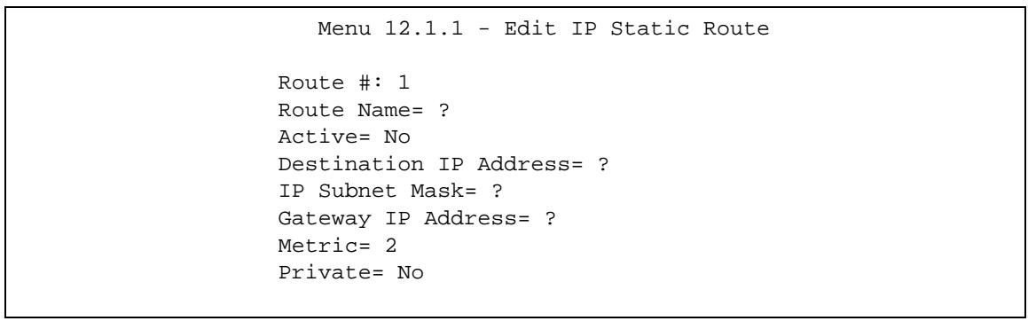
Figure 156 Menu 12.1.1: Edit IP Static Route
The following table describes the fields in this screen.
Table 122 Menu 12.1.1: Edit IP Static Route
| FIELD | DESCRIPTION |
| Route # | This is the index number of the static route that you chose in menu 12. |
| Route Name | Enter a descriptive name for this route. This is for identification purposes only. |
| Active | This field allows you to activate/deactivate this static route. |
| Destination IP Address | This parameter specifies the IP network address of the final destination. Routing is always based on network number. If you need to specify a route to a single host, use a subnet mask of 255.255.255.255 in the subnet mask field to force the network number to be identical to the host ID. |
| IP Subnet Mask | Enter the IP subnet mask for this destination. |
| Gateway IP Address | Enter the IP address of the gateway. The gateway is an immediate neighbor of your P-793H v2 that will forward the packet to the destination. On the LAN, the gateway must be a router on the same segment as your P-793H v2; over the WAN, the gateway must be the IP address of one of the remote nodes. |
| Metric | Enter a number from 1 to 15 to set this route's priority among the P-793H v2's routes (see Section 6.6 on page 96). The smaller the number, the higher priority the route has. |
| Private | This parameter determines if the P-793H v2 will include the route to this remote node in its RIP broadcasts. If set to Yes, this route is kept private and not included in RIP broadcast. If No, the route to this remote node will be propagated to other hosts through RIP broadcasts. |
| Once you have completed filling in this menu, press [ENTER] at the message “Press ENTER to Confirm...” to save your configuration, or press [ESC] to cancel. | |
29.2 Bridge Static Route Setup
Enter 3 from menu 12. Select one of the bridge static routes as shown next to configure IP static routes in menu 12.3.

Figure 157 Menu 12.3: Bridge Static Route Setup
Now, enter the index number of the static route that you want to configure.

Figure 158 Menu 12.3.1: Edit Bridge Static Route
The following table describes the fields in this screen.
Table 123 Menu 12.3.1: Edit Bridge Static Route
| FIELD | DESCRIPTION |
| Route # | This is the index number of the static route that you chose in menu 12. |
| Route Name | Enter a descriptive name for this route. This is for identification purposes only. |
| Active | This field allows you to activate/deactivate this static route. |
| Ether Address | This parameter specifies the MAC address of the final destination. |
| IP Address | Enter the IP address of the gateway. The gateway is an immediate neighbor of your P-793H v2 that will forward the packet to the destination. On the LAN, the gateway must be a router on the same segment as your P-793H v2; over the WAN, the gateway must be the IP address of one of the remote nodes. |
| Gateway Node | Press [SPACE BAR] and then [ENTER] to select the number of the remote node that is the gateway for this static route. |
| Once you have completed filling in this menu, press [ENTER] at the message “Press ENTER to Confirm...” to save your configuration, or press [ESC] to cancel. | |
Use this menu to configure Network Address Translation (NAT) on the P-793H v2.
30.1 Using NAT
Note: You must create a firewall rule in addition to setting up SUA/NAT, to allow traffic from the WAN to be forwarded through the P-793H v2.
30.1.1 SUA (Single User Account) Versus NAT
SUA (Single User Account) is a ZyNOS implementation of a subset of NAT that supports two types of mapping, Many-to-One and Server. See Section 30.2.1 on page 342 for a detailed description of the NAT set for SUA. The P-793H v2 also supports Full Feature NAT to map multiple global IP addresses to multiple private LAN IP addresses of clients or servers using mapping types.
Choose SUA Only if you have just one public WAN IP address for your P-793H v2.
Note: Choose Full Feature if you have multiple public WAN IP addresses for your P-793H v2.
30.1.2 Applying NAT
You apply NAT via menus 4 or 11.3 as displayed next. The next figure shows you how to apply NAT for Internet access in menu 4. Enter 4 from the main menu to go to Menu 4 - Internet Access Setup.
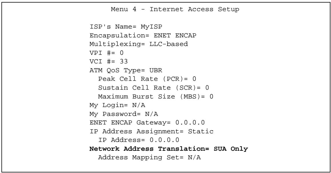
Figure 159 Menu 4: Applying NAT for Internet Access
The following figure shows how you apply NAT to the remote node in menu 11.3.
1 Enter 11 from the main menu.
2 Enter 1 to open Menu 11.1 - Remote Node Profile.
3 Move the cursor to the Edit IP/Bridge field, press [SPACE BAR] to select Yes and then press [ENTER] to bring up Menu 11.3 - Remote Node Network Layer Options.
Figure 160 Menu 11.3: Applying NAT to the Remote Node
Menu 11.3 - Remote Node Network Layer Options
IP Options: Bridge Options:
IP Address Assignment = Static Ethernet Addr Timeout(min) = N/A
Rem IP Addr = 0.0.0.0
Rem Subnet Mask = 0.0.0.0
My WAN Addr = 0.0.0.0
NAT = SUA Only
Address Mapping Set = N/A
Metric = 2
Private = No
RIP Direction = Both
Version = RIP-2B
Multicast = None
IP Policies =
The following table describes the fields in this menu.
Table 124 Applying NAT in Menus 4 & 11.3
| FIELD | DESCRIPTION | OPTIONS |
| Network Address Translation | When you select this option the SMT will use the specified address mapping set (menu 15.1 - see Section 30.2.1 on page 342 for further discussion). You can configure any of the mapping types described in Chapter 8 on page 117. Choose Full Feature if you have multiple public WAN IP addresses for your P-793H v2. When you select Full Feature you must configure at least one address mapping set. | Full Feature |
| NAT is disabled when you select this option. | None | |
| When you select this option the SMT will use Address Mapping Set 255 (menu 15.1 - see Section 30.2.1 on page 342). Choose SUA Only if you have just one public WAN IP address for your P-793H v2. | SUA Only |
30.2 NAT Setup
Use the address mapping sets menus and submenus to create the mapping table used to assign global addresses to computers on the LAN and the DMZ. Set 255 is used for SUA. When you select Full Feature in menu 4 or menu 11.3, the SMT will use the address mapping set that you specify. When you select SUA Only, the SMT will use the pre-configured Set 255 (read only).
A server set is a list of LAN servers mapped to external ports. To use this set, a server rule must be set up inside the NAT address mapping set. Please see the section on port forwarding in Section 8.3 on page 120 for further information on these menus. To configure NAT, enter 15 from the main menu to bring up the following screen.
Figure 161 Menu 15: NAT Setup
Menu 15 - NAT Setup
- Address Mapping Sets
- NAT Server Sets
30.2.1 Address Mapping Sets
Enter 1 to bring up Menu 15.1.1 - Address Mapping Sets.
Figure 162 Menu 15.1: Address Mapping Sets
Menu 15.1 - Address Mapping Sets
1. ACL Default Set
2.
3.
4.
5.
6.
7.
8.
255. SUA (read only)
Select the address mapping set you want to modify. The fields in address 255 are used for SUA and are read-only.
30.2.1.1 User-Defined Address Mapping Sets
Note: The entire set will be deleted if you leave the Set Name field blank and press [ENTER] at the bottom of the screen.
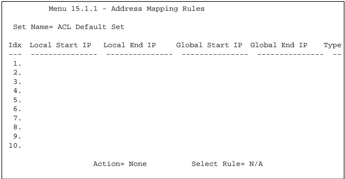
Figure 163 Menu 15.1.1: Address Mapping Rules
Note: The Type, Local and Global Start/End IPs are configured in menu 15.1.1.1 (described later) and the values are displayed here.
Table 125 Menu 15.1.1: Address Mapping Rules
| FIELD | DESCRIPTION |
| Set Name | This is the name of the set you selected in menu 15.1 or enter the name of a new set you want to create. |
| Idx | This is the index or rule number. |
| Local Start IP | Local Start IP is the starting local IP address (ILA). |
| Local End IP | Local End IP is the ending local IP address (ILA). If the rule is for all local IPs, then the start IP is 0.0.0.0 and the end IP is 255.255.255.255. |
| Global Start IP | This is the starting global IP address (IGA). If you have a dynamic IP, enter 0.0.0.0 as the Global Start IP. |
| Global End IP | This is the ending global IP address (IGA). |
| Type | These are the mapping types discussed above. Server allows us to specify multiple servers of different types behind NAT to this machine. See later for some examples. |
| Once you have finished configuring a rule in this menu, press [ENTER] at the message “Press ENTER to Confirm...” to save your configuration, or press [ESC] to cancel. | |
Ordering your rules is important because the P-793H v2 applies the rules in the order that you specify. When a rule matches the current packet, the P-793H v2 takes the corresponding action and the remaining rules are ignored. If there are any empty rules before your new configured rule, your configured rule will be pushed up by that number of empty rules. For example, if you have already configured rules 1 to 6 in your current set and now you configure rule number 9. In the set summary screen, the new rule will be rule 7, not 9.
Now if you delete rule 4, rules 5 to 7 will be pushed up by 1 rule, so as old rule 5 becomes rule 4, old rule 6 becomes rule 5 and old rule 7 becomes rule 6.
Note: You must press [ENTER] at the bottom of the screen to save the whole set. You must do this again if you make any changes to the set – including deleting a rule. No changes to the set take place until this action is taken.
Selecting Edit in the Action field and then selecting a rule brings up the following menu, Menu 15.1.1.1 - Address Mapping Rule in which you can edit an individual rule and configure the Type, Local and Global Start/End IPs.
Note: An IP End address must be numerically greater than its corresponding IP Start address.
Figure 164 Menu 15.1.1.1: Address Mapping Rule
Menu 15.1.1.1 Address Mapping Rule
Type= Server
Local IP:
    Start= N/A
    End = N/A
Global IP:
    Start= 0.0.0.0
    End = N/A
Server Mapping Set= 2
The following table describes the fields in this menu.
Table 126 Menu 15.1.1.1: Address Mapping Rule
| FIELD | DESCRIPTION |
| Type | Press [SPACE BAR] and then [ENTER] to select from a total of five types. These are the mapping types discussed in Chapter 8 on page 117. Server allows you to specify multiple servers of different types behind NAT to this computer. See Section 30.4.3 on page 348 for an example. |
| Local IP | These fields are enabled depending on the Type. |
| Start | Enter the starting local IP address (ILA). |
| End | Enter the ending local IP address (ILA). If the rule is for all local IPs, then put the Start IP as 0.0.0.0 and the End IP as 255.255.255.255. This field is N/A for One-to-One and Server types. |
| Global IP | These fields are enabled depending on the Type. |
| Start | Enter the starting global IP address (IGA). If you have a dynamic IP, enter 0.0.0.0 as the Global IP Start. Note that Global IP Start can be set to 0.0.0.0 only if the types are Many-to-One or Server. |
| End | Enter the ending global IP address (IGA). This field is N/A for One-to-One, Many-to-One and Server types. |
| Server Mapping Set | This field is available only when you select Server in the Type field. Select which server mapping set to use for this rule. |
| Once you have finished configuring a rule in this menu, press [ENTER] at the message "Press ENTER to Confirm..." to save your configuration, or press [ESC] to cancel. | |
30.3 Configuring a Server behind NAT
Note: If you do not assign a Default Server IP address, the P-793H v2 discards all packets received for ports that are not specified here or in the remote management setup.
Follow these steps to configure a server behind NAT:
1 Enter 15 in the main menu to go to Menu 15 - NAT Setup.
2 Enter 2 to open menu 15.2 (and configure the address mapping rules for the WAN port on a P-793H v2 with a single WAN port).
Figure 165 Menu 15.2: NAT Server Sets
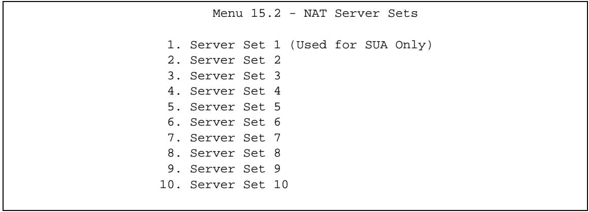
3 Enter 1 to configure the server set used by SUA, or enter the number of the server set you want to modify for full-feature NAT. In Menu 15.2 - NAT Server Setup, configure the port forwarding rules.
Figure 166 Menu 15.2: NAT Server Setup
Menu 15.2 - NAT Server Setup
Rule Start Port No. End Port No. IP Address
| 1. | Default | Default | 0.0.0.0 |
| 2. | 80 | 80 | 192.168.1.10 |
| 3. | 0 | 0 | 0.0.0.0 |
| 4. | 0 | 0 | 0.0.0.0 |
| 5. | 0 | 0 | 0.0.0.0 |
| 6. | 0 | 0 | 0.0.0.0 |
| 7. | 0 | 0 | 0.0.0.0 |
| 8. | 0 | 0 | 0.0.0.0 |
| 9. | 0 | 0 | 0.0.0.0 |
| 10. | 0 | 0 | 0.0.0.0 |
| 11. | 0 | 0 | 0.0.0.0 |
| 12. | 0 | 0 | 0.0.0.0 |
The first entry is for the Default Server. The following table describes the labels in this menu.
Table 127 Menu 15.2: NAT Server Setup
| FIELD | DESCRIPTION |
| Rule | This field is a sequential value, and it is not associated with a specific rule. The sequence is important, however. The P-793H v2 checks each active rule in order, and it only follows the first one that applies. |
| Start Port | This field displays the beginning of the range of port numbers forwarded by this rule. |
| End Port | This field displays the end of the range of port numbers forwarded by this rule. If it is the same as the Start Port, only one port number is forwarded. |
| IP Address | This field displays the IP address of the server to which packet for the selected port(s) are forwarded. |
30.4 General NAT Examples
The following are some examples of NAT configuration.
30.4.1 Internet Access Only
In the following Internet access example, you only need one rule where all your ILAs (Inside Local addresses) map to one dynamic IGA (Inside Global Address) assigned by your ISP.

Figure 167 NAT Example 1
Figure 168 Menu 4: Internet Access & NAT Example
Menu 4 - Internet Access Setup
ISP's Name= MyISP
Encapsulation= ENET ENCAP
Multiplexing= LLC-based
VPI#=0
VCI#=33
ATM QoS Type= UBR
Peak Cell Rate (PCR)=0
Sustain Cell Rate (SCR)=0
Maximum Burst Size (MBS)=0
My Login=N/A
My Password=N/A
ENET ENCAP Gateway=0.0.0.0
IP Address Assignment=Static
IP Address=0.0.0.0
Network Address Translation= SUA Only
Address Mapping Set=N/A
From menu 4 shown above, simply choose the SUA Only option from the Network Address Translation field. This is the Many-to-One mapping discussed in Section 30.4 on page 346. The SUA Only read-only option from the Network Address Translation field in menus 4 and 11.3 is specifically pre-configured to handle this case.
30.4.2 Example 2: Internet Access with a Default Server
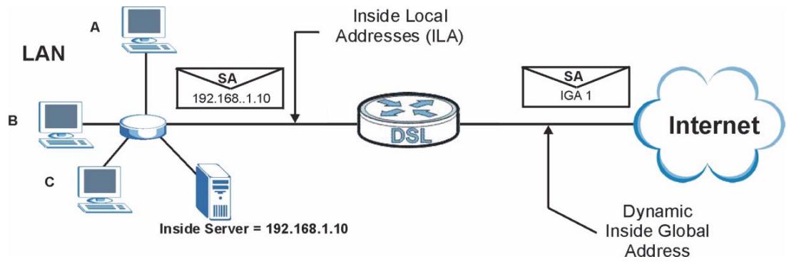
Figure 169 NAT Example 2
In this case, you do exactly as above (use the convenient pre-configured SUA Only set) and also go to menu 15.2.1 to specify the Default Server behind the NAT as shown in the next figure.
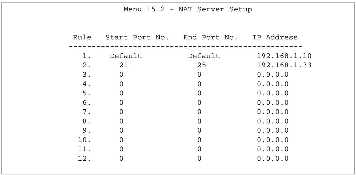
Figure 170 Menu 15.2: Specifying an Inside Server
30.4.3 Example 3: Multiple Public IP Addresses With Inside Servers
In this example, there are 3 IGAs from our ISP. There are many departments but two have their own FTP server. All departments share the same router. The example will reserve one IGA for each department with an FTP server and all departments use the other IGA. Map the FTP servers to the first two IGAs and the other LAN traffic to the remaining IGA. Map the third IGA to an inside web server and mail server. Four rules need to be configured, two bi-directional and two unidirectional as follows.
1 Map the first IGA to the first inside FTP server for FTP traffic in both directions (1: 1 mapping, giving both local and global IP addresses).
2 Map the second IGA to our second inside FTP server for FTP traffic in both directions (1:1 mapping, giving both local and global IP addresses).
3 Map the other outgoing LAN traffic to IGA3 (Many:1 mapping).
4 You also map your third IGA to the web server and mail server on the LAN. Type Server allows you to specify multiple servers, of different types, to other computers behind NAT on the LAN.
The example situation looks somewhat like this:
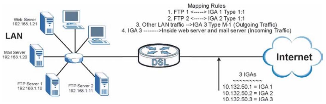
Figure 171 NAT Example 3
1 In this case you need to configure Address Mapping Set 1 from Menu 15.1 - Address Mapping Sets. Therefore you must choose the Full Feature option from the Network Address Translation field (in menu 4 or menu 11.3) in Figure 172 on page 350.
2 Then enter 15 from the main menu.
3 Enter 1 to configure the Address Mapping Sets.
4 Enter 1 to begin configuring this new set. Enter a Set Name, choose the Edit Action and then enter 1 for the Select Rule field. Press [ENTER] to confirm.
5 Select Type as One-to-One (direct mapping for packets going both ways), and enter the local Start IP as 192.168.1.10 (the IP address of FTP Server 1), the global Start IP as 10.132.50.1 (our first IGA). (See Figure 173 on page 351).
6 Repeat the previous step for rules 2 to 4 as outlined above.
7 When finished, menu 15.1.1 should look like as shown in Figure 174 on page 351.
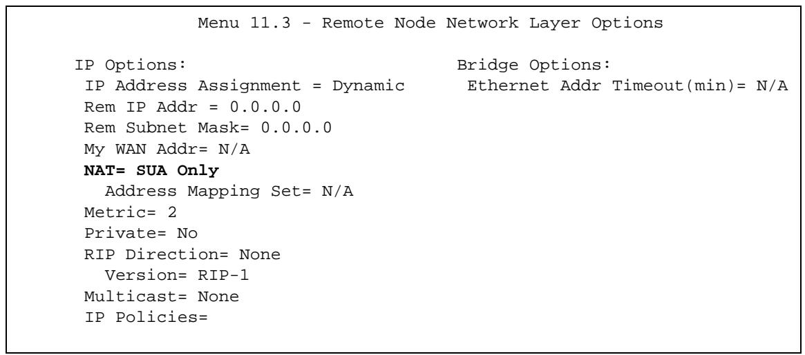
Figure 172 Example 3: Menu 11.3
The following figure shows how to configure the first rule.
Figure 173 Example 3: Menu 15.1.1.1
Menu 15.1.1.1 Address Mapping Rule
Type= One-to-One
Local IP:
    Start= 192.168.1.10
    End = N/A
Global IP:
    Start= 10.132.50.1
    End = N/A
Server Mapping Set= N/A
Figure 174 Example 3: Final Menu 15.1.1
Menu 15.1.1 - Address Mapping Rules
Set Name=Example3
Idx Local Start IP Local End IP Global Start IP Global End IP Type
--- -- -- -- -- -- -- -- -- -- -- -- -- -- -- -- -- -- -- -- -- -- -- -- -- -- -- -- -- -- -- -- -- -- -- -- -- -- -- -- -- -- -- -- -- -- -- -- -- -- -- -- -- -- -- -- -- -- -- -- -- -- -- -- -- -- -- -- -- -- -- -- -- -- -- -- -- -- -- -- -- -- -- -- -- -- -- -- -- -- -- -- -- -- -- -- -- -- -- -- - - - - - - - - - - - - - - - - - - - - - - - - - - - - - - - - - - - - - - - - - - - - - - - - - - - - - - - - - - - - - - - - - - - - - - - - - - - - - - - - - - - - - - - - - - - - - - - - - - - - -
    1. 192.168.1.10 10.132.50.1 1-1
    2. 192.168.1.11 10.132.50.2 1-1
    3. 0.0.0.0 255.255.255.255 10.32.50.3 M-1
    4. 10.132.50.3 Serve+ 5.
    6.
    7.
    8.
    9.
    10.
Action= None Select Rule= N/A
Now configure the IGA3 to map to our web server and mail server on the LAN.
1 Enter 15 from the main menu.
2 Enter 2 to go to menu 15.2.
3 (Enter 1 or 2 from menu 15.2 on a P-793H v2 with multiple WAN ports) configure the menu as shown in Figure 175 on page 352.
Figure 175 Example 3: Menu 15.2
Menu 15.2 - NAT Server Setup
Rule Start Port No. End Port No. IP Address
- Default Default 0.0.0.0
- 80 80 192.168.1.21
- 25 192.168.1.20
- 0 0.0.0.0
- 0 0.0.0.0
- 0 0 0.0.0.0
- 0 0 0.0.0.0
- 0 0.0.0.0
- 0 0.0.0.0
- 0 0.0.0.0
- 0 0.0.0.0
- 0 0.0.0.0
30.4.4 Example 4: NAT Unfriendly Application Programs
Some applications do not support NAT Mapping using TCP or UDP port address translation. In this case it is better to use Many-One-to-One mapping as port numbers do not change for Many-One-to-One (and One-to-One) NAT mapping types. The following figure illustrates this.
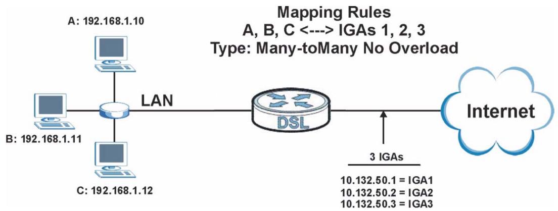
Figure 176 NAT Example 4
Note: Other applications such as some gaming programs are NAT unfriendly because they embed addressing information in the data stream. These applications won't work through NAT even when using One-to-One and Many-One-to-One mapping types.
Follow the steps outlined in example 3 above to configure these two menus as follows.
Figure 177 Example 4: Menu 15.1.1.1: Address Mapping Rule
Menu 15.1.1.1 Address Mapping Rule
Type= Many-to-Many No Overload
Local IP:
    Start= 192.168.1.10
    End = 192.168.1.12
Global IP:
    Start= 10.132.50.1
    End = 10.132.50.3
Server Mapping Set= N/A
After you've configured your rule, you should be able to check the settings in menu 15.1.1 as shown next.Example 4: Menu 15.1.1: Address Mapping Rules
Menu 15.1.1 - Address Mapping Rules
Set Name=Example4
Idx Local Start IP Local End IP Global Start IP Global End IP Type
--- -- 192.168.1.10 192.168.1.12 10.132.50.1 10.132.50.3 M-M N+
2.
3.
4.
5.
6.
7.
8.
9.
10.
Action= None Select Rule= N/A
Use this menu to activate or deactivate the firewall.
31.1 Using P-793H v2 SMT Menus
From the main menu enter 21 to go to Menu 21 - Filter and Firewall Setup to display the screen shown next.
Figure 178 Menu 21: Filter and Firewall Setup
Menu 21 - Filter and Firewall Setup
- Filter Setup
- Firewall Setup
31.1.1 Activating the Firewall
Enter option 2 in this menu to bring up the following screen. Press [SPACE BAR] and then [ENTER] to select Yes in the Active field to activate the firewall. The firewall must be active to protect against Denial of Service (DoS) attacks. Use the web configurator to configure firewall rules. Use the web configurator or SMT
menu 15 to configure the LAN-to-WAN Set Name and WAN-to-LAN Set Name.
Figure 179 Menu 21.2: Firewall Setup
Menu 21.2 - Firewall Setup
The firewall protects against Denial of Service (DoS) attacks when it is active. The default Policy sets
- allow all sessions originating from the LAN to the WAN and
- deny all sessions originating from the WAN to the LAN
You may define additional Policy rules or modify existing ones but please exercise extreme caution in doing so
Active: Yes
LAN-to-WAN Set Name: ACL Default Set
WAN-to-LAN Set Name: ACL Default Set
Please configure the Firewall function through Web Configurator
Note: It is recommended to configure the firewall rules using the web configurator.
Filter Configuration
This chapter shows you how to create and apply filters.
32.1 Introduction to Filters
Your P-793H v2 uses filters to decide whether to allow passage of a data packet and/or to make a call. There are two types of filter applications: data filtering and call filtering. Filters are subdivided into device and protocol filters, which are discussed later.
Data filtering screens the data to determine if the packet should be allowed to pass. Data filters are divided into incoming and outgoing filters, depending on the direction of the packet relative to a port. Data filtering can be applied on either the WAN side or the LAN side. Call filtering is used to determine if a packet should be allowed to trigger a call. Remote node call filtering is only applicable when using PPPoE encapsulation. Outgoing packets must undergo data filtering before they encounter call filtering as shown in the following figure.
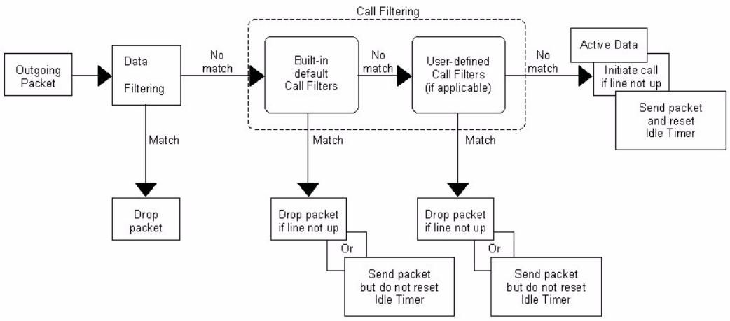
Figure 180 Outgoing Packet Filtering Process
For incoming packets, your P-793H v2 applies data filters only. Packets are processed depending upon whether a match is found. The following sections describe how to configure filter sets.
32.1.1 The Filter Structure of the P-793H v2
A filter set consists of one or more filter rules. Usually, you would group related rules, for example all the rules for NetBIOS, into a single set and give it a descriptive name. The P-793H v2 allows you to configure up to twelve filter sets with six rules in each set, for a total of 72 filter rules in the system. You cannot mix device filter rules and protocol filter rules within the same set. You can apply up to four filter sets to a particular port to block multiple types of packets. With each filter set having up to six rules, you can have a maximum of 24 rules active for a single port.
Sets of factory default filter rules have been configured in menu 21 to prevent NetBIOS traffic from triggering calls and to prevent incoming telnet sessions. A summary of their filter rules is shown in the figures that follow.
The following figure illustrates the logic flow when executing a filter rule. See also Figure 186 on page 365 for the logic flow when executing an IP filter.
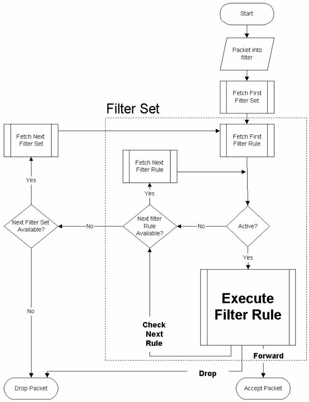
Figure 181 Filter Rule Process
You can apply up to four filter sets to a particular port to block multiple types of packets. With each filter set having up to six rules, you can have a maximum of 24 rules active for a single port.
32.2 Configuring a Filter Set
The P-793H v2 includes filtering for NetBIOS over TCP/IP packets by default. To configure another filter set, follow the procedure below.
1 Enter 21 in the main menu to open menu 21.
Figure 182 Menu 21: Filter and Firewall Setup
Menu 21 - Filter and Firewall Setup
- Filter Setup
- Firewall Setup
2 Enter 1 to bring up the following menu.
Figure 183 Menu 21.1: Filter Set Configuration
Menu 21.1 - Filter Set Configuration
Filter
Set # Comments
1 NetBIOS WAN
2 NetBIOS LAN
3 TELNET WAN
4 PPPoE
5 FTP WAN
6 Enter Filter Set Number to Configure=0
Edit Comments= N/A
3 Select the filter set you wish to configure (1-12) and press [ENTER].
4 Enter a descriptive name or comment in the Edit Comments field and press [ENTER].
5 Press [ENTER] at the message [Press ENTER to confirm] to open Menu 21.1.1 - Filter Rules Summary.
This screen shows the summary of the existing rules in the filter set.
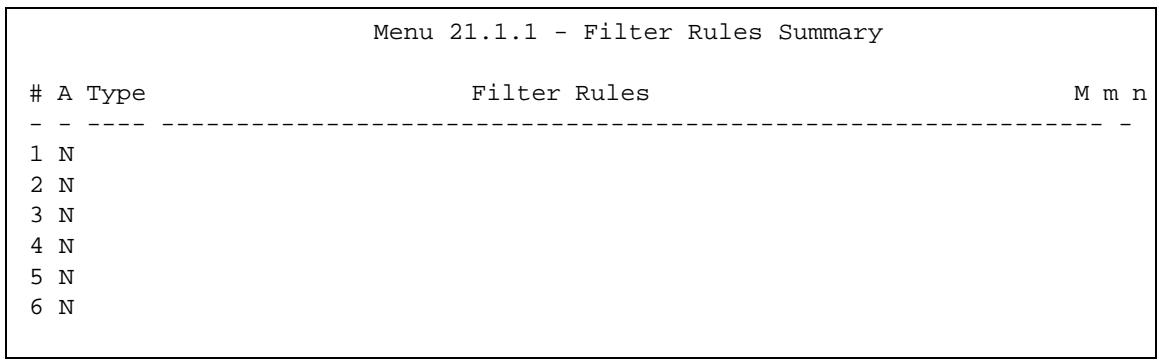
Figure 184 Menu 21.1.1: Filter Rules Summary
The following table describes the labels in this screen.
Table 128 Abbreviations Used in the Filter Rules Summary Menu
| FIELD | DESCRIPTION |
| # | This is an index number. |
| A | Active: "Y" means the rule is active. "N" means the rule is inactive. |
| Type | The type of filter rule: "GEN" for Generic, "IP" for TCP/IP. |
| Filter Rules | These parameters are displayed here. |
| M | More. "Y" means there are more rules to check which form a rule chain with the present rule. An action cannot be taken until the rule chain is complete. "N" means there are no more rules to check. You can specify an action to be taken, in other words forward the packet, drop the packet or check the next rule. For the latter, the next rule is independent of the rule just checked. |
| m | Action Matched. "F" means to forward the packet immediately and skip checking the remaining rules. "D" means to drop the packet. "N" means to check the next rule. |
| n | Action Not Matched. "F" means to forward the packet immediately and skip checking the remaining rules. "D" means to drop the packet. "N" means to check the next rule. |
The following tables contain a brief description of the abbreviations used in the previous menus. The protocol dependent filter rules abbreviation are listed as follows:
Table 129 Rule Abbreviations Used
| ABBREVIATION | DESCRIPTION |
| IP | |
| Pr | Protocol |
| SA | Source Address |
| SP | Source Port number |
| DA | Destination Address |
| DP | Destination Port number |
| GEN | |
| Off | Offset |
| Len | Length |
Refer to the next section for information on configuring the filter rules.
32.2.1 Configuring a Filter Rule
To configure a filter rule, type its number in Menu 21.1.1 - Filter Rules Summary and press [ENTER] to open menu 21.1.1.1 for the rule.
To speed up filtering, all rules in a filter set must be of the same class, that is, protocol filters or generic filters. The class of a filter set is determined by the first rule that you create. When applying the filter sets to a port, separate menu fields are provided for protocol and device filter sets. If you include a protocol filter set in a device filter field or vice versa, the P-793H v2 will warn you and will not allow you to save.
32.2.2 Configuring a TCP/IP Filter Rule
This section shows you how to configure a TCP/IP filter rule. TCP/IP rules allow you to base the rule on the fields in the IP and the upper layer protocol, for example, UDP and TCP headers.
To configure TCP/IP rules, select TCP/IP Filter Rule from the Filter Type field and press [ENTER] to open Menu 21.1.1.1 - TCP/IP Filter Rule, as shown next.
Figure 185 Menu 21.1.1.1: TCP/IP Filter Rule
Menu 21.1.1.1 - TCP/IP Filter Rule
Filter #: 1,1
Filter Type= TCP/IP Filter Rule
Active= No
IP Protocol= 0 IP Source Route= No
Destination: IP Addr=
    IP Mask=
    Port #=
    Port # Comp= None
Source: IP Addr=
    IP Mask=
    Port #=
    Port # Comp= None
TCP Estab= N/A
More= No Log= None
Action Matched= Check Next Rule
Action Not Matched= Check Next Rule
The following table describes how to configure your TCP/IP filter rule.
Table 130 Menu 21.1.1.1: TCP/IP Filter Rule
| FIELD | DESCRIPTION |
| Active | Press [SPACE BAR] and then [ENTER] to select Yes to activate the filter rule or No to deactivate it. |
| IP Protocol | Protocol refers to the upper layer protocol, for example TCP is 6, UDP is 17 and ICMP is 1. Type a value between 0 and 255. A value of 0 matches ANY protocol. |
| IP Source Route | Press [SPACE BAR] and then [ENTER] to select Yes to apply the rule to packets with an IP source route option. Otherwise the packets must not have a source route option. The majority of IP packets do not have source route. |
| Destination | |
| IP Addr | Enter the destination IP Address of the packet you wish to filter. This field is ignored if it is 0.0.0.0. |
| IP Mask | Enter the IP mask to apply to the Destination: IP Addr. |
| Port # | Enter the destination port of the packets that you wish to filter. The range of this field is 0 to 65535. This field is ignored if it is 0. |
| Port # Comp | Press [SPACE BAR] and then [ENTER] to select the comparison to apply to the destination port in the packet against the value given in Destination: Port#.Options are None, Equal, Not Equal, Less and Greater. |
| Source |
Table 130 Menu 21.1.1.1: TCP/IP Filter Rule
| FIELD | DESCRIPTION |
| IP Addr | Enter the source IP Address of the packet you wish to filter. This field is ignored if it is 0.0.0.0. |
| IP Mask | Enter the IP mask to apply to the Source: IP Addr. |
| Port # | Enter the source port of the packets that you wish to filter. The range of this field is 0 to 65535. This field is ignored if it is 0. |
| Port # Comp | Press [SPACE BAR] and then [ENTER] to select the comparison to apply to the source port in the packet against the value given in Source: Port#.Options are None, Equal, Not Equal, Less and Greater. |
| TCP Estab | This field is applicable only when the IP Protocol field is 6, TCP. Press [SPACE BAR] and then [ENTER] to select Yes, to have the rule match packets that want to establish a TCP connection (SYN=1 and ACK=0); if No, it is ignored. |
| More | Press [SPACE BAR] and then [ENTER] to select Yes or No. If Yes, a matching packet is passed to the next filter rule before an action is taken; if No, the packet is disposed of according to the action fields.If More is Yes, then Action Matched and Action Not Matched will be N/A. |
| Log | Press [SPACE BAR] and then [ENTER] to select a logging option from the following:None - No packets will be logged.Action Matched - Only packets that match the rule parameters will be logged.Action Not Matched - Only packets that do not match the rule parameters will be logged.Both - All packets will be logged. |
| ActionMatched | Press [SPACE BAR] and then [ENTER] to select the action for a matching packet OPCs are Check Next Rule, Forward and Drop. |
| Action NotMatched | Press [SPACE BAR] and then [ENTER] to select the action for a packet not matching the rule OPCs are Check Next Rule, Forward and Drop. |
| When you have Menu 21.1.1.1 - TCP/IP Filter Rule configured, press [ENTER] at the message "Press ENTER to Confirm" to save your configuration, or press [ESC] to cancel. This data will now be displayed on Menu 21.1.1 - Filter Rules Summary. | |
The following figure illustrates the logic flow of an IP filter.
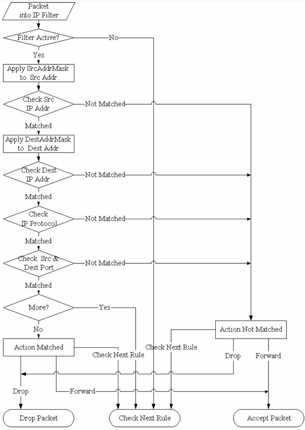
Figure 186 Executing an IP Filter
32.2.3 Configuring a Generic Filter Rule
This section shows you how to configure a generic filter rule. The purpose of generic rules is to allow you to filter non-IP packets. For IP, it is generally easier to use the IP rules directly.
For generic rules, the P-793H v2 treats a packet as a byte stream as opposed to an IP or IPX packet. You specify the portion of the packet to check with the Offset (from 0) and the Length fields, both in bytes. The P-793H v2 applies the Mask (bit-wise ANDing) to the data portion before comparing the result against the Value to determine a match. The Mask and Value are specified in hexadecimal numbers. Note that it takes two hexadecimal digits to represent a byte, so if the length is 4, the value in either field will take 8 digits, for example, FFFFFFFF.
To configure a generic rule, select Generic Filter Rule in the Filter Type field in menu 21.1.1.1 and press [ENTER] to open Generic Filter Rule, as shown below.
Figure 187 Menu 21.1.1.1: Generic Filter Rule
Menu 21.1.1.1 - Generic Filter Rule
Filter #: 1,1
Filter Type= Generic Filter Rule
Active= No
Offset= 0
Length= 0
Mask= N/A
Value= N/A
More= No Log= None
Action Matched= Check Next Rule
Action Not Matched= Check Next Rule
The following table describes the fields in the Generic Filter Rule menu.
Table 131 Menu 21.1.1.1: Generic Filter Rule
| FIELD | DESCRIPTION |
| Filter # | This is the filter set, filter rule co-ordinates, in other words 2,3 refers to the second filter set and the third rule of that set. |
| Filter Type | Use [SPACE BAR] and then [ENTER] to select a rule type. Parameters displayed below each type will be different. TCP/IP filter rules are used to filter IP packets while generic filter rules allow filtering of non-IP packets. Options are Generic Filter Rule and TCP/IP Filter Rule. |
| Active | Select Yes to turn on the filter rule or No to turn it off. |
| Offset | Enter the starting byte of the data portion in the packet that you wish to compare. The range for this field is from 0 to 255. |
| Length | Enter the byte count of the data portion in the packet that you wish to compare. The range for this field is 0 to 8. |
| Mask | Enter the mask (in Hexadecimal notation) to apply to the data portion before comparison. |
| Value | Enter the value (in Hexadecimal notation) to compare with the data portion. |
| More | If Yes, a matching packet is passed to the next filter rule before an action is taken; else the packet is disposed of according to the action fields. If More is Yes, then Action Matched and Action Not Matched will be No. |
| Log | Select the logging option from the following: None - No packets will be logged. Action Matched - Only packets that match the rule parameters will be logged. Action Not Matched - Only packets that do not match the rule parameters will be logged. Both - All packets will be logged. |
| Action Matched | Select the action for a packet matching the rule. Options are Check Next Rule, Forward and Drop. |
| Action Not Matched | Select the action for a packet not matching the rule. Options are Check Next Rule, Forward and Drop. |
| Once you have completed filling in Menu 21.1.1.1 - Generic Filter Rule, press [ENTER] at the message “Press ENTER to Confirm” to save your configuration, or press [ESC] to cancel. This data will now be displayed on Menu 21.1.1 - Filter Rules Summary. | |
32.3 Example Filter
Let's look at an example to block outside users from accessing the P-793H v2 via telnet. Please see our included disk for more example filters.
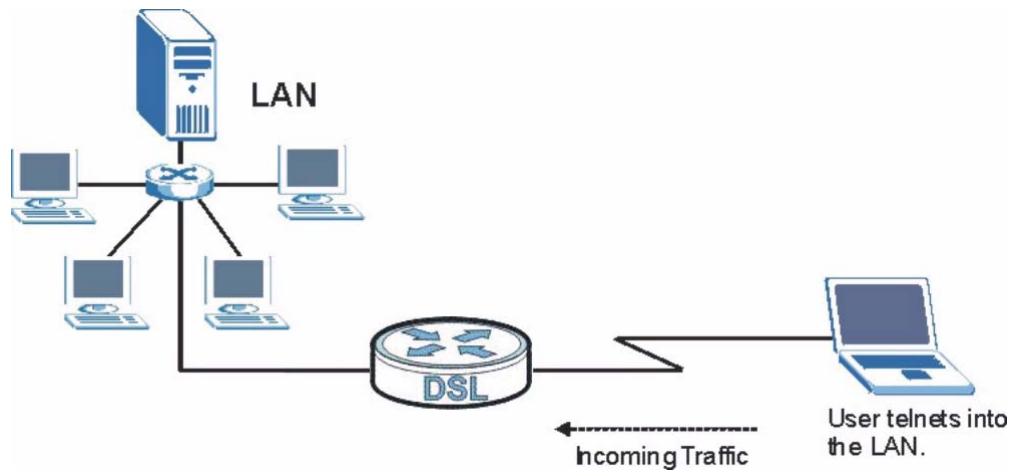
Figure 188 Telnet Filter Example
1 Enter 21 from the main menu to open Menu 21 - Filter and Firewall Setup.
2 Enter 1 to open Menu 21.1 - Filter Set Configuration.
3 Enter the index of the filter set you wish to configure (say 3) and press [ENTER].
4 Enter a descriptive name or comment in the Edit Comments field and press [ENTER].
5 Press [ENTER] at the message [Press ENTER to confirm] to open Menu 21.1.3 - Filter Rules Summary.
6 Enter 1 to configure the first filter rule (the only filter rule of this set). Make the entries in this menu as shown in the following figure.
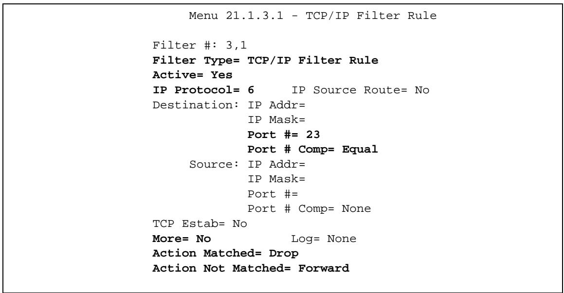
Figure 189 Example Filter: Menu 21.1.3.1
The port number for the telnet service (TCP protocol) is 23. See RFC 1060 for port numbers of well-known services.
When you press [ENTER] to confirm, you will see the following screen. Note that there is only one filter rule in this set.
Figure 190 Example Filter Rules Summary: Menu 21.1.3
Menu 21.1.3 - Filter Rules Summary
<h1 id="a-type-filter-rules-m-m-n">A Type Filter Rules M m n</h1>
- - -
1 Y IP Pr=6, SA=0.0.0.0, DA=0.0.0.0, DP=23 N D F
2 N
3 N
4 N
5 N
6 N
This shows you that you have configured and activated (A = Y) a TCP/IP filter rule (Type = , Pr = 6 ) for destination telnet ports ( DP = 23 ).
M = N means an action can be taken immediately. The action is to drop the packet (m = D) if the action is matched and to forward the packet immediately (n = F) if the action is not matched no matter whether there are more rules to be checked (there aren't in this example).
After you've created the filter set, you must apply it.
1 Enter 11 from the main menu to go to menu 11.
2 Enter 1 or 2 to open Menu 11.x - Remote Node Profile.
3 Go to the Edit Filter Sets field, press [SPACE BAR] to select Yes and press [ENTER].
4 This brings you to menu 11.1.4. Apply a filter set (our example filter set 3) as shown in Figure 152 on page 331.
5 Press [ENTER] to confirm after you enter the set numbers and to leave menu 11.1.4.
32.4 Filter Types and NAT
There are two classes of filter rules, Generic Filter (Device) rules and protocol filter (TCP/IP) rules. Generic filter rules act on the raw data from/to LAN and WAN. Protocol filter rules act on the IP packets. Generic and TCP/IP filter rules are discussed in more detail in the next section. When NAT (Network Address
Translation) is enabled, the inside IP address and port number are replaced on a connection-by-connection basis, which makes it impossible to know the exact address and port on the wire. Therefore, the P-793H v2 applies the protocol filters to the "native" IP address and port number before NAT for outgoing packets and after NAT for incoming packets. On the other hand, the generic, or device filters are applied to the raw packets that appear on the wire. They are applied at the point when the P-793H v2 is receiving and sending the packets; in other words the interface. The interface can be an Ethernet port or any other hardware port. The following diagram illustrates this.
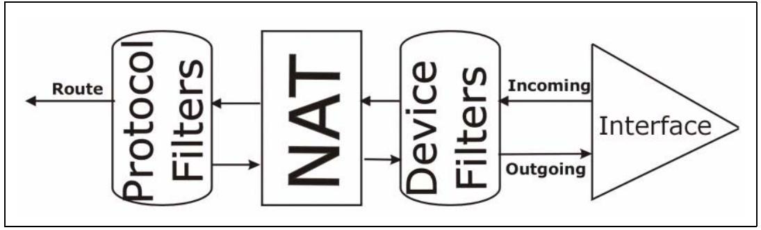
Figure 191 Protocol and Device Filter Sets
32.5 Firewall Versus Filters
Firewall configuration is discussed in Chapter 10 on page 149. Further comparisons are also made between filtering, NAT and the firewall.
32.6 Applying a Filter
This section shows you where to apply the filter(s) after you design it (them). The P-793H v2 already has filters to prevent NetBIOS traffic from triggering calls, and block incoming telnet, FTP and HTTP connections.
Note: If you do not activate the firewall, it is advisable to apply filters.
32.6.1 Applying LAN Filters
LAN traffic filter sets may be useful to block certain packets, reduce traffic and prevent security breaches. Go to menu 3.1 (shown next) and enter the number(s) of the filter set(s) that you want to apply as appropriate. You can choose up to four filter sets (from twelve) by entering their numbers separated by commas, for
example 3, 4, 6, 11. Input filter sets filter incoming traffic to the P-793H v2 and output filter sets filter outgoing traffic from the P-793H v2.
Figure 192 Filtering LAN Traffic
Menu 3.1 - LAN Port Filter Setup
Input Filter Sets:
    protocol filters=
    device filters=
Output Filter Sets:
    protocol filters=
    device filters=
32.6.2 Applying Remote Node Filters
Go to menu 11.5 (shown below – note that call filter sets are only present for PPPoA or PPPoE encapsulation) and enter the number(s) of the filter set(s) as appropriate. You can cascade up to four filter sets by entering their numbers separated by commas. The P-793H v2 already has filters to prevent NetBIOS traffic from triggering calls, and block incoming telnet, FTP and HTTP connections.
Figure 193 Filtering Remote Node Traffic
Menu 11.5 - Remote Node Filter
Input Filter Sets:
    protocol filters=
    device filters=
Output Filter Sets:
    protocol filters=
    device filters=
Call Filter Sets:
    protocol filters=
    device filters=
System Password
Use this menu to change your password. This is the same password used to access the web configurator. To open this menu, enter 23 in the main menu.

Figure 194 Menu 23: System Password
The following table describes the labels in this menu.
Table 132 Menu 23: System Password
| FIELD | DESCRIPTION |
| Old Password | Enter the current administrator password for the P-793H v2. |
| New Password | Enter the new administrator password for the P-793H v2. |
| Retype to confirm | Enter the new administrator password again. |
System Information & Diagnosis
This chapter covers SMT menus 24.1 to 24.4.
34.1 Introduction to System Status
This chapter covers the diagnostic tools that help you to maintain your P-793H v2. These tools include updates on system status, port status and log and trace capabilities.
Select menu 24 in the main menu to open Menu 24 - System Maintenance, as shown below.
Figure 195 Menu 24: System Maintenance
Menu 24 - System Maintenance
- System Status
- System Information and Console Port Speed
- Log and Trace
- Diagnostic
- Backup Configuration
- Restore Configuration
- Upload Firmware
- Command Interpreter Mode
- Call Control
- Time and Date Setting
- Remote Management
34.2 System Status
The first selection, System Status, gives you information on the version of your system firmware and the status4 and statistics of the ports, as shown in the next figure. System Status is a tool that can be used to mon23itor your P-793H v2. Specifically, it gives you information on your system firmware version, number of packets sent and number of packets received.
To get to the System Status:
1 Enter number 24 to go to Menu 24 - System Maintenance.
2 In this menu, enter 1 to open System Maintenance - Status.
3 There are three commands in Menu 24.1 - System Maintenance - Status. Entering 1 drops the WAN connection, 9 resets the counters and [ESC] takes you back to the previous screen.
Figure 196 Menu 24.1: System Maintenance - Status
| Menu 24.1 - System Maintenance - Status 06:28:45 Sat. Jan. 01, 2000 | |||||||
| Node-Lnk Status | TxPkts | RxPkts | Errors | Tx B/s | Rx B/s | Up Time | |
| 1-ENET N/A | 0 | 0 | 0 | 0 | 0 | 0:00:00 | |
| 2 N/A | 0 | 0 | 0 | 0 | 0 | 0:00:00 | |
| 3 N/A | 0 | 0 | 0 | 0 | 0 | 0:00:00 | |
| 4 N/A | 0 | 0 | 0 | 0 | 0 | 0:00:00 | |
| 5 N/A | 0 | 0 | 0 | 0 | 0 | 0:00:00 | |
| 6 N/A | 0 | 0 | 0 | 0 | 0 | 0:00:00 | |
| 7 N/A | 0 | 0 | 0 | 0 | 0 | 0:00:00 | |
| 8 N/A | 0 | 0 | 0 | 0 | 0 | 0:00:00 | |
| My WAN IP (from ISP): 0.0.0.0 | |||||||
| Ethernet: WAN: Status: 100M/Full Duplex TxPkts: 4210 Line Status: Down Collisions: 0 RxPkts: 4466 Transfer Rate: 0 kbps CPU Load = 1.27% Press Command: COMMANDS: 1-Reset Counters ESC-Exit | |||||||
The following table describes the fields present in Menu 24.1 - System Maintenance - Status. These fields are read-only and meant for diagnostic purposes. The upper right corner of the screen shows the time and date.
Table 133 Menu 24.1: System Maintenance - Status
| FIELD | DESCRIPTION |
| Node-Lnk | This field is the remote node index number and link type (encapsulation). |
| Status | This field displays Down (line is down), Up (line is up or connected) if you're using Ethernet encapsulation and Down (line is down), Up (line is up or connected), Idle (line (ppp) idle), Dial (starting to trigger a call) and Drop (dropping a call) if you're using PPPoE encapsulation. It displays N/A if the port is not connected. |
| TxPkts | This is the number of packets transmitted from the P-793H v2 to the remote node. |
| RxPkts | This is the number of packets received by the P-793H v2 from the remote node. |
| Errors | This is the number of error packets on this connection. |
| Tx B/s | This field shows the transmission rate in bytes per second on this port. |
| Rx B/s | This field shows the reception rate in bytes per second on this port. |
| Up Time | This is the total amount of time the this channel has been connected to the remote node. |
| My WAN IP (from ISP) | This is the IP address assigned by your ISP or the static IP address you set up in menu 4. |
| Ethernet: | This section displays information about the LAN ports. |
| Status | This field displays the speed and duplex settings of the LAN ports. |
| Collisions | This is the number of collisions on this port. |
| TxPkts | This is the number of transmitted packets on this port. |
| RxPkts | This is the number of received packets on this port. |
| WAN | This section displays information about the WAN port. Note: In a point-to-2points connection this field only displays line 1 status. |
| Line Status | This field displays the port speed and duplex setting if you're using Ethernet encapsulation and Down (line is down or not connected), Idle (line (ppp) idle), Dial (starting to trigger a call) or Drop (dropping a call) if you're using PPPoE encapsulation. |
| Transfer Rate | This field shows the transmission speed in kilobits per second on this port. |
| CPU Load | This field displays the percentage of CPU utilization. |
| You may enter 1 to reset the counters or [ESC] to return to menu 24. | |
34.3 System Information and Console Port Speed
This section describes your system and allows you to choose different console port speeds. To get to the System Information and Console Port Speed:
1 Enter 24 to go to Menu 24 - System Maintenance.
2 Enter 2 to open Menu 24.2 - System Information and Console Port Speed
3 From this menu you have two choices as shown in the next figure:
Figure 197 Menu 24.2: System Information and Console Port Speed
Menu 24.2 - System Information and Console Port Speed
- System Information
- Console Port Speed
34.3.1 System Information
System Information gives you information about your system as shown below. More specifically, it gives you information on your routing protocol, Ethernet address, IP address, etc.
Figure 198 Menu 24.2.1: System Maintenance - Information
Menu 24.2.1 - System Maintenance - Information
Name: P-793H v2
Routing: IP ZyNOS F/W Version: V3.40(BKT.0)b1_20100115 | 01/15/2010
SHDSL Chipset Vendor: IFX Soc2U 1.1-1.6.0_001
Standard: ETSI(ANNEX_B)
LAN Ethernet Address: 00:13:49:65:43:21 IP Address: 192.168.1.1 IP Mask: 255.255.255.0 DHCP: Server
The following table describes the fields in this screen.
Table 134 Menu 24.2.1: System Maintenance - Information
| FIELD | DESCRIPTION |
| Name | This is the P-793H v2's system name + domain name assigned in menu 1. For example, System Name= xxx; Domain Name= baboo.mickey.com Name= xxx.baboo.mickey.com |
| Routing | Refers to the routing protocol used. |
| ZyNOS F/W Version | Refers to the version of ZyXEL's Network Operating System software. |
| SHDSL Chipset Vendor | Refers to the SHDSL chipset inside the P-793H v2. |
| Standard | This refers to the operational protocol the P-793H v2 and DSLAM (Digital Subscriber Line Access Multiplexer) are using. |
| LAN | |
| Ethernet Address | Refers to the Ethernet MAC (Media Access Control) address of your P-793H v2. |
| IP Address | This is the IP address of the P-793H v2 in dotted decimal notation. |
| IP Mask | This shows the IP mask of the P-793H v2. |
| DHCP | This field shows the DHCP setting of the P-793H v2. |
| When finished viewing, press [ESC] or [ENTER] to exit. | |
34.3.2 Console Port Speed
You can change the speed of the console port through Menu 24.2.2 - System Maintenance - Change Console Port Speed. Your P-793H v2 supports 9600 (default), 19200, 38400, 57600, and 115200 bps for the console port. Press [SPACE BAR] and then [ENTER] to select the desired speed in menu 24.2.2, as shown next.
Figure 199 Menu 24.2.2: System Maintenance: Change Console Port Speed
Menu 24.2.2 - System Maintenance - Change Console Port Speed Console Port Speed: 9600
34.4 Log and Trace
There are two logging facilities in the P-793H v2. The first is the error logs and trace records that are stored locally. The second is the UNIX syslog facility for message logging.
34.4.1 Viewing Error Log
The first place you should look for clues when something goes wrong is the error/trace log. Follow the procedure below to view the local error/trace log:
1 Select option 24 from the main menu to open Menu 24 - System Maintenance.
2 From menu 24, select option 3 to open Menu 24.3 - System Maintenance - Log and Trace.
3 Select the first option from Menu 24.3 - System Maintenance - Log and Trace to display the error log in the system.
After the P-793H v2 finishes displaying, you will have the option to clear the error log.
Figure 200 Menu 24.3: System Maintenance - Log and Trace
Menu 24.3 - System Maintenance - Log and Trace
1. View Error Log
2. UNIX Syslog
Examples of typical error and information messages are presented in the following figure.
Figure 201 Examples of Error and Information Messages
34 Sat Jan 1 00:00:02 2000 PP05 -WARN SNMP TRAP 3: link up
35 Sat Jan 1 00:00:04 2000 PP00 INFO Channel 0 ok
36 Sat Jan 1 00:00:06 2000 PP0c INFO LAN promiscuous mode <0>
37 Sat Jan 1 00:00:06 2000 PP00 -WARN SNMP TRAP 0: cold start
38 Sat Jan 1 00:00:06 2000 PP00 INFO main: init completed
39 Sat Jan 1 00:00:06 2000 PP00 INFO Starting Connectivity Monitor
40 Sat Jan 1 00:00:06 2000 PP18 INFO adjtime task pause 1 day
41 Sat Jan 1 00:00:06 2000 PP19 INFO monitoring WAN connectivity
42 Sat Jan 1 00:00:06 2000 PP06 WARN MPOA Link Down
43 Sat Jan 1 04:10:22 2000 PP0c WARN netMakeChannDial: err=-3001
44 Sat Jan 1 04:10:42 2000 PP10 WARN Last errorlog repeat 18 Times
45 Sat Jan 1 04:10:42 2000 PP10 INFO SMT Password pass
46 Sat Jan 1 04:10:42 2000 PP00 INFO SMT Session Begin
47 Sat Jan 1 04:10:44 2000 PPoC WARN netMakeChannDial: err=-3001
48 Sat Jan 1 04:46:08 2000 PPoC WARN Last errorlog repeat 216 Times
49 Sat Jan 1 04:46:08 2000 PPoC INFO SMT Session End
51 Sat Jan 1 04:46:59 2000 PPoC WARN netMakeChannDial: err=-3001
52 Sat Jan 1 04:58:00 2000 PP1O WARN Last errorlog repeat 65 Times
53 Sat Jan 1 04:58:0O 2OOO PP1O INFO SMT Password pass
Clear Error Log (y/n):
34.4.2 Syslog Logging
The P-793H v2 uses the syslog facility to log the CDR (Call Detail Record) and system messages to a syslog server. Syslog and accounting can be configured in Menu 24.3.2 - System Maintenance - Syslog Logging, as shown next.
Figure 202 Menu 24.3.2: System Maintenance - UNIX Syslog
Menu 24.3.2 - System Maintenance - UNIX Syslog
UNIX Syslog:
Active= No
Syslog IP Address= 0.0.0.0
Log Facility= Local 1
You need to configure the syslog parameters described in the following table to activate syslog then choose what you want to log.
Table 135 Menu 24.3.2: System Maintenance - UNIX Syslog
| FIELD | DESCRIPTION |
| UNIX Syslog: | |
| Active | Press [SPACE BAR] and then [ENTER] to turn syslog on or off. |
| Syslog IP Address | Enter the server name or IP address of the syslog server that will log the selected categories of logs. |
| Log Facility | Press [SPACE BAR] and then [ENTER] to select a location. The log facility allows you to log the messages to different files in the syslog server. Refer to the documentation of your syslog program for more details. |
| When finished configuring this screen, press [ENTER] to confirm or [ESC] to cancel. | |
Your P-793H v2 sends five types of syslog messages. Some examples (not all P-793H v2 specific) of these syslog messages with their message formats are shown next:
1 CDR
| CDR Message Format |
| SdcmdSyslogSend( SYSLOG_CDR, SYSLOG_INFO, String); |
| String = board xx line xx channel xx, call xx, str |
| board = the hardware board ID |
| line = the WAN ID in a board |
| Channel = channel ID within the WAN |
| call = the call reference number which starts from 1 and increments by 1 for each new call |
| str = C01 Outgoing Call dev xx ch xx (dev:device No. ch:channel No.) |
| L02 Tunnel Connected(L2TP) |
| C02 OutCall Connected xxxx (means connected speed) xxxx (means Remote Call Number) |
| L02 Call Terminated |
| C02 Call Terminated |
| Jul 19 11:19:27 192.168.102.2 ZyXEL: board 0 line 0 channel 0, call 1, C01 Outgoing Call dev=2 ch=0 40002 |
| Jul 19 11:19:32 192.168.102.2 ZyXEL: board 0 line 0 channel 0, call 1, C02 OutCall Connected 64000 40002 |
| Jul 19 11:20:06 192.168.102.2 ZyXEL: board 0 line 0 channel 0, call 1, C02 Call Terminated |
2 Packet triggered
| Packet triggered Message Format |
| SdcmdSyslogSend( SYSLOG_PKTRI, SYSLOG_NOTICE, String ); String = Packet trigger: Protocol=xx Data=xxxxxxxxx......x Protocol: (1:IP 2:IPX 3:IPXHC 4:BPDU 5:ATALK 6:IPNG) Data: We will send forty-eight Hex characters to the server |
| Jul 19 11:28:39 192.168.102.2 ZyXEL: Packet Trigger: Protocol=1, Data=4500003c100100001f010004c0a86614ca849a7b08004a5c0200010061626364 65666768696a6b6c6d6e6f7071727374 Jul 19 11:28:56 192.168.102.2 ZyXEL: Packet Trigger: Protocol=1, Data=4500002c1b0140001f06b50ec0a86614ca849a7b0427001700195b3e00000000 600220008cd40000020405b4 Jul 19 11:29:06 192.168.102.2 ZyXEL: Packet Trigger: Protocol=1, Data=45000028240140001f06ac12c0a86614ca849a7b0427001700195b451d143013 5004000077600000 |
3 Filter log
| Filter log Message Format |
| SdcmdSyslogSend(SYSLOG_FILLOG, SYSLOG_NOTICE, String); |
| String = IP[Src=xx.xx.xx.xx Dst=xx.xx.xx.xx prot spi=xxxx dpo=xxxx] S04>R01mD |
| IP[...] is the packet header and S04>R01mD means filter set 4 (S) and rule 1 (R), match (m) drop (D). |
| Src: Source Address |
| Dst: Destination Address |
| prot: Protocol ("TCP","UDP","ICMP") |
| spo: Source port |
| dpo: Destination portMar 03 10:39:43 202.132.155.97 ZyXEL:GEN[FFFFFFnordff0080] }S05>R01mF |
| Mar 03 10:41:29 202.132.155.97 ZyXEL: |
| GEN[00a0c5f502fnord010080] }S05>R01mF |
| Mar 03 10:41:34 202.132.155.97 ZyXEL: |
| IP[Src=192.168.2.33 Dst=202.132.155.93 ICMP]} }S04>R01mF |
| Mar 03 11:59:20 202.132.155.97 ZyXEL: |
| GEN[00a0c5f502fnord010080] }S05>R01mF |
| Mar 03 12:00:52 202.132.155.97 ZyXEL: |
| GEN[FFFFFF0080] }S05>R01mF |
| Mar 03 12:00:57 202.132.155.97 ZyXEL: |
| GEN[00a0c5f502010080] }S05>R01mF |
| Mar 03 12:01:06 202.132.155.97 ZyXEL: |
| IP[Src=192.168.2.33 Dst=202.132.155.93 TCP spi=01170 dpo=00021]} }S04>R01mF |
4 PPP log
| PPP Log Message Format |
| SdcmdSyslogSend( SYSLOG_PPPLOG, SYSLOG_NOTICE, String); |
| String = ppp:Proto Starting / ppp:Proto Opening / ppp:Proto Closing / ppp:Proto Shutdown |
| Proto = LCP / ATCP / BACP / BCP / CBCP / CCP / CHAP/ PAP / IPCP / IPXCP |
| Jul 19 11:42:44 192.168.102.2 ZyXEL: ppp:LCP Closing |
| Jul 19 11:42:49 192.168.102.2 ZyXEL: ppp:IPCP Closing |
| Jul 19 11:42:54 192.168.102.2 ZyXEL: ppp:CCP Closing |
5 Firewall log
| Firewall Log Message Format |
| SdcmdSyslogSend(SYSLOG FIREWALL, SYSLOG_NOTICE, buf); |
| buf = IP[Src=xx.xx.xx.xx :spo=xxxx Dst=xx.xx.xx.xx : dpo=xxxx | prot | rule | action] |
| Src: Source Address |
| spo: Source port (empty means no source port information) |
| Dst: Destination Address |
| dpo: Destination port (empty means no destination port information) |
| prot: Protocol ("TCP","UDP","ICMP","IGMP","GRE","ESP") |
| rule: <a,b> where a means "set" number; b means "rule" number. |
| Action: nothing(N) block (B) forward (F) |
| 08-01-200011:48:41Local1Notice192.168.10.10RAS: FW 172.21.1.80 :137 - >172.21.1.80 :137 |UDP|default permit:<2,0>|B |
| 08-01-200011:48:41Local1Notice192.168.10.10RAS: FW 192.168.77.88 :520 - >192.168.77.88 :520 |UDP|default permit:<2,0>|B |
| 08-01-200011:48:39Local1Notice192.168.10.10RAS: FW 172.21.1.50 - >172.21.1.50 |IGMP<2>|default permit:<2,0>|B |
| 08-01-200011:48:39Local1Notice192.168.10.10RAS: FW 172.21.1.25 - >172.21.1.25 |IGMP<2>|default permit:<2,0>|B |
34.5 Diagnostic
The diagnostic facility allows you to test the different aspects of your P-793H v2 to determine if it is working properly. Menu 24.4 allows you to choose among various
types of diagnostic tests to evaluate your system, as shown next. Not all fields are available on all models.
Follow the procedure below to get to Menu 24.4 - System Maintenance - Diagnostic.
1 From the main menu, select option 24 to open Menu 24 - System Maintenance.
2 From this menu, select option 4. Diagnostic. This will open Menu 24.4 - System Maintenance - Diagnostic.
Figure 203 Menu 24.4: System Maintenance - Diagnostic
Menu 24.4 - System Maintenance - Diagnostic
xDSL System
1. Reset xDSL 21. Reboot System
22. Command Mode
TCP/IP
12. Ping Host
Enter Menu Selection Number:
Host IP Address= N/A
The following table describes the labels in this screen.
Table 136 Menu 24.4: System Maintenance - Diagnostic
| FIELD | DESCRIPTION |
| Reset xDSL | Enter 1 to reset the DSL connection on the WAN port. |
| Ping Host | Enter 12 to ping any machine (with an IP address) on your LAN or WAN. Enter its IP address in the Host IP Address field below. |
| Reboot System | Enter 11 to reboot the P-793H v2. |
| Command Mode | Enter 22 to go to the Command Interpreter (CI) for further diagnosis. You can also enter the CI using menu 24.8. |
| Host IP Address | If you entered 1in the Enter Menu Selection Number field, then enter the IP address of the computer you want to ping in this field. |
| Enter the number of the selection you would like to perform or press [ESC] to cancel. | |
Firmware and Configuration File Maintenance
This chapter tells you how to back up and restore your configuration file as well as upload new firmware and a new configuration file.
35.1 Introduction
Use the instructions in this chapter to change the P-793H v2's configuration file or upgrade its firmware. After you configure your P-793H v2, you can backup the configuration file to a computer. That way if you later misconfigure the P-793H v2, you can upload the backed up configuration file to return to your previous settings. You can alternately upload the factory default configuration file if you want to return the P-793H v2 to the original default settings. The firmware determines the P-793H v2's available features and functionality. You can download new firmware releases from your nearest ZyXEL FTP site to use to upgrade your P-793H v2's performance.
35.2 Filename Conventions
The configuration file (often called the romfile or rom-0) contains the factory default settings in the menus such as password, DHCP Setup, TCP/IP Setup, etc. It arrives from ZyXEL with a "rom" filename extension. Once you have customized the P-793H v2's settings, they can be saved back to your computer under a filename of your choosing.
ZyNOS (ZyXEL Network Operating System sometimes referred to as the "ras" file) is the system firmware and has a "bin" filename extension. With many FTP and TFTP clients, the filenames are similar to those seen next.
ftp> put firmware.bin ras
This is a sample FTP session showing the transfer of the computer file "firmware.bin" to the P-793H v2.
ftp> get rom-0 config.cfg
This is a sample FTP session saving the current configuration to the computer file "config.cfg".
If your (T)FTP client does not allow you to have a destination filename different than the source, you will need to rename them as the P-793H v2 only recognizes "rom-0" and "ras". Be sure you keep unaltered copies of both files for later use.
The following table is a summary. Please note that the internal filename refers to the filename on the P-793H v2 and the external filename refers to the filename not on the P-793H v2, that is, on your computer, local network or FTP site and so the name (but not the extension) may vary. After uploading new firmware, see the ZyNOS F/W Version field in Menu 24.2.1 - System Maintenance -
Information to confirm that you have uploaded the correct firmware version. The AT command is the command you enter after you press "y" when prompted in the SMT menu to go into debug mode.
Table 137 Filename Conventions
| FILE TYPE | INTERNA L NAME | EXTERNAL NAME | DESCRIPTIO N |
| Configuration File | Rom-0 | This is the configuration filename on the P- 793H v2. Uploading the rom-0 file replaces the entire ROM file system, including your P- 793H v2 configurations, system-related data (including the default password), the error log and the trace log. | *.rom |
| Firmware | Ras | This is the generic name for the ZyNOS firmware on the P-793H v2. | *.bin |
35.3 Backup Configuration
Note: The P-793H v2 displays different messages explaining different ways to backup, restore and upload files in menus 24.5, 24.6, 24.7.1 and 24.7.2 depending on whether you use the console port or Telnet.
Option 5 from Menu 24 - System Maintenance allows you to backup the current P-793H v2 configuration to your computer. Backup is highly recommended once your P-793H v2 is functioning properly. FTP is the preferred method for backing up your current configuration to your computer since it is faster. You can also perform backup and restore using menu 24 through the console port. Any serial communications program should work fine; however, you must use Xmodem protocol to perform the download/upload and you don't have to rename the files.
Please note that terms "download" and "upload" are relative to the computer. Download means to transfer from the P-793H v2 to the computer, while upload means from your computer to the P-793H v2.
35.3.1 Backup Configuration
Follow the instructions as shown in the next screen.
Figure 204 Menu 24.5: Backup Configuration
Menu 24.5 - Backup Configuration
To transfer the configuration file to your computer, follow the procedure below:
- Launch the FTP client on your computer.
- Type "open" and the IP address of your system. Then type "root" and SMT password as requested.
- Locate the 'rom-0' file.
- Type 'get rom-0' to back up the current system configuration to your computer.
For details on FTP commands, please consult the documentation of your FTP client program. For details on backup using TFTP (note that you must remain
in this menu to back up using TFTP), please see your user manual.
35.3.2 Using the FTP Command from the Command Line
1 Launch the FTP client on your computer.
2 Enter "open", followed by a space and the IP address of your P-793H v2.
3 Press [ENTER] when prompted for a username.
4 Enter your password as requested (the default is "1234").
5 Enter "bin" to set transfer mode to binary.
6 Use "get" to transfer files from the P-793H v2 to the computer, for example, "get rom-0 config.rom" transfers the configuration file on the P-793H v2 to your computer and renames it "config.rom". See earlier in this chapter for more information on filename conventions.
7 Enter "quit" to exit the ftp prompt.
35.3.3 Example of FTP Commands from the Command Line
Figure 205 FTP Session Example
331 Enter PASS command
Password:
230 Logged in
ftp> bin
200 Type I OK
ftp> get rom-0 zyxel.rom
200 Port command okay
150 Opening data connection for STOR ras
226 File received OK
ftp: 16384 bytes sent in 1.10Seconds 297.89Kbytes/sec.
ftp> quit
35.3.4 GUI-based FTP Clients
The following table describes some of the commands that you may see in GUI-based FTP clients.
Table 138 General Commands for GUI-based FTP Clients
| COMMAND | DESCRIPTION |
| Host Address | Enter the address of the host server. |
| Login Type | Anonymous. This is when a user I.D. and password is automatically supplied to the server for anonymous access. Anonymous logins will work only if your ISP or service administrator has enabled this option. Normal. The server requires a unique User ID and Password to login. |
| Transfer Type | Transfer files in either ASCII (plain text format) or in binary mode. Configuration and firmware files should be transferred in binary mode |
| Initial Remote Directory | Specify the default remote directory (path). |
| Initial Local Directory | Specify the default local directory (path). |
35.3.5 File Maintenance Over WAN
TFTP, FTP and Telnet over the WAN will not work when:
1 The firewall is active (turn the firewall off in menu 21.2 or create a firewall rule to allow access from the WAN).
2 You have disabled Telnet service in menu 24.11.
3 You have applied a filter in menu 3.1 (LAN) or in menu 11.5 (WAN) to block Telnet service.
4 The IP you entered in the Secured Client IP field in menu 24.11 does not match the client IP. If it does not match, the P-793H v2 will disconnect the Telnet session immediately.
5 You have an SMT console session running.
35.3.6 Backup Configuration Using TFTP
The P-793H v2 supports the up/downloading of the firmware and the configuration file using TFTP (Trivial File Transfer Protocol) over LAN. Although TFTP should work over WAN as well, it is not recommended.
To use TFTP, your computer must have both telnet and TFTP clients. To backup the configuration file, follow the procedure shown next.
1 Use telnet from your computer to connect to the P-793H v2 and log in. Because TFTP does not have any security checks, the P-793H v2 records the IP address of the telnet client and accepts TFTP requests only from this address.
2 Put the SMT in command interpreter (CI) mode by entering 8 in Menu 24 - System Maintenance.
3 Enter command "sys stdio 0" to disable the SMT timeout, so the TFTP transfer will not be interrupted. Enter command "sys stdio 5" to restore the five-minute SMT timeout (default) when the file transfer is complete.
4 Launch the TFTP client on your computer and connect to the P-793H v2. Set the transfer mode to binary before starting data transfer.
5 Use the TFTP client (see the example below) to transfer files between the P-793H v2 and the computer. The file name for the configuration file is "rom-0" (rom-zero, not capital o).
Note that the telnet connection must be active and the SMT in CI mode before and during the TFTP transfer. For details on TFTP commands (see following example), please consult the documentation of your TFTP client program. For UNIX, use "get" to transfer from the P-793H v2 to the computer and "binary" to set binary transfer mode.
35.3.7 TFTP Command Example
The following is an example TFTP command:
tftp [-i] host get rom-0 config.rom
Where "i" specifies binary image transfer mode (use this mode when transferring binary files), "host" is the P-793H v2 IP address, "get" transfers the file source on the P-793H v2 (rom-0, name of the configuration file on the P-793H v2) to the file destination on the computer and renames it config.rom.
35.3.8 GUI-based TFTP Clients
The following table describes some of the fields that you may see in GUI-based TFTP clients.
Table 139 General Commands for GUI-based TFTP Clients
| COMMAND | DESCRIPTION |
| Host | Enter the IP address of the P-793H v2. 192.168.1.1 is the P-793H v2's default IP address when shipped. |
| Send/Fetch | Use “Send” to upload the file to the P-793H v2 and “Fetch” to back up the file on your computer. |
| Local File | Enter the path and name of the firmware file (*.bin extension) or configuration file (*.rom extension) on your computer. |
| Remote File | This is the filename on the P-793H v2. The filename for the firmware is “ras” and for the configuration file, is “rom-0”. |
| Binary | Transfer the file in binary mode. |
| Abort | Stop transfer of the file. |
Refer to Section 35.3.5 on page 390 to read about configurations that disallow TFTP and FTP over WAN.
35.3.9 Backup Via Console Port
Back up configuration via console port by following the HyperTerminal procedure shown next. Procedures using other serial communications programs should be similar.
1 Display menu 24.5 and enter "y" at the following screen.
Figure 206 System Maintenance: Backup Configuration
Ready to backup Configuration via Xmodem.
Do you want to continue (y/n):
2 The following screen indicates that the Xmodem download has started.
Figure 207 System Maintenance: Starting Xmodem Download Screen
You can enter ctrl-x to terminate operation any time. Starting XMODEM download...
3 Run the HyperTerminal program by clicking Transfer, then Receive File as shown in the following screen.

Figure 208 Backup Configuration Example
Type a location for storing the configuration file or click Browse to look for one.
Choose the Xmodem protocol.
Then click Receive.
4 After a successful backup you will see the following screen. Press any key to return to the SMT menu.
Figure 209 Successful Backup Confirmation Screen
** Backup Configuration completed. OK.
```bash
** Hit any key to continue.
35.4 Restore Configuration
This section shows you how to restore a previously saved configuration. Note that this function erases the current configuration before restoring a previous back up configuration; please do not attempt to restore unless you have a backup configuration file stored on disk.
FTP is the preferred method for restoring your current computer configuration to your P-793H v2 since FTP is faster. Please note that you must wait for the system to automatically restart after the file transfer is complete.
Do not interrupt the file transfer process as this may PERMANENTLY DAMAGE YOUR P-793H v2. When the Restore Configuration process is complete, the P-793H v2 will automatically restart.
35.4.1 Restore Using FTP
For details about backup using (T)FTP please refer to earlier sections on FTP and TFTP file upload in this chapter.
Figure 210 Menu 24.6:Restore Configuration
Menu 24.6 - Restore Configuration
To transfer the firmware and the configuration file, follow the procedure below:
- Launch the FTP client on your computer.
- Type "open" and the IP address of your system. Then type "root" and SMT password as requested.
- Type "put backupfilename rom-0" where backupfilename is the name of your backup configuration file on your computer and rom-0 is the remote file name on the system. This restores the configuration to your system.
- The system reboots automatically after a successful file transfer.
For details on FTP commands, please consult the documentation of your FTP client program. For details on restoring using TFTP (note that you must remain on this menu to restore using TFTP), please see your user manual.
1 Launch the FTP client on your computer.
2 Enter "open", followed by a space and the IP address of your P-793H v2.
3 Press [ENTER] when prompted for a username.
4 Enter your password as requested (the default is "1234").
5 Enter "bin" to set transfer mode to binary.
6 Find the "rom" file (on your computer) that you want to restore to your P-793H v2.
7 Use "put" to transfer files from the P-793H v2 to the computer, for example, "put config.rom rom-0" transfers the configuration file "config.rom" on your computer to the P-793H v2. See earlier in this chapter for more information on filename conventions.
8 Enter "quit" to exit the ftp prompt. The P-793H v2 will automatically restart after a successful restore process.
35.4.2 Restore Using FTP Session Example
Figure 211 Restore Using FTP Session Example
ftp> put config.rom rom-0
200 Port command okay
150 Opening data connection for STOR rom-0
226 File received OK
221 Goodbye for writing flash
ftp: 16384 bytes sent in 0.06Seconds 273.07Kbytes/sec.
ftp>quit
Refer to Section 35.3.5 on page 390 to read about configurations that disallow TFTP and FTP over WAN.
35.4.3 Restore Via Console Port
Restore configuration via console port by following the HyperTerminal procedure shown next. Procedures using other serial communications programs should be similar.
1 Display menu 24.6 and enter "y" at the following screen.
Figure 212 System Maintenance:Restore Configuration
Ready to restore Configuration via Xmodem. Do you want to continue (y/n):
2 The following screen indicates that the Xmodem download has started.
Figure 213 System Maintenance: Starting Xmodem Download Screen
Starting XMODEM download (CRC mode) ...CCCCCCCCCC
3 Run the HyperTerminal program by clicking Transfer, then Send File as shown in the following screen.
Figure 214 Restore Configuration Example
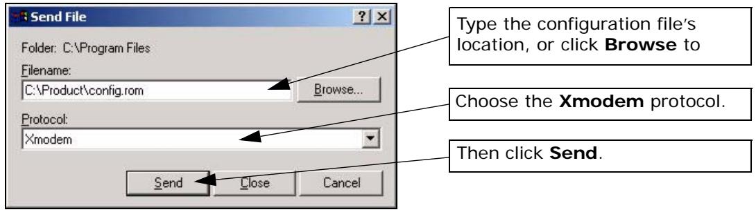
Figure 215 Successful Restoration Confirmation Screen
4 After a successful restoration you will see the following screen. Press any key to restart the P-793H v2 and return to the SMT menu.
Save to ROM
Hit any key to start system reboot.
35.5 Uploading Firmware and Configuration Files
This section shows you how to upload firmware and configuration files. You can upload configuration files by following the procedure in Section 35.4 on page 393 or by following the instructions in Menu 24.7.2 - System Maintenance - Upload System Configuration File (for console port).
Do not interrupt the file transfer process as this may PERMANENTLY DAMAGE YOUR P-793H v2.
35.5.1 Firmware File Upload
FTP is the preferred method for uploading the firmware and configuration. To use this feature, your computer must have an FTP client.
When you telnet into the P-793H v2, you will see the following screens for uploading firmware and the configuration file using FTP.
Figure 216 Menu 24.7.1: System Maintenance - Upload System Firmware
Menu 24.7.1 - System Maintenance - Upload System Firmware
To upload the system firmware, follow the procedure below:
- Launch the FTP client on your workstation.
- Type "open" and the IP address of your system. Then type "root" and SMT password as requested.
- Type "put firmwarefilename ras" where "firmwarefilename" is the name of your firmware upgrade file on your workstation and "ras" is the remote file name on the system.
- The system reboots automatically after a successful firmware upload.
For details on FTP commands, please consult the documentation of your FTP client program. For details on uploading system firmware using TFTP (note that you must remain on this menu to upload system firmware using TFTP), please see your manual.
35.5.2 Configuration File Upload
You see the following screen when you telnet into menu 24.7.2.
Figure 217 Menu 24.7.2: System Maintenance - Upload System Configuration File
Menu 24.7.2 - System Maintenance - Upload System Configuration File
To upload the system configuration file, follow the procedure below:
- Launch the FTP client on your workstation.
- Type "open" and the IP address of your system. Then type "root" and SMT password as requested.
- Type "put configurationfilename rom-0" where "configurationfilename" is the name of your system configuration file on your workstation, which will be transferred to the "rom-0" file on the system.
- The system reboots automatically after the upload system configuration file process is complete.
For details on FTP commands, please consult the documentation of your FTP client program. For details on uploading system firmware using TFTP (note that you must remain on this menu to upload system firmware using TFTP), please see your manual.
To upload the firmware and the configuration file, follow these examples
35.5.3 FTP File Upload Command from the DOS Prompt Example
1 Launch the FTP client on your computer.
2 Enter "open", followed by a space and the IP address of your P-793H v2.
3 Press [ENTER] when prompted for a username.
4 Enter your password as requested (the default is "1234").
5 Enter "bin" to set transfer mode to binary.
6 Use "put" to transfer files from the computer to the P-793H v2, for example, "put firmware.bin ras" transfers the firmware on your computer (firmware.bin) to the P-793H v2 and renames it "ras". Similarly, "put config.rom rom-0" transfers the configuration file on your computer (config.rom) to the P-793H v2 and renames it "rom-0". Likewise "get rom-0 config.rom" transfers the configuration file on the P-793H v2 to your computer and renames it "config.rom." See earlier in this chapter for more information on filename conventions.
7 Enter "quit" to exit the ftp prompt.
35.5.4 FTP Session Example of Firmware File Upload
Figure 218 FTP Session Example of Firmware File Upload
331 Enter PASS command
Password:
230 Logged in
ftp> bin
200 Type I OK
ftp> put firmware.bin ras
200 Port command okay
150 Opening data connection for STOR ras
226 File received OK
ftp: 1103936 bytes sent in 1.10Seconds 297.89Kbytes/sec.
ftp> quit
More commands (found in GUI-based FTP clients) are listed earlier in this chapter.
Refer to Section 35.3.5 on page 390 to read about configurations that disallow TFTP and FTP over WAN.
35.5.5 TFTP File Upload
The P-793H v2 also supports the uploading of firmware files using TFTP (Trivial File Transfer Protocol) over LAN. Although TFTP should work over WAN as well, it is not recommended.
To use TFTP, your computer must have both telnet and TFTP clients. To transfer the firmware and the configuration file, follow the procedure shown next.
1 Use telnet from your computer to connect to the P-793H v2 and log in. Because TFTP does not have any security checks, the P-793H v2 records the IP address of the telnet client and accepts TFTP requests only from this address.
2 Put the SMT in command interpreter (CI) mode by entering 8 in Menu 24 - System Maintenance.
3 Enter the command "sys stdio 0" to disable the console timeout, so the TFTP transfer will not be interrupted. Enter "command sys stdio 5" to restore the five-minute console timeout (default) when the file transfer is complete.
4 Launch the TFTP client on your computer and connect to the P-793H v2. Set the transfer mode to binary before starting data transfer.
5 Use the TFTP client (see the example below) to transfer files between the P-793H v2 and the computer. The file name for the firmware is "ras".
Note that the telnet connection must be active and the P-793H v2 in CI mode before and during the TFTP transfer. For details on TFTP commands (see following example), please consult the documentation of your TFTP client program. For UNIX, use "get" to transfer from the P-793H v2 to the computer, "put" the other way around, and "binary" to set binary transfer mode.
35.5.6 TFTP Upload Command Example
The following is an example TFTP command:
tftp [-i] host put firmware.bin ras
Where "i" specifies binary image transfer mode (use this mode when transferring binary files), "host" is the P-793H v2's IP address, "put" transfers the file source on the computer (firmware.bin - name of the firmware on the computer) to the file destination on the remote host (ras - name of the firmware on the P-793H v2).
Commands that you may see in GUI-based TFTP clients are listed earlier in this chapter.
35.5.7 Uploading Via Console Port
FTP or TFTP are the preferred methods for uploading firmware to your P-793H v2. However, in the event of your network being down, uploading files is only possible with a direct connection to your P-793H v2 via the console port. Uploading files via the console port under normal conditions is not recommended since FTP or TFTP is faster. Any serial communications program should work fine; however, you must use the Xmodem protocol to perform the download/upload.
35.5.8 Uploading Firmware File Via Console Port
1 Select 1 from Menu 24.7 - System Maintenance - Upload Firmware to display Menu 24.7.1 - System Maintenance - Upload System Firmware, and then follow the instructions as shown in the following screen.
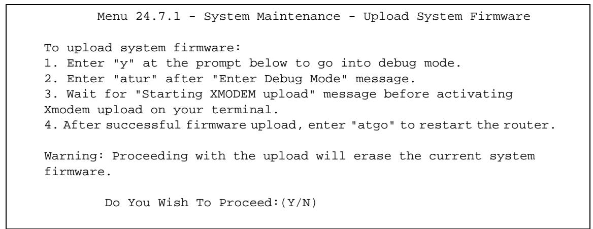
Figure 219 Menu 24.7.1 As Seen Using the Console Port
2 After the "Starting Xmodem upload" message appears, activate the Xmodem protocol on your computer. Follow the procedure as shown previously for the HyperTerminal program. The procedure for other serial communications programs should be similar.
35.5.9 Example Xmodem Firmware Upload Using HyperTerminal
Click Transfer, then Send File to display the following screen.
Figure 220 Example Xmodem Upload
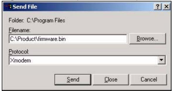
Figure 221 Menu 24.7.2 As Seen Using the Console Port
After the firmware upload process has completed, the P-793H v2 will automatically restart.
35.5.10装载器配置及安装配置
1 Select 2 from Menu 24.7 - System Maintenance - Upload Firmware to display Menu 24.7.2 - System Maintenance - Upload System Configuration File. Follow the instructions as shown in the next screen.
Menu 24.7.2 - System Maintenance - Upload System Configuration File
To upload system configuration file:
- Enter "y" at the prompt below to go into debug mode.
- Enter "at1c" after "Enter Debug Mode" message.
- Wait for "Starting XMODEM upload" message before activating Xmodem upload on your terminal.
- After successful firmware upload, enter "atgo" to restart the system.
Warning:
- Proceeding with the upload will erase the current configuration file.
- The system's console port speed (Menu 24.2.2) may change when it is restarted; please adjust your terminal's speed accordingly. The password may change (menu 23), also.
- When uploading the DEFAULT configuration file, the console port speed will be reset to 9600 bps and the password to "1234".
Do You Wish To Proceed: (Y/N)
2 After the "Starting Xmodem upload" message appears, activate the Xmodem protocol on your computer. Follow the procedure as shown previously for the HyperTerminal program. The procedure for other serial communications programs should be similar.
3 Enter "atgo" to restart the P-793H v2.
35.5.11 Example Xmodem Configuration Upload Using HyperTerminal
Click Transfer, then Send File to display the following screen.
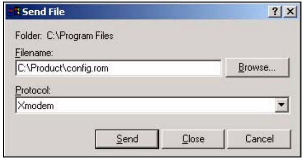
Figure 222 Example Xmodem Upload
After the configuration upload process has completed, restart the P-793H v2 by entering "atgo".
Menus 24.8 to 24.11
This chapter leads you through SMT menus 24.8 to 24.11.
36.1 Command Interpreter Mode
The Command Interpreter (CI) is a part of the main router firmware. The CI provides much of the same functionality as the SMT, while adding some low-level setup and diagnostic functions. Enter the CI from the SMT by selecting menu 24.8. Access can be by Telnet or by a connection to the console port, although some commands are only available with a console connection. See the included disk or zyxel.com for more detailed information on CI commands. Enter 8 from Menu 24 - System Maintenance.
Use of undocumented commands or misconfiguration can damage the unit and possibly render it unusable.
Figure 223 Command Mode in Menu 24
Menu 24 - System Maintenance
- System Status
- System Information and Console Port Speed
- Log and Trace
- Diagnostic
- Backup Configuration
- Restore Configuration
- Upload Firmware
- Command Interpreter Mode
- Call Control
- Time and Date Setting
- Remote Management
36.1.1 Command Syntax
The command keywords are in courier new font.
Enter the command keywords exactly as shown, do not abbreviate.
The required fields in a command are enclosed in angle brackets < .
The optional fields in a command are enclosed in square brackets [ ].
The |symbol means "or".
For example,
sys filter netbios config
means that you must specify the type of netbios filter and whether to turn it on or off.
36.1.2 Command Usage
A list of commands can be found by typing help or ? at the command prompt. Always type the full command. Type exit to return to the SMT main menu when finished.
Figure 224 Valid Commands
Copyright (c) 1994 - 2006 ZyXEL Communications Corp.
P-793H> ?
Valid commands are:
sys exit device ether
wan poe xsd1 aux
config ip ipsec ppp
bridge hdap bm lan
P-793H>
36.2 Call Control Support
The P-793H v2 provides a call control function for budget management. Please note that this menu is only applicable when Encapsulation is set to PPPoE or PPPoA in menu 4 or menu 11.1.
The budget management function allows you to set a limit on the total outgoing call time of the P-793H v2 within certain times. When the total outgoing call time exceeds the limit, the current call will be dropped and any future outgoing calls will be blocked.
Call history chronicles preceding incoming and outgoing calls.
To access the call control menu, select option 9 in menu 24 to go to Menu 24.9 - System Maintenance - Call Control, as shown in the next table.
Figure 225 Menu 24.9: System Maintenance - Call Control
Menu 24.9 - System Maintenance - Call Control
- Budget Management
36.2.1 Budget Management
Menu 24.9.1 shows the budget management statistics for outgoing calls. Enter 1 from Menu 24.9 - System Maintenance - Call Control to bring up the following menu. Not all fields are available on all models.
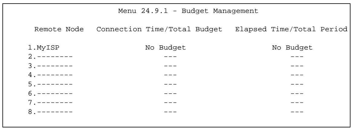
Figure 226 Menu 24.9.1 - Budget Management
The total budget is the time limit on the accumulated time for outgoing calls to a remote node. When this limit is reached, the call will be dropped and further outgoing calls to that remote node will be blocked. After each period, the total budget is reset. The default for the total budget is 0 minutes and the period is 0 hours, meaning no budget control. You can reset the accumulated connection time in this menu by entering the index of a remote node. Enter 0 to update the screen. The budget and the reset period can be configured in menu 11.1 for the remote node.
Table 140 Menu 24.9.1 - Budget Management
| FIELD | DESCRIPTION | EXAMPLE |
| Remote Node | Enter the index number of the remote node you want to reset (just one in this case) | 1 |
| Connection Time/Total Budget | This is the total connection time that has gone by (within the allocated budget that you set in menu 11.1). | 5/10 means that 5 minutes out of a total allocation of 10 minutes have lapsed. |
| Elapsed Time/Total Period | The period is the time cycle in hours that the allocation budget is reset (see menu 11.1.) The elapsed time is the time used up within this period. | 0.5/1 means that 30 minutes out of the 1-hour time period has lapsed. |
| Enter “0” to update the screen or press [ESC] to return to the previous screen. | ||
36.3 Time and Date Setting
The P-793H v2's Real Time Chip (RTC) keeps track of the time and date. There is also a software mechanism to set the time manually or get the current time and date from an external server when you turn on your P-793H v2. Menu 24.10 allows you to update the time and date settings of your P-793H v2. The real time is then displayed in the P-793H v2 error logs and firewall logs.
Select menu 24 in the main menu to open Menu 24 - System Maintenance, as shown next.
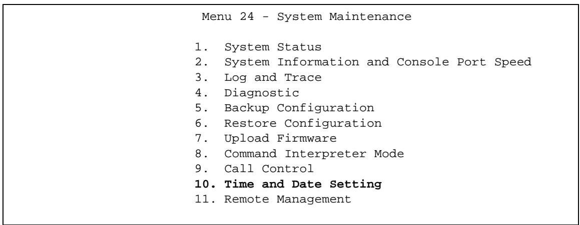
Figure 227 Menu 24: System Maintenance
Enter 10 to go to Menu 24.10 - System Maintenance - Time and Date Setting to update the time and date settings of your P-793H v2 as shown in the following screen.
Figure 228 Menu 24.10: System Maintenance - Time and Date Setting
Menu 24.10 - System Maintenance - Time and Date Setting
Time Protocol= None
Time Server Address= N/A
Current Time: 06 : 43 : 17
New Time (hh:mm:ss): 06 : 43 : 00
Current Date: 2000 - 01 - 01
New Date (yyyy-mm-dd): 2000 - 01 - 01
Time Zone= (GMT+0100) Brussels, Copenhagen, Madrid, Paris
Daylight Saving= No
Start Date (mm-nth-week-hr): Jan. - 1st - Sun.(02) - 00
End Date (mm-nth-week-hr): Jan. - 1st - Sun.(02) - 00
The following table describes the fields in this screen.
Table 141 Menu 24.10: System Maintenance - Time and Date Setting
| FIELD | DESCRIPTION |
| Time Protocol | Enter the time service protocol that your timeserver uses. Not all time servers support all protocols, so you may have to check with your ISP/ network administrator or use trial and error to find a protocol that works. The main differences between them are the format.Daytime (RFC 867) format is day/month/year/time zone of the server.Time (RFC-868) format displays a 4-byte integer giving the total number of seconds since 1970/1/1 at 0:0:0.The default, NTP (RFC-1305), is similar to Time (RFC-868).Select None to enter the new time and new date manually. |
| Time Server Address | Enter the IP address or domain name of your timeserver. Check with your ISP/network administrator if you are unsure of this information.The default is tick.sttdtime.gov.tw |
| Current Time | This field displays an updated time only when you reenter this menu. |
| New Time (hh:mm:ss) | Enter the new time in hour, minute and second format. This field is available when you select None in the Time Protocol field. |
| Current Date | This field displays an updated date only when you reenter this menu. |
| New Date (yyyy-mm-dd) | Enter the new date in year, month and day format. This field is available when you select None in the Time Protocol field. |
| Time Zone | Press [SPACE BAR] and then [ENTER] to set the time difference between your time zone and Greenwich Mean Time (GMT). |
| Daylight Saving | Daylight Saving Time is a period from late spring to early fall when many countries set their clocks ahead of normal local time by one hour to give more daylight time in the evenings. If you use daylight savings time, then choose Yes. |
| Start Date (mm-nth-week-hr) | Configure the day and time when Daylight Saving Time starts if you selected Yes in the Daylight Saving field. The hr field uses the 24 hour format. Here are a couple of examples: Daylight Saving Time starts in most parts of the United States on the first Sunday of April. Each time zone in the United States starts using Daylight Saving Time at 2 A.M. local time. So in the United States you would select Apr., 1st, Sun. and type 02 in the hr field. Daylight Saving Time starts in the European Union on the last Sunday of March. All of the time zones in the European Union start using Daylight Saving Time at the same moment (1 A.M. GMT or UTC). So in the European Union you would select Mar., Last, Sun. The time you type in the hr field depends on your time zone. In Germany for instance, you would type 02 because Germany's time zone is one hour ahead of GMT or UTC (GMT+1). |
| End Date (mm-nth-week-hr) | Configure the day and time when Daylight Saving Time ends if you selected Yes in the Daylight Saving field. The hr field uses the 24 hour format. Here are a couple of examples: Daylight Saving Time ends in the United States on the last Sunday of October. Each time zone in the United States stops using Daylight Saving Time at 2 A.M. local time. So in the United States you would select Oct., Last, Sun. and type 02 in the hr field. Daylight Saving Time ends in the European Union on the last Sunday of October. All of the time zones in the European Union stop using Daylight Saving Time at the same moment (1 A.M. GMT or UTC). So in the European Union you would select Oct., Last, Sun. The time you type in the hr field depends on your time zone. In Germany for instance, you would type 02 because Germany's time zone is one hour ahead of GMT or UTC (GMT+1). |
| Once you have filled in this menu, press [ENTER] at the message “Press ENTER to Confirm or ESC to Cancel” to save your configuration, or press [ESC] to cancel. | |
36.4 Remote Management
To disable remote management of a service, select Disable in the corresponding Server Access field. Enter 11 from menu 24 to bring up Menu 24.11 - Remote Management Control.
Figure 229 Menu 24.11 - Remote Management Control
Menu 24.11 - Remote Management Control
TELNET Server:
Server Port = 23 Server Access = ALL
Secured Client IP = 0.0.0.0
FTP Server:
Server Port = 21 Server Access = ALL
Secured Client IP = 0.0.0.0
HTTP Server:
Server Port = 80 Server Access = ALL
Secured Client IP = 0.0.0.0
The following table describes the fields in this screen.
Table 142 Menu 24.11 - Remote Management Control
| FIELD | DESCRIPTION |
| TELNET Server FTP Server HTTP Server | Each of these read-only labels denotes a service that you may use to remotely manage the P-793H v2. |
| Server Port | This field shows the port number for the service or protocol. You may change the port number if needed, but you must use the same port number to access the P-793H v2. |
| Server Access | Select the access interface (if any) by pressing [SPACE BAR], then [ENTER] to choose from: LAN only, WAN only, ALL or Disable. |
| Secured Client IP | The default 0.0.0.0 allows any client to use this service to remotely manage the P-793H v2. Enter an IP address to restrict access to a client with a matching IP address. |
| Once you have filled in this menu, press [ENTER] at the message "Press ENTER to Confirm or ESC to Cancel" to save your configuration, or press [ESC] to cancel. | |
36.4.1 Remote Management Limitations
Remote management over LAN or WAN will not work when:
1 A filter in menu 3.1 (LAN) or in menu 11.5 (WAN) is applied to block a Telnet, FTP or Web service.
2 You have disabled that service in menu 24.11.
3 The IP address in the Secure Client IP field (menu 24.11) does not match the client IP address. If it does not match, the P-793H v2 will disconnect the session immediately.
4 There is an SMT console session running.
5 There is already another remote management session with an equal or higher priority running. You may only have one remote management session running at one time.
6 There is a firewall rule that blocks it.
Use this menu to look at and configure the schedule sets in the P-793H v2.
37.1 Schedule Set Overview
Call scheduling (applicable for PPPoE encapsulation only) allows the P-793H v2 to manage a remote node and dictate when a remote node should be called and for how long. This feature is similar to the scheduler that lets you specify a time period to record a television program in a VCR or TiVo.
37.2 Schedule Setup
This menu is only applicable if your Internet connection uses PPPoE encapsulation. Use this menu to look at the schedule sets in the P-793H v2. To open this menu, enter 26 in the main menu.
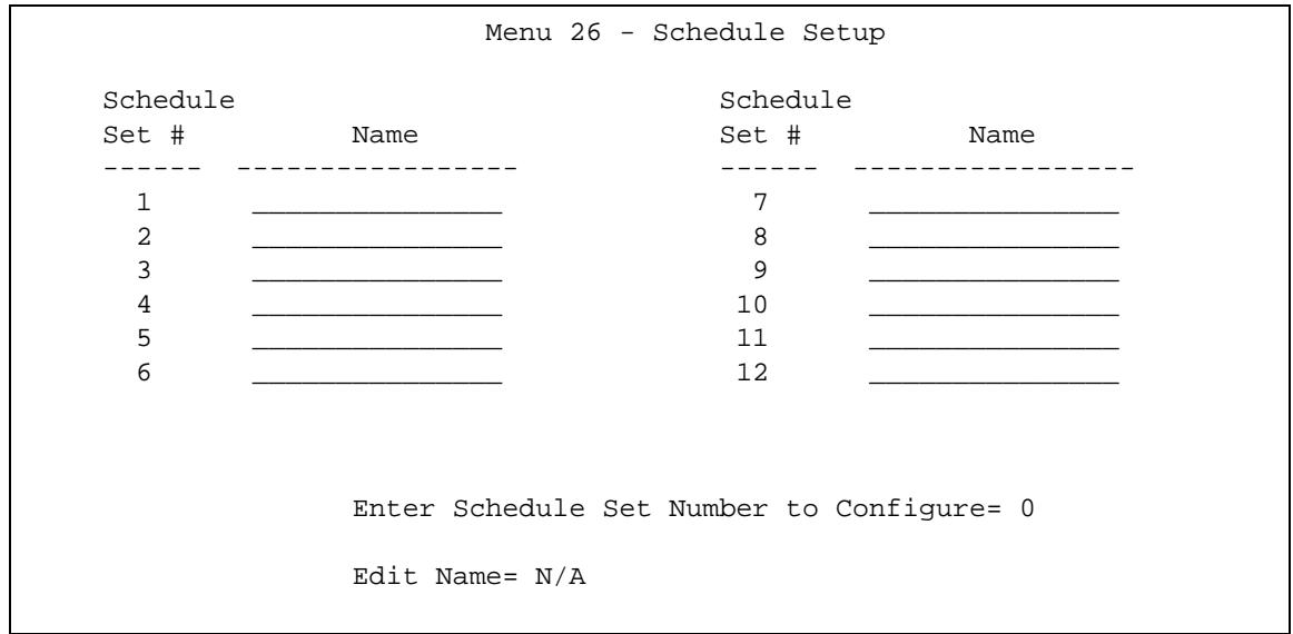
Figure 230 Menu 26: Schedule Setup
The following table describes the labels in this menu.
Table 143 Menu 26: Schedule Setup
| FIELD | DESCRIPTION |
| 1-12 | This field shows the beginning of the name of each schedule set. Lower numbered sets take precedence over higher numbered sets. This avoids scheduling conflicts. For example, if sets 1, 2, 3 and 4 in are applied in the remote node, then set 1 takes precedence over set 2, 3 and 4. |
| Enter Schedule Set Number to Configure | If you want to configure a schedule set, enter the number of the static route in this field, enter the name in the Edit Name field, and press [ENTER]. Menu 26.1 appears. If you want to delete a schedule set, enter the number of the static route in this field, leave the name blank in the Edit Name field, and press [ENTER]. |
| Edit Name | Enter the name of the schedule set you want to configure, or leave this field blank to delete the specified schedule set. |
37.3 Schedule Set Setup
This menu is only applicable if your Internet connection uses PPPoE encapsulation. Use this menu to configure the schedule sets in the P-793H v2. To open this menu, enter the number of the schedule set in the Enter Schedule Set Number to Configure field, enter the name of the schedule set in the Edit Name field, and press [ENTER] in menu 26.
Figure 231 Menu 26.1: Schedule Set Setup
Menu 26.1 Schedule Set Setup
Active= Yes
Start Date(yyyy-mm-dd) = 2000 - 01 - 01
How Often= Once
Once:
    Date(yyyy-mm-dd) = 2000 - 01 - 01
Weekdays:
    Sunday= N/A
    Monday= N/A
    Tuesday= N/A
    Wednesday= N/A
    Thursday= N/A
    Friday= N/A
    Saturday= N/A
Start Time(hh:mm) = 00 : 00
Duration(hh:mm) = 00 : 00
Action= Forced On
The following table describes the labels in this menu.
Table 144 Menu 26.1: Schedule Set Setup
| FIELD | DESCRIPTION |
| Active | Press [SPACE BAR] to select Yes or No. Choose Yes and press [ENTER] to activate the schedule set. |
| Start Date | Should this schedule set recur weekly or be used just once only? Press the [SPACE BAR] and then [ENTER] to select Once or Weekly. Both these options are mutually exclusive. If Once is selected, then all weekday settings are N/A. When Once is selected, the schedule rule deletes automatically after the scheduled time elapses. |
| How Often | Enter the start date when you wish the set to take effect in year - month-date format. Valid dates are from the present to 2036-February-5. |
| Once | |
| Date | If you selected Once in the How Often field above, then enter the date the set should activate here in year-month-date format. |
| Weekdays | If you selected Weekly in the How Often field above, then select the day(s) when the set should activate (and recur) by going to that day(s) and pressing [SPACE BAR] to select Yes, then press [ENTER]. |
| Start Time | Enter the start time when you wish the schedule set to take effect in hour-minute format. |
| Duration | Enter the maximum length of time this connection is allowed in hour-minute format. |
| Action | Forced On means that the connection is maintained whether or not there is a demand call on the line and will persist for the time period specified in the Duration field. Forced Down means that the connection is blocked whether or not there is a demand call on the line. Enable Dial-On-Demand means that this schedule permits a demand call on the line. Disable Dial-On-Demand means that this schedule prevents a demand call on the line. |
Troubleshooting
This chapter offers some suggestions to solve problems you might encounter. The potential problems are divided into the following categories.
- Power, Hardware Connections, and LEDs
- P-793H v2 Access and Login
- Internet Access
Network Connections
38.1 Power, Hardware Connections, and LEDs
The P-793H v2 does not turn on. None of the LEDs turn on.
1 Make sure the P-793H v2 is turned on.
2 Make sure you are using the power adaptor or cord included with the P-793H v2.
3 Make sure the power adaptor or cord is connected to the P-793H v2 and plugged in to an appropriate power source. Make sure the power source is turned on.
4 Turn the P-793H v2 off and on.
5 If the problem continues, contact the vendor.
One of the LEDs does not behave as expected.
1 Make sure you understand the normal behavior of the LED. See Section 1.4 on page 40.
2 Check the hardware connections.
3 Inspect your cables for damage. Contact the vendor to replace any damaged cables.
4 Turn the P-793H v2 off and on.
5 If the problem continues, contact the vendor.
38.2 P-793H v2 Access and Login
I forgot the IP address for the P-793H v2.
1 The default IP address is 192.168.1.1.
2 If you changed the IP address and have forgotten it, you might get the IP address of the P-793H v2 by looking up the IP address of the default gateway for your computer. To do this in most Windows computers, click Start > Run, enter cmd, and then enter ipconfig. The IP address of the Default Gateway might be the IP address of the P-793H v2 (it depends on the network), so enter this IP address in your Internet browser.
3 If this does not work, you have to reset the device to its factory defaults. See Section 1.5 on page 41.
I forgot the password.
1 The default admin password is 1234, and the default user password is user.
2 If this does not work, you have to reset the device to its factory defaults. See Section 1.5 on page 41.
I cannot see or access the Login screen in the web configurator.
1 Make sure you are using the correct IP address.
- The default IP address is 192.168.1.1.
-
If you changed the IP address (Section 7.2 on page 103), use the new IP address.
-
If you changed the IP address and have forgotten it, see the troubleshooting suggestions for I forgot the IP address for the P-793H v2.
2 Check the hardware connections, and make sure the LEDs are behaving as expected. See the Quick Start Guide.
3 Make sure your Internet browser does not block pop-up windows and has JavaScripts and Java enabled. See Appendix D on page 453.
- If there is a DHCP server on your network, make sure your computer is using a dynamic IP address. See Appendix C on page 429. Your P-793H v2 is a DHCP server by default.
- If there is no DHCP server on your network, make sure your computer's IP address is in the same subnet as the P-793H v2. See Appendix C on page 429.
4 Reset the device to its factory defaults, and try to access the P-793H v2 with the default IP address. See Section 1.5 on page 41.
5 If the problem continues, contact the network administrator or vendor, or try one of the advanced suggestions.
Advanced Suggestions
- Try to access the P-793H v2 using another service, such as Telnet. If you can access the P-793H v2, check the remote management settings and firewall rules to find out why the P-793H v2 does not respond to HTTP.
- If your computer is connected to the WAN port, use a computer that is connected to a ETHERNET port.
I can see the Login screen, but I cannot log in to the P-793H v2.
1 Make sure you have entered the password correctly. The default admin password is 1234, and the default user password is user. The field is case-sensitive, so make sure [Caps Lock] is not on.
2 You cannot log in to the web configurator while someone is using Telnet to access the P-793H v2. Log out of the P-793H v2 in the other session, or ask the person who is logged in to log out.
3 Turn the P-793H v2 off and on.
4 If this does not work, you have to reset the device to its factory defaults. See Section 1.5 on page 41.
I cannot Telnet to the P-793H v2.
See the troubleshooting suggestions for I cannot see or access the Login screen in the web configurator. Ignore the suggestions about your browser.
I cannot use FTP to upload / download the configuration file. / I cannot use FTP to upload new firmware.
See the troubleshooting suggestions for I cannot see or access the Login screen in the web configurator. Ignore the suggestions about your browser.
38.3 Internet Access
I cannot access the Internet.
1 Check the hardware connections, and make sure the LEDs are behaving as expected. See the Quick Start Guide and Section 1.4 on page 40.
2 Make sure you entered your ISP account information correctly in the wizard. These fields are case-sensitive, so make sure [Caps Lock] is not on.
3 Disconnect all the cables from your device, and follow the directions in the Quick Start Guide again.
4 If the problem continues, contact your ISP.
I cannot access the Internet anymore. I had access to the Internet (with the P793H v2), but my Internet connection is not available anymore.
1 Check the hardware connections, and make sure the LEDs are behaving as expected. See the Quick Start Guide and Section 1.4 on page 40.
2 Turn the P-793H v2 off and on.
3 If the problem continues, contact your ISP.
The Internet connection is slow or intermittent.
1 There might be a lot of traffic on the network. Look at the LEDs, and check Section 1.4 on page 40. If the P-793H v2 is sending or receiving a lot of information, try closing some programs that use the Internet, especially peer-to-peer applications.
2 Turn the P-793H v2 off and on.
3 If the problem continues, contact the network administrator or vendor, or try one of the advanced suggestions.
Advanced Suggestions
- Check the settings for QoS. If it is disabled, you might consider activating it. If it is enabled, you might consider raising or lowering the priority for some applications.
38.4 Network Connections
My network cannot be connected. How can I check the Internet connection status?
1 Check the LEDs on the P-793H v2 for the following situations:
- If the DSL LEDs are off, there is no DSL connection. Check if your cables are connected properly to the P-793H v2.
- If the DSL LEDs are blinking fast, the P-793H v2 is initializing the DSL line. If they keeps blinking for a long time, please reboot the device.
Note: For Internet access setup or point-to-point connections, the DSL1 and DSL2 LEDs indicate the status of a single connection (act as one LED). For point-to-2point connections, the DSL1 and DSL2 LEDs indicate the status of connection 1 and connection 2 respectively.
- If the INTERNET LED lights red, the P-793H v2 attempted to become IP connected but failed. The reason might be no DHCP response, no PPPoE response, PPPoE authentication failed, or no IP address from IPCP. Please check if you have entered the correct ISP account and password when setting up the Internet connection. If the status is the same, reboot the device. If the problem remains, please contact your vendor or customer support.
2 Excess errors may occur if the quality of your line is poor. If you hear noise on the line while making a telephone call, you should ask your local telecommunications office to check the lines in your house or apartment building and the line from your residence to your DSL service provider.
Product Specifications
Table 145 Device
| Default IP Address | 192.168.1.1 |
| Default Subnet Mask | 255.255.255.0 (24 bits) |
| Default Password | user: "user" administrator: "1234" |
| DHCP Pool | 192.168.1.33 to 192.168.1.64 |
| Dimensions (W x D x H) | 178 x 125 x 31 mm |
| Power Specification | 12V AC 1A |
| G.SHDSL Port | RJ-14 interface Data Rate: 192 Kbps - 5696 Kbps, 192-11392 kbps (4-wire mode) Line Code: TC-PAM modulation Line Impedance: 135 W Connection Loops: two pairs (4-wire) |
| Operation Temperature | 0°C ~ 40°C |
| Storage Temperature | -20° ~ 60°C |
| Operation Humidity | 20% ~ 90% RH |
| Storage Humidity | 20% ~ 95% RH |
Table 146 Firmware
| Routing/Bridge Support | IP (RFC 791) routing is supported. TCP, UDP, ICMP, IGMP v1 and v2, ARP, RIP v1, RIP v2 Transparent bridging (IEEE 802.1D) PPP BCP (RFC 3185) support |
| G.SHDSL | Connection with symmetric speed up to 11.4 Mbps in either ATM mode and EFM mode Support ITU-T G991.2 / G.994.1 standards Support ITU-T G.998.3 (G.bond) Support IPOE TC-PAM line modulation Configurable as either server or client mode OAM IEEE 802.3 chapter 57 compliant IEEE 802.3 2BASE-TL (aka 802.3ah) compliant Rate negotiating / Manually rate adaptation configuration 2-wire and 4-wire rate auto detect in either ATM mode and EFM mode. Data Rate Selections: From 192 kbps to 5700 kbps (2-wire mode) Data Rate Selections: From 192 kbps to 11400 kbps (4-wire mode) Support Bonding based on EFM and ATM |
| ATM Support | Multiple protocols over AAL5 (RFC1483) PPP over ATM (RFC 2364) ATM AAL5 supported Support 8 PVCs ATM Forum UNI3.0/4.0 PVC OAM F4/F5 Loopback, RDI, AIS UBR CBR, and nrt-VBR traffic shaping |
| EFM Support | EFM mode compliant to IEEE 802.3, G.998.3 bonding PPP over Ethernet (RFC2516) VLAN base QoS (802.1P/Q) |
| Internet Access Sharing | NAT (includes multi-to-multi NAT) / SUA, 2048 NAT sessions |
| Port restricted cone NAT | |
| SIP ALG pass-through | |
| NAT server (Port forwarding) | |
| Multi-NAT | |
| Dynamic DNS (www.dyndns.org) | |
| DHCP server/client/relay | |
| Security | User Authentication (PAP, CHAP) with PPP (RFC 1334, RFC 1994) |
| Microsoft CHAP | |
| Stateful packet inspection firewall | |
| Content filter | |
| Prevent Denial of service | |
| Access control of service | |
| Real-time attack alert and log | |
| Network Management | Web-based Configuration |
| Command-line interface | |
| Password-protected Telnet support | |
| SNMP MIB I /MIB II support | |
| TFTP & FTP firmware upgrade and configuration backup | |
| TR-069(HTTPS) | |
| VPN | IPSec VPN support |
| 10 VPN tunnels | |
| IKE/ Manual Key | |
| DES/3DES/AES Encryption (HW DES) | |
| MD5/ SHA1 Authentication | |
| FQDN | |
| NETBIOS pass-through for IPSec | |
| IPSec VPN keep-alive | |
| IPSec NAT Traversal | |
| Diagnostics Capabilities (for the following circuitry) | FLASH memory SDSL circuitry RAM LAN port |
| Others | DNS Proxy UNIX syslog |
Table 147 Firmware Features
| FEATURE | DESCRIPTION |
| Firmware Upgrade | Download new firmware (when available) from the ZyXEL web site and use the web configurator, an FTP or a TFTP tool to put it on the P-793H v2.Note: Only upload firmware for your specific model! |
| Configuration Backup & Restoration | Make a copy of the P-793H v2's configuration. You can put it back on the P-793H v2 later if you decide to revert back to an earlier configuration. |
| Network Address Translation (NAT) | Each computer on your network must have its own unique IP address. Use NAT to convert your public IP address(es) to multiple private IP addresses for the computers on your network. |
| Port Forwarding | If you have a server (mail or web server for example) on your network, you can use this feature to let people access it from the Internet. |
| DHCP (Dynamic Host Configuration Protocol) | Use this feature to have the P-793H v2 assign IP addresses, an IP default gateway and DNS servers to computers on your network. |
| Dynamic DNS Support | With Dynamic DNS (Domain Name System) support, you can use a fixed URL, www.zyxel.com for example, with a dynamic IP address. You must register for this service with a Dynamic DNS service provider. |
| IP Multicast | IP multicast is used to send traffic to a specific group of computers. The P-793H v2 supports versions 1 and 2 of IGMP (Internet Group Management Protocol) used to join multicast groups (see RFC 2236). |
| IP Alias | IP alias allows you to subdivide a physical network into logical networks over the same Ethernet interface with the P-793H v2 itself as the gateway for each subnet. |
| Time and Date | Get the current time and date from an external server when you turn on your P-793H v2. You can also set the time manually. These dates and times are then used in logs. |
| Logging and Tracing | Use packet tracing and logs for troubleshooting. You can send logs from the P-793H v2 to an external syslog server. |
| PPPoE | PPPoE mimics a dial-up Internet access connection. |
| PPTP Encapsulation | Point-to-Point Tunneling Protocol (PPTP) enables secure transfer of data through a Virtual Private Network (VPN). The P-793H v2 supports one PPTP connection at a time. |
| Universal Plug and Play (UPnP) | A UPnP-enabled device can dynamically join a network, obtain an IP address and convey its capabilities to other devices on the network. |
| Firewall | You can configure firewall on the ZyXEL Device for secure Internet access. When the firewall is on, by default, all incoming traffic from the Internet to your network is blocked unless it is initiated from your network. This means that probes from the outside to your network are not allowed, but you can safely browse the Internet and download files for example. |
Table 147 Firmware Features
| FEATURE | DESCRIPTION |
| Content Filter | The P-793H v2 blocks or allows access to web sites that you specify and blocks access to web sites with URLs that contain keywords that you specify. You can define time periods and days during which content filtering is enabled. You can also include or exclude particular computers on your network from content filtering. |
| Bandwidth Management | You can efficiently manage traffic on your network by reserving bandwidth and giving priority to certain types of traffic and/or to particular computers. |
| Remote Management | This allows you to decide whether a service (HTTP or FTP traffic for example) from a computer on a network (LAN or WAN for example) can access the P-793H v2. |
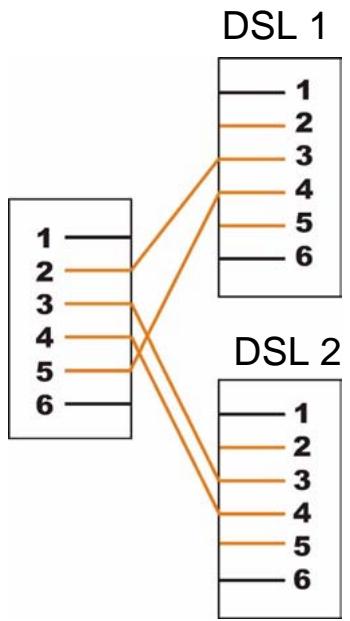
Figure 232 Y-Cable Configuration
Wall-mounting Instructions
Do the following to hang your P-793H v2 on a wall.
Note: See the product specifications appendix for the size of screws to use and how far apart to place them.
1 Locate a high position on a wall that is free of obstructions. Use a sturdy wall.
2 Drill two holes for the screws. Make sure the distance between the centers of the holes matches what is listed in the product specifications appendix.
Note: Be careful to avoid damaging pipes or cables located inside the wall when drilling holes for the screws.
3 Do not screw the screws all the way into the wall. Leave a small gap of about 0.5 cm between the heads of the screws and the wall.
4 Make sure the screws are snugly fastened to the wall. They need to hold the weight of the P-793H v2 with the connection cables.
5 Align the holes on the back of the P-793H v2 with the screws on the wall. Hang the P-793H v2 on the screws.
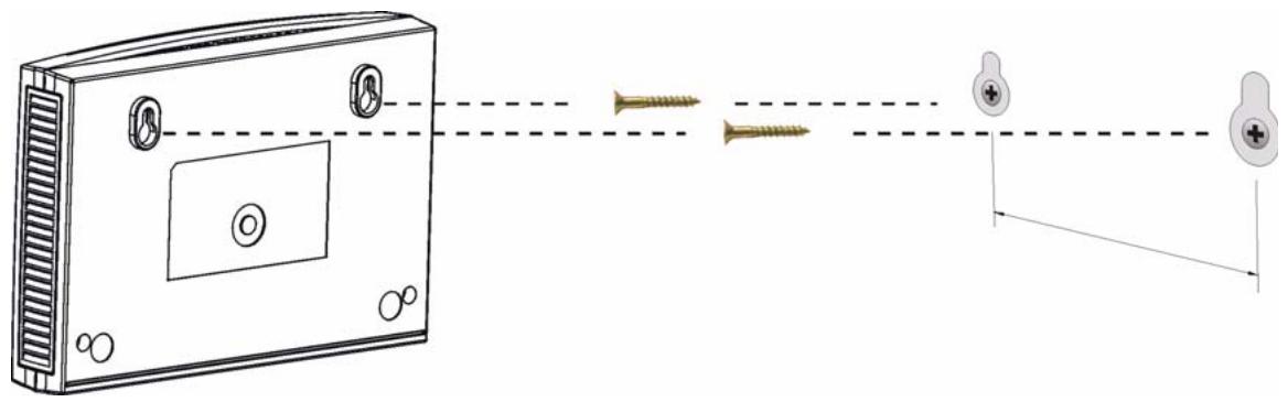
Figure 233 Wall-mounting Example
Setting up Your Computer's IP Address
All computers must have a 10M or 100M Ethernet adapter card and TCP/IP installed.
Windows 95/98/Me/NT/2000/XP/Vista, Macintosh OS 7 and later operating systems and all versions of UNIX/LINUX include the software components you need to install and use TCP/IP on your computer. Windows 3.1 requires the purchase of a third-party TCP/IP application package.
TCP/IP should already be installed on computers using Windows NT/2000/XP, Macintosh OS 7 and later operating systems.
After the appropriate TCP/IP components are installed, configure the TCP/IP settings in order to "communicate" with your network.
If you manually assign IP information instead of using dynamic assignment, make sure that your computers have IP addresses that place them in the same subnet as the P-793H v2's LAN port.
Windows 95/98/Me
Click Start, Settings, Control Panel and double-click the Network icon to open the Network window.
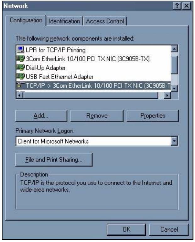
Figure 234 Windows 95/98/Me: Network: Configuration
Installing Components
The Network window Configuration tab displays a list of installed components. You need a network adapter, the TCP/IP protocol and Client for Microsoft Networks.
If you need the adapter:
1 In the Network window, click Add.
2 Select Adapter and then click Add.
3 Select the manufacturer and model of your network adapter and then click OK. If you need TCP/IP:
1 In the Network window, click Add.
2 Select Protocol and then click Add.
3 Select Microsoft from the list of manufacturers.
4 Select TCP/IP from the list of network protocols and then click OK.
If you need Client for Microsoft Networks:
1 Click Add.
2 Select Client and then click Add.
3 Select Microsoft from the list of manufacturers.
4 Select Client for Microsoft Networks from the list of network clients and then click OK.
5 Restart your computer so the changes you made take effect.
Configuring
1 In the Network window Configuration tab, select your network adapter's TCP/IP entry and click Properties
2 Click the IP Address tab.
- If your IP address is dynamic, select Obtain an IP address automatically.
- If you have a static IP address, select Specify an IP address and type your information into the IP Address and Subnet Mask fields.
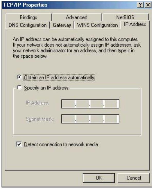
Figure 235 Windows 95/98/Me: TCP/IP Properties: IP Address
3 Click the DNS Configuration tab.
- If you do not know your DNS information, select Disable DNS.
- If you know your DNS information, select Enable DNS and type the information in the fields below (you may not need to fill them all in).

Figure 236 Windows 95/98/Me: TCP/IP Properties: DNS Configuration
4 Click the Gateway tab.
- If you do not know your gateway's IP address, remove previously installed gateways.
- If you have a gateway IP address, type it in the New gateway field and click Add.
5 Click OK to save and close the TCP/IP Properties window.
6 Click OK to close the Network window. Insert the Windows CD if prompted.
7 Turn on your P-793H v2 and restart your computer when prompted.
Verifying Settings
1 Click Start and then Run.
2 In the Run window, type "winipcfg" and then click OK to open the IP Configuration window.
3 Select your network adapter. You should see your computer's IP address, subnet mask and default gateway.
Windows 2000/NT/XP
The following example figures use the default Windows XP GUI theme.
1 Click start (Start in Windows 2000/NT), Settings, Control Panel.
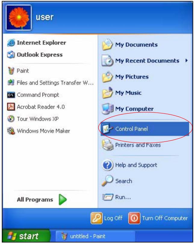
Figure 237 Windows XP: Start Menu
2 In the Control Panel, double-click Network Connections (Network and Dial-up Connections in Windows 2000/NT).
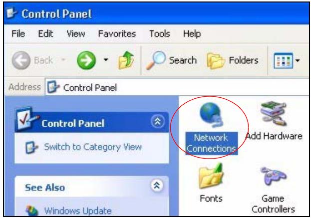
Figure 238 Windows XP: Control Panel
3 Right-click Local Area Connection and then click Properties.
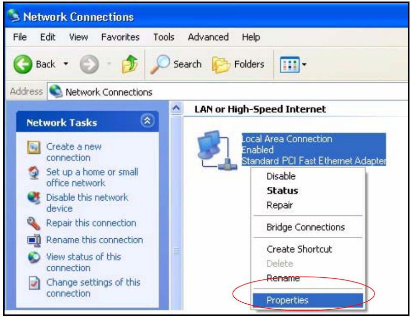
Figure 239 Windows XP: Control Panel: Network Connections: Properties
4 Select Internet Protocol (TCP/IP) (under the General tab in Win XP) and then click Properties.
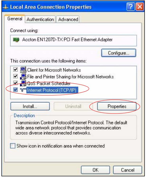
Figure 240 Windows XP: Local Area Connection Properties
5 The Internet Protocol TCP/IP Properties window opens (the General tab in Windows XP).
- If you have a dynamic IP address click Obtain an IP address automatically.
- If you have a static IP address click Use the following IP Address and fill in the IP address, Subnet mask, and Default gateway fields.
- Click Advanced.
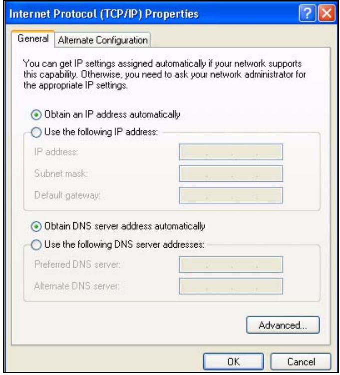
Figure 241 Windows XP: Internet Protocol (TCP/IP) Properties
6 If you do not know your gateway's IP address, remove any previously installed gateways in the IP Settings tab and click OK.
Do one or more of the following if you want to configure additional IP addresses:
- In the IP Settings tab, in IP addresses, click Add.
- In TCP/IP Address, type an IP address in IP address and a subnet mask in Subnet mask, and then click Add.
- Repeat the above two steps for each IP address you want to add.
- Configure additional default gateways in the IP Settings tab by clicking Add in Default gateways.
- In TCP/IP Gateway Address, type the IP address of the default gateway in Gateway. To manually configure a default metric (the number of transmission hops), clear the Automatic metric check box and type a metric in Metric.
- Click Add.
-
Repeat the previous three steps for each default gateway you want to add.
-
Click OK when finished.
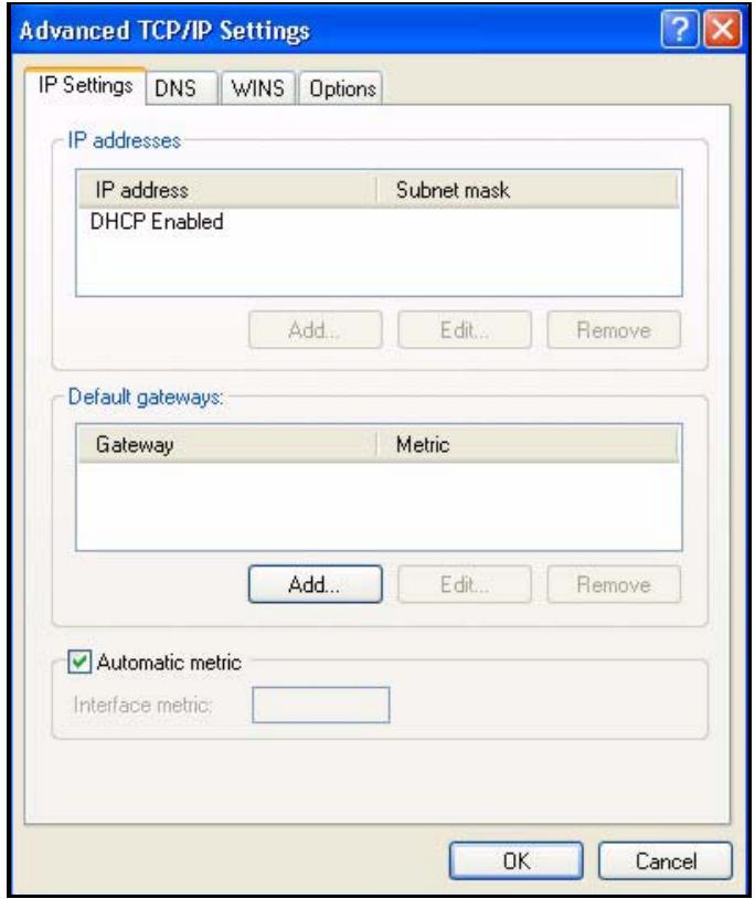
Figure 242 Windows XP: Advanced TCP/IP Properties
7 In the Internet Protocol TCP/IP Properties window (the General tab in Windows XP):
- Click Obtain DNS server address automatically if you do not know your DNS server IP address(es).
- If you know your DNS server IP address(es), click Use the following DNS server addresses, and type them in the Preferred DNS server and Alternate DNS server fields.
If you have previously configured DNS servers, click Advanced and then the DNS tab to order them.
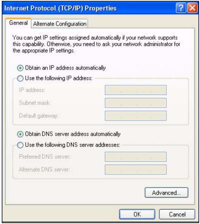
Figure 243 Windows XP: Internet Protocol (TCP/IP) Properties
8 Click OK to close the Internet Protocol (TCP/IP) Properties window.
9 Click Close (OK in Windows 2000/NT) to close the Local Area Connection Properties window.
10 Close the Network Connections window (Network and Dial-up Connections in Windows 2000/NT).
11 Turn on your P-793H v2 and restart your computer (if prompted).
Verifying Settings
1 Click Start, All Programs, Accessories and then Command Prompt.
2 In the Command Prompt window, type "ipconfig" and then press [ENTER]. You can also open Network Connections, right-click a network connection, click Status and then click the Support tab.
Windows Vista
This section shows screens from Windows Vista Enterprise Version 6.0.
1 Click the Start icon, Control Panel.
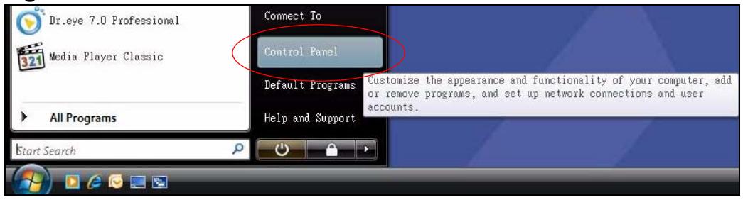
Figure 244 Windows Vista: Start Menu
2 In the Control Panel, double-click Network and Internet.
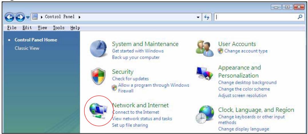
Figure 245 Windows Vista: Control Panel
3 Click Network and Sharing Center.
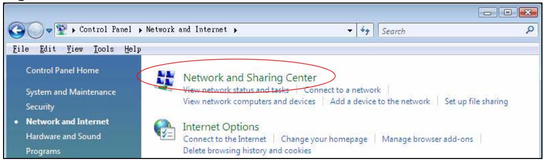
Figure 246 Windows Vista: Network And Internet
4 Click Manage network connections.
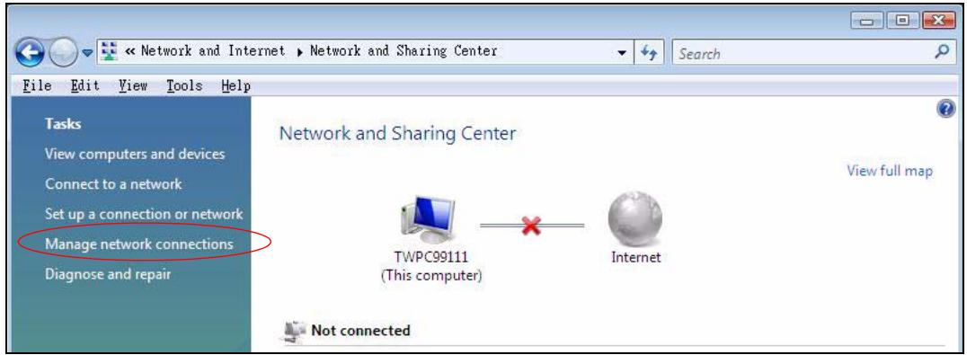
Figure 247 Windows Vista: Network and Sharing Center
5 Right-click Local Area Connection and then click Properties.
Note: During this procedure, click Continue whenever Windows displays a screen saying that it needs your permission to continue.
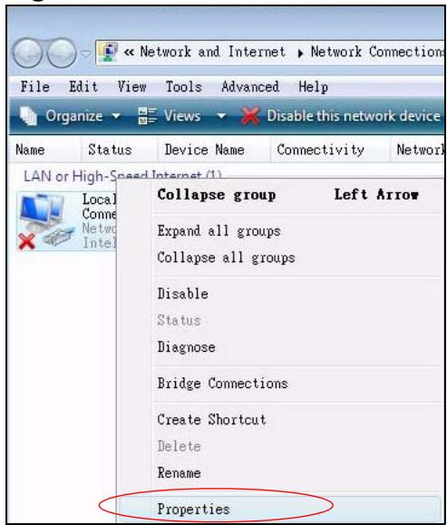
Figure 248 Windows Vista: Network and Sharing Center
6 Select Internet Protocol Version 4 (TCP/IPv4) and click Properties.
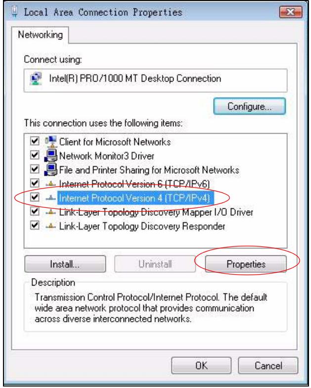
Figure 249 Windows Vista: Local Area Connection Properties
7 The Internet Protocol Version 4 (TCP/IPv4) Properties window opens (the General tab).
- If you have a dynamic IP address click Obtain an IP address automatically.
-
If you have a static IP address click Use the following IP address and fill in the IP address, Subnet mask, and Default gateway fields.
-
Click Advanced.

Figure 250 Windows Vista: Internet Protocol Version 4 (TCP/IPv4) Properties
8 If you do not know your gateway's IP address, remove any previously installed gateways in the IP Settings tab and click OK.
Do one or more of the following if you want to configure additional IP addresses:
- In the IP Settings tab, in IP addresses, click Add.
- In TCP/IP Address, type an IP address in IP address and a subnet mask in Subnet mask, and then click Add.
- Repeat the above two steps for each IP address you want to add.
- Configure additional default gateways in the IP Settings tab by clicking Add in Default gateways.
- In TCP/IP Gateway Address, type the IP address of the default gateway in Gateway. To manually configure a default metric (the number of transmission hops), clear the Automatic metric check box and type a metric in Metric.
- Click Add.
-
Repeat the previous three steps for each default gateway you want to add.
-
Click OK when finished.
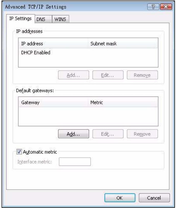
Figure 251 Windows Vista: Advanced TCP/IP Properties
9 In the Internet Protocol Version 4 (TCP/IPv4) Properties window, (the General tab):
- Click Obtain DNS server address automatically if you do not know your DNS server IP address(es).
- If you know your DNS server IP address(es), click Use the following DNS server addresses, and type them in the Preferred DNS server and Alternate DNS server fields.
If you have previously configured DNS servers, click Advanced and then the DNS tab to order them.
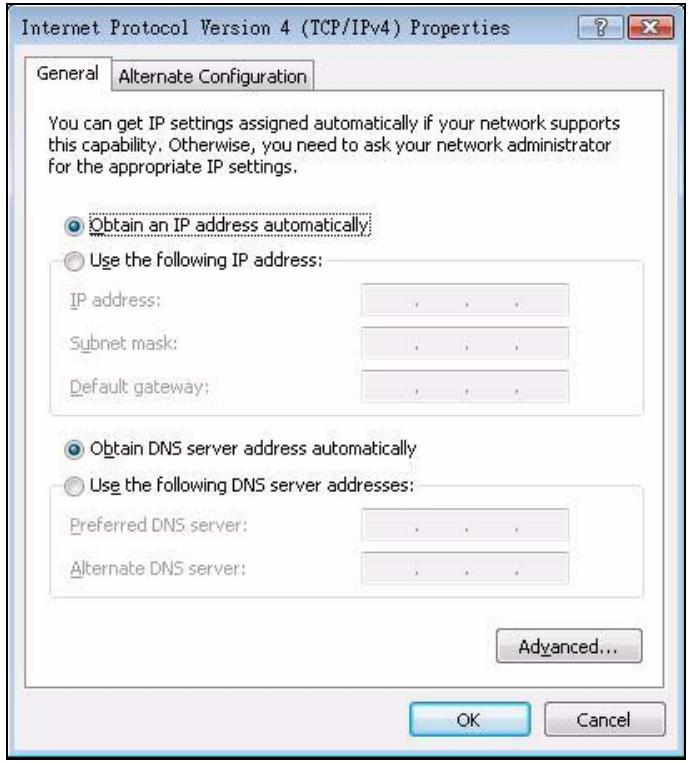
Figure 252 Windows Vista: Internet Protocol Version 4 (TCP/IPv4) Properties
10 Click OK to close the Internet Protocol Version 4 (TCP/IPv4) Properties window.
11 Click Close to close the Local Area Connection Properties window.
12 Close the Network Connections window.
13 Turn on your P-793H v2 and restart your computer (if prompted).
Verifying Settings
1 Click Start, All Programs, Accessories and then Command Prompt.
2 In the Command Prompt window, type "ipconfig" and then press [ENTER]. You can also open Network Connections, right-click a network connection, click Status and then click the Support tab.
Macintosh OS 8/9
1 Click the Apple menu, Control Panel and double-click TCP/IP to open the TCP/IP Control Panel.
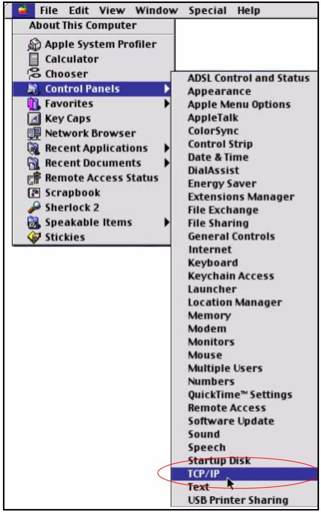
Figure 253 Macintosh OS 8/9: Apple Menu
2 Select Ethernet built-in from the Connect via list.

Figure 254 Macintosh OS 8/9: TCP/IP
3 For dynamically assigned settings, select Using DHCP Server from the Configure: list.
4 For statically assigned settings, do the following:
From the Configure box, select Manually.
- Type your IP address in the IP Address box.
- Type your subnet mask in the Subnet mask box.
- Type the IP address of your P-793H v2 in the Router address box.
5 Close the TCP/IP Control Panel.
6 Click Save if prompted, to save changes to your configuration.
7 Turn on your P-793H v2 and restart your computer (if prompted).
Verifying Settings
Check your TCP/IP properties in the TCP/IP Control Panel window.
Macintosh OS X
1 Click the Apple menu, and click System Preferences to open the System Preferences window.
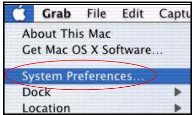
Figure 255 Macintosh OS X: Apple Menu
2 Click Network in the icon bar.
- Select Automatic from the Location list.
- Select Built-in Ethernet from the Show list.
- Click the TCP/IP tab.
3 For dynamically assigned settings, select Using DHCP from the Configure list.
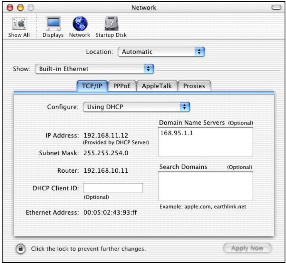
Figure 256 Macintosh OS X: Network
4 For statically assigned settings, do the following:
From the Configure box, select Manually.
- Type your IP address in the IP Address box.
- Type your subnet mask in the Subnet mask box.
- Type the IP address of your P-793H v2 in the Router address box.
5 Click Apply Now and close the window.
6 Turn on your P-793H v2 and restart your computer (if prompted).
Verifying Settings
Check your TCP/IP properties in the Network window.
Linux
This section shows you how to configure your computer's TCP/IP settings in Red Hat Linux 9.0. Procedure, screens and file location may vary depending on your Linux distribution and release version.
Note: Make sure you are logged in as the root administrator.
Using the K Desktop Environment (KDE)
Follow the steps below to configure your computer IP address using the KDE.
1 Click the Red Hat button (located on the bottom left corner), select System Setting and click Network.
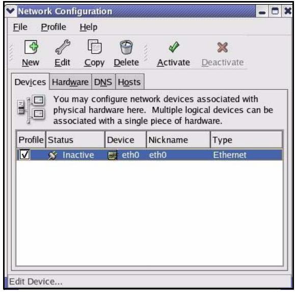
Figure 257 Red Hat 9.0: KDE: Network Configuration: Devices
2 Double-click on the profile of the network card you wish to configure. The Ethernet Device General screen displays as shown.
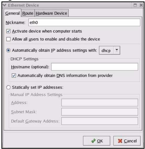
Figure 258 Red Hat 9.0: KDE: Ethernet Device: General
- If you have a dynamic IP address, click Automatically obtain IP address settings with and select dhcp from the drop down list.
- If you have a static IP address, click statically set IP Addresses and fill in the Address, Subnet mask, and Default Gateway Address fields.
3 Click OK to save the changes and close the Ethernet Device General screen.
4 If you know your DNS server IP address(es), click the DNS tab in the Network Configuration screen. Enter the DNS server information in the fields provided.
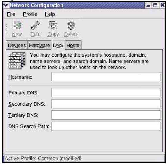
Figure 259 Red Hat 9.0: KDE: Network Configuration: DNS
5 Click the Devices tab.
6 Click the Activate button to apply the changes. The following screen displays. Click Yes to save the changes in all screens.
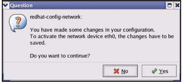
Figure 260 Red Hat 9.0: KDE: Network Configuration: Activate
7 After the network card restart process is complete, make sure the Status is Active in the Network Configuration screen.
Using Configuration Files
Follow the steps below to edit the network configuration files and set your computer IP address.
1 Assuming that you have only one network card on the computer, locate the ifconfig-eth0 configuration file (where eth0 is the name of the Ethernet card). Open the configuration file with any plain text editor.
- If you have a dynamic IP address, enter dhcp in the BOOTPROTO= field. The following figure shows an example.
Figure 261 Red Hat 9.0: Dynamic IP Address Setting in ifconfig-eth0
DEVICE=eth0
ONBOOT=yes
BOOTPROTO=dhcp
USERCTL=no
PEERDNS=yes
TYPE=Ethernet
- If you have a static IP address, enter static in the BOOTPROTO= field. Type IPADDR= followed by the IP address (in dotted decimal notation) and type NETMASK= followed by the subnet mask. The following example shows an example where the static IP address is 192.168.1.10 and the subnet mask is 255.255.255.0.
Figure 262 Red Hat 9.0: Static IP Address Setting in ifconfig-eth0
DEVICE eth0
ONBOOT yes
BOOTPROTO static
IPADDR = 192.168.1.10 NETMASK = 255.255.255.0 USERCTL no
PEERDNS yes
TYPE Ethernet
2 If you know your DNS server IP address(es), enter the DNS server information in the resolv.conf file in the /etc directory. The following figure shows an example where two DNS server IP addresses are specified.
Figure 263 Red Hat 9.0: DNS Settings in resolv.conf
nameserver 172.23.5.1
nameserver 172.23.5.2
3 After you edit and save the configuration files, you must restart the network card. Enter ./network restart in the /etc/rc.d/init.d directory. The following figure shows an example.
Figure 264 Red Hat 9.0: Restart Ethernet Card
[root@localhost init.d]# network restart Shutting down interface eth0: [OK] Shutting down loopback interface: [OK] Setting network parameters: [OK] Bringing up loopback interface: [OK] Bringing up interface eth0: [OK]
Verifying Settings
Enter ifconfig in a terminal screen to check your TCP/IP properties.
Figure 265 Red Hat 9.0: Checking TCP/IP Properties
[root@localhost]# ifconfig
eth0 Link encaps:Ethernet HWaddr 00:50:BA:72:5B:44 inlet addr:172.23.19.129 Bcast:172.23.19.255 Mask:255.255.255.0 UP BROADCAST RUNNING MULTICAST MTU:1500 Metric:1 RX packets:717 errors:0 dropped:0 overruns:0 frame:0 TX packets:13 errors:0 dropped:0 overruns:0 carrier:0 collisions:0 txqueuelen:100 RX bytes:730412 (713.2 Kb) TX bytes:1570 (1.5 Kb) Interrupt:10 Base address:0x1000
[root@localhost]#
Pop-up Windows, JavaScript and Java Permissions
In order to use the web configurator you need to allow:
- Web browser pop-up windows from your device.
- JavaScripts (enabled by default).
- Java permissions (enabled by default).
Note: Internet Explorer 6 screens are used here. Screens for other Internet Explorer versions may vary.
Internet Explorer Pop-up Blockers
You may have to disable pop-up blocking to log into your device.
Either disable pop-up blocking (enabled by default in Windows XP SP (Service Pack) 2) or allow pop-up blocking and create an exception for your device's IP address.
Disable Pop-up Blockers
1 In Internet Explorer, select Tools, Pop-up Blocker and then select Turn Off Pop-up Blocker.
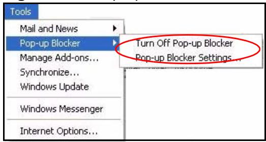
Figure 266 Pop-up Blocker
You can also check if pop-up blocking is disabled in the Pop-up Blocker section in the Privacy tab.
1 In Internet Explorer, select Tools, Internet Options, Privacy.
2 Clear the Block pop-ups check box in the Pop-up Blocker section of the screen. This disables any web pop-up blockers you may have enabled.
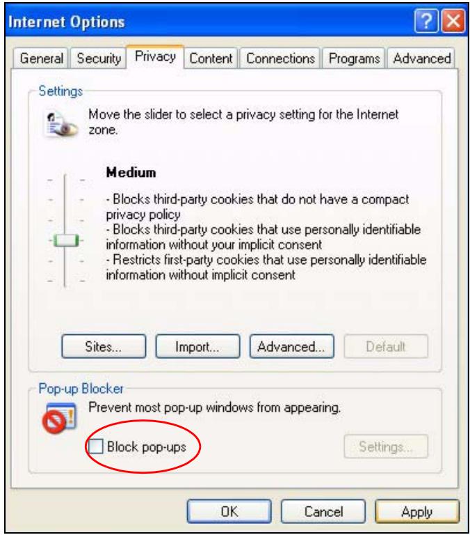
Figure 267 Internet Options: Privacy
3 Click Apply to save this setting.
Enable Pop-up Blockers with Exceptions
Alternatively, if you only want to allow pop-up windows from your device, see the following steps.
1 In Internet Explorer, select Tools, Internet Options and then the Privacy tab.
2 Select Settings...to open the Pop-up Blocker Settings screen.
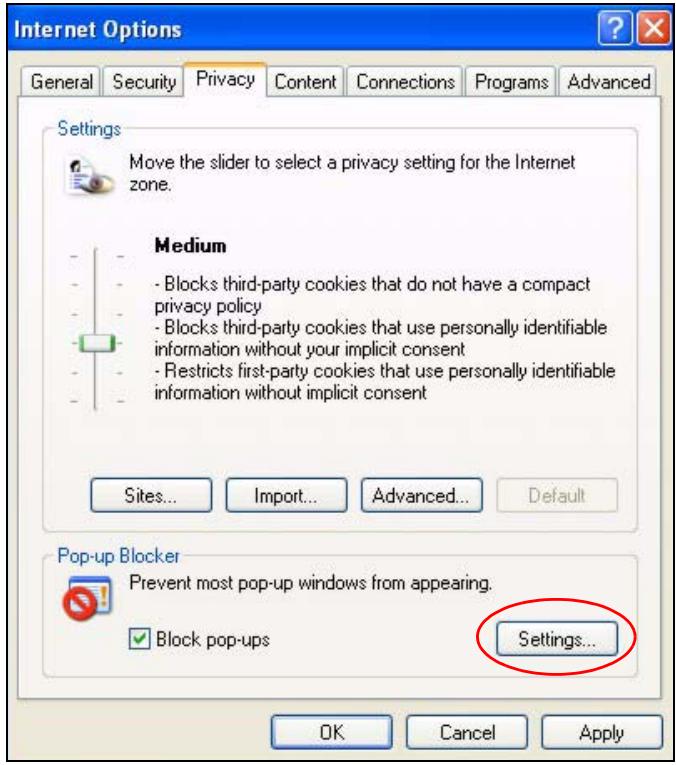
Figure 268 Internet Options: Privacy
3 Type the IP address of your device (the web page that you do not want to have blocked) with the prefix "http://". For example, http://192.168.167.1.
4 Click Add to move the IP address to the list of Allowed sites.
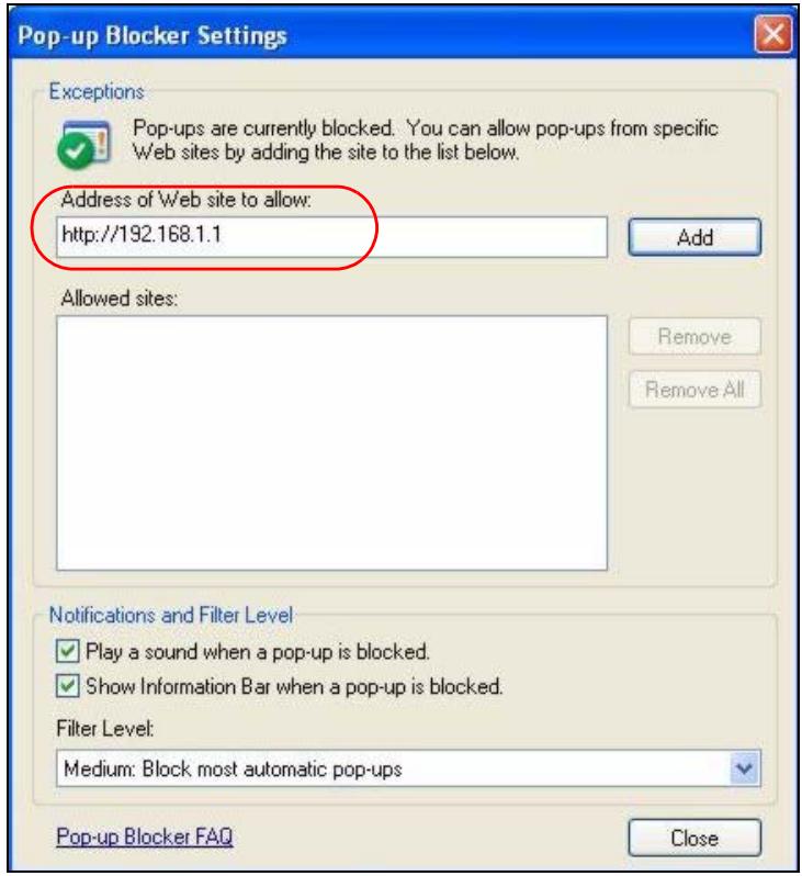
Figure 269 Pop-up Blocker Settings
5 Click Close to return to the Privacy screen.
6 Click Apply to save this setting.
JavaScript
If pages of the web configurator do not display properly in Internet Explorer, check that JavaScripts are allowed.
1 In Internet Explorer, click Tools, Internet Options and then the Security tab.
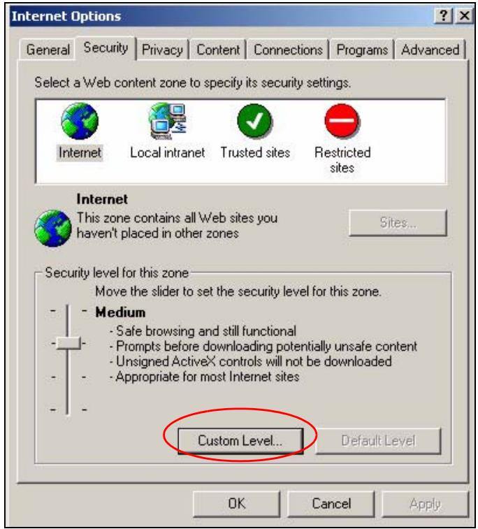
Figure 270 Internet Options: Security
2 Click the Custom Level... button.
3 Scroll down to Scripting.
4 Under Active scripting make sure that Enable is selected (the default).
5 Under Scripting of Java applets make sure that Enable is selected (the default).
6 Click OK to close the window.
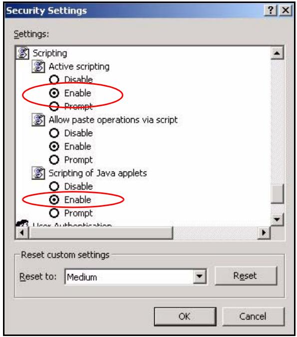
Figure 271 Security Settings - Java Scripting
Java Permissions
1 From Internet Explorer, click Tools, Internet Options and then the Security tab.
2 Click the Custom Level... button.
3 Scroll down to Microsoft VM.
4 Under Java permissions make sure that a safety level is selected.
5 Click OK to close the window.
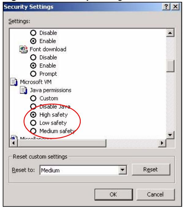
Figure 272 Security Settings - Java
JAVA (Sun)
1 From Internet Explorer, click Tools, Internet Options and then the Advanced tab.
2 Make sure that Use Java 2 for
3 Click OK to close the window.
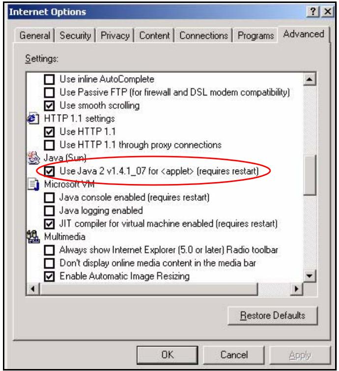
Figure 273 Java (Sun)
Mozilla Firefox
Mozilla Firefox 2.0 screens are used here. Screens for other versions may vary.
You can enable Java, Javascripts and pop-ups in one screen. Click Tools, then click Options in the screen that appears.
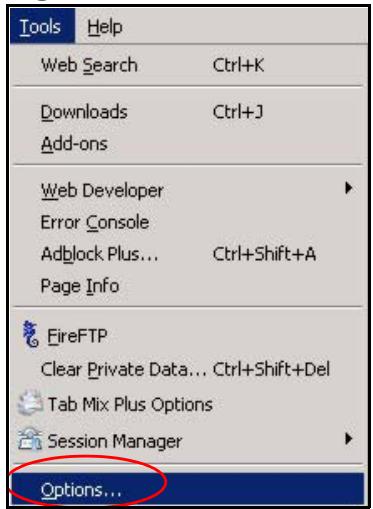
Figure 274 Mozilla Firefox: Tools > Options
Click Content.to show the screen below. Select the check boxes as shown in the following screen.
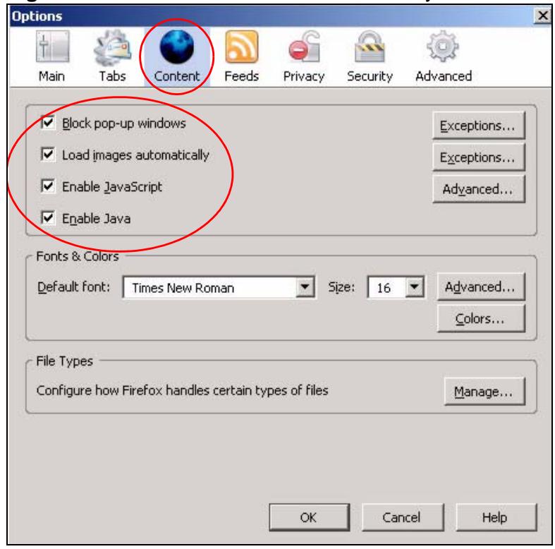
Figure 275 Mozilla Firefox Content Security
IP Addresses and Subnetting
This appendix introduces IP addresses and subnet masks.
IP addresses identify individual devices on a network. Every networking device (including computers, servers, routers, printers, etc.) needs an IP address to communicate across the network. These networking devices are also known as hosts.
Subnet masks determine the maximum number of possible hosts on a network. You can also use subnet masks to divide one network into multiple sub-networks.
Introduction to IP Addresses
One part of the IP address is the network number, and the other part is the host ID. In the same way that houses on a street share a common street name, the hosts on a network share a common network number. Similarly, as each house has its own house number, each host on the network has its own unique identifying number - the host ID. Routers use the network number to send packets to the correct network, while the host ID determines to which host on the network the packets are delivered.
Structure
An IP address is made up of four parts, written in dotted decimal notation (for example, 192.168.1.1). Each of these four parts is known as an octet. An octet is an eight-digit binary number (for example 11000000, which is 192 in decimal notation).
Therefore, each octet has a possible range of 00000000 to 11111111 in binary, or 0 to 255 in decimal.
The following figure shows an example IP address in which the first three octets (192.168.1) are the network number, and the fourth octet (16) is the host ID.
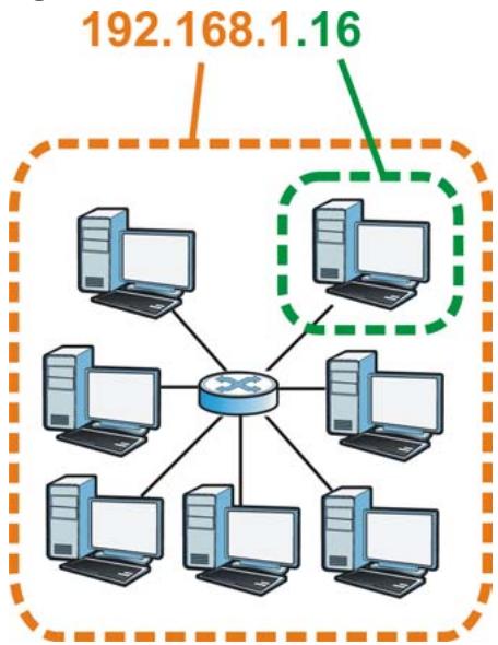
Figure 276 Network Number and Host ID
How much of the IP address is the network number and how much is the host ID varies according to the subnet mask.
Subnet Masks
A subnet mask is used to determine which bits are part of the network number, and which bits are part of the host ID (using a logical AND operation). The term "subset" is short for "sub-network".
A subnet mask has 32 bits. If a bit in the subnet mask is a "1" then the corresponding bit in the IP address is part of the network number. If a bit in the subnet mask is "0" then the corresponding bit in the IP address is part of the host ID.
The following example shows a subnet mask identifying the network number (in bold text) and host ID of an IP address (192.168.1.2 in decimal).
Table 148 Subnet Masks
| 1ST OCTET: (192) | 2ND OCTET: (168) | 3RD OCTET: (1) | 4TH OCTET (2) | |
| IP Address (Binary) | 11000000 | 10101000 | 00000001 | 00000010 |
| Subnet Mask (Binary) | 11111111 | 11111111 | 11111111 | 00000000 |
| Network Number | 11000000 | 10101000 | 00000001 | |
| Host ID | 00000010 |
By convention, subnet masks always consist of a continuous sequence of ones beginning from the leftmost bit of the mask, followed by a continuous sequence of zeros, for a total number of 32 bits.
Subnet masks can be referred to by the size of the network number part (the bits with a "1" value). For example, an "8-bit mask" means that the first 8 bits of the mask are ones and the remaining 24 bits are zeroes.
Subnet masks are expressed in dotted decimal notation just like IP addresses. The following examples show the binary and decimal notation for 8-bit, 16-bit, 24-bit and 29-bit subnet masks.
Table 149 Subnet Masks
| BINARY | DECIMAL | ||||
| 1ST OCTET | 2ND OCTET | 3RD OCTET | 4TH OCTET | ||
| 8-bit mask | 11111111 | 00000000 | 00000000 | 00000000 | 255.0.0.0 |
| 16-bit mask | 11111111 | 11111111 | 00000000 | 00000000 | 255.255.0.0 |
| 24-bit mask | 11111111 | 11111111 | 11111111 | 00000000 | 255.255.255.0 |
| 29-bit mask | 11111111 | 11111111 | 11111111 | 11111000 | 255.255.255.248 |
Network Size
The size of the network number determines the maximum number of possible hosts you can have on your network. The larger the number of network number bits, the smaller the number of remaining host ID bits.
An IP address with host IDs of all zeros is the IP address of the network (192.168.1.0 with a 24-bit subnet mask, for example). An IP address with host IDs of all ones is the broadcast address for that network (192.168.1.255 with a 24-bit subnet mask, for example).
As these two IP addresses cannot be used for individual hosts, calculate the maximum number of possible hosts in a network as follows:
Table 150 Maximum Host Numbers
| SUBNET MASK | HOST ID SIZE | MAXIMUM NUMBER OF HOSTS | ||
| 8 bits | 255.0.0.0 | 24 bits | \( 2^{24} - 2 \) | 16777214 |
| 16 bits | 255.255.0.0 | 16 bits | \( 2^{16} - 2 \) | 65534 |
| 24 bits | 255.255.255.0 | 8 bits | \( 2^8 - 2 \) | 254 |
| 29 bits | 255.255.255.2 48 | 3 bits | \( 2^3 - 2 \) | 6 |
Notation
Since the mask is always a continuous number of ones beginning from the left, followed by a continuous number of zeros for the remainder of the 32 bit mask, you can simply specify the number of ones instead of writing the value of each octet. This is usually specified by writing a “/” followed by the number of bits in the mask after the address.
For example, 192.1.1.0 /25 is equivalent to saying 192.1.1.0 with subnet mask 255.255.255.128.
The following table shows some possible subnet masks using both notations.
Table 151 Alternative Subnet Mask Notation
| SUBNET MASK | ALTERNATIVE NOTATION | LAST OCTET (BINARY) | LAST OCTET (DECIMAL) |
| 255.255.255.0 | /24 | 0000 0000 | 0 |
| 255.255.255.128 | /25 | 1000 0000 | 128 |
| 255.255.255.192 | /26 | 1100 0000 | 192 |
| 255.255.255.224 | /27 | 1110 0000 | 224 |
| 255.255.255.240 | /28 | 1111 0000 | 240 |
| 255.255.255.248 | /29 | 1111 1000 | 248 |
| 255.255.255.252 | /30 | 1111 1100 | 252 |
Subnetting
You can use subnetting to divide one network into multiple sub-networks. In the following example a network administrator creates two sub-networks to isolate a group of servers from the rest of the company network for security reasons.
In this example, the company network address is 192.168.1.0. The first three octets of the address (192.168.1) are the network number, and the remaining octet is the host ID, allowing a maximum of 2^8 - 2 or 254 possible hosts.
The following figure shows the company network before subnetting.
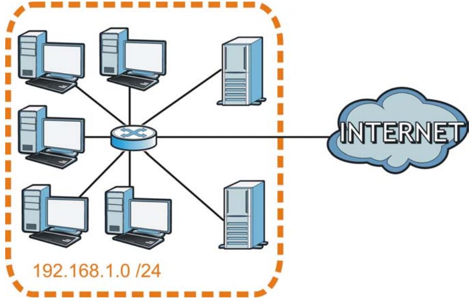
Figure 277 Subnetting Example: Before Subnetting
You can "borrow" one of the host ID bits to divide the network 192.168.1.0 into two separate sub-networks. The subnet mask is now 25 bits (255.255.255.128 or /25).
The "borrowed" host ID bit can have a value of either 0 or 1, allowing two subnets; 192.168.1.0 /25 and 192.168.1.128 /25.
The following figure shows the company network after subnetting. There are now two sub-networks, A and B.
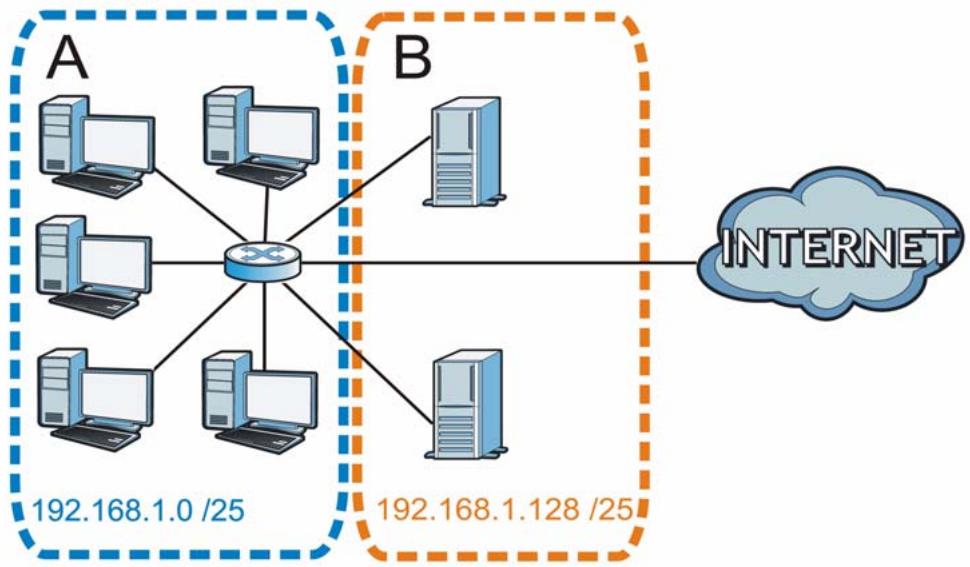
Figure 278 Subnetting Example: After Subnetting
In a 25-bit subnet the host ID has 7 bits, so each sub-network has a maximum of 2^7 - 2 or 126 possible hosts (a host ID of all zeroes is the subnet's address itself, all ones is the subnet's broadcast address).
192.168.1.0 with mask 255.255.255.128 is subnet A itself, and 192.168.1.127 with mask 255.255.255.128 is its broadcast address. Therefore, the lowest IP address that can be assigned to an actual host for subnet A is 192.168.1.1 and the highest is 192.168.1.126.
Similarly, the host ID range for subnet B is 192.168.1.129 to 192.168.1.254.
Example: Four Subnets
The previous example illustrated using a 25-bit subnet mask to divide a 24-bit address into two subnets. Similarly, to divide a 24-bit address into four subnets, you need to "borrow" two host ID bits to give four possible combinations (00, 01, 10 and 11). The subnet mask is 26 bits
(11111111.11111111.11111111.11000000) or 255.255.255.192.
Each subnet contains 6 host ID bits, giving 2^6 - 2 or 62 hosts for each subnet (a host ID of all zeroes is the subnet itself, all ones is the subnet's broadcast address).
Table 152 Subnet 1
| IP/SUBNET MASK | NETWORK NUMBER | LAST OCTET BIT VALUE |
| IP Address (Decimal) | 192.168.1. | 0 |
| IP Address (Binary) | 11000000.10101000.00000001. | 00000000 |
| Subnet Mask (Binary) | 11111111.11111111.11111111. | 11000000 |
| Subnet Address: 192.168.1.0 | Lowest Host ID: 192.168.1.1 | |
| Broadcast Address: 192.168.1.63 | Highest Host ID: 192.168.1.62 | |
Table 153 Subnet 2
| IP/SUBNET MASK | NETWORK NUMBER | LAST OCTET BIT VALUE |
| IP Address | 192.168.1. | 64 |
| IP Address (Binary) | 11000000.10101000.00000001. | 01000000 |
| Subnet Mask (Binary) | 11111111.11111111.11111111. | 11000000 |
| Subnet Address: 192.168.1.64 | Lowest Host ID: 192.168.1.65 | |
| Broadcast Address: 192.168.1.127 | Highest Host ID: 192.168.1.126 | |
Table 154 Subnet 3
| IP/SUBNET MASK | NETWORK NUMBER | LAST OCTET BIT VALUE |
| IP Address | 192.168.1. | 128 |
| IP Address (Binary) | 11000000.10101000.00000001. | 10000000 |
| Subnet Mask (Binary) | 11111111.11111111.11111111. | 11000000 |
| Subnet Address: 192.168.1.128 | Lowest Host ID: 192.168.1.129 | |
| Broadcast Address: 192.168.1.191 | Highest Host ID: 192.168.1.190 | |
Table 155 Subnet 4
| IP/SUBNET MASK | NETWORK NUMBER | LAST OCTET BIT VALUE |
| IP Address | 192.168.1. | 192 |
| IP Address (Binary) | 11000000.10101000.00000001 . | 11000000 |
| Subnet Mask (Binary) | 11111111.11111111.11111111 . | 11000000 |
| Subnet Address: 192.168.1.192 | Lowest Host ID: 192.168.1.193 | |
| Broadcast Address: 192.168.1.255 | Highest Host ID: 192.168.1.254 | |
Example: Eight Subnets
Similarly, use a 27-bit mask to create eight subnets (000, 001, 010, 011, 100, 101, 110 and 111).
The following table shows IP address last octet values for each subnet.
Table 156 Eight Subnets
| SUBNET | SUBNET ADDRESS | FIRST ADDRESS | LAST ADDRESS | BROADCAST ADDRESS |
| 1 | 0 | 1 | 30 | 31 |
| 2 | 32 | 33 | 62 | 63 |
| 3 | 64 | 65 | 94 | 95 |
| 4 | 96 | 97 | 126 | 127 |
| 5 | 128 | 129 | 158 | 159 |
| 6 | 160 | 161 | 190 | 191 |
| 7 | 192 | 193 | 222 | 223 |
| 8 | 224 | 225 | 254 | 255 |
Subnet Planning
The following table is a summary for subnet planning on a network with a 24-bit network number.
Table 157 24-bit Network Number Subnet Planning
| NO. “BORROWED” HOST BITS | SUBNET MASK | NO. SUBNETS | NO. HOSTS PER SUBNET |
| 1 | 255.255.255.128 (/25) | 2 | 126 |
| 2 | 255.255.255.192 (/26) | 4 | 62 |
| 3 | 255.255.255.224 (/27) | 8 | 30 |
| 4 | 255.255.255.240 (/28) | 16 | 14 |
| 5 | 255.255.255.248 (/29) | 32 | 6 |
| 6 | 255.255.255.252 (/30) | 64 | 2 |
| 7 | 255.255.255.254 (/31) | 128 | 1 |
The following table is a summary for subnet planning on a network with a 16-bit network number.
Table 158 16-bit Network Number Subnet Planning
| NO. “BORROWED” HOST BITS | SUBNET MASK | NO. SUBNETS | NO. HOSTS PER SUBNET |
| 1 | 255.255.128.0 (/17) | 2 | 32766 |
| 2 | 255.255.192.0 (/18) | 4 | 16382 |
| 3 | 255.255.224.0 (/19) | 8 | 8190 |
| 4 | 255.255.240.0 (/20) | 16 | 4094 |
| 5 | 255.255.248.0 (/21) | 32 | 2046 |
| 6 | 255.255.252.0 (/22) | 64 | 1022 |
| 7 | 255.255.254.0 (/23) | 128 | 510 |
| 8 | 255.255.255.0 (/24) | 256 | 254 |
| 9 | 255.255.255.128 (/25) | 512 | 126 |
| 10 | 255.255.255.192 (/26) | 1024 | 62 |
| 11 | 255.255.255.224 (/27) | 2048 | 30 |
| 12 | 255.255.255.240 (/28) | 4096 | 14 |
| 13 | 255.255.255.248 (/29) | 8192 | 6 |
| 14 | 255.255.255.252 (/30) | 16384 | 2 |
| 15 | 255.255.255.254 (/31) | 32768 | 1 |
Configuring IP Addresses
Where you obtain your network number depends on your particular situation. If the ISP or your network administrator assigns you a block of registered IP
addresses, follow their instructions in selecting the IP addresses and the subnet mask.
If the ISP did not explicitly give you an IP network number, then most likely you have a single user account and the ISP will assign you a dynamic IP address when the connection is established. If this is the case, it is recommended that you select a network number from 192.168.0.0 to 192.168.255.0. The Internet Assigned Number Authority (IANA) reserved this block of addresses specifically for private use; please do not use any other number unless you are told otherwise. You must also enable Network Address Translation (NAT) on the P-793H v2.
Once you have decided on the network number, pick an IP address for your P-793H v2 that is easy to remember (for instance, 192.168.1.1) but make sure that no other device on your network is using that IP address.
The subnet mask specifies the network number portion of an IP address. Your P-793H v2 will compute the subnet mask automatically based on the IP address that you entered. You don't need to change the subnet mask computed by the P-793H v2 unless you are instructed to do otherwise.
Private IP Addresses
Every machine on the Internet must have a unique address. If your networks are isolated from the Internet (running only between two branch offices, for example) you can assign any IP addresses to the hosts without problems. However, the Internet Assigned Numbers Authority (IANA) has reserved the following three blocks of IP addresses specifically for private networks:
10.0.0.0 -10.255.255.255
172.16.0.0 — 172.31.255.255
- 192.168.0.0 — 192.168.255.255
You can obtain your IP address from the IANA, from an ISP, or it can be assigned from a private network. If you belong to a small organization and your Internet access is through an ISP, the ISP can provide you with the Internet addresses for your local networks. On the other hand, if you are part of a much larger organization, you should consult your network administrator for the appropriate IP addresses.
Regardless of your particular situation, do not create an arbitrary IP address; always follow the guidelines above. For more information on address assignment, please refer to RFC 1597, Address Allocation for Private Intermets and RFC 1466, Guidelines for Management of IP Address Space.
Services
The following table lists some commonly-used services and their associated protocols and port numbers.
- Name: This is a short, descriptive name for the service. You can use this one or create a different one, if you like.
- Protocol: This is the type of IP protocol used by the service. If this is TCP/UDP, then the service uses the same port number with TCP and UDP. If this is USER-DEFINED, the Port(s) is the IP protocol number, not the port number.
-
Port(s): This value depends on the Protocol.
-
If the Protocol is TCP, UDP, or TCP/UDP, this is the IP port number.
-
If the Protocol is USER, this is the IP protocol number.
-
Description: This is a brief explanation of the applications that use this service or the situations in which this service is used.
Table 159 Examples of Services
| NAME | PROTOCOL | PORT(S) | DESCRIPTION |
| AH(IPSEC_TUNNEL) | User-Defined | 51 | The IPSEC AH (Authentication Header) tunneling protocol uses this service. |
| AIM | TCP | 5190 | AOL's Internet Messenger service. |
| AUTH | TCP | 113 | Authentication protocol used by some servers. |
| BGP | TCP | 179 | Border Gateway Protocol. |
| BOOTP_CLIENT | UDP | 68 | DHCP Client. |
| BOOTP_SERVER | UDP | 67 | DHCP Server. |
| CU-SEEME | TCP/UDP | 7648 | A popular videoconferencing solution from White Pines Software. |
| TCP/UDP | 24032 | ||
| DNS | TCP/UDP | 53 | Domain Name Server, a service that matches web names (for instance www.zyxel.com) to IP numbers. |
| ESP(IPSEC_TUNNEL) | User-Defined | 50 | The IPSEC ESP (Encapsulation Security Protocol) tunneling protocol uses this service. |
| FINGER | TCP | 79 | Finger is a UNIX or Internet related command that can be used to find out if a user is logged on. |
| FTP | TCP | 20 | File Transfer Protocol, a program to enable fast transfer of files, including large files that may not be possible by e-mail. |
| TCP | 21 | ||
| H.323 | TCP | 1720 | NetMeeting uses this protocol. |
| HTTP | TCP | 80 | Hyper Text Transfer Protocol - a client/server protocol for the world wide web. |
| HTTPS | TCP | 443 | HTTPS is a secured http session often used in e-commerce. |
| ICMP | User-Defined | 1 | Internet Control Message Protocol is often used for diagnostic purposes. |
| ICQ | UDP | 4000 | This is a popular Internet chat program. |
| IGMP(MULTICAST) | User-Defined | 2 | Internet Group Multicast Protocol is used when sending packets to a specific group of hosts. |
| IKE | UDP | 500 | The Internet Key Exchange algorithm is used for key distribution and management. |
| IMAP4 | TCP | 143 | The Internet Message Access Protocol is used for e-mail. |
| IMAP4S | TCP | 993 | This is a more secure version of IMAP4 that runs over SSL. |
| IRC | TCP/UDP | 6667 | This is another popular Internet chat program. |
| MSN Messenger | TCP | 1863 | Microsoft Networks' messenger service uses this protocol. |
| NetBIOS | TCP/UDP | 137 | The Network Basic Input/Output System is used for communication between computers in a LAN. |
| TCP/UDP | 138 | ||
| TCP/UDP | 139 | ||
| TCP/UDP | 445 | ||
| NEW-ICQ | TCP | 5190 | An Internet chat program. |
| NEWS | TCP | 144 | A protocol for news groups. |
| NFS | UDP | 2049 | Network File System - NFS is a client/server distributed file service that provides transparent file sharing for network environments. |
| NNTP | TCP | 119 | Network News Transport Protocol is the delivery mechanism for the USENET newsgroup service. |
| PING | User-Defined | 1 | Packet INternet Groper is a protocol that sends out ICMP echo requests to test whether or not a remote host is reachable. |
| POP3 | TCP | 110 | Post Office Protocol version 3 lets a client computer get e-mail from a POP3 server through a temporary connection (TCP/IP or other). |
| POP3S | TCP | 995 | This is a more secure version of POP3 that runs over SSL. |
| PPTP | TCP | 1723 | Point-to-Point Tunneling Protocol enables secure transfer of data over public networks. This is the control channel. |
| PPTP_TUNNEL (GRE) | User-Defined | 47 | PPTP (Point-to-Point Tunneling Protocol) enables secure transfer of data over public networks. This is the data channel. |
| RCMD | TCP | 512 | Remote Command Service. |
| REAL=AUDIO | TCP | 7070 | A streaming audio service that enables real time sound over the web. |
| REEXEC | TCP | 514 | Remote Execution Daemon. |
| RLOGIN | TCP | 513 | Remote Login. |
| ROADRUNNER | TCP/UDP | 1026 | This is an ISP that provides services mainly for cable modems. |
| RTELNET | TCP | 107 | Remote Telnet. |
| RTSP | TCP/UDP | 554 | The Real Time Streaming (media control) Protocol (RTSP) is a remote control for multimedia on the Internet. |
| SFTP | TCP | 115 | The Simple File Transfer Protocol is an old way of transferring files between computers. |
| SMTP | TCP | 25 | Simple Mail Transfer Protocol is the message-exchange standard for the Internet. SMTP enables you to move messages from one e-mail server to another. |
| SMTPS | TCP | 465 | This is a more secure version of SMTP that runs over SSL. |
| SNMP | TCP/UDP | 161 | Simple Network Management Program. |
| SNMP-TRAPS | TCP/UDP | 162 | Traps for use with the SNMP (RFC: 1215). |
| SQL-NET | TCP | 1521 | Structured Query Language is an interface to access data on many different types of database systems, including mainframes, midrange systems, UNIX systems and network servers. |
| SSDP | UDP | 1900 | The Simple Service Discovery Protocol supports Universal Plug-and-Play (UPnP). |
| SSH | TCP/UDP | 22 | Secure Shell Remote Login Program. |
| STRM WORKS | UDP | 1558 | Stream Works Protocol. |
| SYSLOG | UDP | 514 | Syslog allows you to send system logs to a UNIX server. |
| TACACS | UDP | 49 | Login Host Protocol used for (Terminal Access Controller Access Control System). |
| TELNET | TCP | 23 | Telnet is the login and terminal emulation protocol common on the Internet and in UNIX environments. It operates over TCP/IP networks. Its primary function is to allow users to log into remote host systems. |
| TFTP | UDP | 69 | Trivial File Transfer Protocol is an Internet file transfer protocol similar to FTP, but uses the UDP (User Datagram Protocol) rather than TCP (Transmission Control Protocol). |
| VDOLIVE | TCP | 7000 | A videoconferencing solution. The UDP port number is specified in the application. |
| UDP | user-defined |
Legal Information
Copyright
Copyright © 2010 by ZyXEL Communications Corporation.
The contents of this publication may not be reproduced in any part or as a whole, transcribed, stored in a retrieval system, translated into any language, or transmitted in any form or by any means, electronic, mechanical, magnetic, optical, chemical, photocopying, manual, or otherwise, without the prior written permission of ZyXEL Communications Corporation.
Published by ZyXEL Communications Corporation. All rights reserved.
Disclaimer
ZyXEL does not assume any liability arising out of the application or use of any products, or software described herein. Neither does it convey any license under its patent rights nor the patent rights of others. ZyXEL further reserves the right to make changes in any products described herein without notice. This publication is subject to change without notice.
Trademarks
ZyNOS (ZyXEL Network Operating System) is a registered trademark of ZyXEL Communications, Inc. Other trademarks mentioned in this publication are used for identification purposes only and may be properties of their respective owners.
Certifications
Federal Communications Commission (FCC) Interference Statement
The device complies with Part 15 of FCC rules. Operation is subject to the following two conditions:
-
This device may not cause harmful interference.
-
This device must accept any interference received, including interference that may cause undesired operations.
This device has been tested and found to comply with the limits for a Class B digital device pursuant to Part 15 of the FCC Rules. These limits are designed to provide reasonable protection against harmful interference in a residential installation. This device generates, uses, and can radiate radio frequency energy, and if not installed and used in accordance with the instructions, may cause harmful interference to radio communications. However, there is no guarantee that interference will not occur in a particular installation.
If this device does cause harmful interference to radio/television reception, which can be determined by turning the device off and on, the user is encouraged to try to correct the interference by one or more of the following measures:
1 Reorient or relocate the receiving antenna.
2 Increase the separation between the equipment and the receiver.
3 Connect the equipment into an outlet on a circuit different from that to which the receiver is connected.
4 Consult the dealer or an experienced radio/TV technician for help.

FCC Radiation Exposure Statement
- This transmitter must not be co-located or operating in conjunction with any other antenna or transmitter.
- IEEE 802.11b or 802.11g operation of this product in the U.S.A. is firmware-limited to channels 1 through 11.
- To comply with FCC RF exposure compliance requirements, a separation distance of at least 20~cm must be maintained between the antenna of this device and all persons.
注意!
依據 低功率電波輻射性電機管理辦法
Changes or modifications not expressly approved by the party responsible for compliance could void the user's authority to operate the equipment.
This Class B digital apparatus complies with Canadian ICES-003.
Viewing Certifications
1 Go to http://www.zyxel.com.
2 Select your product on the ZyXEL home page to go to that product's page.
3 Select the certification you wish to view from this page.
ZyXEL Limited Warranty
ZyXEL warrants to the original end user (purchaser) that this product is free from any defects in materials or workmanship for a period of up to two years from the date of purchase. During the warranty period, and upon proof of purchase, should the product have indications of failure due to faulty workmanship and/or materials, ZyXEL will, at its discretion, repair or replace the defective products or components without charge for either parts or labor, and to whatever extent it shall deem necessary to restore the product or components to proper operating condition. Any replacement will consist of a new or re-manufactured functionally equivalent product of equal or higher value, and will be solely at the discretion of ZyXEL. This warranty shall not apply if the product has been modified, misused, tampered with, damaged by an act of God, or subjected to abnormal working conditions.
Note
Repair or replacement, as provided under this warranty, is the exclusive remedy of the purchaser. This warranty is in lieu of all other warranties, express or implied, including any implied warranty of merchantability or fitness for a particular use or purpose. ZyXEL shall in no event be held liable for indirect or consequential damages of any kind to the purchaser.
To obtain the services of this warranty, contact your vendor. You may also refer to the warranty policy for the region in which you bought the device at http:// www.zyxel.com/web/support_warranty_info.php.
Registration
Register your product online to receive e-mail notices of firmware upgrades and information at www.zyxel.com.
Index
Numerics
802.1Q/1P 207
activation 213
example 209
group settings 214
management VLAN 213
port settings 215
priority 207, 216
PVC 208
PVID 216
tagging frames 208, 215
A
activation
802.1Q/1P 213
classifiers 224
content filtering 158
dynamic DNS 236
DYNDNS wildcard 236
firewalls 139
NAT 119
portforwarding123
QoS 223
SIP ALG 127
static route 204
UPnP 253
address mapping 123
rules 125
types 125, 126, 130
administrator password 265
AH 180
errors 269
firewalls 143
algorithm, certificates 199
MD5 fingerprint 199
SHA1 fingerprint 199
algorithms 180
alternative subnet mask notation 466
anti-probing 134
Any IP
status 54
applications
high-speed Internet access 37
point-to-point connections 38
applications, NAT 130
asymmetrical routes 139
Asynchronous Transfer Mode, see ATM
ATM 76, 299
MBS 84,91
PCR 84, 91
QoS 84, 90, 99
SCR 84, 91
status 299
B
backup
configuration 288, 289, 293
backup type 92
bandwidth management 223
broadcast 76
budget management 404
C
CA 193
algorithm 199
trusted 195, 198
call control 404
call history 404
CBR 84, 90, 99
certificates 193, 200
advantages 200
algorithm 199
CA 193
trusted 195, 198
example 193
exporting 199
factory-default 194
formats 193
PEM 199
thumbprint algorithms 195
thumbprints 195
verifying fingerprints 194
Certification Authority, see CA
certifications 477
notices 479
viewing 479
Change Password screen 44
Class of Service, see CoS
classifiers 224
802.1Q tags 228
activation 224
configuration 226
creation 224
DSCP 227, 229
FTP 229
priority 227
remote node 229
routing policy 227
SIP 229
client list 108
command interface 39
Command Interpreter (CI) 403
command syntax 403
command usage 404
configuration 293
backup 288, 289, 293
classifiers 226
DHCP 107
file 284
firewalls 138, 142, 147
IP alias 110
logs 271
portforwarding121
reset 295
restoring 285, 293
SNMP 247
static route 205
WAN78
wizard 60
configuration file 387
back up 388
back up using FTP 389
backing up using console port 392
backing up using TFTP 391
restore 393
restoring using console port 395
restoring using FTP 394
connection
nailed-up 89, 96
on demand 89
console port
for backing up configuration file 392
for restoring configuration file 395
for upgrading firmware 400
content filtering 155
activation 158
example 156
keywords 158
schedules 159
trusted IP addresses 160
URL 155
copyright 477
CoS 218
DiffServ 232
creation
classifiers 224
customized services 143, 144, 145
D
data filter set. See filter set, data.
default password 44
default server, NAT 120, 122
default URL 43
Denials of Service, see DoS
DH 188
DHCP 102, 107, 112, 263
diagnostic 297
Differentiated Services, see DiffServ
Diffie-Hellman key groups 188
DiffServ 232
DiffServ Code Point, see DSCP
disclaimer 477
DNS 80, 102, 107, 112, 248
DNS Server
for VPN host 185
Domain Name System, see DNS
DoS 134
three-way handshake 145
thresholds 134, 145, 146, 147
DSCP 227, 229, 232
DSL connections, status 300
DSL interface 76
dynamic DNS 235
activation 236
wildcard 235
activation 236
Dynamic Host Configuration Protocol, see DHCP
dynamic secure gateway address 163
DYNDNS wildcard 235
activation 236
E
e-mail logs 272
encapsulation 76, 79, 88, 183
ENET ENCAP 94
PPPoA 94
PPPoE 94
RFC 1483 94
ENET ENCAP 79,88,94
ESP 180
exporting
trusted CA 199
F
FCC interference statement 477
filter set 357
and firewall370
and NAT 369
and remote node 330
data 357
generic filter rule 366
structure 358
TCP/IP filter rule 362
filters
content 155
activation 158
example 156
keywords 158
schedules 159
trusted IP addresses 160
URL 155
firewall
and filter set 370
firewalls 133
actions 143
activation 139
address types 143
errors 143
anti-probing 134
asymmetrical routes 139
configuration 138, 142, 147
customized services 143, 144, 145
default action 139
DoS 134
thresholds 134, 145, 146, 147
example 135
half-open sessions 148
ICMP 134
logs 143
maximum incomplete 148
P2P 147
packet direction 139
rules 140, 149
schedules 143
security 150
status 52
three-way handshake 145
triangle route 139, 151, 152
solutions 152
firmware 284, 291
upgrading 286
version 52
firmware upgrade 387, 396, 400
using FTP 398
usingTFTP399
forwarding ports 118, 120
activation 123
configuration 121
example 121
rules 122
front panel 40
FTP 39,243
backing up configuration 288
for backing up configuration file 389
for restoring configuration file 394
for upgrading firmware 398
limitations 285
QoS 229
restoring configuration 285, 286
upgrading firmware 286, 287
algorithms 180
architecture 180
NAT 180
see also VPN
H
half-open sessions 148
high-speed Internet access 37
HTTPS
authenticating clients 241
K
keep alive 185
L
LAN 101
client list 108
DHCP 102, 107, 112
DNS 102, 107, 112
IGMP 102, 115
IP address 102, 103, 113
IP alias 109
configuration 110
MAC address 108
multicast 102, 105, 114
NetBIOS 105
packet filter 105
RIP 102, 105, 110, 114
status 52
subset mask 102, 103, 113
LEDs 40
limitations
FTP 285
Local Area Network, see LAN
login
passwords 44
Login screen 44
logs 269
errors 269
e-mail 272
error messages 273
example 273
firewalls 143
schedules 272
settings 271
M
MAC address 108
management VLAN 213
managing the device good habits 40
using FTP. See FTP.
using SMT. See SMT.
using SNMP. See SNMP.
using Telnet. See command interface.
using the command interface. See command interface.
using the web configurator. See web configurator.
using TR-069. See TR-069.
mapping address 123
rules 125
types 125, 126, 130
Maximum Burst Size, see MBS
maximum incomplete 148
Maximum Transmission Unit, see MTU
MBS 84,91,98
MD5 fingerprint 199
metric 96
and policy route 97
and pre-defined priority 96
monitor, QoS 230
MTU 85, 91
multicast 76,84,90,102,105,114
IGMPInternet Group Multicast Protocol, see IGMP
multiplexing 79, 88, 95
LLC-based 95
VC-based 95
my IP address 162
N
nailed-up connection 80, 89, 96
NAT 89, 117, 118, 127, 128, 471
activation 119
address mapping 123
rules 125
types 125, 126, 130
and filter set 369
applications 130
IP alias 130
default server IP address 120, 122
example 129
examples 346
global 128
IGA 128
ILA 128
inside 128
IPSec 180
local 128
outside 128
P2P 119
portforwarding118,120
activation 123
configuration 121
example 121
rules 122
remote management 241
SIP ALG 127
activation 127
SUA 118, 119
traversal 181
negotiation mode 185
NetBIOS 105
Network Address Translation
see NAT
Network Address Translation, see NAT
Network Basic Input/Output System
0
outsideheader183
P
P2P 119, 147
packet direction 139
packet filter
LAN 105
WAN 85, 91
packet statistics 55
Packet Transfer Mode 76
passthrough, PPPoE 84
passwords 44
administrator 265
users 265
PCR 84,91,98
Peak Cell Rate, see PCR
PEM 199
point-to-point connections 38, 67, 70
procedure 67, 70
policy route
and metric 97
portforwarding118,120
activation 123
configuration 121
example 121
rules 122
PPPoA 79,88,94
PPPoE 79,88,94
passthrough 84
pre-shared key 188
private IP address 113
probing, firewalls 134
product registration 480
PTM 76
public-private key pairs 200
PVC 208
PVID 216
Q
QoS 217
802.1Q tags 228, 231
activation 223
bandwidth 223
classifiers 224
activation 224
configuration 226
creation 224
priority 227
CoS 218
DiffServ 232
DSCP 227, 229, 232
example 219
FTP 229
IP precedence 231
monitor 230
priority queue 232
remote node 229
routing policy 227
SIP 229
Quality of Service, see QoS
R
registration
product 480
related documentation 3
remote management 239
DNS 248
FTP 243
ICMP 249
limitations 240, 409
NAT 241
SNMP 244
configuration 247
Telnet 242
WWW 241
remote node 229, 325
and filter set 330
reset 295
restart 295
restoring configuration 285, 293
restrictions
FTP 285
RFC 1483 79, 88, 94
RIP 83, 90, 102, 105, 110, 114
Routing Information Protocol, see RIP
routing policy 227
rules, port forwarding 122
s
safety warnings 8
schedule set 411
schedules
content filtering 159
firewalls 143
logs 272
SCR 84, 91, 98
secure gateway address 162
security
network 150
security associations, see VPN
Security Parameter Index 174
Select Mode screen 45
Session Initiation Protocol, see SIP
setup 293
classifiers 226
DHCP 107
firewalls 138, 142, 147
IP alias 110
logs 271
portforwarding121
SNMP 247
static route 205
WAN 78
wizard 60
SHA1 fingerprint 199
shaping traffic 98, 99
Simple Network Management Protocol, see SNMP
Single User Account, see SUA
SIP ALG 127, 229
activation 127
SMT 39, 301
accessing 301
menu items 302
navigation 305
SNMP 39,244
configuration 247
specifications 421
SPI 174
static route 203
activation 204
configuration 205
example 203
status 46, 51, 53
Any IP 54
ATM 299
DSL connections 300
firewalls 52
firmware version 52
LAN 52
packet statistics 55
WAN 52
SUA 118, 119
subset 463
subset mask 102, 113, 464
subsetting 466
Sustain Cell Rate, see SCR
syntax conventions 6
system 264
backing up configuration 289
backup configuration 288
firmware 284, 291
upgrading 286
version 52
name 265
passwords 44
administrator 265
users 265
restoring configuration 285
status 46, 51
firewalls 52
LAN 52
WAN 52
time 266
System Management Terminal
see SMT
System Management Terminal. See SMT.
T
tagging frames 208, 215
Telnet 242
TFTP 289
backing up configuration 289
for backing up configuration file 391
for upgrading firmware 399
upgrading firmware 287
three-way handshake 145
thresholds
DoS 134, 145, 146, 147
P2P 147
time 266
TR-069 39
trademarks 477
trafficpriority207,216
traffic redirect 93, 97
and IP alias 97
and triangle route 97
traffic shaping 98
example 99
transport mode 183
triangle route 139, 151, 152
and traffic redirect 97
solutions 152
trusted CA 195, 198
algorithm 199
exporting 199
importing 196
MD5 fingerprint 199
PEM 199
SHA1 fingerprint 199
tunnel mode 183
group settings 214
management group 213
port settings 215
PVC 208
PVID 216
tagging frames 208, 215
VPI 79,88,95
VPN 161
established in two phases 162
IPSec 161
security associations (SA) 162
see also IKE SA, IPSec SA
U
UBR 84, 90, 100
unicast 76
Universal Plug and Play, see UPnP
upgrading firmware 286, 291
UPnP 251
activation 253
cautions 252
example 253
installation 253
NAT traversal 251
URL 155
using console port 400
W
wall-mounting 427
WAN 75
ATM QoS 84, 90, 99
DNS 80
encapsulation 76, 79, 88
IGMP 77
IP address 76, 80, 88, 95
mode 79, 87
modulation 81
MTU 85, 91
multicast 76,84,90
multiplexing 79, 88, 95
nailed-up connection 80, 89, 96
NAT 89
packet filter 85, 91
RIP 83, 90
setup 78
status 52
traffic shaping 98
example 99
VCI 79,88,95
VPI 79,88,95
warranty 479
note 479
web configurator 39, 43
accessing 43
minimum requirements 43
passwords 44
Wide Area Network, see WAN
wizard 57
configuration 60
V
VBR 99
VBR-nRT 84,90,99
VBR-RT 84,90,99
VCI 79,88,95
Virtual Channel Identifier, see VCI
Virtual Local Area Network, see VLAN
Virtual Path Identifier, see VPI
Virtual Private Network, see VPN
VLAN 207
802.1P priority 207, 216
activation 213
example 209
- User's Guide
- Default Login Details
- About This User's Guide
- Intended Audience
- Tips for Reading User's Guides On-Screen
- Related Documentation
- Documentation Feedback
- Need More Help?
- Customer Support
- Disclaimer
- Document Conventions
- Warnings and Notes
- Warnings tell you about things that could harm you or your device.
- Syntax Conventions
- Icons Used in Figures
- SafetyWarnings
- Contents Overview
- User's Guide 35
- Technical Reference 73
- Table of Contents
- Chapter 4
- Internet Setup Wizard 57
- Chapter 5
- Tutorials 67
- Part II: Technical Reference 73
- Chapter 6
- WAN Setup. 75
- Chapter 7 LAN Setup. 101
- Chapter 8 Network Address Translation (NAT) 117
- Chapter 9
- Firewalls 133
- Chapter 10
- Content Filtering 155
- Chapter 11
- VPN 161
- Chapter 12
- Certificates 193
- Chapter 13
- Static Route 203
- Chapter 14
- 802.1Q/1P 207
- Chapter 15
- Quality of Service (QoS) 217
- Chapter 16
- Dynamic DNS Setup 235
- Chapter 17
- Remote Management 239
- Chapter 18
- Universal Plug-and-Play (UPnP) 251
- Chapter 19
- System Settings 263
- Chapter 20
- Logs 269
- Chapter 21
- Tools 283
- Chapter 22
- Diagnostic 297
- Chapter 23
- Introducing the SMT 301
- Chapter 24
- General Setup 307
- Chapter 25
- WAN Setup 311
- Chapter 26
- LAN Setup 317
- Chapter 27
- Internet Access Setup 321
- Chapter 28
- Remote Node Setup 325
- Chapter 29
- Chapter 30
- Chapter 31
- Chapter 32
- Chapter 33
- Chapter 34
- System Information & Diagnosis 375
- Chapter 35
- Firmware and Configuration File Maintenance 387
- Chapter 36
- 403
- Chapter 37
- Schedule Setup 411
- Chapter 38
- Troubleshooting 415
- List of Figures
- List of Tables
- PART I
- Getting To Know Your P-793H v2
- Overview
- High-speed Internet Access with G.SHDSL
- High-speed Point-to-point Connections
- High-speed Point-to-2points Connections
- Ways to Manage the P-793H v2
- Good Habits for Managing the P-793H v2
- LEDs
- The RESET Button
- Using the RESET Button
- Introducing the Web Configurator
- Web Configurator Overview
- Accessing the Web Configurator
- Web Configurator Main Screen
- Title Bar
- Navigation Panel
- Main Window
- Status Bar
- Status Screens
- Overview
- The Status Screen
- Client List
- Status: VPN Status
- Any IP Table
- Packet Statistics
- Internet Setup Wizard
- Overview
- Internet Access Wizard Setup
- Manual Configuration
- Overview
- Configuring Point-to-point Connection
- Set Up the Server
- Set Up the Client
- Connect the P-793H v2s
- Configuring a Point-to-2points Connection
- Set up the Server
- Set up the Clients
- Connect the P-793H v2s
- PART II
- Technical Reference
- Overview
- What You Can Do in the WAN Screens
- What You Need to Know About WAN
- Encapsulation Method
- WAN IP Address
- ATM
- PTM
- Multicast
- IGMP
- Finding Out More
- Before You Begin
- The Internet Access Setup Screen
- 2Wire-2Line Service Mode
- Advanced Internet Access Setup
- The More Connections Screen
- More Connections Edit
- Configuring More Connections Advanced Setup
- The WAN Backup Setup Screen
- WAN Technical Reference
- Encapsulation
- ENETENCAP
- PPP over Ethernet
- PPPoA
- RFC 1483
- Multiplexing
- VC-based Multiplexing
- LLC-based Multiplexing
- VPI and VCI
- IP Address Assignment
- IP Assignment with PPPoA or PPPoE Encapsulation
- IP Assignment with RFC 1483 Encapsulation
- IP Assignment with ENET EncAP Encapsulation
- Nailed-Up Connection (PPP)
- NAT
- Metric
- Traffic Redirect
- Traffic Shaping
- ATM Traffic Classes
- Constant Bit Rate (CBR)
- Variable Bit Rate (VBR)
- Unspecified Bit Rate (UBR)
- LAN Setup
- Overview
- What You Can Do in the LAN Screens
- What You Need To Know About LAN
- IP Address
- Subnet Mask
- DHCP
- RIP
- DNS
- Before You Begin
- The IP Screen
- The Advanced LAN IP Setup Screen
- The DHCP Setup Screen
- The Client List Screen
- The IP Alias Screen
- Configuring the LAN IP Alias Screen
- LAN Technical Reference
- LANs, WANs and the ZyXEL Device
- DHCP Setup
- IP Pool Setup
- DNS Server Addresses
- LAN TCP/IP
- IP Address and Subnet Mask
- Private IP Addresses
- RIP Setup
- Multicast
- Network Address Translation (NAT)
- Overview
- What You Can Do in the NAT Screens
- What You Need To Know About NAT
- Inside/Outside
- Global/Local
- NAT
- Port Forwarding
- SUA (Single User Account) Versus NAT
- The NAT General Setup Screen
- The Port Forwarding Screen
- Default Server IP Address
- Configuring Servers Behind Port Forwarding (Example)
- Configuring the Port Forwarding Screen
- The Port Forwarding Rule Edit Screen
- The Address Mapping Screen
- The Address Mapping Rule Edit Screen
- The ALG Screen
- NAT Technical Reference
- NAT Definitions
- What NAT Does
- How NAT Works
- NAT Application
- Firewalls
- Overview
- What You Can Do in the Firewall Screens
- What You Need to Know About Firewall
- DoS
- Anti-Probing
- ICMP
- DoS Thresholds
- Firewall Rule Setup Example
- The Firewall General Screen
- The Firewall Rule Screen
- Configuring Firewall Rules
- Customized Services
- Configuring a Customized Service
- The Firewall Threshold Screen
- Threshold Values
- Configuring Firewall Thresholds
- Firewall Technical Reference
- Firewall Rules Overview
- Guidelines For Enhancing Security With Your Firewall
- Security Considerations
- Triangle Route
- The "Triangle Route" Problem
- Solving the "Triangle Route" Problem
- Content Filtering
- Overview
- What You Can Do in the Content Filter Screens
- What You Need to Know About Content Filtering
- URL
- Before You Begin
- Content Filtering Example
- Click Apply.
- The Keyword Screen
- The Schedule Screen
- The Trusted Screen
- Overview
- What You Can Do in the VPN Screens
- What You Need to Know About IPSec VPN
- My IP Address
- Secure Gateway Address
- Dynamic Secure Gateway Address
- Before You Begin
- VPN Setup Screen
- The VPN Edit Screen
- Configuring Advanced IKE Settings
- Manual Key Setup
- Security Parameter Index (SPI)
- Configuring Manual Key
- Viewing SA Monitor
- Configuring VPN Global Setting
- IPSec VPN Technical Reference
- IPSec Architecture
- IPSec Algorithms
- Key Management
- IPSec and NAT
- VPN, NAT, and NAT Traversal
- Encapsulation
- Transport Mode
- Tunnel Mode
- IKE Phases
- Negotiation Mode
- Keep Alive
- Remote DNS Server
- ID Type and Content
- ID Type and Content Examples
- Pre-Shared Key
- Diffie-Hellman (DH) Key Groups
- Telecommuter VPN/IPSec Examples
- Telecommuters Sharing One VPN Rule Example
- Telecommuters Using Unique VPN Rules Example
- Overview
- What You Need to Know About Certificates
- Certification Authority
- Certificate File Formats
- Factory Default Certificate
- Verifying a Certificate
- The Trusted CAs Screen
- Trusted CA Import
- Trusted CA Details
- Certificates Technical Reference
- Certificates Overview
- Advantages of Certificates
- Private-Public Certificates
- Static Route
- Overview
- The Static Route Screen
- Static Route Edit
- Overview
- What You Can Do in the 802.1Q/1P Screens
- What You Need to Know About 802.1Q/1P
- IEEE 802.1P Priority
- IEEE 802.1Q Tagged VLAN
- PVC
- Forwarding Tagged and Untagged Frames
- 802.1Q/1P Example
- Click Apply.
- The 802.1Q/1P Group Setting Screen
- Editing 802.1Q/1P Group Setting
- The 802.1Q/1P Port Setting Screen
- Quality of Service (QoS)
- Overview
- QoS Overview
- What You Can Do in the QoS Screens
- What You Need to Know About QoS
- QoS versus Cos
- Tagging and Marking
- QoS Class Setup Example
- The QoS General Screen
- The Class Setup Screen
- The Class Configuration Screen
- The QoS Monitor Screen
- QoS Technical Reference
- IEEE 802.1Q Tag
- IP Precedence
- DiffServ
- DSCP and Per-Hop Behavior
- Automatic Priority Queue Assignment
- Dynamic DNS Setup
- Overview
- What You Need To Know About DDNS
- DYNDNS Wildcard
- The Dynamic DNS Screen
- Remote Management
- Overview
- What You Can Do in the Remote Management Screens
- What You Need to Know About Remote Management
- Remote Management Limitations
- Remote Management and NAT
- System Timeout
- The WWW Screen
- Configuring the WWW Screen
- The Telnet Screen
- The FTP Screen
- The SNMP Screen
- Supported MIBs
- SNMP Traps
- Configuring SNMP
- The DNS Screen
- The ICMP Screen
- Universal Plug-and-Play (UPnP)
- Overview
- What You Can Do in the UPnP Screen
- What You Need to Know About UPnP
- Identifying UPnP Devices
- NAT Traversal
- Cautions with UPnP
- UPnP and ZyXEL
- The UPnP Screen
- Installing UPnP in Windows Example
- Installing UPnP in Windows Me
- Installing UPnP in Windows XP
- Using UPnP in Windows XP Example
- Auto-discover Your UPnP-enabled Network Device
- Right-click the icon and select Properties.
- Web Configurator Easy Access
- Select My Network Places under Other Places.
- System Settings
- Overview
- What You Can Do in the System Settings Screens
- What You Need to Know About System Settings
- LAN
- The General Screen
- The Time Setting Screen
- Overview
- What You Can Do in the Log Screens
- What You Need To Know About Logs
- Alerts
- Logs
- The View Log Screen
- The Log Settings Screen
- SMTP Error Messages
- Example E-mail Log
- Log Descriptions
- Overview
- What You Can Do in the Tool Screens
- What You Need To Know About Tools
- Filename Conventions
- FTP Restrictions
- Before You Begin
- Tool Examples
- Using FTP or TFTP to Restore Configuration
- Restore Using FTP Session Example
- Figure 121 Restore Using FTP Session Example
- FTP and TFTP Firmware and Configuration File Uploads
- Do not interrupt the file transfer process as this may PERMANENTLY DAMAGE your device.
- FTP File Upload Command from the DOS Prompt Example
- FTP Session Example of Firmware File Upload
- Figure 122 FTP Session Example of Firmware File Upload
- TFTP File Upload
- TFTP Upload Command Example
- Using the FTP Commands to Back Up Configuration
- FTP Command Configuration Backup Example
- Figure 123 FTP Session Example
- Configuration Backup Using GUI-based FTP Clients
- Backup Configuration Using TFTP
- TFTP Command Configuration Backup Example
- Configuration Backup Using GUI-based TFTP Clients
- The Firmware Screen
- Do NOT turn off the P-793H v2 while firmware upload is in progress!
- The Configuration Screen
- Backup Configuration
- Restore Configuration
- Do not turn off the P-793H v2 while configuration file upload is in progress.
- Reset to Factory Defaults
- The Restart Screen
- Overview
- What You Can Do in the Diagnostic Screens
- The General Diagnostic Screen
- The DSL Line Diagnostic Screen
- Introducing the SMT
- Accessing the SMT
- Figure 137 Login Screen
- SMT Menu Items
- Navigating the SMT Interface
- Configuring General Setup
- Configuring Dynamic DNS
- WAN Setup
- 2wire-2line Service Mode
- Configuring Traffic Redirect
- Accessing the LAN Menus
- LAN Port Filter Setup
- TCP/IP and DHCP Setup Menu
- LAN IP Alias
- Internet Access Setup
- Internet Access Setup
- Remote Node Setup
- Introduction to Remote Node Setup
- Remote Node Setup
- Remote Node Profile
- Remote Node Network Layer Options
- Remote Node Filter
- Remote Node ATM Layer Options
- Advance Setup Options
- Static Route Setup
- IP Static Route Setup
- Bridge Static Route Setup
- Using NAT
- SUA (Single User Account) Versus NAT
- Applying NAT
- NAT Setup
- Figure 161 Menu 15: NAT Setup
- Address Mapping Sets
- Figure 162 Menu 15.1: Address Mapping Sets
- User-Defined Address Mapping Sets
- Configuring a Server behind NAT
- General NAT Examples
- Internet Access Only
- Example 2: Internet Access with a Default Server
- Example 3: Multiple Public IP Addresses With Inside Servers
- Example 4: NAT Unfriendly Application Programs
- Using P-793H v2 SMT Menus
- Activating the Firewall
- Filter Configuration
- Introduction to Filters
- The Filter Structure of the P-793H v2
- Configuring a Filter Set
- Configuring a Filter Rule
- Configuring a TCP/IP Filter Rule
- Configuring a Generic Filter Rule
- Example Filter
- Filter Types and NAT
- Firewall Versus Filters
- Applying a Filter
- Applying LAN Filters
- Applying Remote Node Filters
- System Password
- System Information & Diagnosis
- Introduction to System Status
- Figure 195 Menu 24: System Maintenance
- System Status
- System Information and Console Port Speed
- System Information
- Console Port Speed
- Log and Trace
- Viewing Error Log
- Syslog Logging
- CDR
- Packet triggered
- Filter log
- PPP log
- Firewall log
- Diagnostic
- Firmware and Configuration File Maintenance
- Introduction
- Filename Conventions
- Backup Configuration
- Backup Configuration
- Figure 204 Menu 24.5: Backup Configuration
- Menu 24.5 - Backup Configuration
- Using the FTP Command from the Command Line
- Example of FTP Commands from the Command Line
- GUI-based FTP Clients
- File Maintenance Over WAN
- Backup Configuration Using TFTP
- TFTP Command Example
- GUI-based TFTP Clients
- Backup Via Console Port
- Restore Configuration
- Do not interrupt the file transfer process as this may PERMANENTLY DAMAGE YOUR P-793H v2. When the Restore Configuration process is complete, the P-793H v2 will automatically restart.
- Restore Using FTP
- Figure 210 Menu 24.6:Restore Configuration
- Menu 24.6 - Restore Configuration
- Restore Using FTP Session Example
- Restore Via Console Port
- Uploading Firmware and Configuration Files
- Firmware File Upload
- Figure 216 Menu 24.7.1: System Maintenance - Upload System Firmware
- Configuration File Upload
- Figure 217 Menu 24.7.2: System Maintenance - Upload System Configuration File
- FTP File Upload Command from the DOS Prompt Example
- FTP Session Example of Firmware File Upload
- TFTP File Upload
- TFTP Upload Command Example
- Uploading Via Console Port
- Uploading Firmware File Via Console Port
- Example Xmodem Firmware Upload Using HyperTerminal
- 35.5.10装载器配置及安装配置
- Warning:
- Example Xmodem Configuration Upload Using HyperTerminal
- Menus 24.8 to 24.11
- Command Interpreter Mode
- Use of undocumented commands or misconfiguration can damage the unit and possibly render it unusable.
- Menu 24 - System Maintenance
- Command Syntax
- Command Usage
- Call Control Support
- Budget Management
- Time and Date Setting
- Remote Management
- Remote Management Limitations
- Schedule Set Overview
- Schedule Setup
- Schedule Set Setup
- Troubleshooting
- Power, Hardware Connections, and LEDs
- P-793H v2 Access and Login
- Advanced Suggestions
- Internet Access
- The Internet connection is slow or intermittent.
- Network Connections
- Product Specifications
- Wall-mounting Instructions
- Setting up Your Computer's IP Address
- Windows 95/98/Me
- Installing Components
- Configuring
- Verifying Settings
- Windows 2000/NT/XP
- Right-click Local Area Connection and then click Properties.
- Select Internet Protocol (TCP/IP) (under the General tab in Win XP) and then click Properties.
- The Internet Protocol TCP/IP Properties window opens (the General tab in Windows XP).
- Windows Vista
- Click the Start icon, Control Panel.
- In the Control Panel, double-click Network and Internet.
- Click Network and Sharing Center.
- Click Manage network connections.
- Right-click Local Area Connection and then click Properties.
- Select Internet Protocol Version 4 (TCP/IPv4) and click Properties.
- The Internet Protocol Version 4 (TCP/IPv4) Properties window opens (the General tab).
- Macintosh OS 8/9
- Macintosh OS X
- Linux
- Using the K Desktop Environment (KDE)
- Using Configuration Files
- Pop-up Windows, JavaScript and Java Permissions
- Internet Explorer Pop-up Blockers
- Disable Pop-up Blockers
- Enable Pop-up Blockers with Exceptions
- JavaScript
- Java Permissions
- JAVA (Sun)
- Click OK to close the window.
- Mozilla Firefox
- IP Addresses and Subnetting
- Introduction to IP Addresses
- Structure
- Subnet Masks
- Network Size
- Notation
- Subnetting
- Example: Four Subnets
- Example: Eight Subnets
- Subnet Planning
- Configuring IP Addresses
- Services
- Legal Information
- Copyright
- Trademarks
- Certifications
- Federal Communications Commission (FCC) Interference Statement
- FCC Radiation Exposure Statement
- 注意!
- Viewing Certifications
- ZyXEL Limited Warranty
- Note
- Registration
- Index
- Numerics
- A
- B
- C
- D
- E
- F
- H
- K
- L
- M
- N
- 0
- P
- Q
- R
- s
- T
- U
- W
- V
Brand : ZYXEL
Model : LTE7460
Category : LTE Router