
CGIS3065PF - Fridge FRIGIDAIRE - Free user manual and instructions
Find the device manual for free CGIS3065PF FRIGIDAIRE in PDF.



| Product Type | Refrigerator |
| Brand | FRIGIDAIRE |
| Model | CGIS3065PF |
| Dimensions (H x L x P) | 177,8 x 83,8 x 76,2 cm |
| Weight | 90 kg |
| Total Volume | 600 L |
| Refrigerator Volume | 400 L |
| Freezer Volume | 200 L |
| Energy Class | A |
| Annual Consumption | 350 kWh |
| Noise Level | 42 dB |
| Defrost Type | Automatic |
| Interior Lighting | LED |
| Thermostat | Electronic |
| Power Supply | 120 V ~ 60 Hz, 10 A |
| Main Functions | Refrigeration and freezing, temperature control, open door alarm |
| Maintenance and Cleaning | Clean the seals regularly, defrost if necessary, clean the interior with a soft cloth |
| Safety | Child lock, anti-tip bracket (if applicable) |
| Spare parts and repairability | Parts available from the manufacturer, repairability index to check |
| General Information | 2-door refrigerator, stainless steel finish, 2-year warranty |
Frequently Asked Questions - CGIS3065PF FRIGIDAIRE
User questions about CGIS3065PF FRIGIDAIRE
0 question about this device. Answer the ones you know or ask your own.
Ask a new question about this device
Download the instructions for your Fridge in PDF format for free! Find your manual CGIS3065PF - FRIGIDAIRE and take your electronic device back in hand. On this page are published all the documents necessary for the use of your device. CGIS3065PF by FRIGIDAIRE.
USER MANUAL CGIS3065PF FRIGIDAIRE
INSTALLATION INSTRUCTIONS
30" FRONT CONTROL FREESTANDING RANGE
INSTALLATION AND SERVICE MUST BE PERFORMED BY A QUALIFIED INSTALLER.
IMPORTANT: SAVE FOR LOCAL ELECTRICAL INSPECTOR'S USE.
READ AND SAVE THESE INSTRUCTIONS FOR FUTURE REFERENCE.

WARNING FOR YOUR SAFETY: Do not store or use gasoline or other flammable vapors and liquids in the vicinity of this or any other appliance.

Table of Contents
Important Notes to the installer 1
Important Note to the Customer 1
- Clearances and Dimensions 2
- Tools You Will Need 3
-
Anti-tip Bracket Installation Instructions Important Safety Warning.. 3-4
-
Serial Plate Information 5
- Electrical Connection Requirements 5-7
- Checking Operation 7
Before You Call For Service. 7
Notes 8
Important Notes to the Installer
- Read all instructions contained in these installation instructions before installing range.
- Remove all packing material from the oven and the drawer compartments before connecting the electrical supply to the range.
- Observe all governing codes and ordinances.
- Be sure to leave these instructions with the consumer.
Important Note to the Consumer
Keep these instructions with your owner's guide for future reference.
WARNING Tip Over Hazard

- A child or adult can tip the range and be killed.
-
Verify the anti-tip device has been installed to floor or wall.
-
Ensure the anti-tip device is re-engaged to floor or wall when the range is moved.
- Do not operate the range without the anti-tip device in place and engaged.
- Failure to follow these instructions can result in death or serious burns to children and adults.

To check if the anti-tip bracket is installed properly, use both arms to grasp the rear edge of the range back. Carefully attempt to tilt range forward. When properly installed, the range should not tilt forward.
Refer to the anti-tip bracket installation instructions supplied with your range for proper installation.
30" ELECTRIC RANGE INSTALLATION INSTRUCTIONS
1. Clearances and Dimensions
a. Provide adequate clearances between the range and adjacent combustible surfaces.
b. Location—Check location where the range will be installed. Check for proper electrical supply and the stability of floor.
c. Dimensions that are shown must be used. Given dimensions provide minimum clearance. Contact surface must be solid and level.
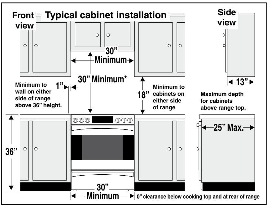
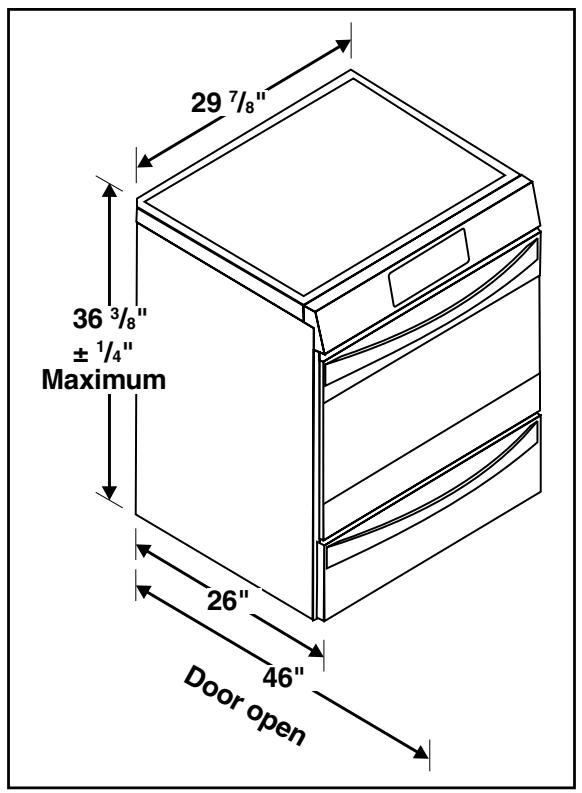
- 30" minimum clearance between the top of the cooking surface and the bottom of an unprotected wood or metal cabinet; or 24 " minimum when bottom of wood or metal cabinet is protected by not less than 14 " flame retardant millboard covered with not less than no. 28 MSG sheet steel, 0.015" stainless steel, 0.024" aluminum or 0.020" copper. The minimum clearance is 0" for the rear of the range. Follow all dimension requirements provided above to prevent property damage, potential fire hazard, and incorrect countertop and cabinet cuts.
Avoid locating cabinet storage space above the surface units to eliminate the possibility of cabinets catching on fire, or personal burns from reaching for the cabinets over the heated units. If cabinet storage is to be provided, risk can be reduced by installing a range hood that projects horizontally a minimum of 5'' beyond the bottom of the cabinets.
30" ELECTRIC RANGE INSTALLATION INSTRUCTIONS
2. Tools You Will Need
For leveling legs and Anti-Tip Bracket:
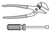
- Adjustable wrench or channel lock pliers
- 5/16" Nutdriver or Flat Head Screwdriver
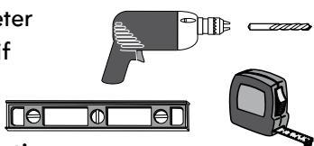
Electric Drill & 1/8" Diameter Drill Bit (Masonry Drill Bit if installing in concrete) - Level & Measuring Tape
For electrical supply connection:
1/4" & 3/8" Socket driver or Nutdriver
Additional Materials You Will Need:
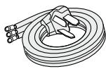
Power Supply Cord or
Copper Electrical Wiring & Metal Conduit (for hard wiring)
3. Anti-tip Bracket Installation Instructions
Important Safety Warning
To reduce the risk of tipping of the range, the range must be secured to the floor by the properly installed anti-tip bracket and screws packed with the range. Failure to install the anti-tip bracket will allow the range to tip over if excessive weight is placed on an open door or if child climbs upon it. Serious injury might result from spilled hot liquids or from the range itself.
If range is ever moved to a different location, the anti-tip brackets must also be moved and installed with the range.
Instructions are provided for installation in wood or cement floor. When fastening to floor, be sure that screws do not penetrate electrical wiring or plumbing.
WARNING Tip Over Hazard
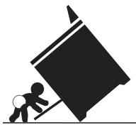
- A child or adult can tip the range and be killed.
-
Verify the anti-tip device has been installed to floor or wall as per installation instructions.
-
Ensure the anti-tip device is re-engaged to floor or wall when the range is moved.
- Do not operate the range without the anti-tip device in place and engaged.
- Failure to follow these instructions can result in death or serious burns to children and adults.

Range Leveling Leg
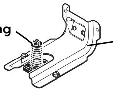
Anti-Tip Bracket
To check if the anti-tip bracket is installed properly, use both arms and grasp the rear edge of range back. Carefully attempt to tilt range forward. When properly installed, the range should not tilt forward.
A. Locate the Bracket Using the Template - Locate the bracket position (right or left side) by placing the template symmetrically to the center of the final range position. Mark the location of the screw holes, shown on template.

Figure 1
30" ELECTRIC RANGE INSTALLATION INSTRUCTIONS
B. Drill Pilot Holes and Fasten Bracket - Drill a 1/8" pilot hole where screws are to be located. If bracket is to be mounted to the wall, drill pilot hole at an approximate 20^ downward angle. If bracket is to be mounted to masonry or ceramic floors, drill a 3/16" pilot hole 1-3/4" deep. The screws provided may be used in wood or concrete material. Use a 5/16" nut-driver or flat head screwdriver to secure the bracket in place.
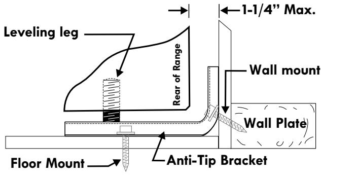
FASTEN BRACKET (WALL OR FLOOR MOUNTING)
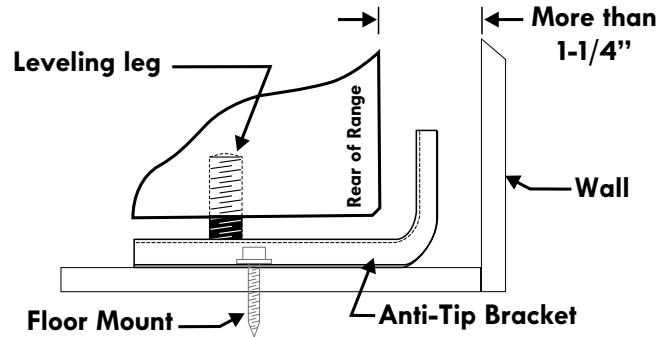
FASTEN BRACKET (FLOOR MOUNTING ONLY)
Figure 2
C. Level and position the range - Slide range to its final position. Insert the range leveling leg in the anti-tip bracket. Visually verify if the anti-tip bracket is engaged. Lower the range by adjusting the 4 leveling legs alternatively until the range is level. Check if the range is level by placing a spirit level on the oven rack. Take 2 readings with the spirit level placed diagonally; take a reading in one direction and then in the other direction. Level the range if necessary by adjusting the leveling legs.
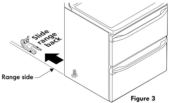
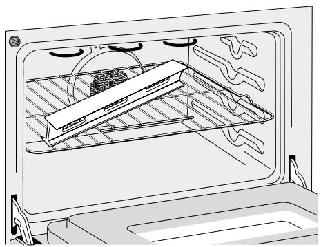
Figure 4
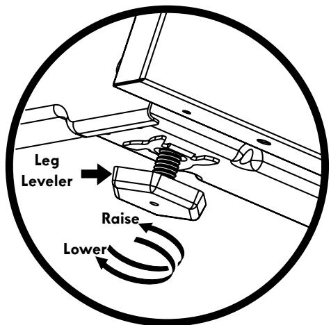
Figure 5
4. Serial Plate Information
The serial plate is located as shown. See the serial plate for the following information:
A. Model, lot and serial number of range.
B. Kilowatt rating (power requirements).
C. Voltage ratings.
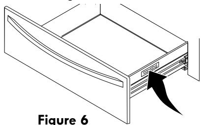
Figure 6
5. Electrical Connection Requirements (Canada only)
Plug the range cable (4 conductors) into a 4 conductor range outlet. Outlet must be properly grounded and in accordance with the Canadian Electrical Code (CSA Standard (C22.1 Part 1 - latest edition)- and any local electrical code requirements.
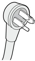
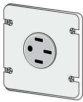
Canada Style Figure 7A
5.1 Electrical Connection Requirements (U.S.A. only)
This appliance must be properly installed and grounded by a qualified technician in accordance with the National Electrical Code ANSI/NFPA No. 70-latest edition- and local electrical code requirements.
This appliance may be connected by means of permanent "Hard Wiring" or "Power Supply Cord Kit." When hard wiring, do not leave excess wire in range compartment. Excess wire in the range compartment may not allow the access cover to be replaced properly, and could create a potential electrical hazard if wires become pinched. When using flexible conduit or range cable, use flex connector or range cable strain relief.
NOTE: Only use copper wire in connection to terminal block.
5.2 Models Requiring Power Supply Cord Kit
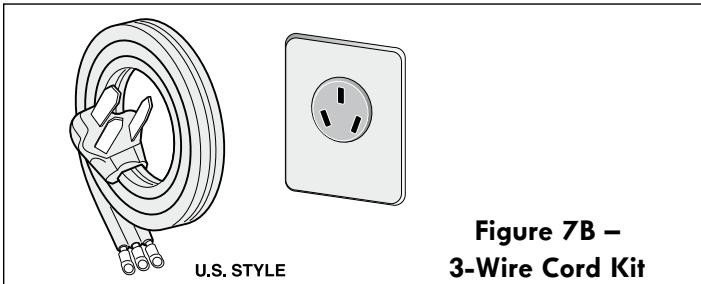
The user is responsible for connecting the power supply cord to the connection block located behind the back panel access cover.
This appliance may be connected by means of permanent "hard wiring"; flexible armored or nonmetallic shielded copper cable (when local code allow it) or by means of a power supply cord kit.
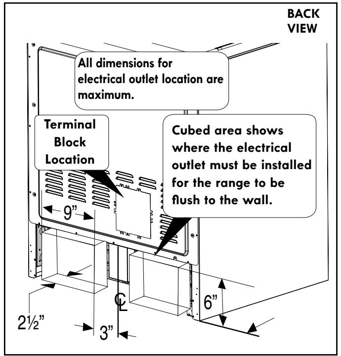
NOTE: Electric slide-in range is shipped from factory with 118 (2.9 cm) dia. hole as shown on figure 9. If a larger hole is required, punch out the knockout.
WARNING Risk of fire or electrical shock exists if an incorrect size range cord kit is used, the Installation Instructions are not followed, or the strain relief bracket is discarded.
For mobile homes, new installation or recreational vehicles, use only a power cord kit design for a range at 125V /250V 50A recommended (minimum 40A). Cord must have either 3 (when local code permits grounding through neutral) or 4 conductors. Terminal on end of wires must be either closed loop or open spade lug with upturned ends. Cord must have strain-relief clamp. If a 50A circuit is used, a 50A power cord must be used.
CAUTION Do not loosen the nuts which secure the factory-installed range wiring to terminal block while connecting range. Electrical failure or loss of electrical connection may occur.
WARNING
Electrical Shock Hazard
- Electrical ground is required on this appliance.
- Do not connect to the electrical supply until appliance is permanently grounded.
- Disconnect power to the circuit breaker or fuse box before making the electrical connection.
- This appliance must be connected to a grounded, metallic, permanent wiring system, or a grounding connector should be connected to the grounding terminal or wire lead on the appliance.
Failure to do any of the above could result in a fire, personal injury or electrical shock.
WARNING This appliance is manufactured with the frame grounded by connection of a grounding strap between the neutral power supply terminal and the frame. If used in USA, in a new branch circuit installation (1996 NEC), mobile home or recreational vehicle, where local code do not permit grounding through neutral (white) wire or in Canada; remove the grounding strap from the frame and cut the other end, near the neutral terminal. Connect the appliance in usual manner.
Three Conductor Wire Connection to Range
If local codes permit connection of the frame grounding conductor to the neutral wire of the copper power supply cord (see Figure 8):
- Remove the screws from the access plate at the lower right end of the rear cover to expose range terminal connection block.
-
Using the nuts supplied in the literature package, connect the neutral of the copper power supply cord to the center silver-colored terminal of the terminal block, and connect the other wires to the outer terminals. Match wires and terminals by color (red wires connected to the right terminal, black wires connected to the left terminal) (see Figure 8).
-
Replace the terminal cover and replace the
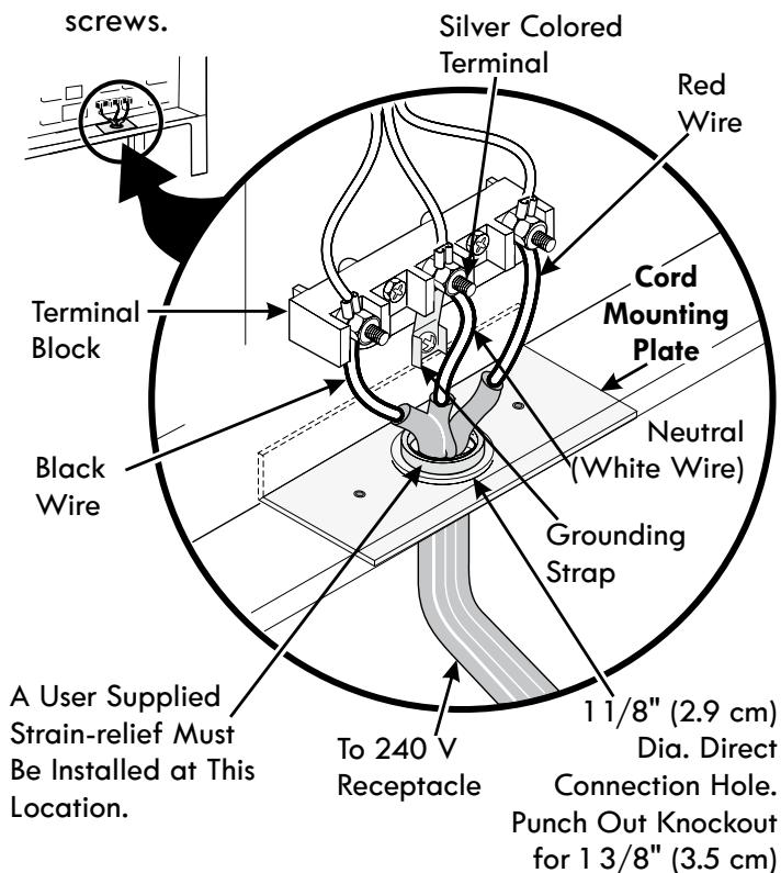
Figure 8
Four Conductor Wire Connection to Range
Where local codes does NOT permit connection of the frame grounding conductor to the neutral wire of the copper power supply cord (see Figure 9):
- Remove the screws from the access plate at the lower right end of the rear cover to expose range terminal connection block.
- Remove the grounding strap from the terminal block and from the appliance frame.
- Using the nuts supplied with the literature package, connect the ground wire (green) of the copper power supply cord to the frame of the appliance with the ground screw, using the hole in the frame where the ground strap was removed (see Figure 9).
- Connect the neutral of the copper power supply cord to the center silver-colored terminal of the terminal block, and connect the other wires to the outer terminals. Match wires and terminals by color (red wires connected to the right terminal, black wires connected to the left terminal).
- Replace the terminal cover and replace the screws.
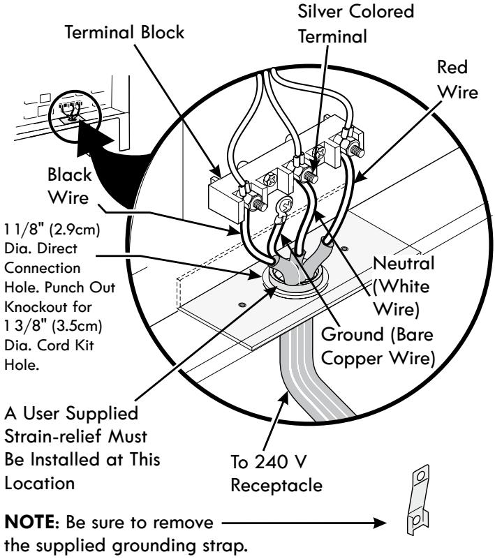
Figure 9
Direct Electrical Connection to the Circuit Breaker, Fuse Box or Junction Box
If the appliance is connected directly to the circuit breaker, fuse box or junction box, use flexible, armored or nonmetallic sheathed copper cable (with grounding wire). Supply a U.L. listed strain-relief at each end of the cable. At the appliance end, the cable goes through the Direct Connection Hole (see Figure 9) on the Cord Mounting Plate. Wire sizes (copper wire only) and connections must conform to the rating of the appliance. Where local codes permit connecting the appliance-grounding conductor to the neutral (white) wire (see Figure 10):
- Be sure that no power is supplied on the cable from residence.
- Follow instructions on previous page for Four Conductor Wire Connection to Range (Fig. 9).
- In the circuit breaker, fuse box or junction box (Fig. 10):
a) Connect the green (or bare copper) wire, the white appliance cable wire, and the neutral (white) wire together.
b) Connect the 2 black wires together.
c) Connect the 2 red wires together.
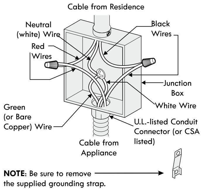
Figure 10 3-Wire (Grounded Neutral) Electrical System (Example: Junction Box)
Where local codes DO NOT permit connecting the appliance-grounding conductor to the neutral (white) wire, or if connecting to 4-wire electrical system (see Figure 11):
- Be sure that no power is supplied on the cable from residence.
- Follow instructions on previous page for Four Conductor Wire Connection to Range (Fig. 9).
- In the circuit breaker, fuse box or junction box (Fig. 11):
a) Connect the white appliance cable wire to the neutral (white) wire.
b) Connect the 2 black wires together.
c) Connect the 2 red wires together.
d) Connect the green (or bare copper) grounding wire to the grounding wire of the circuit breaker, fuse box or junction box.
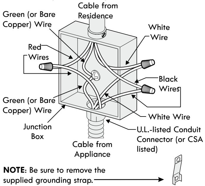
Figure 11 4-Wire Electrical System (Example: Junction Box)
6. Checking Operation
Refer to the Use and Care Guide for operation.
CAUTION Do not touch cooktop glass or elements. They may be hot enough to burn you.
Before You Call for Service
Read the Before You Call for Service Checklist and operating instructions in your Use and Care Guide. It may save you time and expense. The list includes common occurrences that are not the result of defective workmanship or materials in this appliance.
Refer to your Use and Care Guide for Sears service phone numbers, or call 1-800-4-MY-HOME®.
NOTES
Support anti-bascule