
MIRROR - Mirror FABER - Free user manual and instructions
Find the device manual for free MIRROR FABER in PDF.
| Product Type | Range Hood |
| Brand | FABER |
| Model | MIRROR |
| Dimensions (W x D x H) | 900 x 500 x 200 mm (estimated) |
| Weight | 15 kg (estimated) |
| Power Supply | 220-240 V ~ 50 Hz |
| Motor Power | 150 W (estimated) |
| Lighting | Integrated LED, adjustable brightness |
| Speeds | 4 speeds + intensive (timed 10 min) + 24H (10 min/h) |
| Main Functions | Motorized panel opening/closing, remote control, 30 min delay timer, filter saturation alarm |
| Maintenance and Cleaning | Dishwasher-safe metal grease filters; replaceable activated carbon filters every 4 months |
| Safety | Automatic stop in case of obstacle during opening/closing, backdraft protection |
| Spare Parts and Repairability | Grease and carbon filters, LED bulbs, remote control (CR2032 battery), fuse |
| General Information | Class I, mandatory grounding; minimum distance to cooking surface: 650 mm (gas: 650 mm or more) |
Frequently Asked Questions - MIRROR FABER
User questions about MIRROR FABER
0 question about this device. Answer the ones you know or ask your own.
Ask a new question about this device
Download the instructions for your Mirror in PDF format for free! Find your manual MIRROR - FABER and take your electronic device back in hand. On this page are published all the documents necessary for the use of your device. MIRROR by FABER.
USER MANUAL MIRROR FABER
CARE AND CLEANING 14
SOMMAIRE
FR
CONSIGNES DE SECURITE 16
CHARACTERISTIQUES 19
INSTALLATION 21
UTILISATION 24
NETTOYAGE ET ENTRETIEN 26
INHALTSVERZEICHNIS
DE
For your safety and correct operation of the appliance, read this manual carefully before installation and use. Always keep these instructions with the appliance even if you move or sell it. Users must fully know the operation and safety features of the appliance.
The wire connection has to be done by specialized technician.
- The manufacturer will not be held liable for any damages resulting from incorrect or improper installation.
- The minimum safety distance between the cooker top and the extractor hood is 650~mm (some models can be installed at a lower height, please refer to the paragraphs on working dimensions and installation).
- If the instructions for installation for the gas hob specify a greater distance, this must be respected.
- Check that the mains voltage corresponds to that indicated on the rating plate fixed to the inside of the hood.
- Means for disconnection must be incorporated in the fixed wiring in accordance with the wiring rules.
- For Class I appliances, check that the domestic power supply guarantees adequate earthing.
- Connect the extractor to the exhaust flue through a pipe of minimum diameter 120mm . The route of the flue must be as short as possible.
- Regulations concerning the discharge of air have to be fulfilled.
- Do not connect the extractor hood to exhaust ducts carrying combustion fumes (boilers, fireplaces, etc.).
- If the extractor is used in conjunction with non-electrical appliances (e.g. gas burning appliances), a sufficient degree of aeration must be guaranteed in the room in order to prevent the backflow of exhaust gas. When the cooker hood is used in conjunction with appliances supplied with energy other than electric, the negative pressure in the room must not exceed 0,04 mbar to prevent fumes being drawn back into the room by the cooker hood.
- The air must not be discharged into a flue that is used for exhausting fumes from appliances burning gas or other fuels.
- If the supply cord is damaged, it must be replaced from the manufacturer or its service agent.
- Connect the plug to a socket complying with current regulations, located in an accessible place.
- With regards to the technical and safety measures to be adopted for fume discharging it is important to closely follow the regulations provided by the local authorities.
WARNING: Before installing the Hood, remove the protective films.
- Use only screws and small parts in support of the hood.
WARNING: Failure to install the screws or fixing device in accordance with these instructions may result in electrical hazards.
- Do not look directly at the light through optical devices (binoculars, magnifying glasses...).
- Do not flambé under the range hood; risk of fire.
- This appliance can be used by children aged from 8 years and above and persons with reduced physical, sensory or mental capabilities or lack of experience and knowledge if they have been given supervision or instruction concerning use of the appliance in a safe way and understand the hazards involved. Children shall not play with the appliance. Cleaning and user maintenance shall not be made by children without supervision.
- Children should be supervised to ensure that they do not play with the appliance.
- The appliance is not to be used by persons (including children) with reduced physical, sensory or mental capabilities, or lack of experience and knowledge, unless they have been given supervision or instruction.
Accessible parts may become hot when used with cooking appliances. - Clean and/or replace the Filters after the specified time period (Fire hazard). See paragraph Care and Cleaning.
- There shall be adequate ventilation of the room when the range hood is used at the same time as appliances burning gas or other fuels (not applicable to appliances that only discharge the air back into the room).
- The symbol on the product or on its packaging indicates that this product may not be treated as household waste. Instead it shall be handed over to the applicable collection point for the recycling of electrical and electronic equipment. By ensuring this product is disposed of correctly, you will help prevent potential negative consequences for the environment and human health, which could otherwise be caused by inappropriate waste handling of this product. For more detailed information about recycling of this product, please contact your local city office, your household waste disposal service or the shop where you purchased the product.
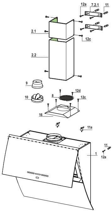
Components
| Ref. | Q.ty | Product components |
| 1 | 1 | Cooker hood with control unit, lights, blower unit, filters |
| 2.1 | 1 | Upper chimney |
| 2.2 | 1 | Lower chimney |
| 8 | 1 | Air outlet grid |
| 9 | 1 | Reducer flange Ø 150-120 |
| 10 | 1 | Damper (Optional) |
| 16 | 1 | Cover for recycling version |
| Ref. | Q.ty | Installation components |
| 7.2.1 | 2 | Fixing brackets for upper chimney |
| 11 | 5 | Plugs |
| 11a | 2 | Plugs SB 12/10 |
| 12a | 5 | Screws 4,2 x 44,4 |
| 12c | 10 | Screws 2,9 x 6,5 |
| 12e | 2 | Screws 2,9 x 9,5 |
| Q.ty | Documentation | |
| 1 | Instruction booklet | |

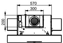
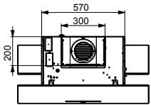
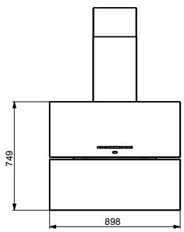
The dimensions depend on the chosen version
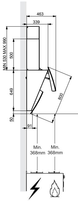


Wall drilling and bracket fixing
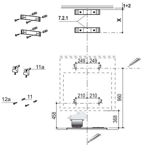
As a first step, proceed with the following drawings:
- a vertical line up to the ceiling or up to the upper limit, at the centre of the area in which the hood is to be fitted;
- a horizontal line at a minimum 960mm above the cooker top.
- Mark a point (1) on the horizontal line, 249 mm to the right of the vertical reference line.
- Repeat this operation on the other side, checking that the two marks are levelled.
- Mark a reference point (2) as indicated at 210 mm from the vertical reference line and 458 mm above the cooker top.
- Repeat this operation on the other side, checking that the two marks are levelled.
- Drill at the marked points (1), using a 12mm drill bit.
- Drill at the marked point (2), using a 8mm drill bit.
- Insert the bracket plugs 11a into the holes (1) and tighten the screws.
- Insert plug 11 into hole (2).
- Place bracket 7.2.1 on the wall, about 1 - 2mm from the ceiling or from the upper limit, aligning the centre (notch) with the vertical reference line.
- Mark the wall at the centres of the bracket holes.
- Place the bracket 7.2.1 on the wall at X mm below the first bracket ( X = height of the upper chimney section), aligning the centre (notch) with the vertical line.
- Mark the wall at the centres of the bracket holes.
- Drill 8mm holes at all the marked centre points.
- Insert the wall plugs 11 in the holes.
Fix the brackets using the 12a screws (4,2× 44,4) supplied with the hood.
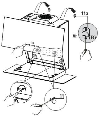
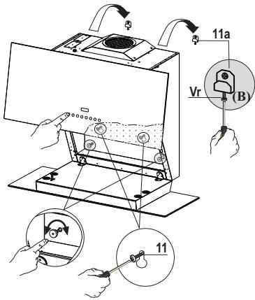
Fitting the Hood canopy
- Adjust the two screws Vr , in the brackets 11a, so that they are at start of their travel (B).
- Hook the hood body to the two brackets 11a.
- Connect the Hood to the Mains Power Supply, inserting a bip switch with a contact aperture of at least 3mm .
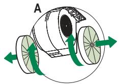
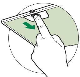
- Open the top panel. (See the paragraph on USE)
- Open the Bottom Door by pulling it downwards with your hands
- Remove the Metal Grease Filters using the handles provided.
- From the inside of the hood body, turn screws Vr to level the h body itself.
Warning: should the rear wall not be completely flat and can the two glass panels not to be aligned, pls turn on the two knob the lower part inside the hood body until you reach the per alignment of the two glass panels.
- Fasten the safety screw 11.
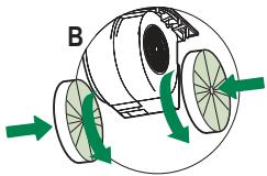
- Replace the Metal Grease Filters, then shut the top panel. (See paragraph on USE)
- Disconnect the hood from the mains power supply.
Warning: Should the door encounter an obstacle while open or closing it will block. When the obstacle is removed and button is pressed again the door will open.
Warning: In the event of a malfunction, check the fuse.
Replacing the fuser
- The fuser is placed up on the left side. Turn the fuser holder indicated. Replace the fuser with one having the same features.
Connections
DUCTED VERSION AIR EXHAUST SYSTEM
When installing the ducted version, connect the hood to the chim using either a flexible or rigid pipe 150 or 120mm , the choice which is left to the installer.
To install a 150 pipe
- To install the dumper 10
Fix the pipe in position using sufficient pipe clamps (not s plied).
To install a 120 pipe
- To install a 120mm air exhaust connection, insert the reduu flange 9 on the dumper 10.
Fix the pipe in position using sufficient pipe clamps (not s plied). - Remove any activated charcoal filters.
cer
To install the hood in recycling version, the optional charcoal filter kit must be purchased.
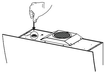
- Remove the chimney angle bracket.
- Screw the filter cover onto the air outlet, using four screws 12c (2.9 x 12.5).
Fix the air outlet grid 8 on the recirculation air outlet using the 2 screws 12d (2,9 x 9,5) provided.


ELECTRICAL CONNECTION
- Connect the hood to the mains supply.
- Open the upper panel by pressing the A-key (See Part "USE") for at least 2 seconds.
- Remove the metal filters (See Part "MAINTENANCE") and make sure that the connector piece of the supply cable is correctly inside the hood socket.
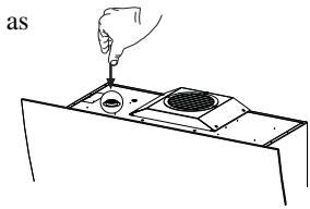
Chimney assembly
Upper exhaust Chimney
- Slightly widen the two sides of the upper chimney and hook them behind the brackets 7.2.1, making sure that they are well seated.
- Secure the sides to the brackets using the 4 screws 12c (2,9 x 9,5) supplied.
Lower exhaust Chimney
- Slightly widen the two sides of the chimney and hook them between the upper chimney and the wall, making sure that they are well seated.
Fix the lower part laterally to the hood body using the 2 screws 12c (2,9 x 9,5) supplied.
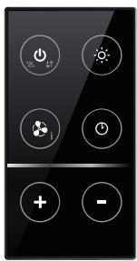
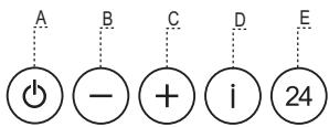
Control panel
| Button | Function | Display |
| A | Door Closed: Press and hold for approximately 2 Seconds to open the door and turn the motor on at the last speed set. Door Open: Press briefly to turn the motor Off or On. | Displays the set speed. |
| B | Decreases the working speed. | The number of lighted segments decreases. |
| C | Increases the working speed. | The number of lighted segments increases. |
| D | Activates/Deactivates Intensive speed. This speed is timed to run for 10 minutes. At the end of this time the system will automatically return to the speed set before. Suitable to deal with maximum levels of cooking fumes. Cannot be activated when in 24H mode. | The indicator I flashes and all the segments on the Display are lit. |
| Press and hold the button for approximately 5 seconds, with all the loads turned off (Motor and Lights) and no alarms in progress, to turn the Activated Charcoal Filter Alarm On / Off. | Button "C" flashes twice - Alarm On. Button "C" flashes once - Alarm Off. | |
| E | Activates/Deactivates 24H speed. This starts the motor at a speed that allows suction of 100 m3/h for 10 minutes every hour. This mode cannot be activated if Intensive or Delay modes are active. | Displays 24 and the segments on the Display light up in cycle. |
| Press and hold the button for approximately 5 seconds, with all the loads turned off (Motor and Lights) and no alarms triggered, to turn the Remote control On / Off. | (Motor LED bar flashes twice) - Remote control On. (Motor LED bar flashes once) - Remote control Off. | |
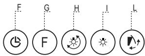
| F | Activate / Deactivate Delay. Can be activated with motor on (except for Intensive and 24H mode). Activates automatic shutdown of the Motor and the Lighting with a 30' delay. | Displays a Clock symbol. |
| Press and hold for 5 Seconds to Activate / Deactivate Lock Keyboard mode for example in order to clean the Glass. | The Leds light up and run a start-up sequence. | |
| G | Performs a Reset of the Filter saturation alarm when the button is pressed for approximately 3 seconds when all the users (motor + lights) are turned off | After 100 hours in operation the Drop symbol is displayed to indicate saturation of the Metal Grease Filters. After 200 hours in operation the letter C is displayed to indicate saturation of the Activated Charcoal filters. |
| H | Modifies the intensity of the Lighting each time the Button is pressed, in cycle. | - |
| I | Door Closed: When pressed and held for approximately 2 seconds opens the door half way and turns the lighting on to maximum intensity. The intensity can be modified using button H. - When the button is pressed again, the lighting turns off and the door closes. - When button A is pressed, the Lights turn off and the motor only works at the first two speeds. Door Open: Press briefly to turn the lighting On or Off. | - |
| L | Door Closed: Press and hold for approximately 2 Seconds to open the door, turn the motor on at speed three and turn the lighting on at maximum intensity. Door Open: When pressed and held for approximately 2 seconds turns off the motor and the lighting, cancelling any function that may be active and closing the door. | - |
Warning:
During the Opening and Closing phase the panel has a guard device that reverses the direction of movement in the event of blockage during the movement itself. It performs a maximum of 6 attempts before the “ ” icon flashes to indicate actual blockage. At this point, remove the obstacle preventing movement if possible, then press and hold button L for 2 seconds. The panel will once again make a maximum of 6 attempts to close or open before reverting to blocked status if movement is not successful. In this case it will be necessary to call the Technical Service Department.
REMOTE CONTROL
This appliance can be commanded using a remote control, powered by a CR2032 type 3 V battery (not supplied).
- Do not place the remote control near heat sources.
- Do not discard the batteries with normal waste, they must be put into the specific containers.
Remote control panel
| Motor | Door Closed: Opens the door and turns the motor on at the last speed set. | |
| Door Open: Motor On / Off | ||
| Pressed for 2 Seconds: a) If the door is open, Motor + Lights Off. b) If the door is closed, Opens the door and Lights + Motor On. | ||
| - | - | |
| - | - | |
| Light | Door Closed: Opens the door half way and turns the Lights on a Maxi- mum Intensity. | |
| Door open half way: Turns lights off and closes the door. | ||
| Door Open: Lights On / Off. | ||
| Intensive | Activates the Intensive function. | |
| Delay | Activates the Delay function. | |
| Pressed for 2 Seconds: Activates / Deactivates the 24H function. | ||
| - | Increases the working speed each time it is pressed. | |
| - | Decreases the working speed each time it is pressed. | |
Metal grease filters
Filters can be washed in the dish machine. They need to be washed when Drop-sign appears on the display or in any case every 2 months, or even more frequently in case of particularly intensive use of the hood.
Alarm reset
- Press the G-key for at least 2 seconds.
Cleaning the filters
- Open the upper panel by pressing the A-key for 1 second (see Part USE).
- Open the Bottom Door by pulling it downwards with your hands.
- Remove the filters one by one pushing them towards the back side of the hood unit and simultaneously pulling downwards.
- Any kind of bending of the filters has to be avoided when washing them. Before fitting them again into the hood make sure that they are completely dry. (The colour of the filter surface may change throughout the time but this has no influence to the filter efficiency).
- When fitting the filters into the hood pay attention that they are mounted in correct position the handle facing outwards.

This cannot be washed or regenerated, and must be changed when the C symbol on the display appears, or at least once every 4 months. The Alarm signal must be activated in advance.
Activating the alarm signal
- In Recirculation Version Hoods, the Filter Saturation Alarm must be activated on installation or at a later date.
- Turn the Lights and the Suction Motor off.
-
Press and hold button D for approximately 5 seconds to enable / disable the A.C. Filters
-
Symbol C flashes twice, A.C. Filter saturation alarm ACTIVATED
- Symbol C flashes once, A.C. Filter Saturation alarm DEACTIVATED
REPLACING THE CHARCOAL FILTER
Alarm reset
- Press the G-key for at least 2 seconds.
Replacing the filter
- Open the upper panel by pressing the A-key for about a second (see Part USE).
- Remove the metal filters.
- Remove the saturated charcoal filter as indicated (A).
- Fit the new filters as indicated (B).
- Put the metal grease filters in their seats.
Lighting unit
- For replacement contact technical support ("To purchase contact technical support").
i
REEMPLACEMENT DU FILTRE ANTI-ODEUR AU CHARBON ACTIF
Ia6apntHbIe pa3MepbI MeHIOCTB 3aBNCIMOcN O T BbIbpaHHo MoEIN np60pa

CbepeHne OTBepCTn B CteHe n KpePneHne cko6
Побети Ha CTeHe:
- BepTHKaJIbHyIO JINHHIO IO IIOTOJIka HJIN IO BepXHeRo IpeIeJa IO IeHTpy yUacTKa, IpeIHa3HaueHHO rJIA yCTaHOBKN BbITgKKN;
- TOPIN3OHTaJIbHyIO JINHHIO Ha BBICOTE He MeHee 960 MM OT BapOuHOI NaHeJIN.
Cipaba OST6a3OBoB BepTHKaJIbHOH JInHHn Ha paCCToHNN 249 MM OT Hee,OTMeHTb Ha roPH3OHtAJbHOH JInHHn TOyKy (1). - IIOBtopHTb 3Ty OIepaIIOU c IpiOTHBONIOJKeHHoI CTOpHO bI BepTHKaJIbHOJ JINHHN H IpiOBepHTb, YTO6bI TOUKH 6blHN Ha ODNOM yPOBHe.
AHaJIIOHnHbIM CIIIOcO6OM OTMeHTNb 6a3OByIO TOky (2) Ha paCCTo8HHN 210 MM OT BepTHKaJIbHOJINHHN H a BbICote 458 MM OT BapOuHOH IaHeJIH. - IIOBTOPHTb 3Ty OIepaIHHO C IIPOTHBOIIOJIOKeHHO CTOpOHb BEpTHKaJIbHOJIIHHN H IIpOBepHTb, YTO6bI TOUKN 6blIN Ha OJHOM yPOBHe.
- BbICBepJIINb OTBepCTnA 0 12 MM B O6O3HaueHHbIX TOUkAX (1).
- BbICBepJIHTb OTBepCTHЯ 8 MM B O6O3HaueHHbIX TOUkax (2).
BCTaBHTbIIO6eJIHcoCKO60n11aBOTBepCTHg(1)H3ATaHYb BHTbl.
BCTaBHTIIO6eJIb11B(2). - IIpnIOKHTb cKO6y 7.2.1 K cTeHe Ha paCCToHnn 1-2 MM OT ITOJka HIn BEpxHrO IpeJeJa H BbIpOBHrTb ee IeHTp (Pi3bl) IIO BEPTHKaJIbHoJ JInHHn.
- OTMeTHTb Ha CTeHe IeHTpaJIbHyIO TOuKy OTBepCTHn cKO6bl.
- IIpnIOKHTb cKO6y 7.2.1 K cTeHe Ha paCCTOaHHN X MM OT IpeIbIyIeH cKO6b (X = BbICota BepxHe YacTH NbIMOXoJa) H bIpOBHrTb ee IeHTp (Pi3bI) IIO BepTKaJIbHOJ LHHn.
- OTMeTnTb Ha cTeHe IeHTpaJIbHyIO TOUky OTBepCTH NCKo6bl.
- BbICBepJIHTb OTBepCTHЯ 08MM B O6O3HaueHHbIX TOUkax.
BCTaBHTIIO6eJIIN11BCOOTBeTCTBYIOIIHNEOTBepCTHIA.
3aKpeIINb cKO6bI c IOMOIIbIO BVHTOB 12a (4,2 x 44,4), IOCTaJIeMbIX B KOMIIJIeKTe C H3JIeJIHem.
BCTaBBTe IBA BHNTa Vr KPOHITeHOB 11a B HCXOJHOe IOJIIOKeHHe (B).
-ПовесьтЕ КОпИС ВБТЯЖКНа 2КрОнштЕна 11a.
CoeINHHTe BbITKky c cETbIO IINTaHHI; JIJI 3TOIg yCTaHOBHTe DBYXIIIOJIOCHbI BbIKJIIOHaTeJIb C MHHImaJIbHbIM pa3BeJeHHEM KOHTAKTOB 3 MM.
- OTKpoIte BepXHIOIO IaHeJIb. (CM. pa3JIeJ 3KCIJIYATAUINIA)
- OTKpoIte HnKHHIOI KpbIIky, IIOrHyB ee pyKaMn BnH3
3a cIeuaJIbHbIe pyuKN BbIbTe JnHOBbIe IJIbTpbl.
- H3Hytpn KOpHpyBaBtJHKN OTpeRyJIHpIyTe 3aTJKKy BnHTOB Vr, YTO6bblBCTABNTb erO II yPoBHIO.
BHHMaHHe: EcII HEPOBHaa IOBepXHOCTb CteHb He IIO3BOJIaETIpaBILbHO BbIPOBHaTb IOTpeyIINPOBaTb IIOJOKeHNIECTeKJIHHbIX NaheJeI, Heo6xoJIMO IIOJKpyTHTbpeYJIINPOOCHHe pbluAaKKn, HaxOJaIeCeH BHyTpri KOpIYCaBBtIaKKn B HnKHeJ qactn
3aTnHTe IpeoXpaHHTeJIbHbI BnHT 11.
- IocTaBbTe Ha meCto JnHpOBBeI HJbTpbl N BepXHIO IaHeJI. (CM. pa3JeI KCIJIYATAUIIIN)
- OtcoeHnHTe BbITgKky OT cETH 3JIeKtpoINHTaHnI.
BhImaHne: EcIn BO BpEm paKpbTnI INI 3akpbTnI KpbIka BCTpeaet npenrTCTBne, OHa OCTaHabNIBaETc; nocne ydaJIeHn npenrTCTBn I NOBtOpHOrO HaxKaTHN KJAbuIi N KpbIka OTKpbIbaETc.
BHHMaHHe: B cIyae HeuCnpaBHOCTn IpoBepbTe COCTOHNIE npedoxpaHHTeJI.
3aMeHa npedeoxpaHnteJia
- IIpeIoXpaHHTeJIb HaxoIHTcB BEpxHy HaJIeBO; IIOBePHHTe, KaK IIOKa3aHO, IIJaBkyIO BCTaBky H 3aMeHHTe IIpeIoXpaHHTeJIb Ha HObI C TaKHMH JxE XapaKTEpHCTHKaMn.
CoeHHnHn
BbIpyCK BO3DyXA I3 BCAbIBAIOUeBbITJXKIN
PanaheIy npabJIeHnIa
| Коньka | Назачени | Ди�делей |
| A | Стбога зakрыга: пгн Нжатин Кнокип римерно на 2 секулд рожнховот otкьшане Стбоги и Всночьдные вларалд на сборoctин BCaslbahnig, Заданногп ргнпocлдем cityaeюлдьвлгжков.Стбога озрыга: пг краитом Нжатин Кнокип рожнховот bsklwochene hyнВсночьдные bдаггета. | Отошgesенze zadanhoшь сборoctин BCaslbahnig. |
| B | Снжichte SCOKOCTH BCASLBAHNIG. | Колчесгв BGKIOCHENHbIX сгмг�ю WMeHbIaETC. |
| C | Увileчente SCOKOCTH BCASLBAHNIG. | Колчесгв BGKIOCHENHbIX сгмг�ю WMeHbIaETC. |
| D | Всночen�ыьсночenne HnntchenhBnrope pezhma. Работа вьлськьи BНненснIHOM peshmte orpanghena 10 mHytamn. Ппснчeteшип Злго Всмгпссma NaHnnaeet chobla pabotat na Hsckoctn, Заданногп parache. ИнненснIHbI peshmпрдянathaydлду ChyBaev cheyb. Бolyногп obshma pyriппг�otobleni.Злго peshm HeJIOCTUHN, ссiln BkLWHeHPEPZM 24H. | Могает CTMHBOI I, И на ддддддддддддддддддддддддддддддддддддддддддддддддддддддддддддддддддддддддддддддддддддддддддддддддддддд徳. |
| Нжатим Кнокип римерно на 5 секулд, Когд BCgHpyrachny OIKLOHOTY (Дыгател N ocbeuichne), bblnoJIHTETcB KcHouHne/otlcKNoHne CHngHuaHIN HacbIeH yToIbIbHxФИbIbTPO. | Симьо CB Mнгг.Tpr3a: cngHnHnBaIIHn HacbIeHn YOttlbHxФИbIbTPO BcKIOHNe.Симьо CB Mнгг.Tpr3a: cngHnHnBaIIHn HacbIeHn YOttlbHxФИbIbTPO BcKIOHNe.Симьо CB Mнгг.Tpr3a: cngHnHnBaIIHn HacbIeHn YOttlbHxФИbIbTPO BcKIOHOH. | |
| E | Всночen�ыьсночenne pezhma 24H. Пгн ВсночьнHom peshme 24H Dыгатatel BcKIOHaTe CakKbIчас no 10 mHytH na Hsckoctn,обсчteчнauhoцel BcAslbAHnne 100 m34. Ⓞтгр.Kнннннн HDcKIOStyHn, ссiln BcKIOHn HnHtchenhBI nOcKIOHn DcKIOStyHn, ссiln BcKIOHn HnHtchenhBI nOcKIOStyHn DcKIOStyHn DcKIOStyHn DcKIOStyHn DcKIOStyHn DcKIOStyHn DcKIOStyHn DcKIOStyHn DcKIOStyHn DcKIOStyHn DcKIOStyHn DcKIOStyHn DcKIOStyHn DcKIOSTyHn DcKIOStyHn DcKIOStyHn DcKIOStyHn DcKIOStyHn DcKIOStyHn DcKIOStyHn DcKIOStyHn DcKIOStyHn DcKIOStyHn DcKIOStyHn DcKIOStyHn DcKIOStyHn | Отошgesенze wICHA "24"; ZNKнннннгсь BGKIOHNe cergentoh. |
| Пгн Нжатим Кнокип римерно на 5 секулд, Когд BCgHpyrachny OTlcKIOHOTY (Дыгател N ocbeuichne) nOcKITCTHYOT ABAPRhybne BcKIOStyHn OcKIOStyHn DcKIOStyHn DcKIOStyHn DcKIOStyHn DcKIOStyHn DcKIOStyHn DcKIOStyHn DcKIOStyHn DcKIOStyHn DcKIOStyHn DcKIOStyHn DcKIOStyHn DcKIO StyHn DcKIOStyHn DcKIOStyHn DcKIOStyHn DcKIOStyHn DcKIOStyHn DcKIOStyHn DcKIOStyHn DcKIOStyHn DcKIOStyHn DcKIOStyHn DcKIOStyHn DcKIOStyHn OcKIOStyHn DcKIOStyHn DcKIOStyHn DcKIOStyHn DcKIOStyHn DcKIOStyHn DcKIOStyHn DcKIOStyHn DcKIOStyHn DcKIOStyHn DcKIOStyHn DcKIOSTyHn DcKIOSTyHn DcKIOSTyHn DcKIOSTyHn DcKIOSTyHn DcKIOSTyHn DcKIOSTyHn DcKIOSTyHn DcKIOSTyHn DcKIOSTyHn DcKIOSTyHn DcKIOSTyHn DcKIOSTyHn OcKIOStyHn DcKIOSTyHn DcKIOSTyHn DcKIOSTyHn DcKIOSTyHn DcKIOSTyHn DcKIOSTyHn DcKIOSTyHn DcKIOSTyHn DcKIOSTyHn DcKIOSTyHn DcKIOSTyHn DcKIOOSTYHn DcKIOSTYHn DcKIOOSTYHn DcKIOOSTYHn DcKIOOSTYHn DcKIOOSTYHn DcKIOOSTYHn DcKIOOSTYHn DcKIOOSTYHn DcKIOOSTYHn DcKIOOSTYHn DcKIOOSTYHn DcKIOOSTYHn DcKIOOSTYHn DcKIOOSTYHn | 2MHNTANG CBeTNOIDH INKIAI JByDrATRE -pyIbT /IV akTbEN.1MHNTANG CBeTNOIDH INKIAI JByDrATRE -pyIbT /IV akTbEN. | |
| F | Всночen�ыьсночenne pykhimi phizycha 96.34.Ф.Д.Т.Ф.Ф.Ф.Ф.Ф.Ф.Ф.Ф.Ф.Ф.Ф.Ф.Ф.Ф.Ф.Ф.Ф.Ф.Ф.Ф.Ф.Ф.Ф.Ф.Ф.Ф.Ф.Ф.Ф.Ф.Ф.Ф.Ф.Ф.Ф.Ф.Ф.Ф.Ф.Ф.Ф.Ф.Ф.Ф.Ф.Ф.Ф.Ф.Ф.Ф.Φ.Ф.Ф.Ф.Ф.Ф.Ф.Ф.Ф.Ф.Ф.Ф.Ф.Ф.Ф.Ф.Ф.Ф.Ф.Ф.Ф.Ф.Ф.Ф.Ф.Ф.Ф.Ф.Ф.Ф.Ф.Ф.Ф.Ф.Ф.Ф.Ф.Ф.Ф.Ф.Ф.Ф.Ф.Ф.Ф.Ф.Ф.Ф.Ф.Ф.Б. | Отошgesенze chmboLoJaЧаOB. |
| Пгн Нжатим Кнокип римерно на 5 секулд, Когд BCgHpyrachny OTlcKIOHOTY (Дыгател N ocbeuichne) nOcKIOStyHn OcKIOStyHn DcKIOStyHn DcKIOStyHn DcKIOStyHn DcKIOStyHn DcKIOStyHn DcKIOStyHn DcKIOStyHn DcKIOStyHn DcKIOStyHn DcKIOStyHn DcKIOOSTYHn DcKIOSTYHn DcKIOOSTYHn DcKIOOSTYHn DcKIOOSTYHn DcKIOOSTYHn DcKIOOSTYHn DcKIOOSTYHn DcKIOOSTYHn DcKIOOSTYHn DcKIOOSTYHn DcKIOOSTYHn | ||
| Пгн Нжатим ⎠ггун PhizMeRno Na 5 секулд, рожнховп мсгггсь nOcKIOStyHn OcKIOStyHn DcKIOStyHn DcKIOStyHn DcKIOStyHn DcKIOStyHn DcKIOStyHn DcKIOStyHn DcKIOStyHn DcKIOStyHn DcKIOStyHn DcKIOStyHn DcCIOStyHn DcKIOStyHn DcKIOStyHn DcKIOStyHn DcKIOStyHn DcKIOStyHn DcKIOStyHn DcKIOStyHn DcKIOStyHn DcKIOStyHn DcKIOStyHn DcKIOStyHn DcKIOSty Hn DcKIOStyHn DcKIOStyHn DcKIOStyHn DcKIOStyHn DcKIOStyHn DcKIOStyHn DcKIOStyHn DcKIOStyHn DcKIOStyHn DcKIOStyHn DcKIOStyHn DcKIOStyHn DcCIOStyHn DcKIOSTyHn DcKIOSTyHn DcKIOSTyHn DcKIOSTyHn DcKIOSTyHn DcKIOSTyHn DcKIOSTyHn DcKIOSTyHn DcKIOSTyHn DcKIOSTyHn DcKIOSTyHn DcKIOSTy Hn DcKIOSTyHn DcKIOSTyHn DcKIOSTyHn DcKIOSTyHn DcKIOSTyHn DcKIOSTyHn DcKIOSTyHn DcKIOSTyHn DcKIOSTyHn DcKIOSTyHn DcKIOSTyHn DcKIOSTyHn DcCIOStyHn DcKIOSTyHn DcKIOSTyHn DcKIOSTyHn DcKIOSTyHn DcKIOSTyHn DcKIOSTyHn DcKIOSTyHn DcKIOSTyHn DcKIOSTyHn DcKIOSTyHn DcKIOSTyHn | ||
| G | Пгн Нжатим Кнокип римерно на 3 секулд, Когд BCgHpyrachny OTlcKIOHOTY (Дыгател N ocbeuichne) nOcKIOStyHn OcKIOStyHn DcKIOStyHn DcKIOStyHn DcKIOStyHn DcKIOStyHn DcKIOStyHn DcKIOSty Hn DcKIOStyHn DcKIOStyHn DcKIOStyHn DcKIOStyHn DcKIOStyHn DcKIOSTYHn DcKIOSTYHn DcKIOSTYHn DcKIOSTYHn DcKIOSTYHn DcKIOSTYHn DcKIOSTYHn DcKIOSTYHn DcKIOSTYHn DcKIOSTYHn DcKIOSTYHn DcKIOSTYHn DcKIOSTYHn DdCIOStyHn DcKIOSTYHn DcKIOSTYHn DcKIOSTYHn DcKIOSTYHn DcKIOSTYHn DcKIOSTYHn DcKIOSTYHn DcKIOSTYHn DcKIOSTYHn DcKIOSTYHn DcKIOSTYHn DcKIOSTY Hn DcKIOSTYHn DcKIOSTYHn DcKIOSTYHn DcKIOSTYHn DcKIOSTYHn DcKIOSTYHn DcKIOSTYHn DcKIOSTYHn DcKIOSTYHn DcKIOSTYHn DcKIOSTYHn DcKIOSTYHn DcCIOStyHn DcKIOSTYHn DcKIOSTYHn DcKIOSTYHn DcKIOSTYHn DcKIOSTYHn DcKIOSTYHn DcKIOSTYHn DcKIOSTYHn DcKIOSTYHn DcKIOSTYHn DcKIOSTYHn DcKIOSTYTу. | Послесуо в calorienу obstetrics and the results of the results of the results of the results of the results of the results of the results of the results of the results of the results of the results of the results of the results of the results of the results of the results of the results of the results of the results of the results of the results of the results of the results of the results of the results of the results of the results of the results of the results of the results of the results of the results of the results of the results of |
| H | Пдikн�ескoe ИЗМЕнECHИ NGHTENCHINBOCTS NOBECHEENII PIRI KAKLOIM ИЗМЕнECHИ NGHTENCHINBOCTS NOBECHEENII PIRI KAKLOIM ИЗМЕнECHИ NGHTENCHINBOCTS NOBECHEENII PIRI KAKLOIM ИЗМЕнECHИ NGHTENCHINBOCTS NOBECHEENII PIRI KAKLOIM ИЗМЕнECHИ NGHTENCHINBOCTS NoBECHEENII PIRI KAKLOIM ИЗМЕнECHИ NGHTENCHINBOCTS NOBECHEENII PIRI KAKLOIM ИЗМЕнECHИ NGHTENCHINBOCTS NOBECHEENII PIRI KAKLOIM ИЗМЕнECHИ NGHTENCHINBOCTS NOBECHEENII PIRI KAKLOIM ИЗМÉNCHINBOCTS NOBECHEENII PIRI KAKLOIM ИЗМÉNCHINBOCTS NOBECHEENII PIRI KAKLOIM ИЗМÉNCHINBOCTS NOBECHEENII PIRI KAKLOIM ИЗМÉNCHINBOCTS NOBECHEENII PIRI KAKLOIM ИЗМÉNCHINBOCTS NOBESCHNBOCTS NOBECHEENII PIRI KAKLOIM ИЗМÉNCHINBOCTS NOBECHEENII PIRI KAKLOIM ИЗМÉNCHINBOCTS NOBECHEENII PIRI KAKLOIM ИЗМÉNCHINBOCTS NOBECHEENII PIRI KAKLOIM ИЗМÉNCHINBOCTS NOBECHEVENII PIRI KAKLOIM ИЗМÉNCHINBOCTS NOBECHEENII PIRI KAKLOIM ИЗМÉNCHINBOCTS NOBECHEENII PIRI KAKLOIM ИЗМÉNCHINBOCTS NOBECHEENII PIRI KAKLOIM ИЗМÉNCHINBOCTS NOBECHEENII PIRI KAKLOINIGИЗМЕнECHИ NGHTENCHINBOCTS NOBECHEENII PIRI KAKLOINIGИЗМЕнECHИ NGHTENCHINBOCTS NOBECHEENII PIRI KAKLOINIGИЗМЕнECHИ NGHTENCHINBOCTS NOBECHEENII PIRI KAKLOINIGИЗМЕнECHИ NGHTENCHINBOCTS NOBECHEENII PIPRI KAKLOINIGИЗМЕнECHИ NGHTENCHINBOCTS NOBECHEENII PIRI KAKLOINIGИЗМЕнECHИ NGHTENCHINBOCTS NOBECHEENII PIRI KAKLOINIGИЗМЕнECHИ NGHTENCHINBOCTS NOBECHEENII PIRI KAKLOINIGИЗМЕнECHИ NgHTENCHINBOCTS NOBECHEENII PIRI KAKLOINIGИЗМЕнECHИ NGHTENCHINBOCTS NOBECHEENII PIRI KAKLOINIGИЗМЕнECHИ NGHTENCHINBOCTS NOBECHEENII PIRI KAKLOINIGИЗМЕнECHИ NGHTENCHINBOCTS NOBECHEEN II PIRI KAKLOINIGИЗМЕнECHИ NGHTENCHINBOCTS NOBECHEENII PIRI KAKLOINIGИЗМЕнECHИ NGHTENCHINBOCTS NOBECHEENII PIRI KAKLOINIGИЗМЕнECHИ NGHTENCHINBOCTS NOBECHEENII PIRI KAKLOINIGИЗМЕNCHINGHI | - |
| L | Псгога зakрыга: пгн Нжатин Кнокип римерно на 2 секулд рожнховот otкьшане SCOKOCTN BCaBbAHNIG. | - |
BHHMaHHe!
MaeHbHM 1nepHIN (CTBOPKIN) INpElyCMATPNBAeT aIHTY B INPOCECE OTKpbTHN H 3aKpbTHN, KOTOPA, B cIyueae bIOKHPOBKH DBIKENHH, CpaablbAeT cIeIyOIMM Oba3OM: BblIOJIIEBcTcIO 6 0 NIOJIbTK 13MEHEHNN HAIAPBAAIEHN IIBKGEHN, H TOBJKO NIOJIeTO 3TOI POIAETCn HrHAJI OKOHATEHBOIgKIPOBKN B HJIDe MHITAH. B 3toI cHtuaHH cIEyET ydaITb, eCNI 3TO BO3MOKH, IpeBTCTBNE, 3aTPyIHbIOUEE DIBKGEHN, H naKaTa H2 ceKUYII KHOJky L. B cIyueae cIIIN DBIKENHe HEOZMOKH, CHOBA BIIIOJIIEETcIO 6 NIOJIbTK 3aKpbTHN pIeKbTHN PAnelbIpeKJE, cem ChOA bpoHIOHET dIOKIPOBKA. B 3toI cHtuaHH cIEyET oBaPHTTcB CepBIHCNH CEHRp.
IYJIbT IINCTAHIOHHOYIIPABJEHHN
Pa60toI np60pa MoKHO ynpabJrTb IyJBtOM
HnCTaHIOHOHHORO ynpabJIeHHN, KOtOpbI pa6oTaet Ha
6aTaapeiKe 3 BTHNa CR2032 (He BXoINTB KOMIIJEKT
IOCTaBKn).
He ocTabJIaIe IyJIbT INCTaHIOHOHOrO yIpaBJIeHHN OKOJIO HCTOHTNHKOB TEIIJa.
He BbI6paCbIbaiTe 6aTapeiKn B MycOp, a ToJIbKO B CIIeIHaJIbHbIe EMKoCTH IIO c6opy Otpa6OtaHHbIX 6aTapeek.
PahenbnyltaNy
- HαkaTb KJIaBnIy G B TeueHne He MeHee 2 cKeYnI.
OuHcTkaΦHJbTpOB
- EcJIN CTBOPKa 3aKpbIta, oTKpoJIte ee HaJaTHeM KJIaBbHIIH A B TeueHHe OKOJI O 1 cKeYHJIbI (Cm. pyKOBoIDCTBO IIO 3KcIIJIyataIHN).
- OTKpoITe HNKHIOU KpbIIKky, IOTaHyB ee pyKaMn BHN3.
- BbHytB ΦHJIbTpbl IO OUpeEIN.ДЯ 3TOrO npHkaTb Hx K 3aHHe CTOpOHe BbITJkKn I OJHOBpeMeHHO IOTyHTb BH3.
- Octopokho IOMbIb ΦHJIbTpbl, YTObI OHn He COrHyJINcB, H IIpeI yCTaHOBKOДaTb HM IpOcoxHyTB. (IIoBIAIOJIeecCo BpemeHem H3MeHeHHe IBeTa IOBepxHOCTn ΦHJIbTppa HNKOHM 06pa3OM BJIHReT Ha 3ΦΦeKTHBHOCTb ΦHJIbTpaaHH)
-ПocTaBnTbФнЛьТрБиHaMeTo TaK,ЧTOбIpyuKa hyXoДиJIaCb c BnДHоH hapyKHOH CTOpOHbI.
Takoi HJIbtp HeJIb3a MItb H BOCCTaHAbJINBaTb, eO Heo6xoJHMO MeHrTb, KOrTa Ha JHCIIeE IIOBJIaeTc cHMBOI C, HJIH He peKe OJHO paa 4 Meca. IIpeIbapHTeJIbHO Heo6xoJHMO IIpHBecTN CHHaJIH3aIHHo HAcbIeHHN oHJIbTpOB B COCTOHNHe rOTOBHocn (AKTHBHOe coCTOHNHe).
PnHBeHHe cHrHaJIn3aunH B coCToAHHe rTOBHOCTH
B BbIyKkax c peXHMOM peIHPkyJIaIIIN cHrHaJIH3aIIIN HaCbIeHHa HcJIbTpOB IOJIka 6bIb TB KJIIOueHa (PiPBEdeHa B aKTHBHOe COCTOAHHe) pI IN yCTaHOBKe HJIN IIOCE Hee.
- BbIKJIOHHTe OcBEIeHHe N IINBnIaTeJIb BBITrJxHO RBeHTNJIyTopa.
HaKMHTe KHOIIky D pHmepHo Ha 5 ckyHД IJI BKJIIOueHHa/OTKJIIOueHHaIH3aIIHn HacbIeHHy yOJIbHbIX ΦJIbTPOB.
CmboJ C mHaer 2 pa3a: cHHaJIIm3aIHHa HacbIeHNy yTOJIbHO rO hIbtpa BKJIIOUcEHA
CmMBOJI C mHaer 1 pa3: cHnHaJIn3aunna HacbIeHHy rOJbHoro oHJbtpa OTKJIIOUYEHA
3AMEHAФиltbTPAOT3ANAXOB HAAKTINBHOMYJIE
C6poc abapnHoi chHaJIn3aunn
- HαkaTb KJIaBnIy G B TeueHne He MeHee 2 cKeYnI.
3aMeHa _, tpa
- EcJIN CTBOPka 3aKpbIta, oTKpOJIte ee HaJaTHeM KJIaBHIIN A B TeueHHe OKoJI0 1 cekyHJIbI (CM. pyKOBoIcTB OIO 3KcIIJIyataIH).
- CnrytB kHpOBbIe NJIbTpbl.
- BbHyTB HacbIeHHbIe ΦHJIbTpbl Ha aKTHBnPoBaHHOM yTJIe, KaK yKa3aHO Ha pncyHKe (A).
- YctaHOBHTb HOBblc HJILbTpbl, KaK yKa3aHO Ha pHcyHke (B).
- IIOCTaBHTb Ha MeCTo JHPOBbIe ΦHJIbTpbl.
OcBeueHne
-ДляЗамени CBETODHObaOBpaIaITeCbB O6cIyKHBaIOIINIeHTp("ДлЯпнбретенЯOBpaIaITeCbB O6cIyKHBaIOIINIeHTp").

J 650 n j Jn Jn Jn Jn Jn Jn Jn Jn Jn Jn Jn Jn Jn Jn Jn Jn Jn Jn Jn Jn Jn Jn Jn Jn Jn Jn Jn Jn Jn Jn Jn Jn Jn Jn Jn Jn Jn Jn Jn Jn Jn Jn Jn Jn Jn Jn Jn Jn Jn Jn Jnn nn nn nn nn nn nn nn nn nn nn nn nn nn nn nn nn nn nn nn nn nn nn nn nn nn nn nn nn nn nn nn nn nn nn nn nn nn nn nn nn nn nn nn nn nn nn nn nn nn nn nn nn nn nn nn nn nn nn nn nn nn nn nn nn nn nn nn nn nn nn nn nn nn nn nn nn nn nn nn nn nn nn nn nn nn nn nn nn nn nn nn nn nn nn nn nn nn nn nn nn nee
J 10000000000000000000000000000000000000000000000000000000000000000000000000000000000000000000000000000
-aaaii aaiin (Jia) jiey
aaii iie 1
d( 1,2)
a
.
a 1
i 1
1 2
(b)
j 1
aie aiee eae eae eae eae eae eae eae eae eae eae eae eae eae eae eae eae eae eae eae eae eae eae eae eae eae eae eae eae eae eae eae eae eae eae eae eae eae eae
a a a a a a a a a a a a a a a a a a a a a
dclj 1 jc caiagkall no yjol aydiis ciall coy jolll
a aalil 1 1 1 1 1 1 1 1 1 1 1
iiiall 1ia ci jjil jil jil jil jil jil
alall alalalalalalalalal
aagill aie
ggl 2b o gnuu pki
jssuiaa aaiall g blll lll llalll jyua 5ji ic
g 120 150
150 la jbd s yuula u
10.2jall jg uys
auiia cuiuL piaiuu yjuyuall ayjai
120 la jz o yu wu u
9 120 2
jlll jjjj gglgll jll jll
auiia cuiu1s plaiiydu yswall ayj p
Jg j
j j j j j j j j j j j j j j j j j j j j
aaiiaaii jj 8jj
x2.9)12c jdua aJy 1duiu yjdy jdy jdy jdy (12.5
15 8 204 204 204 204 204 204 204 204 204 204 204 204 204 204 204 204 204 204 204 204 204 204 204 204 204 20
y
jll jll jll jll jll jll jll jll jll jll jll jll jll jll jll jll jll jll jll jll jll jll jll jll jll jll jll jll jll jll jll jll jll jll jll jll jll jll jll jll jll jll jll jll jll jll jll jll jll jll jll
#

J 1 J 1 J 1 J 1 J 1 J 1 J 1 J 1 J 1 J 1 J 1 J 1 J 1 J 1 J 1 J 1 J 1 J 1 J 1 J 1 J 1 J 1 J 1 J 1 J 1 J 1 J 1 J 1 J 1 J 1 J 1 J 1 J 1 J 1 J
4aill jya b
JyI yuui G
#
aal jall jial) aal ayai A clll al aal aal aal
()
Jaiy jaiy jaiy jaiy jaiy jaiy jaiy jaiy jaiy
Jd jdlal k jslcl Jd. qillll alac elil jdlall g
y kslj gll jdll cbsn jol jkly la).Lai aia jdl l j slblil
(j)dall selg j
1
4 45 4 C j o j aaiil 4e y laie aaii i j S ay J Jaiil
Lalalolalalaiy aillil 5
4.1.1.1 0.1.1.2
a 1 aaiiall jjiie c wll jilll g uuui o uui juyuui yuui jil l jj
原不等式成立
aill jgsg ocii 1ab
C.A 5dD
("aiaai aaii jaiy aaiy aaiie") .