ES150P - Subwoofer JBL - Free user manual and instructions
Find the device manual for free ES150P JBL in PDF.
| Product Type | Passive Subwoofer |
| Brand | JBL |
| Model | ES150P |
| Speaker Technology | PolyPlas™ for woofers, laminated titanium dome for tweeters (if applicable) |
| Waveguide | EOS (Elliptical Oblate Spheroidal) |
| Magnetic Shielding | Yes (the speakers are shielded) |
| Recommended Power (amplifier) | 150 W (estimated) |
| Frequency Response | 30 Hz - 150 Hz (estimated) |
| Nominal Impedance | 8 ohms |
| Dimensions (H x W x D) | 40 cm x 30 cm x 30 cm (estimated) |
| Weight | 12 kg (estimated) |
| Connections | Color-coded binding posts (red +, black -) |
| Recommended Placement | Near a wall or corner to reinforce bass; avoid obstructions |
| Maintenance and Cleaning | Soft dry cloth; no cleaning products |
| Safety | Do not drag the speaker; always lift it |
| Spare Parts and Repairability | Contact an authorized JBL dealer |
| General Information | Designed for stereo or home theater use |
Frequently Asked Questions - ES150P JBL
User questions about ES150P JBL
0 question about this device. Answer the ones you know or ask your own.
Ask a new question about this device
Download the instructions for your Subwoofer in PDF format for free! Find your manual ES150P - JBL and take your electronic device back in hand. On this page are published all the documents necessary for the use of your device. ES150P by JBL.
USER MANUAL ES150P JBL
For more than 60 years, JBL, Inc. has been providing audio equipment for concert halls, recording studios and movie theaters around the world and has become the hands-down choice of leading recording artists and sound engineers.
With the JBL ES Series, innovative technologies such as titanium-laminate-dome tweeters, Elliptical Oblate Spheroidal™ (EOS) waveguides and PolyPlas™ transducer reinforcement are available to you. Enjoy!
UNPACKING THE SPEAKERS
If you suspect damage from transit, report it immediately to your dealer. Keep the shipping carton and packing materials for future use.
PLACEMENT
NEVER drag the speaker to move it, as this will damage the spikes, the feet and/or the wood cabinet itself. Always lift the speaker and carry it to its new location.
CAUTION: Floorstanding (tower) loudspeakers have a high center of gravity and may become unstable and tip over during events such as earthquakes, or if rocked, tipped or improperly positioned. If this is a concern, these speakers should be anchored to the wall behind them, using the same procedures and hardware customary for anchoring bookcases and wall units. The customer is responsible for proper installation and proper selection of hardware.
STEREO
Before deciding where to place your speakers, survey your room and think about placement, keeping the following points in mind, using Figure 1 as a guide:
- For best results, place the speakers 6^ - 8^ (1.5m-2.5m) apart.
- Position each speaker so that the tweeter is approximately at ear level.
- Generally, bass output will increase as the speaker is moved closer to a wall or corner.
- Refer to "Home Theater" below if you also plan to use the speakers for home theater reproduction.
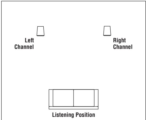
Figure 1. Experiment with speaker placement to obtain the best bass level and stereo imaging in your room.
HOME THEATER
For front-channel use, place one speaker on the left and another on the right, along either side of the television monitor. Since the speakers are magnetically shielded, you can place them near the TV without worrying about the field distorting the TV picture.
For surround-channel use, place speakers on bookshelves or stands alongside the listening position. The ES10 is also wall-mountable. Final placement depends on room acoustics, availability of space and your listening preference (Figures 2 and 3).
In 6- or 7-channel configurations, place the rear channel(s) behind the listening position, as shown in Figures 2 and 3.
NOTE: A JBL powered subwoofer will add impact and realism to both music and film soundtracks. Contact your JBL dealer for recommendations on subwoofer models for your application.
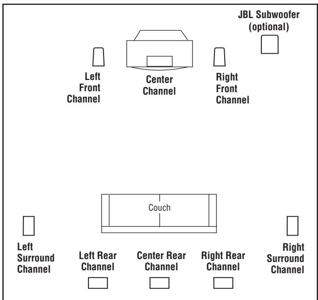
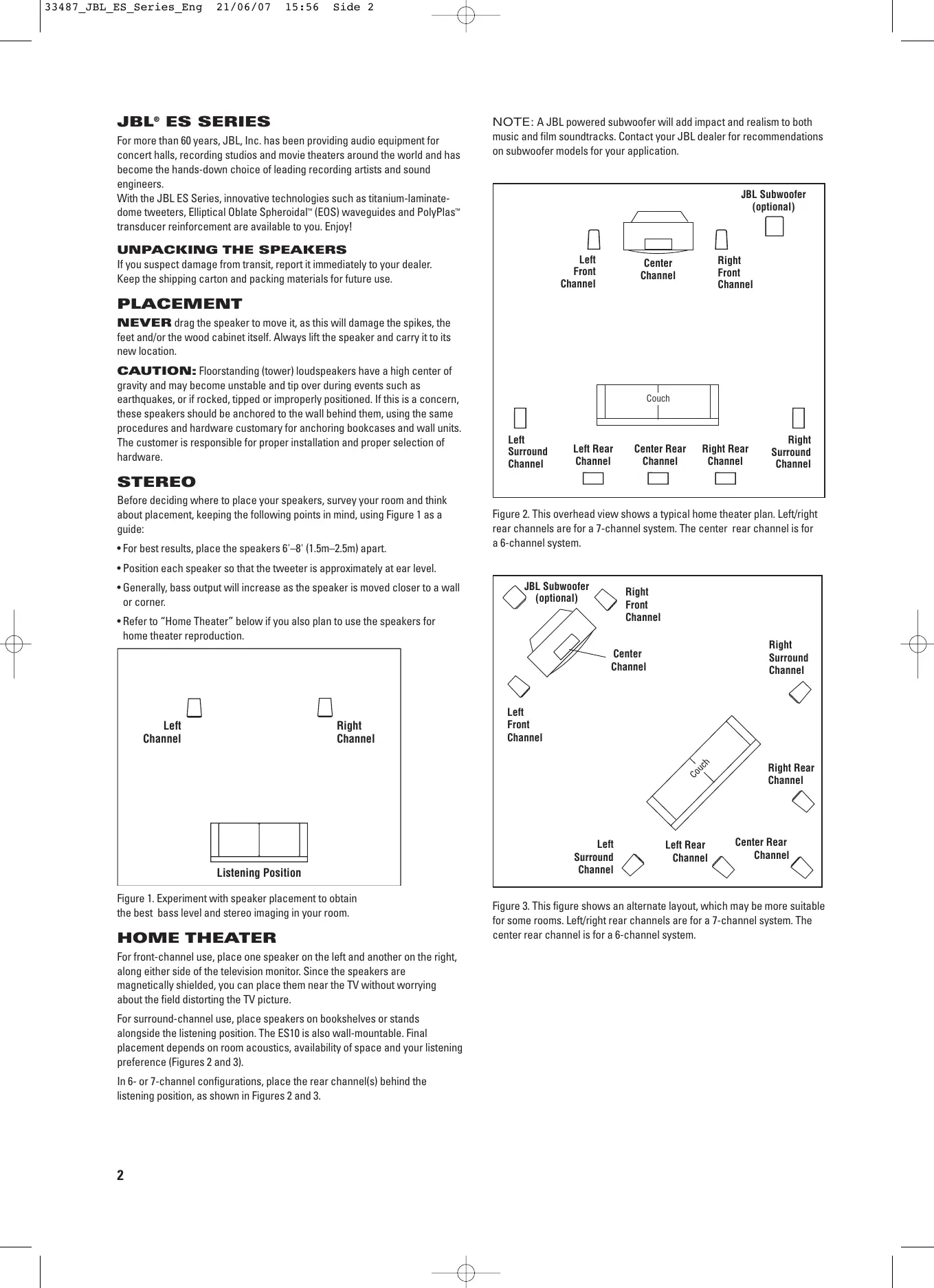
Figure 2. This overhead view shows a typical home theater plan. Left/right rear channels are for a 7-channel system. The center rear channel is for a 6-channel system.
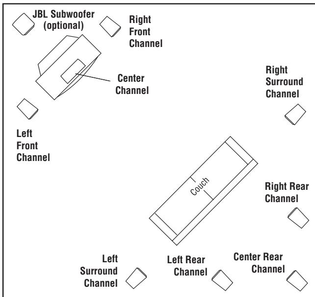
Figure 3. This figure shows an alternate layout, which may be more suitable for some rooms. Left/right rear channels are for a 7-channel system. The center rear channel is for a 6-channel system.
INSTALLING FEET
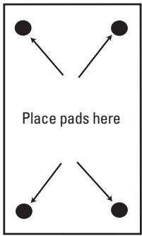
ES10, ES20, ES30
The supplied self-adhesive rubber feet may be attached to the bottom corners of your speakers to protect your furniture.
CHANGING THE FEET
ES80, ES90, ES100
The ES80, ES90 and ES100 feature attractive outboard feet, installed at the factory. However, if you would like to replace them with the less visible inboard feet (included), follow the instructions below.
- Remove the four feet on the bottom of the speaker by loosening the two screws in each foot. Keep the screws for later use.
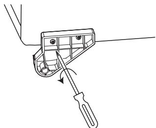
- Attach the black inboard feet to the outer (closest to front of speaker for front feet, closest to rear of speaker for rear feet) holes, from which you just removed the feet, using the same screws you just removed.
- Hand-tighten securely, using a handheld Phillips (+ tip) screwdriver. Do not use a powered screwdriver of any type.
- Replace the screw in the inner hole.
CAUTION: Floorstanding (tower) loudspeakers have a high center of gravity and may become unstable and tip over during earthquakes, or if rocked, tipped or improperly positioned. If this is a concern, these speakers should be anchored to the wall behind them, using the same procedures and hardware customary for anchoring bookcases and wall units. The customer is responsible for proper installation and proper selection of hardware.
INSTALLING SPIKED FEET
ES80, ES90, ES100
Four metal spikes are supplied for use when using the outboard feet and the speaker is to be placed on a carpeted surface, to decouple the speaker from the floor and prevent unwanted damping. To insert the spikes, gently lay the speaker on its side (not its front or back) on a soft, nonabrasive surface. Each spike screws into the threaded insert in each outer foot. Make sure all four spikes are screwed in completely for stability.
NEVER drag the speaker to move it, as this will damage the spikes, the feet and/or the wood cabinet itself. ALWAYS lift the speaker and carry it to its new location.
WALL-MOUNTING
ES10
The ES10 may be wall-mounted. The customer is responsible for proper selection and use of mounting hardware (available through hardware stores), to properly and safely wall-mount the speakers. THESE PRODUCTS ARE NOT INTENDED FOR CEILING MOUNTING.

Two no. 8 round-head or panhead screws should be used per loudspeaker. The screw head should be between 5/16 inch (8mm) and 1/4 inch (6.3mm) in diameter, and the screw should be at least 2 inches (50mm) in length.
When installing screws in any wall, always use properly selected wall anchors. Attach two of the four self-adhesive rubber pads that came with the loudspeaker to the back of the enclosure in the two bottom corners so that the cabinet is spaced evenly from the wall. Select a suitable mounting location on a wall. (The ceiling is not a suitable mounting location.)
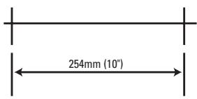
Drill two pilot holes, appropriately sized for the specific self-tapping screw or wall anchor that you will be using. The holes should be 10 inches (254mm) apart. The holes should be 3/4 inch (19mm) below where you want the top of the enclosure to be positioned. Use a carpenter's level to ensure that the holes are even and that the speaker will mount on the level.
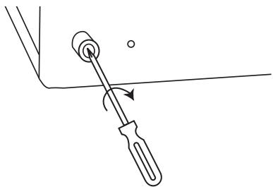
Install the two screws into either a wooden wall stud or anchor, and tighten them until the back of each screw head is about 1/8 inch (3mm) from the wall. Install the loudspeaker by slowly moving the cabinet toward the screws so that the screw heads clear the larger circular portion of the two keyholes. Once both screw heads have entered the keyholes, the loudspeaker should gently be lowered onto the screw shafts. Check that the loudspeaker is firmly locked onto the screws by gently pulling the speaker down and forward.
WIRING THE SYSTEM
IMPORTANT: Make sure all equipment is turned off before making any connections.
For speaker connections, use a high-quality speaker wire with polarity coding. The side of the wire with a ridge or other coding is usually considered positive polarity (i.e., +).
NOTE: If desired, consult your local JBL dealer about speaker wire and connection options.
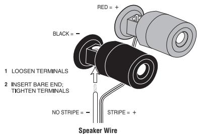
The speakers have coded terminals that accept a variety of wire connectors. The most common connection is shown in Figure 4.
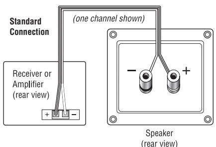
To ensure proper polarity, connect each + terminal on the back of the amplifier or receiver to the respective + (red) terminal on each speaker, as shown in Figure 5. Connect the - (black) terminals in a similar way. See the owner's guides that were included with your amplifier, receiver and television to confirm connection procedures.
Figure 4. This figure shows how to connect bare wires to the terminals.
IMPORTANT: Do not reverse polarities (i.e., + to - or - to +) when making connections. Doing so will cause poor imaging and diminished bass response.
STANDARD CONNECTION
Figure 5. Wiring diagram shows polarity connections for one channel of a stereo or home theater system.
BI-WIRING
ES30, ES80, ES90, ES100
The outer connection panel and internal dividing network of the ES30, ES80, ES90 and ES100 are designed so that separate sets of speaker cables can be attached to the low-frequency transducer and midrange/high-frequency transducer portions of this dividing network. This is called bi-wiring. Bi-wiring can provide several sonic advantages and considerably more flexibility in power amplifier selection.
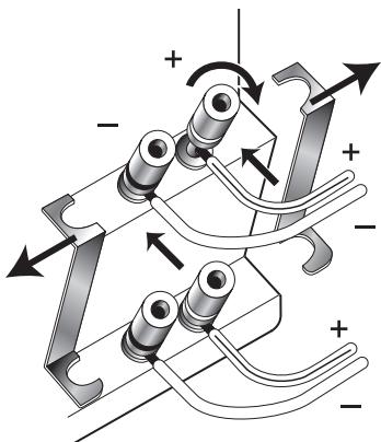
- Loosen the terminals and remove strapping bars.
- Insert the speaker wire for the high frequencies into the top set of terminals and tighten.
- Insert the speaker wire for the low frequencies into the bottom set of terminals and tighten.
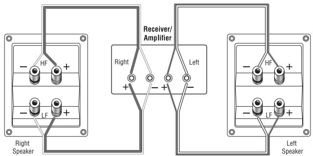
Figure 6.
SINGLE-STEREO AMPLIFIER
Figure 7.
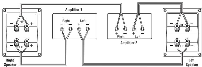
DUAL-STEREO AMPLIFIER
Figure 8.
FINAL ADJUSTMENTS
Check the speakers for playback, first by setting the system volume control to a minimum level, and then by applying power to your audio system. Play a favorite music or video segment and increase the system volume control to a comfortable level.
NOTE: You should hear balanced audio reproduction across the entire frequency spectrum. If not, check all wiring connections or consult the authorized JBL dealer from whom you purchased the system for more help.
The amount of bass you hear and the stereo-image quality will be affected by a number of different factors, including the room's size and shape, the construction materials used to build the room, the listener's position relative to the speakers, and the position of the speakers in the room.
Listen to a variety of music selections and note the bass level. If there is too much bass, move the speakers away from nearby walls. Conversely, if you place the speakers closer to the walls, there will be more bass output.
Each JBL ES Series enclosure has a finish that does not require any routine maintenance. When needed, use a soft cloth to remove any fingerprints or dust from the enclosure or grille.
NOTE: Do not use any cleaning products or polishes on the cabinet or grille.
SPECIFICATIONS
| ES10 | ES20 | ES30 | ES80 | |
| Frequency Response (-3dB) | 65Hz - 40kHz | 60Hz - 40kHz | 50Hz - 40kHz | 45Hz - 40kHz |
| Max. Recommended Amplifier Power* | 100W | 125W | 150W | 200W |
| Power Handling (Continuous/Peak) | 50W/200W | 60W/240W | 70W/280W | 100W/400W |
| Sensitivity (2.83V/1m) | 86dB | 86dB | 88dB | 90dB |
| Nominal Impedance | 8 Ohms | 8 Ohms | 8 Ohms | 8 Ohms |
| Crossover Frequencies | 3000Hz - 24dB/octave;9000Hz - 18dB/octave | 3300Hz - 24dB/octave;12000Hz - 18dB/octave | 3000Hz - 24dB/octave;9000Hz - 18dB/octave | 700Hz, 3600Hz - 24dB/octave;12000Hz - 18dB/octave |
| Low-Frequency Transducer | 4" (100mm) PolyPlas,™shielded | 5" (130mm) PolyPlas,™shielded | 6" (170mm) PolyPlas,™shielded | Dual 6" (170mm) PolyPlas,™shielded |
| Midrange Transducer | NA | NA | NA | 4" (100mm) PolyPlas,shielded |
| High-Frequency Transducer | 3/4" (19mm) Titanium-laminate dome, shielded;EOS waveguide | 3/4" (19mm) Titanium-laminate dome, shielded;EOS waveguide | 3/4" (19mm) Titanium-laminate dome, shielded;EOS waveguide | 3/4" (19mm) Titanium-laminate dome, shielded;EOS waveguide |
| Ultrahigh-Frequency Transducer | 3/4" (19mm) Polyester-film ring-radiator, shielded;EOS waveguide | 3/4" (19mm) Polyester-film ring-radiator, shielded;EOS waveguide | 3/4" (19mm) Polyester-film ring-radiator, shielded;EOS waveguide | 3/4" (19mm) Polyester-film ring-radiator, shielded;EOS waveguide |
| Dimensions With Grille (H x W x D) | 201mm x 305mm x 140mm(7-7/8" x 12" x 5-1/2") | 318mm x 174mm x 203mm(12-1/2" x 6-7/8" x 8") | 387mm x 223mm x 330mm(15-1/4" x 8-3/4" x 13") | 1084mm x 223mm x 330mm(42-11/16" x 8-3/4" x 13") |
| Weight per Speaker | 4kg (8.8 lb) | 4.6kg (10.3 lb) | 8.9kg (19.6 lb) | 21kg (46.3 lb) |
| ES90 | ES100 | ES25C | |
| Frequency Response (-3dB) | 36Hz – 40kHz | 32Hz – 40kHz | 80Hz – 40kHz |
| Max. Recommended Amplifier Power* | 225W | 250W | 150W |
| Power Handling (Continuous/Peak) | 110W/440W | 125W/500W | 75W/300W |
| Sensitivity (2.83V/1m) | 91dB | 91dB | 90dB |
| Nominal Impedance | 8 Ohms | 8 Ohms | 8 Ohms |
| Crossover Frequencies | 500Hz, 3000Hz – 24dB/octave; 12000Hz – 18dB/octave | 450Hz, 3000Hz – 24dB/octave; 12000Hz – 18dB/octave | 3000Hz – 24dB/octave; 12000Hz – 18dB/octave |
| Low-Frequency Transducers | Dual 8" (200mm) PolyPlas,™ shielded | Dual 10" (250mm) PolyPlas,™ shielded | Dual 5" (130mm) PolyPlas,™ shielded |
| Midrange Transducer | 4" (100mm) PolyPlas, shielded | 4" (100mm) PolyPlas, shielded | NA |
| High-Frequency Transducer | 3/4" (19mm) Titanium-laminate dome, shielded; EOS waveguide | 3/4" (19mm) Titanium-laminate dome, shielded; EOS waveguide | 3/4" (19mm) Titanium-laminate dome, shielded; EOS waveguide |
| Ultrahigh-Frequency Transducer | 3/4" (19mm) Polyester-film ring-radiator, shielded; EOS waveguide | 3/4" (19mm) Polyester-film ring-radiator, shielded; EOS waveguide | 3/4" (19mm) Polyester-film ring-radiator, shielded; EOS waveguide |
| Dimensions With Grille (H x W x D) | 1084mm x 260mm x 384mm (42-11/16" x 10-1/4" x 15-1/8") | 1149mm x 305mm x 422mm (45-1/4" x 12" x 16-5/8") | 178mm x 476mm x 254mm (7" x 18-3/4" x 10") |
| Weight per Speaker | 24.2kg (53.4 lb) | 29kg (63.9 lb) | 7.6kg (16.7 lb) |
- The maximum recommended amplifier power rating will ensure proper system headroom to allow for occasional peaks. We do not recommend sustained operation at these maximum power levels.
Declaration of Conformity

We, Harman Consumer Group, Inc. 2, route de Tours 72500 Château du Loir France
declare in own responsibility that the products described in this owner's manual are in compliance with technical standards: EN 61000-6-3:2001 EN 61000-6-1:2001

Laurent Rault
Harman Consumer Group, Inc
Château du Loir, France 5/07
Features, specifications and appearance are subject to change without notice.
JBL is a trademark of Harman International Industries, Incorporated, registered in the United States and/or other countries. Elliptical Oblate Spheroidal, PolyPlas and Pro Sound Comes Home are trademarks of Harman International Industries, Incorporated.
| JBL PRO SOUND COMES HOME™ |
| Harman Consumer Group, Inc., 250 Crossways Park Drive, Woodbury, NY 11797 USA 8500 Balboa Boulevard, Northridge, CA 91329 USA 2, route de Tours, 72500 Château du Loir, France www.jbl.com © 2007 Harman International Industries, Incorporated. All rights reserved. Part No. 406-000-05609-E |
| H A Harman International® Company |