
DX100PC - Extraction fan APPLIED ENERGY - Free user manual and instructions
Find the device manual for free DX100PC APPLIED ENERGY in PDF.
| Product Type | Extractor Fan |
| Brand | APPLIED ENERGY |
| Model | DX100PC |
| Power Supply | 220-240 V ~ 50 Hz, fixed wiring |
| Control Type | Integral pull cord switch |
| Double Insulation | Yes, no earth connection required |
| Possible Mountings | Wall, window, panel, ceiling, ventilation duct |
| Drilling diameter (wall/ceiling) | 115 mm |
| Drilling diameter (window/panel) | 125 mm |
| Acceptable glass thickness | 3 to 6 mm (preferably 4 mm) |
| Acceptable panel thickness | 9 to 46 mm (with DXDG kit) |
| Max. ambient temperature | 50 °C |
| Wiring | 2-core cable |
| Fuse protection | Less than 5 A |
| Functions | Extraction, on/off by pull cord |
| Maintenance | Clean the front cover with a damp cloth or soapy water, do not immerse |
| Prohibited cleaning | Strong solvents, immersion in water |
| Safety | On/Off switch out of reach of bathtub/shower, do not install above a cooker hob |
| Standards | Complies with IEE (UK) and local regulations |
| Supplied accessories | Telescopic wall sleeve, gasket, non-return shutter, screws |
Frequently Asked Questions - DX100PC APPLIED ENERGY
User questions about DX100PC APPLIED ENERGY
0 question about this device. Answer the ones you know or ask your own.
Ask a new question about this device
Download the instructions for your Extraction fan in PDF format for free! Find your manual DX100PC - APPLIED ENERGY and take your electronic device back in hand. On this page are published all the documents necessary for the use of your device. DX100PC by APPLIED ENERGY.
USER MANUAL DX100PC APPLIED ENERGY
Installation and maintenance instructions
DX100 Standard
DX100PC Pull Cord
DX100T Timer
DX100H Humidistat
DX100HP Humidistat and Pull Cord
DX100PIR Integral Body Movement Sensor
DX100VTD Delay Timer
Toilet/Bathroom 100mm/4" Fan Range
Retain for future reference
Xpelair
A
DX100PIR
D
E
B
F
C
G
H
DX100, DX100PC,
DX100HP & DX100PIR
J
DX100H & DX100HP
1
DX100T
K
DX100PIR
Xpelair
Toilet/Bathroom
Fans DX100,
DX100PC, DX100T,
DX100H, DX100HP
DX100PIR &
DX100VTD
installation &
operating
instructions
Please leave this leaflet with the fan for the benefit of the user
Installing the fan
These appliances are intended for connection to fixed wiring. Check that the electrical rating shown on each fan matches the mains supply.
THESE APPLIANCES ARE DOUBLE INSULATED AND DO NOT REQUIRE AN EARTH CONNECTION.
All installations must be supervised by a qualified electrician. Installations and wiring must conform to current IEE Regulations (UK), local or appropriate regulations (other countries).
If you have any queries before installing these products or after they have been installed, call the Xpelair Technical Hotline +44 (0) 8709 000430. Our engineers are there to help you during normal office hours (UK only) and may be faxed at all other times on +44 (0) 8709 000530.
Customers outside the UK should contact your local Xpelair distributor.
Description
Xpelair fans have the following features:
Universal mounting kit allows window/ wall panel/ ventilation shaft/ ceiling mounting options.
- Single speed extraction
DX100
- Operate the fan using an on/off switch (not supplied).
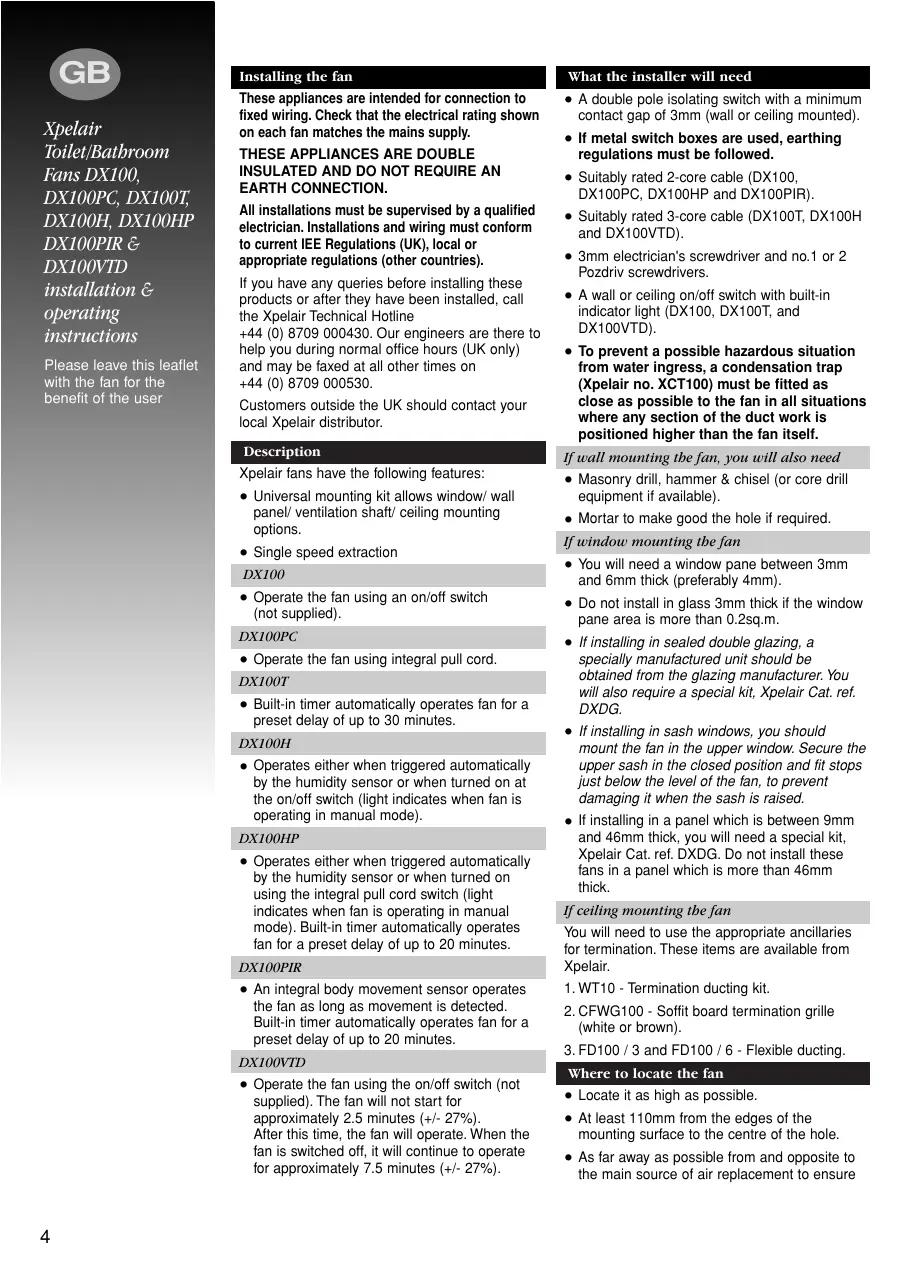
DX100PC
- Operate the fan using integral pull cord.
DX100T
- Built-in timer automatically operates fan for a preset delay of up to 30 minutes.
DX100H
- Operates either when triggered automatically by the humidity sensor or when turned on at the on/off switch (light indicates when fan is operating in manual mode).
DX100HP
- Operates either when triggered automatically by the humidity sensor or when turned on using the integral pull cord switch (light indicates when fan is operating in manual mode). Built-in timer automatically operates fan for a preset delay of up to 20 minutes.
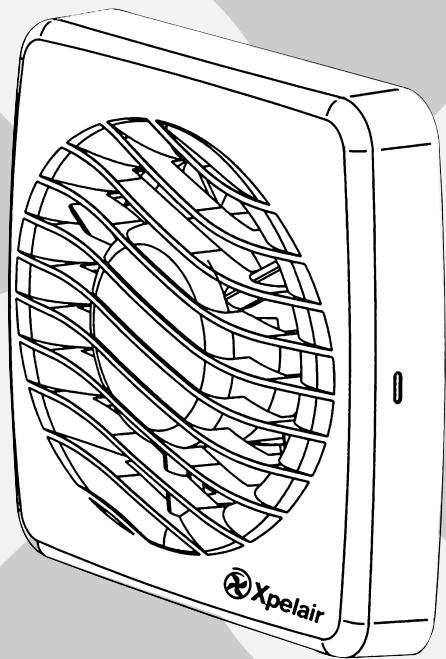
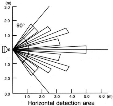
DX100PIR
- An integral body movement sensor operates the fan as long as movement is detected. Built-in timer automatically operates fan for a preset delay of up to 20 minutes.
DX100VTD
- Operate the fan using the on/off switch (not supplied). The fan will not start for approximately 2.5 minutes (+/- 27%) . After this time, the fan will operate. When the fan is switched off, it will continue to operate for approximately 7.5 minutes (+/- 27%) .
What the installer will need
- A double pole isolating switch with a minimum contact gap of 3mm (wall or ceiling mounted).
- If metal switch boxes are used, earthing regulations must be followed.
- Suitably rated 2-core cable (DX100, DX100PC, DX100HP and DX100PIR).
- Suitably rated 3-core cable (DX100T, DX100H and DX100VTD).
- 3mm electrician's screwdriver and no.1 or 2 Pozdriv screwdrivers.
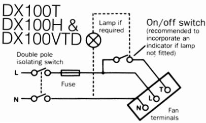
- A wall or ceiling on/off switch with built-in indicator light (DX100, DX100T, and DX100VTD).
- To prevent a possible hazardous situation from water ingress, a condensation trap (Xpelair no. XCT100) must be fitted as close as possible to the fan in all situations where any section of the duct work is positioned higher than the fan itself.
If wall mounting the fan, you will also need
- Masonry drill, hammer & chisel (or core drill equipment if available).
- Mortar to make good the hole if required.
If window mounting the fan
- You will need a window pane between 3mm and 6mm thick (preferably 4mm).
- Do not install in glass 3mm thick if the window pane area is more than 0.2sq.m.
- If installing in sealed double glazing, a specially manufactured unit should be obtained from the glazing manufacturer. You will also require a special kit, Xpelair Cat. ref. DXDG.
- If installing in sash windows, you should mount the fan in the upper window. Secure the upper sash in the closed position and fit stops just below the level of the fan, to prevent damaging it when the sash is raised.
- If installing in a panel which is between 9mm and 46mm thick, you will need a special kit, Xpelair Cat. ref. DXDG. Do not install these fans in a panel which is more than 46mm thick.
If ceiling mounting the fan
You will need to use the appropriate ancillaries for termination. These items are available from Xpelair.
- WT10 - Termination ducting kit.
- CFWG100 - Soffit board termination grille (white or brown).
- FD100 / 3 and FD100 / 6 - Flexible ducting.
Where to locate the fan
- Locate it as high as possible.
- At least 110mm from the edges of the mounting surface to the centre of the hole.
- As far away as possible from and opposite to the main source of air replacement to ensure
airflow across the room (e.g. opposite the internal doorway).
- Near the source of steam or odours.
- Not where ambient temperatures are likely to exceed 50^ .
- If installed in a kitchen fans must not be mounted immediately above a cooker hob, or eye level grill.
- If installing in a room containing a fuel burning device which has a non-balanced flue, it is the installer's responsibility to ensure that there is enough replacement air to prevent fumes being drawn down the flue when the fan is operating up to maximum extract. Refer to Building Regulations for specific requirements.
- Exhaust air must not be discharged into a flue used for exhausting of fumes from appliances supplied with energy other than electric. Requirements of all authorities concerned must be observed for exhaust air discharge and intake flow rates.
- When intended for use in possible chemical corrosive atmospheres, consult out Technical Service Department. (For overseas markets contact your local Xpelair distributor).
- DX100PIR Only - Siting must ensure detection of movement. Care should be taken to avoid obstruction that may affect detection beams A.
Installing the isolating switch and cables
- Check that the electrical rating shown inside the back plate matches your mains supply.
- Check there are no buried pipes or cables e.g. electricity, gas, water behind the switch location (in the wall or above the ceiling). If in doubt, seek professional advise.
- Isolate the mains supply.
- Lay in the cable from the isolating switch to the fan location via the on/off switch (if required).
- Lay in the cable from the isolating switch to the point of connection to the mains supply.
- Install the isolating switch and on/off switch (if required).
- Make all connections within the isolating switch and the on/off switch (if required).
Note: on/off switch must be situated so that it cannot be touched by persons making use of the bath or shower.
WARNING:DO NOT MAKE ANY CONNECTIONS TO THE ELECTRICAL SUPPLY AT THIS STAGE.
For Australia only (DX100, DX100PC. DX100HP & DX100PIR)
Connection to the supply can be made by a
flexible 2-core cable complete with 3 pin plug for insertion into an approved 10 amp GPO or directly wired through an approved 10A wall-mounted surface switch with at least 3mm clearance between contacts.
For Australia only (DX100T, DX100H & DX100VTD)
These models are permanently connected to the supply and operation is controlled by a remote switch. They should be directly wired to the supply through an approved 10amp wall mounted surface switch with at least 3mm clearance between contacts.
WARNING : CHILDREN SHOULD NOT PLAY WITH THE APPLIANCE AND ENSURE THAT YOUNG CHILDREN AND THE INFIRM ARE SUPERVISED
Preparing the hole
If working above ground floor level, appropriate safety precautions must be observed.
WARNING: EYE PROTECTION MUST BE WORN DURING ALL DRILLING AND CHISSELLING OPERATIONS.
If installing in a wall
- Check there are no buried pipes or cables in the wall or obstructions on the outside e.g. electricity, gas, water. If in doubt, seek professional advise.
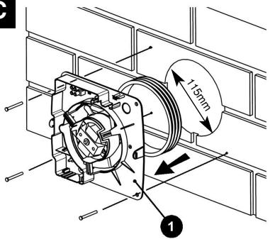
- Mark on the wall the centre of the duct hole.
- Use this centre to mark a circle to suit the wall duct (115mm diameter).
If core drill equipment is available:
4a. Use as directed by core drill manufacturer.
If core drill equipment is not available:
4b. Drill a centre hole right through the wall.
- Cut the hole. Do not cut right through the wall. (The recommended method is to drill a series of holes, close together, around the edge of the cutting line and remove the brick between the holes with a chisel).
- Go outside and cut a hole in the outer wall, repeating the process described above.
- Cut ducting to the correct length if required. The wall tube supplied is telescopic and can extend to 300mm maximum.
- Fit the ducting. Ensure that the duct slopes down away from the fan to allow drainage of any incoming rain water to the outside.
- Make good the hole. Allow the mortar to set before continuing the fan installation.
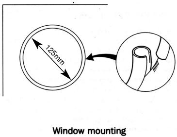
If installing in a window or panel
- Cut a hole, 125mm in diameter or if installing in a window, obtain a ready cut pane.
- The centre of the hole should be at least 110mm away from the edge of the panel or pane of glass.
If installing in a ventilation sbaft
- Check there are no buried pipes or cables in the ventilation shaft. If in doubt, seek professional advise.
- Cut a hole 110mm in diameter, in the side of the shaft.
Xpelair Toilet/Bathroom
Fans DX100, DX100PC, DX100T, DX100H, DX100HP
DX100PIR &
DX100VTD
installation &
operating instructions
Please leave this leaflet with the fan for the benefit of the user
- If the shaft has cavity wall, use the wall tube to bridge the cavity.
- Fit ducting and condensation trap if necessary, positioning condensation trap as near to the fan as possible.
If installing in a ceiling
- Check there are no buried pipes or cables in the ceiling/joists etc. If in doubt, seek professional advise.
- Cut a hole 115mm diameter.
Preparing the fan for installation
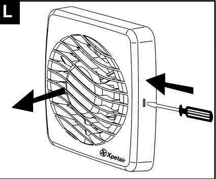
Remove the front cover by pressing the release catches located on the sides of the unit with a 3mm screwdriver, whilst pulling the front cover forward L
Mount the fan in the hole
If working above ground floor level, appropriate safety precautions must be observed.
If installing in a wall, ceiling or vent
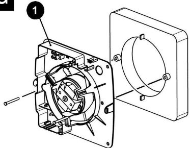
Mark the position of the back plate 3
- Hold the backplate so that the terminal block faces you in the top left hand corner and the lip points towards the hole.
- Carefully insert the lip into the wall duct/ceiling or vent shaft.
- Adjust the position of the back plate until it is level.
- Mark on the wall/ceiling or vent shaft the positions of the three fixing holes in the back plate.
- Remove the back plate from the ducting.
- Drill screw holes in these positions if necessary, and fit wall plugs if necessary.
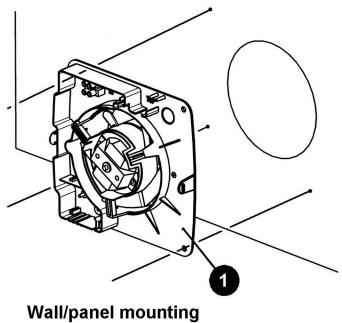
Mount the back plate
- Push the ribbed gasket (RG100) onto the lip of the back plate 1
- If installing in a ceiling or vent, push the larger diameter piece of the telescopic wall tube onto the ribbed gasket. Cut the tube to the required length first, if necessary.
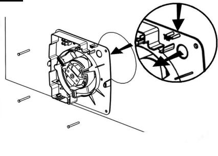
- If wiring the fan from behind, remove knockout. Feed the mains cable through the cable entry hole in the back plate to the terminals D
- If wiring from above, leave the cable free to be fitted into labyrinth.
- Insert the lip of the back plate into the wall duct/ceiling or vent shaft as before.
- Fasten the back plate to the wall/ceiling or vent shaft using appropriate fasteners. If using screws, do not overtighten the screws.
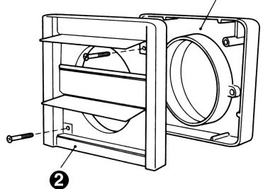
Mount the back draught shutter
- Peel the backing from the foam strip supplied and attach it around the outside of the lip on the back draught shutter.
-
Go outside. Holding open the top and bottom vanes, insert the lip into the wall duct.
-
Making sure that the back draught shutter is level, mark the positions of the two fixing holes in the top right hand and bottom left hand corners.
- Remove the back draught from the wall duct.
- Drill screw holes in these positions, and fit the remaining wall plugs.
- Holding open the top and bottom vanes, refit the back draught shutter and fasten it to the wall using the pointed and self-tapping screws. Do not over tighten screws.
- Make sure that the vanes open and shut freely.
If installing in window or panel
Sealing the hole E
- If installing in a window or panel no more than 9mm thick, fit the white rubber gasket around the edge of the hole. If installing in a panel or sealed double glazing more than 9mm thick, a DXDG double glazing kit is required. Follow the instructions supplied with the special kit.
Attach the back draught shutter to the spacer
- Holding the top and bottom vanes, insert the back draught shutter into the spacer so that the fixing holes in the top right and bottom left hand corners match those on the spacer.
- Insert two of the flat ended self-tapping screws provided and fasten the back draught shutter to the spacer.
Mount the fan in the window
- Someone else must hold the back draught shutter and spacer in position outside, with the spacer against the glass.
- Make sure that the two raised fixing holes in the spacer are horizontal and are positioned within the hole.
- From inside, hold the back plate so that the terminal block faces you in the top left hand corner and the lip points towards that hole.
- Align the holes in the back plate with those in the spacer.
- Insert two of the flat ended self-tapping screws provided in the fixing holes, and fasten the back plate to the spacer. Do not overtighten the screws.
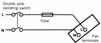
Wire the electrical connections
- Make sure the mains supply is isolated,
- Wire the fan as shown in check the fan model to diagram, feeding the cable between the two raised pegs, if wiring from above, and through labyrinth to terminal block.
- Switch off the mains electrical supply and remove fuses
- Connect the cable from the isolating switch to the electrical supply wiring.
- For fixed wiring circuits the protective
fuse for the appliance must not exceed 5A.
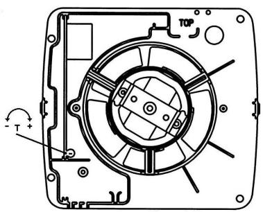
DX100T only 1
- To adjust the over-run period turn the control (T) clockwise to increase and anti-clockwise to decrease.
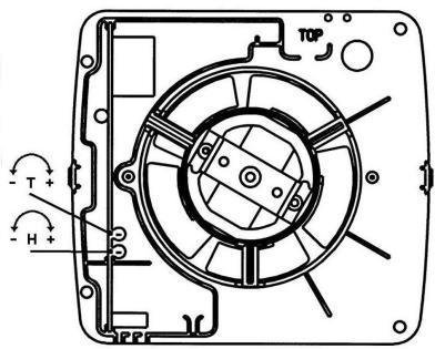
DX100H & DX100HP only J
- Humidity operation is factory set at approx. 70% Relative Humidity (RH), but can be adjusted between 50% and 90% RH by control(H).
- Time delay is factory set at approx. 20 mins, but can be adjusted by control (T).
- Both controls are adjustable. Turn the controls clockwise to increase time or RH, and anticlockwise to decrease.
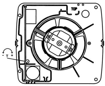
DX100PIR only K
- Adjust the overrun period with control (T).
Turn screwdriver clockwise to increase and anti-clockwise to decrease.
All fans
- If wiring from above cut out the cable entry slot marked on top of the front cover.
- Fit the front cover by aligning it square to the duct and pushing it onto the duct until the release catches snap into the slots on the front cover.
Using the fan
DX100 & DX100VTD only
- Operate the fan using the on/off switch. Repeat to switch off.
DX100PC only
- Operate the fan by pulling and releasing the cord. Repeat to switch off.
DX100T only
- Operate the fan using the on/off switch. When the switch is turned off, the fan continues to operate for the adjustable time delay.
DX100H only
- Manual mode: use the on/off switch. When you switch off, the fan goes into automatic mode after the time delay (light indicates when fan is operating in manual mode).
Automatic mode: fan operates when relative humidity rises and turns off again when humidity drops.
DX100PIR only
- The sensor detects movement in the room and activates the fan. When movement is sensed, the fan will run for a pre-set overrun period and any further movement sensed will re-start the sequence. This ensures that the room is only ventilated during and immediately after use. When the fan is first installed there will be a stabilising period of approximately five minutes. During this time the fan will run for up to two minutes.
Cleaning (recommended once a month)
A QUALIFIED ELECTRICIAN MUST CARRY OUT ALL CLEANING.
- Before cleaning, isolate the fan completely from the mains supply.
- Remove the front cover by pressing the release catches located on the sides at the unit with a 3mm screwdriver, whilst pulling the front cover forward L
- To clean the front cover, either wipe it with a damp, lint free cloth or wash it in warm soapy water. Thoroughly dry the front cover and refit.
- Do not immerse the fan in water or other liquids to clean any other parts of the fan.
- Never use strong solvents to clean the fan.
- Apart from cleaning, no other maintenance is required.
DX100 & DX100VTDsubsection
(\Gamma \varepsilon \nu \kappa \kappa \kappa \kappa \kappa \kappa \kappa \kappa \kappa \kappa \kappa \kappa \kappa \kappa \kappa \kappa \kappa \kappa \kappa \kappa \kappa \kappa \kappa \kappa \kappa \kappa \kappa \kappa \kappa \kappa \kappa \kappa \kappa \kappa
Eeaywniiaq taxtuTntac.
DX100
O eEaepiortipac aeitoupyei tn xpon diakontn on/off (nou denvapexetai).
DX100PC
O eEaepiataipac aeitoupeyie t n xpon EvwaatwEvov kopodiovu tropahyuatoC.
DX100T
Móvo yia to DX100T 7
Iva puthetaiEe Tn nepioo unepbaonc yupicTe To xeiipotnoio (T) ouuwova t n opa tou poIoou yia va Tn auEioeKai avtiEeta poc T npopa tou poIoou yia va tn meoote.
Móvo yia ta DX100H kai DX100HP 7
H etoupia tnc uypaia c ivai puthetaiaevn ano to epyootaoio o xetik npyada npiinou 70% , aaaaiv dektiukpuhuiang o xetikuypaia metae npinou 50 % kai 90% uexipiotipio (H).
O xpoVoc uTepBaon eivai puHuaievoc ano to epyoataioe neptinou 20 deutepoIenTa aAaMupoei va puHuaeiEe xeiipotnIO (T).
Xpelair
Avεμιοτηρες
Touaλετας
μανίου DX100,
DX100PC,
DX100T
DX100H
DX100HP
DX100PIR &
DX100VTD
Odyies sykataoanaKai
Aitoupyia
Napakalee b' aogote Toa
- 5-6-7-8-9-10-11-12-13-14-15-16-17-18-19-20-21-22-23-24-25-26-27-28-29-30-31-32-33-34-35-36-37-38-39-40-41-42-43-44-45-46-47-48-49-50-51-52-53-54-55-56-57-58-59-60-61-62-63-64-65-66-67-68-69-70-71-72-73-74-75-76-77-78-79-80-81-82-83-84-85-86-87-88-89-90-91-92-93-94-95-96-97-98-99-100
Móvo yia to DX100PIK
PuizTe Tny npiioo unepbaonc me To xeiipotnio (T). TupceTe to katoaBiou omuwva me Tn fopa tou pooloyiou ia va Tnu auEgote Ka avtiEte npoc Tnv foopa Tou pooloyiou ia va Tn eWOTe.
Oλοι o Εξαεριστίρες
Av n kaawoiyivetai an ta naew, anokoyteynv yekorn iioobou kawdiou nou eival onaadeevn oanwepoc tou mnpoovoukaumuatoc.
To08TeTnE To mnpoTivo kALUMa eUuypauiOvTacTo TepaywVikaeTov ayuoykaiOnpXyovTacTo enawOTov ayuvoexpiVa apnAevou Ta maojata anEeuBepOWcMeoStcEyKonecTOU npooTIVou KAULmuAToc.
Móvo yia to DX100PIR
O aioθntɪpɑac avixveɪe kivɒn μεσa ɑtō δμʌtio kai evpyɔniəi tov εæpiotɪpɑ. Šətav eɪŋʌmavɛi kivɒn, o Eæpiotɪpɑkø θa λειούργηər iə yia miː npʊpʊθμαɪevn περiodo untpβaʊn kai oæ kθe aʌλŋ περɪntwɒn nʊ θa eɪŋʌmuaɪvætai kivɒn n
diabikaaia autn tha enavaalaBavetai. AutodiaqpaIzE ot to duatio EaepiZeTau mvo kata tn diapkeia tnc xpnoc kai metao anutm. Meta nTv apxk EYKATAOTou Eaepiotnpa 0a unapeimu atbeponoiTnik npiooC npinou nve TLeNTw. Kata tn diapkeia Tc npioDou autn, o Eaepiotnpac 0a eipyoupnaei via mexpi kai duo IeTt.
WARNING: ANSLUT INTE TILL ELNÄTET I DETTA SKEDE.
a aaiia aiai aia iiai aaiia aaiia aaiia aaiia aaiia aaiia aaiia aaiia aaiia aaiia aaiia aaiia aaiia aaiia aaiia aaiia aaiia aaiia aaiia aaiia aaiia aaiia aaiia aaiia aaiia aaiia aaiia aaiia aaiia aaiia aaiia aaiia aaiia aaiia
1
J.
baa yg yg .y
.
biSg.
15b1. 15b1/15aill tlao p15uily aagall Jauo . 15aall yaii tay gia Jaai aygall aaii tlaal
1
sioe .iei /jiai i 1000000000000000000000000000000000000000000000000000000000
()
aagbll Jae aie lae aee rall Jae: gllg 8
S_ OBC = 12 · CO · BC = 12 × CD × 5
aasjg jaiy jay yjuyuuiy jay uieo iiai aaiy jay yjuyuuiy jay uiei yjuyuai
yj yj jyj yj yj yj yj yj yj yj
a a a a a a a a a a a a a a a a a a a a a a a a a a a a a a a a a
gai jai kai kai jai kai jai kai jai kai jai kai jai kai jai kai jai kai jai kai jai kai jai kai jai kai jai kai jai kai jai kai jai kai jai kai jai kai jai kai jai kai jai kai jai kai jai kai jai kai jai kai jai kai
alill oljy glll ygall alll jol .
Lguydiie jyusualln yjusuall uo 0
y. selalgl lgllll gssgall no ydsasall
gulgllll alalall
a
Jg20 1y jy
H 10000000000000000000000000000000000000000000000000000000000000000000
y
Jlll JdLJ LdL WJ Jall Cldo JSS Jg 1
j 1 j 1 j 1 j 1 j 1 j 1 j 1 j 1 j 1 j 1 j 1 j 1 j 1 j 1 j 1 j 1 j 1 j 1 j 1 j 1 j 1 j 1 j 1 j 1 j 1 j 1 j 1 j 1 j 1 j 1 j 1 j 1 j 1 j 1 j
1 kss s
gai gao 15s gi uui li jao sui 1
...
PO = 110 L_B OQ = 2 P( 12) .
#
aessssssssssssssssssssssssssssssssssssssssssssssssssssssssssssssssssssssssssssssssssssssssssssss
L
aaii
y
aalaaalalalalalalalalal
aaii i jii jilbla lcui
B aalal algall lss
1 1 1 1 1 1 1 1 1 1 1 1 1 1 1 1 1 1 1 1 1 1 1 1 1 1 1 1 1 1 1 1 1 1 1 1 1 1
i#
/lailllgl aaii iiaai 1aai iiaai
0
jll jll lglalall aie gao yolol oolai 1
C a.s.l.l.a.s.l. s
a(1…)aialljai
1 a
gall jll gai aai gai gai ale lglj 1
le gsslll lal bai jn no jll jall jgsi
Jall sui yai jai jai jai!
1 1 1 1 1 1 1 1 1 1 1 1 1 1 1 1 1 1 1 1 1 1 1 1
D
JdI J 1J 1J 1J 1J 1J 1J 1J
a#g/1blll 0
aaii aai i aai /aii /aii /aii /aii /aii /aii /aii /aii /aii /aii /aii /aii /aii
aall 100000000000000000000000000000000000000000000000
a
1 1 1 1 1 1 1 1 1 1 1 1 1 1 1 1 1 1 1 1 1 1 1 1 1 1 1 1 1 1 1 1 1
()
pail pial lall jalai yll aol oal 00
oal Jaiy iay, ayie pe cilll alaay laiia
gaiy ciae yj e ayar lall aal yall
llia jy j bai llal ie yaiy 1. ydi dae
Jaiy lali yoi po r jzdy f
Lajgall gaiy j j Jabi dy j
Jaiy Jabi yaiy j
#
1s 1s 1s 1s 1s 1s 1s 1s 1s 1s 1s 1s 1s 1s 1s 1s 1s 1s 1s 1s 1s 1s 1s 1s 1s 1s 1s 1s 1s 1s 1s
lll jg jlaai jn j g yll bbl 1
yss! pj rnnss) a kki dauu uus uynu
jag aegall no sao nol so ygi (1 1
uuu lal jae jg i g ngk gll llll
. gaaiaaagall no g ie al
1
()
a
aillll jililil "jililil" 1
c//sdiilllglccuulllal yallllllllpbl 1 //yqjia /biI
dsalg cysb
- · S( 1 + u)
()
G
aayy jolkio dllpduwiyiaagai J
()
a
()
jg.1.ygbblly jzabwgl bll: jycbjka Jaa loic Lao yks)Liby/ Jauu c tia. ybj . (gsdall
()
j 1ybl yu wyy jy bawl llo: jy bdy jaoi
jy) uuy pui lokio uuu cfo pl iuyu lyaiu ci
(ydall g aagll g aagall laa Ldoic Ldoe ayall
y taasss saaed sall aggall jayleal ll qagall
.
1 5
aagall jzpwqglg 2y yw wll Jokll qj .
laliagall jzwlqdl all cagall . 4y 10.
.
S_ ACD = 12 · AC · PD = 12 × CD × PD = CD.
(co).lab/1jieiillclaoipidiyuoyall jai· Luytaaiguiyueo 1jiaLyaogall.(agall ayall. labiie.ayall Jaaosdaiy. (% V - + ) (/Y-/+) (/Y-+)
Notes
DX100,
DX100PC,
DX100T, DX100H
DX100HP
DX100PIR &
DX100VTD

Do's and dont's
- Do read all the instruction leaflet before commencing installation.
- Do install each fan with a double pole isolating switch with a contact gap of 3mm in each pole.
- Do make sure the mains supply is switched off before attempting to make electrical connections or carry out any maintenance or cleaning
- Don't install this fan in any window/panel which is less than 4mm thick.
Guarantee
Customers outside UK - see international below.
- UK: The fan is guaranteed against defects for 3 years from the date of purchase.
- Please keep your purchase receipt.
- If you have any problems, contact Xpelair's Head Office at the address shown below.
Technical advice and service
Customers outside UK - see international below.
UK: Xpelair have a comprehensive range of services including:
- Free technical advice help-desk from Engineers on all aspects of ventilation.
- Free design service, quotations and site surveys.
Service and maintenance contracts to suit all requirements.
Please ask for details:
- By telephone on Techline: +44 (0) 8709 000430
By fax on Techfax: +44 (0) 8709 000530 - At the address below
Head Office, UK Sales Office and Spares
Applied Energy Products Ltd, Morley Way, Peterborough, PE2 9JJ England
Telephone: +44 (0) 1733 456789
Fax: +44 (0) 1733 310606
Sales/Spares Hotline: +44 (0) 8709 000420
Sales/Spares Faxline: +44 (0) 8709 000520
http://www.xpelair.co.uk
International
- Guarantee: Contact your local distributor or Xpelair direct for details.
- Technical Advice and Service: Contact your local Xpelair distributor.