
CONTROL 5.2 - Audio Mixer SYNQ AUDIO RESEARCH - Free user manual and instructions
Find the device manual for free CONTROL 5.2 SYNQ AUDIO RESEARCH in PDF.
| Product type | Audio mixing console |
| Brand | SYNQ AUDIO RESEARCH |
| Model | CONTROL 5.2 |
| Dimensions | 483 (W) x 134 (H) x 130 (D) mm |
| Weight | 2 kg |
| Power supply | AC 230 V, 50 Hz |
| Fuse | 20 mm glass, 250 V, 500 mA, slow-blow |
| Frequency response | 20 - 20,000 Hz (+/- 2 dB) |
| Total harmonic distortion + noise | < 0.1% at 1 kHz, 0 dB |
| Signal-to-noise ratio | > 85 dB (IHF-A) at 1 kHz |
| Microphone inputs | 5 x balanced XLR, sensitivity 1.5 mV @ 10 kΩ |
| Line/CD inputs | 4 x RCA, sensitivity 150 mV @ 22 kΩ |
| Phono inputs | 2 x RCA, sensitivity 3 mV @ 47 kΩ |
| Record outputs | 2 x RCA, level 775 mV @ 600 Ω |
| Unbalanced Master A/B outputs | 2 x RCA, level 1.5 V @ 4.7 kΩ |
| Balanced Master A/B outputs | 2 x XLR, level 850 mV @ 600 Ω |
| Headphone output | 6.3 mm stereo jack, 1 V @ 33 Ω |
| Tone control | 3-band (treble, mid, bass), +/- 12 dB at 10 kHz / 1 kHz / 100 Hz |
| Talkover | Adjustable attenuation from 0 dB to -15 dB |
| Independent zones | 2 zones (A and B) with balanced XLR and unbalanced RCA outputs |
| Input channels | 5 channels, each with gain, 45 mm fader, zone assignment, signal/peak LED indicators |
| PFL functions | Rotary selector, adjustable level, 6.3 mm headphone jack |
| Max operating temperature | 45 °C |
| Cleaning | Soft cloth slightly damp; avoid abrasive liquids |
| Safety | Do not open, do not expose to rain or moisture, unplug if not used for extended periods |
Frequently Asked Questions - CONTROL 5.2 SYNQ AUDIO RESEARCH
User questions about CONTROL 5.2 SYNQ AUDIO RESEARCH
0 question about this device. Answer the ones you know or ask your own.
Ask a new question about this device
Download the instructions for your Audio Mixer in PDF format for free! Find your manual CONTROL 5.2 - SYNQ AUDIO RESEARCH and take your electronic device back in hand. On this page are published all the documents necessary for the use of your device. CONTROL 5.2 by SYNQ AUDIO RESEARCH.
USER MANUAL CONTROL 5.2 SYNQ AUDIO RESEARCH
Copyright © 2010 by BEGLEC NV
t Hofveld 2C B1702 Groot-Bijgaarden Belgium
Reproduction or publication of the content in any manner, without express permission of the publisher, is prohibited.
CE
Version: 1.0
JBSYSTEMS
THE POWER SOURCE FOR DJ'S


EN - DISPOSAL OF THE DEVICE
Dispose of the unit and used batteries in an environment friendly manner according to your country regulations.
FR-DECLASSES L'APPAREIL
- 2 Independent Zones, each with balanced XLR-output (+unbalanced on cinch)
Each zone has 3band tone controls, balance, volume and mono/stereo switch - 11 inputs on 5 Channels (5 balanced mic + 4line + 2phono)
- 1Microphone with 3band tone control and zone assignable adjustable talkover.
- Every Channel can be assigned to zone A, zone B or both.
- Every Channel has individual peak and signal present leds.
- Gain levels and 45mm faders on all channels
- PFL with rotary selector, cue level adjustment and 6.3mm headphones jack.
- 2 independent record outputs without Channel1 microphone and free from talkover muting.
BEFORE USE
CHECK THE CONTENTS:
Check that the carton contains the following items:
- CONTROL5.2 / MIX5.2 Mixer unit
- Operating instructions
- Mains cable
SAFETY INSTRUCTIONS:

CAUTION
RISK OF ELECTRIC SHOCK DO NOT OPEN

CAUTION: To reduce the risk of electric shock, do not remove any cover. No user-serviceable parts inside. Refer servicing to qualified service personnel only.

The lightning flash with arrowhead symbol within the equilateral triangle is intended to alert the use or the presence of un-insulated "dangerous voltage" within the product's enclosure that may be of sufficient magnitude to constitute a risk of electric shock.
The exclamation point within the equilateral triangle is intended to alert the user to the presence of important operation and maintenance (servicing) instructions in the literature accompanying this appliance.
This symbol means: indoor use only.
This symbol means: Read instructions.
- To prevent fire or shock hazard, do not expose this appliance to rain or moisture.
- To avoid condensation to be formed inside, allow the unit to adapt to the surrounding temperatures when bringing it into a warm room after transport. Condense sometimes prevents the unit from working at full performance or may even cause damages.
-
This unit is for indoor use only.
-
Don't place metal objects or spill liquid inside the unit. No objects filled with liquids, such as vases, shall be placed on this appliance. Electric shock or malfunction may result. If a foreign object enters the unit, immediately disconnect the mains power.
- No naked flame sources, such as lighted candles, should be placed on the appliance.
- Don't cover any ventilation openings as this may result in overheating.
- Prevent use in dusty environments and clean the unit regularly.
- Keep the unit away from children.
- Inexperienced persons should not operate this device.
- Maximum save ambient temperature is 45^ . Don't use this unit at higher ambient temperatures.
- Minimum distances around the apparatus for sufficient ventilation is 5cm .
- Always unplug the unit when it is not used for a longer time or before you start servicing.
- The electrical installation should be carried out by qualified personal only, according to the regulations for electrical and mechanical safety in your country.
- Check that the available voltage is not higher than the one stated on the rear panel of the unit.
- The socket inlet shall remain operable for disconnection from the mains.
- The power cord should always be in perfect condition: switch the unit immediately off when the power cord is squashed or damaged.
- Never let the power-cord come into contact with other cables!
- In order to prevent electric shock, do not open the cover. Apart from the mains fuse there are no user serviceable parts inside.
- Never repair a fuse or bypass the fuse holder. Always replace a damaged fuse with a fuse of the same type and electrical specifications!
- In the event of serious operating problems, stop using the appliance and contact your dealer immediately.
- Please use the original packing when the device is to be transported.
- Due to safety reasons it is prohibited to make unauthorized modifications to the unit.
INSTALLATION GUIDELINES:
- Install the unit in a well-ventilated location where it will not be exposed to high temperatures or humidity.
- Placing and using the unit for long periods near heat-generating sources such as amplifiers, spotlights, etc. will affect its performance and may even damage the unit.
- The unit can be mounted in 19-inch racks. Attach the unit using the 4 screw holes on the front panel. Be sure to use screws of the appropriate size. (screws not provided) Take care to minimize shocks and vibrations during transport.
- When installed in a booth or flight case, please make sure to have good ventilation to improve heat evacuation of the unit.
- To avoid condensation to be formed inside, allow the unit to adapt to the surrounding temperatures when bringing it into a warm room after transport. Condense sometimes prevents the unit from working at full performance.
CLEANING THE MIXER:
Clean by wiping with a polished cloth slightly dipped with water. Avoid getting water inside the unit. Do not use volatile liquids such as benzene or thinner which will damage the unit.
CONNECTIONS
Except for microphones, headphone and zone outputs, all connections are cinch. Use good quality cinch-cinch cables to prevent bad audio quality. (example: JB Systems code: 2-0370)
For more information on connections, please refer to the next chapter.
Be sure to turn off the mixer before you make changes to the different connections.
In this manual we talk about "line inputs". This is a global name for inputs with a level between 750mV and 2V. This includes tuners, videos, CD-players, etc.
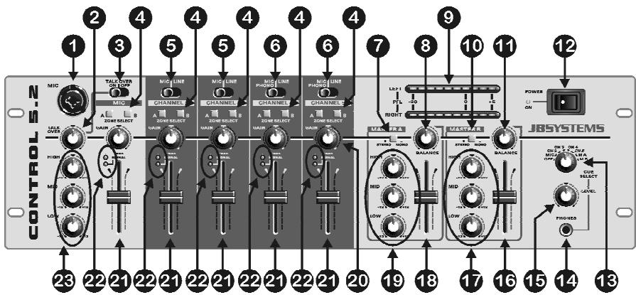
FRONT PANEL
-
DJ MICRO input: The DJ micro can be connected to the XLR/Jack input on the front plate or to the stereo jack on rear panel. This input is balanced but accepts any kind of microphone equipped with an XLR or jack connector.
-
TALKOVER level: When you switch the talkover(3) on, you can adjust the amount of muted on input channels 2 to 5. The more you turn to the right, the more these channels are muted while talking through the DJ Micro(1).
-
TALKOVER switch: Use this switch to automatically mute the input channels 2 to 5 while you are talking through the DJ microphone. Use the zone selectors(4) to choose on which output the talkover should work.
Attention: the talkover will only work on the zone you selected for the DJ Micro. The other zone won't be affected.
- ZONE switch: for every input channel you can choose to which zone (master) it should be routed. This means that you can use this mixer to serve two different rooms with completely different music!
Example:
You want channels 2&3 to be routed to Master A (room1). Channels 4&5 must be routed to Master B (room2). But you want to be able to make announcements in both rooms. This is what you should do:
- Select "zone A" on channels 2&3
- Select "zone B" on channels 4&5
- Select "zone A" and "zone B" on DJ Micro input.
Now you can do announcements in both rooms, while the music you play in both rooms is completely different.
-
INPUT SELECTOR switch: On channels 2 and 3 you can choose between line or balanced micro inputs.
-
INPUT SELECTOR switch: On channels 4 and 5 you can choose between line or balanced micro inputs but you can also connect a turntable. (line/phono switch on the back)
-
MONO/STEREO switch: used to switch Master A in mono or stereo mode.
-
BALANCE: used to adjust the balance between left and right output on Master A.
-
VU-meters: Used to monitor the level of the audio signals selected with the CUE selector(13). With the channel faders you can change the input level of each connected audio source. Make sure the levels do not exceed 0dB (or 100% ). The audio risks to be distorted when the signal level comes in the red zone of the VU-meter.
-
MONO/STEREO switch: used to switch Master B in mono or stereo mode.
11.BALANCE: used to adjust the balance between left and right output on Master B.
- POWER switch: Used to turn the power of the mixer on and off.
13.CUE SELECTOR switch: Used to select the source you want to monitor. You can listen to any input channel while its channel fader is closed.
14.CUE LEVEL: Used to control the output level of the headphone output.
-
HEADPHONE jack: You can connect any modern stereo headphone to this 6.3mm jack. Together with the cue selector (13) and the cue level (14) you can use it to listen to the selected input channel.
-
MASTER B level: Used to adjust the output level of Master B.
17.3BAND TONE control: use these 3 controls to modify the audio signal of Master B to your personal taste.
18.MASTER A level: Used to adjust the output level of Master A.
19.3BAND TONE control: use these 3 controls to modify the audio signal of Master A to your personal taste.
- GAIN controls: Used to set the sensitivity of each channel separately. Based on the information from the VU meters(9) and the peak led(22) you can adjust the channel sensitivity.
21.CHANNEL FADERS: Used to set the level of each channel separately.
-
PEAK & SIGNAL LEDs: all channels are equipped with a peak and signal led:
-
Signal led: The green signal led indicates that a music signal is present at this channel input.
- Peak led: The red peak led indicates that the input signal is too high. Make sure that the peak led only turns on from time to time. When the peak led is on for longer periods, you are urged to lower the input signal using the GAIN control(20).
23.3BAND TONE control: you can use these 3 controls to modify the audio signal of the DJ micro to your personal taste or to remove feedback from the microphone.
Note: Feedback is where an acoustic signal is amplified over and over again until it develops rapidly into a loud screech: Reduce the gain on your microphone channel and/or try cutting HF from your tone controls.
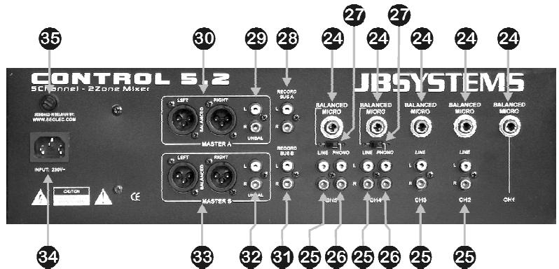
REAR PANEL
- DJ MICRO input: Used to connect a balanced (stereo jack) or unbalanced (mono jack) micro to this channel.
25 LINE input: Used to connect any line level sound source to this channel. - PHONO input: Used to connect a turntable to this channel.
- PHONO/LINE switch: Used to select either the phono input(26) or microphone input(24) on channels 4 and 5.
- RECORD BUS A: line level output with the signals from channels 2 to 5. Only the channels where you selected zone A will be on this output.
Important note: the tone controls, DJ microphone and talkover function are NOT available on this output. This means that the DJ can talk as much as he wants; on this output only the music will be recorded.
- MASTER A unbalanced output: Used to connect an amplifier with unbalanced inputs. The output level can be set by the MASTER A level (18).
- MASTER A balanced output: Used to connect an amplifier with balanced inputs. The output level can be set by the MASTER A level (18).
- RECORD BUS B: line level output with the signals from channels 2 to 5. Only the channels where you selected zone B will be on this output.
Important note: the tone controls, DJ microphone and talkover function are NOT available on this output. This means that the DJ can talk as much as he wants; on this output only the music will be recorded.
- MASTER B unbalanced output: Used to connect an amplifier with unbalanced inputs. The output level can be set by the MASTER B level (16).
- MASTER B balanced output: Used to connect an amplifier with balanced inputs. The output level can be set by the MASTER B level (16).
- MAINS INPUT: connect the supplied mains cable to a 230V/50Hz mains outlet. Before use, inspect the cable to be sure it's not damaged!
- MAIN FUSE: The main fuse protects the mixer. Replace it only with the same type and value.
SPECIFICATIONS
Power Supply: AC 230 V, 50Hz
Fuse: 20mm glass fuse 250V 500mA slow
Frequency response: 20-20.000Hz (+/-2dB)
THD + noise: <0.1% @ 1kHz, 0dB
Micro inputs: 1.5mV @ 10kΩ
Line/CD inputs: 150mV @ 22kΩ
Phono inputs: 3mV @ 47kΩ
Record output: 775mV @ 600Ω
Master A/B output: 1.5V @ 4k7Ω unbal.
Master A/B output: 850mV @ 600Ω bal.
Talkover: 0dB → -15dB
Tone controls: +/-12dB @ 10kHz / 1kHz / 100Hz
Headphone: 1V@33Ω
Dimensions: 483(W) x 134(H) x 130(D) mm
Weight: 2kg
MODE D'EMPLOI
CHARACTERISTIQUES
1.5V @ 4k7Ω s/balance
Saïda Master A/B:
850mV @ 600Ω balanceada
Talkover:
0dB -15dB
270(L)x180(A)x45(D)mm
Peso:
2Kg