440T - Laptop MAXDATA - Free user manual and instructions
Find the device manual for free 440T MAXDATA in PDF.
User questions about 440T MAXDATA
0 question about this device. Answer the ones you know or ask your own.
Ask a new question about this device
Download the instructions for your Laptop in PDF format for free! Find your manual 440T - MAXDATA and take your electronic device back in hand. On this page are published all the documents necessary for the use of your device. 440T by MAXDATA.
USER MANUAL 440T MAXDATA
Suspend-to-Disk 2-11
LPT Extended Mode 5-7
Main Advanced Security Power Exit
Peripheral and Memory
Floppy Drive A = 1.44 Mb, 3^1/2 Hard Drive 0 = 2167 MB
Hard Drive 1 = Disabled
COM 1/COM 2 = RS-232 /Disabled
LPT Port = LPT1, Addr 378 IRQ 7
Base = 640 KB
Extended = 31744 KB
Shadow = 64 KB
Reserved = 320 KB
Total RAM = 33824 KB
Cache (Ext) = 0 KB
Max Performance
Balanced Power Saving
Max Power Saving
Customize
Intel® SpeedStep™ Tech.
Balanced Power Saving
Max Power Saving
Customize
Cover Close (Deckel schlieben)
Save Change and Exit
Discard Changes & Exit
Get Default Values
Load Previous Values
Beschreibung
Suspend-to-Disk, 2-11
Hotkeys, 2-7
Hotkey festlegen, 5-13
manuell aktivieren, 2-10
This chapter introduces the outstanding features of the notebook and tells you how to get the notebook up and running.
Features
Congratulations on purchasing your new notebook. Your notebook incorporates advanced capabilities which allow you to boost up your performance in the world of multimedia. Among the powerful features are:
Intel Pentium III, Pentium II or Celeron series microprocessor
Your notebook is equipped with one of the most advanced central processor making it ready for excellent performance.
NOTE: For the latest information on the motherboard and CPU installed in your notebook, please ask your dealer for assistance.
Built-in PCI audio system
With your notebook's PCI audio capabilities, you can experience fantastic 3D audio sensations and realistic acoustic effects.
- PCMCIA slots with CardBus and ZV port support
CardBus and ZV port standards satisfy the need for high-speed data transmission, such as full-motion video, video capture, and networking.
- IR port support
With the IR port, wireless communications are possible between your notebook and an IR device. The device is compliant with IrDA1.0, IrDA1.1 and ASK infrared interface standards.
USB port support
The Universal Serial Bus provides you the benefits of having one interface for multiple purposes when low-to-medium speed peripherals are concerned.
Advanced Power Management
You can conserve power automatically or manually by setting up the Power Management capabilities of your notebook.
Modem Card (optional, available in certain areas only)
A Fax/Modem/Voice card allows your notebook to be connected to a normal telephone line.
BIOS (Basic Input/Output System) that supports the years beyond 2000 AC
Other basic components of your notebook system are:
3.5-inch, 1.44MB (Megabytes) floppy disk drive
- ATA3 IDE hard disk drive, Ultra DMA/33 supported
- CD-ROM drive
- Two SO-DIMM sockets providing up to 256MB SDRAM upgrade capability (depending on the availability of SO-DIMM modules)
128/256/512KB on-die or L2 module cache memory, depending on CPU types
8MB video RAM
TFT LCD (Liquid Crystal Display) with XGA/SVGA resolution
Notebook keyboard
- Touchpad pointing device
- Track point device (select models only)
- Microphone and stereo speaker set
I/O connectors for external expansion
AC adapter
- NiMH or Li-ion rechargeable battery pack
Taking a Look at the Notebook
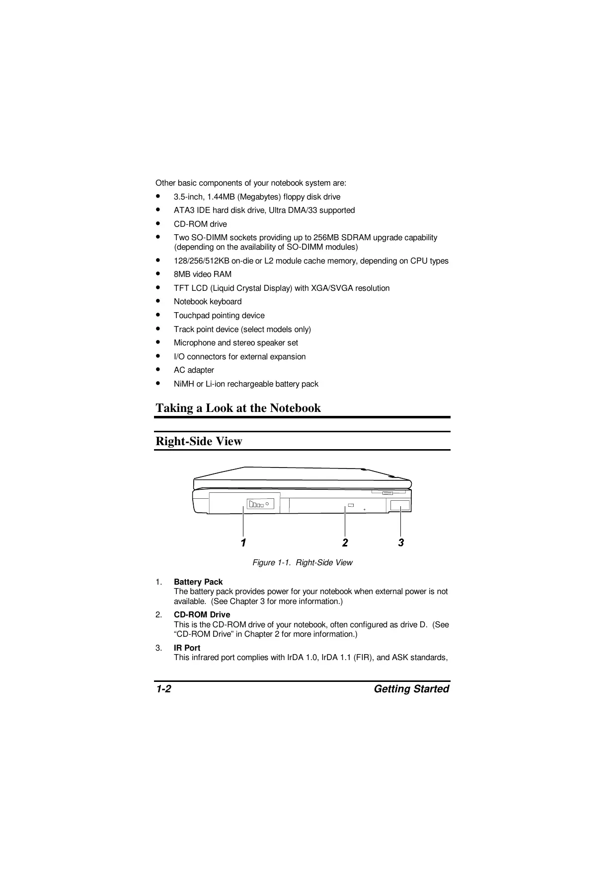
Right-Side View
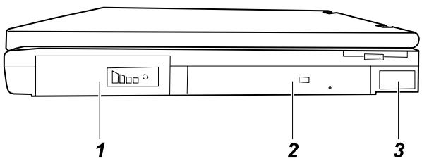
Figure 1-1. Right-Side View
- Battery Pack
The battery pack provides power for your notebook when external power is not available. (See Chapter 3 for more information.)
- CD-ROM Drive
This is the CD-ROM drive of your notebook, often configured as drive D. (See "CD-ROM Drive" in Chapter 2 for more information.)
- IR Port
This infrared port complies with IrDA 1.0, IrDA 1.1 (FIR), and ASK standards,
Left-Side View
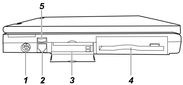
Figure 1-2. Left-Side View
1. S-Video Output Connector (→)
This can be connected to an external video device such as a TV with a S-video connector.
2. RJ-11 Connector ( ) (optional)
With the RJ-11 connector (exists when a Modem card is installed), the normal telephone line can be connected to your notebook.
3. PC Card Slots (
Each of the two PC card slots is for installing a PC card, or called PCMCIA card. The upper slot is Slot 0 and the lower Slot 1. (See "Installing a PC Card" in Chapter 4 for more information.)
4. Floppy Disk Drive
This is your notebook's 3.5-inch floppy disk drive, often referred as drive A. (See "Floppy Disk Drive" in Chapter 2 for more information.)
5. Volume Control (
This controls the volume of the sound coming from the notebook.
Rear View
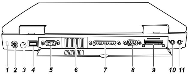
Figure 1-3. Rear View
- Kensington Lock Anchor ( )
This rectangular hole can be used as an anchor point for a Kensington-type security cable. You can use this cable to lock your notebook to an appropriate location for security.
- PS/2 Mouse/Keyboard Port (
This 6-pin mini-DIN port is for connecting a PS/2 keyboard or mouse.
This is for connecting the AC adapter.
- USB Port ( )
The 4-pin Universal Serial Bus port is for connecting an USB device. (See "Connecting an USB Device" in Chapter 4 for more information.)
- Serial Port (IOIOI)
This 9-pin port is for connecting a serial device such as a serial mouse, modem, or printer. (See "Connecting a Serial or Parallel Device" in Chapter 4 for more information.)
- Ventilation Opening
This is the opening for ventilation purpose.
- Parallel Port ( )
This 25-pin port is for connecting a parallel device such as a parallel printer or pocket LAN. (See "Connecting a Serial or Parallel Device" in Chapter 4 for more information.)
- VGA Port (
This 15-pin analog port is for connecting an external monitor.
- Expansion Connector (
This connector is for connecting the optional Port Replicator.
10. Microphone Connector

This can be connected to an external microphone for use in place of the notebook's built-in microphone.
11. Audio Output Connector ( ()
This can be connected to a set of headphones, external speakers with amplifier or an audio recording device.
Front View
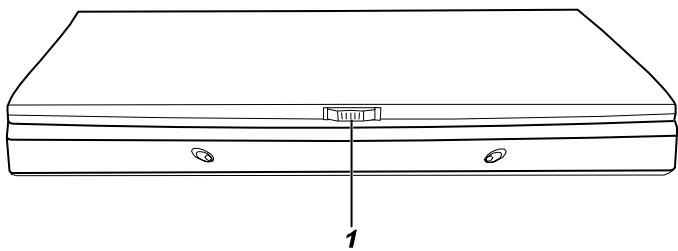
Figure 1-4. Front View
1. Top Cover Latch
This cover latch keeps the top cover firmly closed.
Bottom View
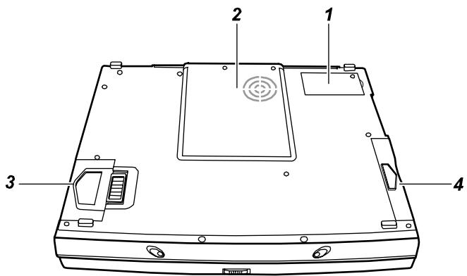
Figure 1-5. Bottom View
1. Modem Card/LAN Card Cover
Inside this cover is the Fax/Modem/Voice card or LAN card which allows your notebook to be connected to a network environment.
2. CPU Card Cover
Inside this cover is the CPU card and cooling fan system.
CAUTION: Do not cover or block the ventilation openings. For example, do not place the notebook on a bed, sofa, rug, or other similar surface. Otherwise, overheating may occur and result in damage to the notebook.
3. Battery Pack & Locking Latch
The locking latch prevents the battery pack from slipping out of the compartment.
4. FDD/HDD Module
This is the FDD/HDD module which plays a main character in data storage.
Top-Open View
To open the cover, press the cover latch toward the right and then lift the cover.
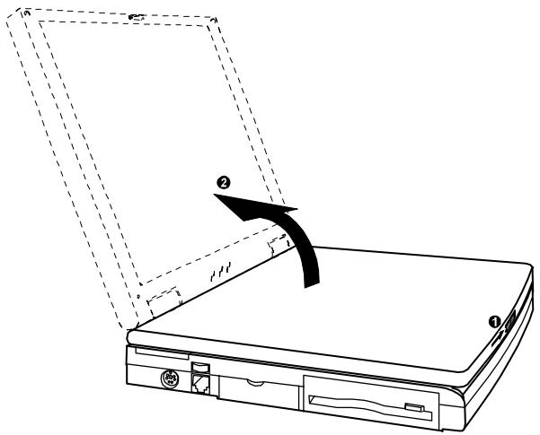
Figure 1-6. Opening the Cover
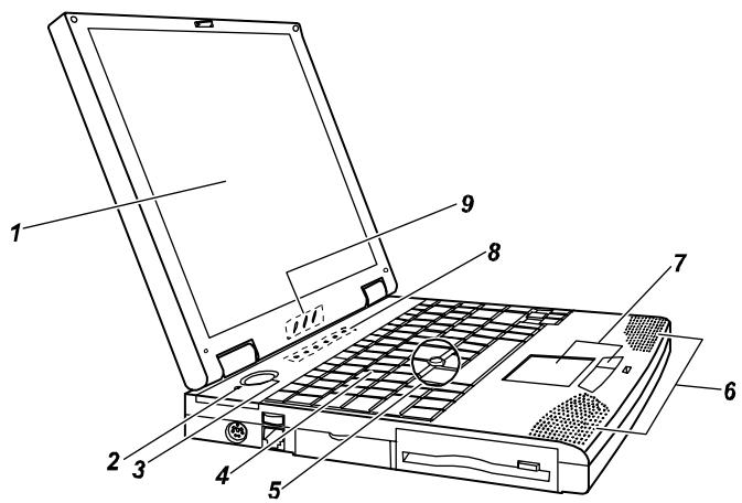
Figure 1-7. Top-Open View
1. LCD Display
This is the liquid crystal display of your notebook.
CAUTION: Do not place heavy objects on top of the notebook when it is closed as this can damage the display.
2. Microphone

This is the built-in microphone of your notebook.
NOTE: When using the microphone, make sure you lower the volume of the speaker to avoid noise caused by oscillation.
3. Power Button ( ① )
Pressing this button will turn the notebook power ON or OFF.
4. Keyboard
This keyboard provides all the functions of a full-size 101/102-key keyboard.
(See "Keyboard" in Chapter 2 for information.)
5. Track Point
This is the track point of your notebook (available on certain models only).
6. Stereo Speaker Set
This is the built-in speaker set of your notebook.
7. Touchpad
This is the pointing device of your notebook.
8. System Indicators
These are the indicators showing the status of system operation.
From right to left are:
Scroll Lock Indicator glows when you press the Scroll Lock key to activate Scroll Lock.
A Caps Lock Indicator glows when you press the Caps Lock key to activate Caps Lock.
1 Num Lock Indicator glows when you press the Num Lock key to activate Num Lock.
Floppy Disk Drive In-use Indicator glows when the notebook is accessing the floppy disk drive.
Hard Disk Drive In-use Indicator glows when the notebook is accessing the hard disk drive.
CD-ROM Drive In-use Indicator glows when the notebook is accessing the CD-ROM drive.
9. Power Indicators
These are the indicators showing the status of power conditions.
From right to left are:
+ Battery Condition Indicator
- Glows green when the battery is fully charged with AC adapter connected.
- Glows orange when the battery is being charged.
- Glows red when the battery charge is low.
- Blinks red when the battery charge is critical.
Battery Power Indicator
- Glows when the notebook is using battery power.
- Blinks when the notebook, using battery power, is in Suspend-to-RAM mode. (See "Introducing Power Management" in Chapter 2 for information on Suspend-to-RAM mode.)
AC Power Indicator
- Glows when the notebook is using AC power.
- Blinks when the notebook, using AC power, is in Suspend-to-RAM mode. (See "Introducing Power Management" in Chapter 2 for information on Suspend-to-RAM mode.)
Getting the Notebook Running
Connecting to AC Power
- Plug the DC cord of the AC adapter to the power connector on the rear of the notebook.
- Plug the female end of the AC cord to the AC adapter and the male end an electrical outlet.
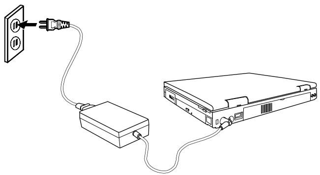
Figure 1-8. Connecting the AC Adapter
When the AC adapter is connected as shown above, the indicator on the AC adapter lights up, indicating that power is being supplied from the electrical outlet to the AC adapter and onto your notebook. When the Battery Condition Indicator ( ) on the notebook glows orange, it means that the AC adapter is fast-charging the battery.
- To fully charge the battery, leave the notebook power off, and wait for the Battery Charge Indicator to glow green.
CAUTION: Whenever you disconnect the AC adapter, always unplug from the electrical outlet first before you unplug from the notebook. A reverse procedure may damage the AC adapter or notebook.
When the AC adapter is not connected, you can operate the notebook using battery power only.
Using Battery Power
When the AC adapter is not connected, you can use battery power. To assure optimum battery life, fully charge and discharge the battery at least once and then fully charge the battery before you first use battery power. (For more information on using battery power, see Chapter 3.)
Starting Up
A computer starts up with an operating system existing on the hard disk (drive C) or a system diskette inserted into the floppy disk drive (drive A). The computer will automatically load the operating system after you turn it on. This process is called booting.
The notebook comes to you ready for use. This means the hard disk is pre-formatted and contains the files necessary for booting.
-
Open the top cover by pressing the cover latch toward the right and lifting up the cover.
-
Turn on the notebook by pressing the Power Button (Figure 1-7 #3).
-
Tilt the cover forward or backward to a comfortable viewing position. You can also adjust the brightness of the display to attain display clarity. Press [Fn]+[F6] to decrease the brightness or press [Fn]+[F7] to make the display lighter.
-
Each time the notebook is turned on, it performs a Power-On Self Test (POST). This checks the status of major computer devices including the system board, memory, video, keyboard, and disk drive. Some status messages from POST will appear on the screen.
If the POST has detected a mismatch between the actual hardware configuration and the configuration information stored in CMOS RAM, you will see error message(s) telling you to run the SCU program. The SCU program allows you to enter the configuration information and store it in CMOS RAM. The configuration information is needed by the notebook to identify the installed devices. Under SCU, you can also activate certain features such as Power Saving and Security. (See Chapter 5 for instructions on running SCU.)
- When POST successfully completes its check, the notebook first tries to boot from drive A or C depending on the "Boot Sequence" setting in the SCU program.
NOTE: To avoid viruses brought in by diskettes, it is advised that you boot the system from the hard disk instead of a diskette. If you must boot up from drive A, make sure the booting diskette is clean.
Installing Software
A CD is supplied with your notebook that contains software drivers you need to install for using the special features of your notebook. (See Chapter 6 for information on the drivers.)
Turning Off the Notebook
CAUTION: Do not remove the diskette or turn off the notebook when the Disk Drive In-use Indicator is on, as it may cause data loss on your disk.
- If you are using a program, save your data and exit the program.
- Remove the diskette, if any, from the drive.
- If you are using an operating system such as Windows 95 or Windows 98 that has the "Shut Down" command, simply select the command and the computer will turn off automatically.
Otherwise, turn off the notebook by pressing the Power Button. - Turn off the power of all connected peripheral devices.
- To close the top cover, tilt down the cover until the cover latch clicks into place.
CAUTION: If you have to turn the notebook on again immediately after turning it off, wait for at least five seconds. Turning the notebook off and on rapidly may damage the system circuit.
- When disconnecting the AC adapter, always unplug from the electrical outlet first.
Chapter 2
Using the Notebook
This chapter gives operating basics on the notebook's components such as the floppy disk drive, hard disk drive, CD-ROM drive, keyboard, and touchpad. It also introduces Power Management and gives you tips in care and maintenance.
Floppy Disk Drive
Your notebook comes with a floppy disk drive designated as drive A. A floppy disk drive allows you to load new programs into your computer, or to store data on a removable diskette so you can transfer data from one computer to another.
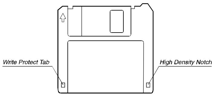
Figure 2-1. 3.5-inch Diskette
The floppy disk drive is compatible with either double-density (2DD) 720KB diskettes or high-density (2HD) 1.44MB diskettes. Notice that both types of diskettes have an arrow imprinted on the front upper left corner, and a slidable write-protect tab on the bottom left corner, as illustrated above. When slid downward, the write-protect tab prevents data from being written to, or erased from, the diskette.
Inserting and Ejecting Diskettes
To insert a diskette, hold it with the arrow facing up and towards the drive. Slide the disk into the drive until it clicks into place.
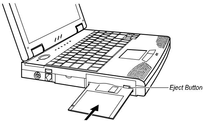
Figure 2-2. Inserting a Diskette
To eject a diskette, first make sure that the floppy disk drive in-use indicator is off, and then press the eject button on the drive. When the diskette pops out of the drive, remove the diskette and store it properly.
Formatting Diskettes
A diskette must be formatted before it can store any data. For information on how to format a diskette, please consult your operating system manual.
CAUTION:
- Never turn off or reset the notebook while the floppy disk drive in-use indicator is on.
- Always store your diskettes in a safe, clean container, protecting them from dust and magnetic fields.
Hard Disk Drive
Your notebook comes with a hard disk drive designated as drive C. A hard disk drive, also called a fixed disk, is a storage device with non-removable, rotating, magnetic storage platters. Compared with a diskette, a hard disk can retrieve and record data much faster and has a much larger storage capacity.
Your hard disk drive is a 2.5-inch IDE (Integrated Drive Electronics) hard disk drive. This type of drive utilizes the latest technology in fast, reliable mass storage by integrating directly onto the drive all the control circuitry necessary for operation. This allows the drive manufacturer to carefully optimize the drive performance.
CAUTION:
- To avoid unexpected data loss caused by viruses or accidents, please make regular backups of your files from the hard disk to diskettes.
- Never turn off or reset the notebook while the hard disk drive in-use indicator is on. In addition to possible data loss, the system and the hard disk drive's sensitive circuitry may be damaged.
CD-ROM Drive
Your notebook comes with a CD-ROM drive. A CD-ROM drive utilizes removable 5.25-inch compact disks which look like standard music CDs. The compact disk is an ideal medium for data storage or multimedia program because of its huge amount of data capacity.
Inserting/Removing a CD
CAUTION:
- When inserting a CD, do not push the CD-ROM drive harshly.
- Make sure the CD is correctly inserted into the tray, then close the tray.
- Do not leave the CD tray open. Moreover, avoid touching the lens in the tray with your hand. If the lens becomes dirty, the CD-ROM may malfunction.
- Do not wipe the lens with rough surfaced materials (such as paper towels). Instead, use a cotton swab to wipe the lens gently.
FDA regulations require the following statement for all laser-based devices: "Caution, Use of controls or adjustments or performance of procedures other than those specified herein may result in hazardous radiation exposure."
Follow this procedure to insert or remove a CD.
- Turn on the computer.
- Push the eject button (see Figure 2-3) and the CD tray will slide out. If the tray only slides out partially, gently pull it until fully extended.
- To insert a CD, place the CD in the tray with its label facing up.
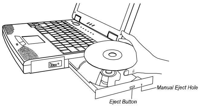
Figure 2-3. Inserting a CD
To remove a CD, hold the CD by its outer edge and lift it up from the tray.
- Slide the tray back into the drive bay.
Manually Releasing a CD
In the unlikely event that you are unable to release the CD tray by pressing the eject button, you can manually release the CD as follows:
- Turn off the system.
- Insert a small rod into the manual eject hole (see Figure 2-3) and push firmly to release the tray.
- Pull the tray out until the tray is fully extended, then remove the CD.
Keyboard
Your notebook keyboard has all the functions of a standard AT-enhanced keyboard plus some keys specific to your notebook.
Fn Key
The [Fn] key, at the lower left corner of the keyboard, is used with other keys to activate alternative functions, such as [Num Lock] and [Scroll Lock].
Typewriter Keys
Typewriter keys are similar to the keys on a typewriter. Several keys are added such as the [Ctrl], [Alt], [Esc], and lock keys for special purposes. When the lock keys are pressed, their corresponding indicators will light up.
Num Lock]
Pressing this key toggles the Num Lock on and off. When on, the Num Lock activates the numeric keys.
- [Scroll Lock]
Pressing this key toggles Scroll Lock on and off. The Scroll Lock is defined by individual programs.
[Caps Lock]
Pressing this key toggles the Caps Lock on and off. When on, the Caps Lock keeps the letter keys in uppercase.
NOTE:
If your Windows 95/98/NT system supports the Euro dollar sign (), you can press the sign on a standard US or UK keyboard:
For a standard US keyboard, hold down either of the [Alt] keys and type 0128 on the numeric keypad of your keyboard.
For a standard UK keyboard, hold down the [AltGr] key (or the [Alt] key on the right side) and press the number key 4.
Function Keys
On the top row of the keyboard are the function keys: [F1] to [F12]. Function keys are multi-purpose keys which perform functions defined by individual programs.
Hot key functions are assigned to [Fn]+[F5] through [Fn]+[F12] by your notebook. (See „Hot Keys" later in this chapter for information.)
Cursor-Control Keys
At the lower right corner of the keyboard are four cursor-control keys: [] , [] , [] , and [] . These keys, also called arrow keys, control cursor movement.
On the right side of the keyboard are [Home], [PgUp], [PgDn], and [End] keys, which control the screen or cursor movement.
Left to the arrow keys are the [Ins] and [Del] keys used for editing purposes.
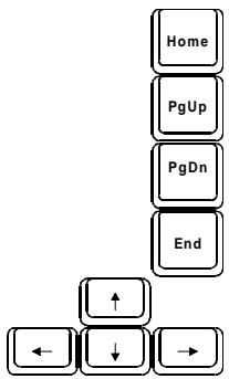
Figure 2-4. Cursor-Control Keys
Numeric Keypad
A 15-key numeric keypad is embedded in the typewriter keys as shown below:
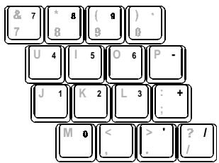
Figure 2-5. Numeric Keypad
Numeric keys facilitate entering of numbers and calculations. When Num Lock is on, the numeric keys are activated, meaning you can use these keys to enter numerals.
NOTE:
- When the numeric keypad is activated and you need to type the English letter, you can either turn Num Lock off or hold down [FN] and press the key without turning Num Lock off.
- If the „Keyboard Numlock“ item in the SCU program is set to Disabled, you can not directly use the numeric keypad on the notebook keyboard even if Num Lock is on. To use the numeric keys in this case, you can hold down [FN] key first.
- Some software may not be able to use the numeric keypad on the notebook. If so, use the numeric keypad on an external keyboard instead.
Windows 95 Keys
On the Windows 95 keyboard, you can find one Windows Logo key ( ) and one Application Logo key ( ). The two keys are used with other keys to perform software-specific functions. (See your Windows 95 manual.)
Hot Keys
Hot keys refer to a combination of keys that can be pressed at any time to activate special functions. Most hot keys operate in a cyclic way. Each time a hot key sequence is pressed, it shifts the corresponding function to the other or next choice.
You can easily identify the hot keys with the icons printed on the keytop. The hot keys are described below.
Fn F5 toggles between video display output (in sequence: LCD CRT LCD&CRT CRT&TV TV).
F6 decrease LCD brightness.
Fn F7 increase LCD brightness.
Fn F8 reserved.
Fn F9 reserved.
Fn F10 toggles between Battery Low Warning beep on and off. Note that this disables the function temporarily without changing the "Battery Low Warning Beep" setting in the SCU program.
Fn F11 toggles the LCD panel on and off.
Fn F12 activates the „Suspend-to- RAM^ or „Suspend-to-Disk" mode according to the setting of SCU.
Touchpad
Your notebook integrates a touchpad pointing device, compatible with the Microsoft Mouse and IBM PS/2 mouse, which allows you to take advantage of software that requires or recognizes a pointing device.
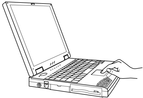
Figure 2-6. The Touchpad
Using the Touchpad
Placing and Moving the Finger
To use the touchpad, place your thumb or forefinger on the touchpad. The rectangular pad acts like a miniature duplicate of your display. As you slide your fingertip across the pad, the pointer, or cursor, on the screen moves in the same direction across the screen as your fingertip moves across the pad.
Point and Click
When you have placed the cursor over the icon, menu item or command that you wish to execute, you can press the left button once or twice to execute the command. This procedure is called "Point and click" or "point and double-click". On the touchpad, you can execute point and clicking even more rapidly. Instead of clicking by pressing the left button, you can just tap gently anywhere on the rectangular pad of the touchpad. Tap twice rapidly to execute a double-click. Unlike a traditionally pointing device, the whole pad acts as if it were a left button and each tap on the pad is equivalent to pressing the left button.
NOTE: If you swap the left and right buttons, "tapping" on the touchpad as an alternative method of pressing the left button will no longer be valid.
Drag and Drop
You can execute commands or move files by using „drag and drop“. In drag and drop, you activate a file by pointing to it and clicking. However, when you click the button, you do not release the button but instead hold it down. You can then drag the active file around the screen by moving your finger around the pad. When you have placed the file where you want it, for example in a new directory, release the left button. The file will drop into the new location. You can also do drag and drop operations using the touchpad as a large left button. Position the cursor over the item that you want to drag. Gently tap twice on the pad. On the second tap, keep your finger in contact with the pad. You can then drag the selected object around the screen by moving your fingertip across the pad. When you lift your fingertip from the pad, the selected object will drop into place.
Changing the Configuration
You may want to customize the mouse. For example, if you are a left-handed user, you can swap the buttons over so that you can use the right button to generate events that are normally generated by the left button. You can also change the size of the on-screen pointer, the speed of the pointer and so on.
If you are using Windows, double-click the „Mouse“ icon in the Windows Control Panel. The Mouse Properties window allows you to change various configurations. Instead of Windows, you can also use the touchpad software supplied with your notebook to change the configuration.
Introducing Power Management
The Power Management feature of your notebook helps conserve power. The followings briefly describe the features. To establish Power Management, run the SCU program. (See „Power Menu" in Chapter 5 for instructions.)
Automatic Power Management
Local Power Management
Local Power Management controls notebook subsystems. When a subsystem is inactive for a period of time, called „time-out“, it is automatically shut down or slowed down to reduce power consumption. The subsystem will be active again when next accessed.
The subsystem under power management is:
Hard Disk Drive
The hard disk drive powers down after the set time-out period.
Global Power Management
Global Power Management automatically puts the notebook into low-power mode when the notebook is inactive for a period of time, called „time-out.” The notebook will wake up whenever an activity is detected (e.g. pressing a key).
Global Power Management works in a three-stage manner following this order:
- Idle mode
- Standby mode
- Suspend mode (The notebook suspends to RAM or disk depending on the "Suspend Data to" setting in the SCU program.)
The time-out settings for these three modes takes effect in sequence. That is, if the notebook stays inactive for a long period of time, it will first turn into Idle mode, then Standby mode, and finally Suspend mode.
In the three modes above-mentioned, every subsequent mode saves more power than the previous one (Suspend>Standby>Idle).
Manual Power Management
You can manually initiate Suspend mode at any time in one of these ways:
- By pressing the hot key [Fn]+[F12].
- By closing the top cover. Note that this works only if the „Cover Close“ item is set to Suspend in the SCU program.
For information on Suspend-to-Disk mode, see the following section.
Suspend-to-Disk
CAUTION:
- The suspend-to-disk partition may not exist on your hard disk. Check with your dealer to know if it exists. If there is no suspend-to-disk partition, you can not use the Suspend-to-Disk feature.
- The 0VMAKFIL utility allows you to create the suspend-to-disk partition. (See „0VMAKFIL Utility" in Chapter 6 for information.)
When the notebook suspends to disk, the system preserves all the running application programs as a file in a „suspend-to-disk partition“ on the hard disk. The notebook then turns off automatically. When you next turn on the notebook, it reads the file from the suspend-to-disk partition back into memory, so that your notebook is returned to exactly the same state it was in when you suspended it.
Suspend-to-Disk is a very useful feature. People frequently open many applications when they use computers. It takes some time to get all these applications open and running, and normally they all have to be closed before the system can be turned off. If you use the Suspend-to-Disk feature, you don't have to close the applications as the state of your notebook is saved to disk. When you turn on your notebook next time, your notebook with all the applications open will be recreated in just a few seconds.
Taking Care of Your Notebook
Maintenance
- Avoid placing the notebook in a location subject to high humidity, extreme temperatures, mechanical vibration, direct sunlight, or heavy dust.
- Do not place heavy objects on top of the notebook when it is closed as this may damage the LCD.
- To assure smooth operation of the touchpad, occasionally clean the pad by using adhesive tape to remove the dust and grease on its surface.
- Occasionally clean the notebook with a soft cloth moistened with water. Do not use soap or liquid cleaners on the display.
- When the external connectors are not in use, keep their covers closed to prevent possible damage caused by dirt or static electricity.
Take care of the battery pack by following the instructions described in "Important Notes on Using Battery Pack" in Chapter 3.
Traveling
- Before traveling with your notebook, it would be a wise move to backup your hard disk data into diskettes. As a precautionary measure, bring along an extra copy of your hard disk data.
Make sure the battery pack is fully charged.
Make sure the notebook is turned off and the top cover is firmly closed. - Disconnect the AC adapter from the notebook, and take it with you. Use the AC adapter as the power source and as a battery-recharger.
- Allow extra time for airport security. Many airports inspect electronic devices carefully.
- Hand-carry the notebook. Do not check it in as luggage.
- If you plan to travel abroad with your notebook, consult your dealer for the appropriate AC power cord fitting the electricity standard of your destination.
Chapter 3
Battery Operations
This chapter tells you what you should know when using battery power. For optimal performance of the battery, be sure to follow the notes described in this chapter.
AC Adapter
CAUTION:
- The AC adapter is designed for use with your notebook only. Connecting the AC adapter to another device may damage it.
- The AC power cord supplied with your notebook is for use in the country where you purchased your notebook. If you plan to take the notebook overseas, consult your dealer for the appropriate power cord.
The AC adapter serves as a converter from AC (Alternating Current) to DC (Direct Current) power because your notebook runs on DC power, but an electrical outlet usually provides AC power. It operates on any voltage in the range of 100-240V AC.
The battery pack automatically recharges while your notebook is connected to AC power.
Battery Pack
The battery pack supplies power to your notebook when external power is not available. It is rechargeable using the AC adapter.
Recharging the Battery Pack
To recharge the battery pack, connect the AC adapter to the notebook and an electrical outlet. For NiMH batteries, it takes approximately two to three hours to fully charge a power-deleted battery pack when the notebook is power off. For Li-ion batteries, it takes approximately 90 minutes to charge the battery pack to 80% capacity and two or three more hours to fully charge the battery pack.
During recharging, the Battery Charge Indicator (+1-1) on the notebook glows orange. It is advised that you keep the notebook power off while the battery is being recharged. The battery is fully recharged when the Battery Charge Indicator glows green.
Knowing the Battery Charge
NOTE: The battery is made up of chemical material and its capacity cannot be measured physically. The only way of knowing the battery charge is by estimation. However, the estimation may get less accurate under some situations (for example, after a long period of storage or when using a new battery pack). If this happens, you can fully discharge and recharge the battery. Then, the Gas Gauge will work again.
By Operating System
While the notebook is in use, you can view the battery charge with some operating systems, e.g., Windows. Windows can display a battery meter that shows the battery charge.
By Gas Gauge
On the exterior side of the battery pack is a gas gauge for displaying the estimated battery charge. If the battery pack is not installed in the notebook and you want to know the battery charge, you can press the on/off switch with a pointed device to see the number of indicator segments that light green. The number of green segments indicates the relative percentage of the battery charge. The battery pack is fully discharged when you see no segment glowing green or one segment flashing green.
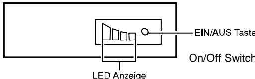
Figure 3-1. LED Indicators Battery Pack
NOTE:
- To ensure best performance of the battery, it is advised that you fully discharge and then recharge the battery before you use it for the first time.
- A rechargeable battery gets worn gradually as you use it. To djust the gas gauge according to the "battery wear", you can fully discharge and then recharge the battery after you use it for a period of time (say, one month). This will give the battery a learning cycle.
Replacing the Battery Pack
CAUTION: There is danger of explosion if the battery is incorrectly replaced. Replace the battery only with the notebook manufacturer's optional battery packs. Discard used batteries according to the dealer's instructions.
If you often use the battery power for a long period of time while traveling, you may consider the purchase of an additional battery pack from your dealer, and keep it with you in a fully charged state as a backup.
To replace the battery pack, follow these steps:
- Make sure the notebook is not turned on or connected to AC power.
- Carefully put the notebook upside down.
- Press the locking latch outward to unlatch the battery pack and then pull it out of the compartment.
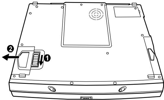
Figure 3-2. Removing the Battery Pack
- Replace the old battery with a new one. Insert the battery pack into the compartment and the latch will lock into position.
Important Notes on Using Battery Pack
Recharging and Discharging
-
Recharging will not start if the battery's temperature is below 0^ ( 320^ ) or above 400^ ( 1040^ ). Also, during recharging, the recharging will stop if the battery's temperature gets above 600^ ( 1400^ ). To avoid problems caused by temperatures, make sure the battery is not too hot before you begin to recharge or discharge the battery. Follow these general advises:
-
When the battery is fully discharged, allow a 30-minute interval before you connect the AC adapter to recharge the battery.
-
When the battery is being recharged, keep the notebook power off and wait until it is fully recharged.
-
When the battery is fully recharged, disconnect the AC adapter and allow a 30-minute interval before you begin to use the battery power.
-
During recharging, do not disconnect the AC adapter before the battery has been fully charged; otherwise you will get a prematurely charged battery.
After the notebook has been fully recharged, do not immediately disconnect and reconnect the AC adapter to charge it again. Doing so may damage the battery. - Do not leave the battery completely discharged for too long as this may affect the battery's performance.
Problem Solving
- If the actual operating time of the battery is much shorter than the expected operating time, you can fully discharge and recharge the battery for at least 3 times to solve the problem.
Operating and Handling
- Never remove the battery pack while it is in use. If you need to replace the battery pack, make sure you have turned off the notebook power.
- Leave the battery pack in place unless you will replace it. If you remove the battery pack, keep it away from conductors such as metals and water. In case the battery's pins get into touch with conductors, the battery may become unusable as a result of short-circuit.
- When you disconnect the AC adapter, disconnect from the electrical outlet first and then from the notebook.
- To prevent data loss that may be caused by low battery, develop the habit of frequently saving your data to the hard disk or a diskette.
- Do not attempt to disassemble the battery pack.
Maintaining
- When you install a new battery, fully charge and discharge the battery at least once and then fully charge the battery before you begin to use the battery power for the first time.
- Protect your notebook from extremes in temperature. (See "Environmental Specifications" in Appendix A for temperature range.)
- Do not store fully-charged battery packs in a bulky, densely packed condition, otherwise the overheating of the battery pack and subsequently the melting of the plastic case can happen.
Low Battery Signals and Actions
Low battery signals occur when the battery has approximately 10% of its charge remaining. The notebook gives warning beeps and the Battery Charge Indicator (+7) blinks red to alert you to take actions.
Immediately save your data upon the Low Battery warning. The remaining operating time depends on how you are using the notebook: if you are using the audio subsystem, PC card, hard or floppy disk drives, the battery might run out of charge very quickly.
Always respond to the Low Battery warning by connecting the AC adapter or turning off the notebook, or suspending your notebook to disk.
If you do not take any action, after two minutes the notebook will automatically suspend to disk and turn off.
CAUTION:
- If the "Low Battery Warning Beep" item is disabled in the SCU program, the notebook will not beep.
- If the suspend-to-disk partition does not exist or the "Suspend-to-Disk" item is not set in the SCU, the notebook will not be able to suspend to disk. It will keep on beeping until you take actions or until the battery runs out of charge.
- If you are using a flash PC card, do not access the card during low battery periods. This is because the access may take longer than the time it takes the battery to run out of charge, thus making your access unsuccessful.
- If you fail to save your data when the battery completely runs out of charge, then you lose your data.
Chapter 4
System Expansion
This chapter introduces the optional devices for your notebook and tells you how to install some of the devices.
External Connections
I/O connectors on the notebook allow you to connect external devices to your notebook. See Figures 1-1 to 1-4 for connector locations and the descriptions that follow. This section provides notes on using some of the connectors.
Connecting an External Monitor
If you want the benefits of a larger color display screen, you can connect an external VGA-compatible CRT monitor to your notebook. Follow these steps to connect a monitor to your notebook:
- Make sure that your monitor is configured for analog operation and that the voltage setting corresponds to that of the electrical outlet. Consult the monitor's manual for instructions.
- Make sure the notebook is not turned on or connected to AC power.
- Open the cover on the rear of the notebook. Plug the monitor's D-type signal connector to the notebook's VGA port, marked as (Figure 1-3 #7).
- Plug one end of the monitor's power cord into the power socket on the monitor and the other end to an electrical outlet.
- To use the monitor, turn on the monitor before turning on the notebook.
- The monitor should respond by default. If not, you can switch the display to the monitor by pressing [Fn]+[F5].
Supplied with your notebook are several video utilities and drivers which offer extended video modes. See Chapter 6 for more information.
Connecting an External Keyboard
If you want the benefits of a full-size keyboard, you can connect a PS/2-compatible keyboard to your notebook. Just plug the keyboard cable to the PS/2
mouse/keyboard port, marked as (Figure 1-3 #2) on the rear of the notebook, and the notebook will automatically recognize the external keyboard. The external keyboard and notebook keyboard can be used at the same time.
Connecting a Mouse
If you want the benefits of an external mouse, you can connect a PS/2-compatible mouse or serial mouse to your notebook.
For a PS/2 mouse, plug the mouse cable to the PS/2 mouse/keyboard port, marked as (Figure 1-3 #2) on the rear of the notebook.
For a serial mouse, follow these steps to make the connection:
- Turn off the power of your notebook.
- Plug the mouse cable to the serial port, marked as [IOIO] (Figure 1-3 #5) on the rear side of the notebook.
- Make sure the "COM Port" item is set properly in the SCU program. (See "Advanced Menu" in Chapter 5 for information.)
When an external mouse is connected, the internal touchpad is automatically disabled.
Connecting a Serial or Parallel Device
On the rear of the notebook, you can find a serial port (COM1), marked as [IOIO], and a parallel port, marked as . You can connect a serial device such as a serial mouse or modem, or a parallel device such as parallel printer, respectively.
In addition to following the instructions supplied with the device, take note of the following:
- To use a serial device, make sure the "COM Port" item is set properly in the SCU program. (See "Advanced Menu" in Chapter 5 for information.)
- To use a bi-directional or ECP/EPP-compliant parallel device, make sure that the "LPT Extended Mode" item is set accordingly in the SCU program. (See "Advanced Menu" in Chapter 5 for information.)
- Portable modems which are powered by serial or parallel ports cannot be used with your notebook. Instead, use a modem which is powered by its own internal battery or external AC power.
Connecting an IR Device
The IR port (Figure 1-1 #3) on the right side of the notebook allows you to connect an IR device for wireless communications.
In addition to following the instructions supplied with the device, take note of the following:
- The IR port of the device to be connected must face the IR port of the notebook within the effective range, i.e. within ± 15 -degrees angle and 1-meter distance.
-
Make sure the "COM Port" and "Ir Mode" items are set properly in the SCU program. (See "Advanced Menu" in Chapter 5 for information.)
-
If you are a Windows 98 user, you need to follow this procedure to enable the IR function: "Start Windows 98" "Control Panel" "Network" "IrDA V3.0 Fast Infrared Port" "Property" "Advanced" "Value" "HP2300".
To take advantage of the IR communications, you need third party software.
Connecting an USB Device
The USB port, marked as (Figure 1-3 #4) on the rear of the notebook, allows you to connect an USB device.
USB is specified to be an industry standard extension to the PC architecture. It features a wide range of applications such as multiple connections (i.e., support for concurrent operation of many devices) and compound devices (i.e., peripherals composed of many functions).
Follow the instructions supplied with the device.
Connecting TV/Audio Equipment
Connecting TV
- Make sure the notebook is not turned on or connected to AC power.
- You need a video cable for connection. Plug the connector of the video cable into the S-video Output connector, marked as (Figure 1-2 #1) on the left side of the notebook.
- Plug the other end of the cable into the video input connector of the TV.
- Turn on the notebook and run the SCU program. Set the "TV Mode" item to NTSC or PAL (PAL for standard in the UK and Europe). Save and exit the SCU program. The notebook will be restarted.
- Turn on the power of the TV and switch to the video mode.
Connecting Audio Equipment
You need an audio cable for the connection. See Figure 1-3 #9 and 10 for audio connector locations and the descriptions that follow.
Internal Installation
Installing a PC Card
PC cards, available in the market, provide various functions. Examples are memory cards, fax/modem cards, and LAN cards.
PC cards that conform to the PCMCIA 2.1 standard can be used with your notebook. Two advanced interfaces are also supported by the PC card slot: CardBus and ZV (Zoomed Video) port.
CardBus provides compatibility with 16-bit PC cards and extends performance and functionality by adding 32-bit data transfers, and by employing PCI (Peripheral Component Interconnect) concepts. Typical PC cards that utilize CardBus are graphic video, full-motion video, SCSI host bus, and high speed network cards. Typical PC cards that utilize the ZV port are MPEG and Video Capture cards.
Follow these steps to insert a PC card.
- Install the PCMCIA driver. (See Chapter 6.)
- Locate the PC card slots on the left side of the notebook. The upper slot is Slot 0 and the lower one Slot 1.
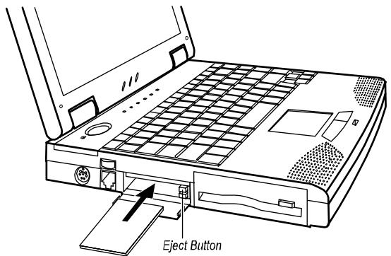
Figure 4-1. Installing a PC Card
- Slide the PC card with its label facing up into the slot until the eject button pops out. (To remove a PC card, press the corresponding eject button.)
For further instructions, please read the documentation supplied with your PC card.
Notebook Upgrade
You can upgrade your notebook by changing the CPU or adding memory for a maximum of 544/576MB (depending on the availability of SO-DIMM modules). If your notebook is not equipped with a Fax/Modem/Voice card or LAN card, you can have it installed. However, to avoid damage during the installation procedure, please ask your dealer for help. Do not install any component by yourself.
Chapter 5
Setup Configuration Utility
This chapter tells you how to configure your system using the SCU (Setup Configuration Utility).
Introduction
SCU allows you to configure the BIOS settings. Those settings are vital for your notebook to identify the types of installed devices as well as to utilize special features. Typical menu items include Date and Time, the types of disk drives, and the amount of memory. Special features include Power Saving and Security.
The settings information is stored in the CMOS (Complementary Metal Oxide Semiconductor) RAM, which is powered by a RTC backup battery.
You may need to run SCU when:
- You see an error message on the screen requesting you to run SCU.
- You want to restore the factory default settings.
You want to modify some specific settings.
Starting SCU
SCU is built into the system board. To run SCU, press [F2] during system startup. The main SCU screen appears as shown in Figure 5-1.
NOTE:
- The SCU screen shots shown in this chapter are for your reference only. The actual items on your notebook may differ.
- The SCU program may have been updated after the publication of this manual.
Main Advanced Security Power Exit Peripheral and Memory
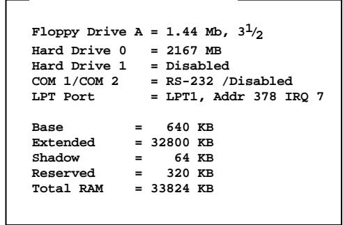
Figure 5-1. Main SCU Screen
Item Specific Help
The SCU screen can be divided into four areas:
- On the top line of the screen is the menu bar, which lists the titles of the available menus. Each menu title contains a pull-down menu, which displays items for settings.
- The left column on the screen displays current settings of the system. If you open a pull-down menu and select an item that provides multiple options, the left column will display a submenu where you can make further selections.
The right column on the screen provides details of the selected item. - The bottom part of the screen provides keyboard/mouse instructions for moving around and making selections.
Moving Around and Making Selections
You must go through two or three levels to complete the setting for an item. In most cases, there are three levels: menu title, pull-down menu, and submenu.
To move around and make selections, you can use both the touchpad/mouse and keyboard.
Using the Touchpad/Mouse
You are advised to use the touchpad or mouse. It is more straightforward than using the keyboard.
For most items, simply move the pointer with the touchpad/mouse and left-click on the intended item. To cancel your selection, click the right button. For some items, you will need to select with the arrow keys.
Using the Keyboard
Keyboard information can be found at the bottom of the screen. You can also use the shortcut key, which is highlighted in a different color on the screen.
Described below is the general procedure to complete a setting by use of the keyboard:
- Select a menu title with the left/right arrow key and press [Enter] to pull down the menu. You can directly pull down a menu by pressing the shortcut key.
- From the pull-down menu, select an item with the up/down arrow key and press [Enter] to access the submenu. You can directly access the submenu by pressing the shortcut key. The submenu displays the options you can select. If no submenu appears, simply press [Enter] to enable or disable the specific function.
- For most menu items, pressing the [Tab] key will jump from one item to another, thus allowing you to go through the items quickly. To confirm the changes you make, press [Enter] or select the OK button. To cancel the changes, press [Esc] or select the Cancel button.
Main Menu
The Main pull-down menu, as shown below, contains the basic configuration settings of the system.
Main
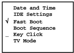
The followings describe in sequence all the items of the Main menu.
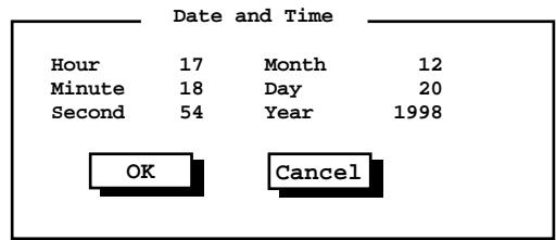
Date and Time
The "Date and Time" item sets the system date and time.
When this item is selected, the submenu will display as shown below.
IDE Settings
The "IDE Settings" item sets the type of the hard disk drive in your system.
When this item is selected, thesubmenu will display as shown below.
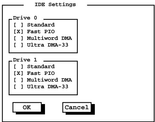
Drive 0 is the primary hard disk drive and Drive 1 the secondary.
Fast Boot
The "Fast Boot" item, when enabled, speeds up the booting procedure by bypassing the memory test.
When this item is selected, no submenu will display. A check mark () indicates Enabled; an underline (_) indicates Disabled.
The default setting is Enabled.
Boot Sequence
The "Boot Sequence" item sets the sequence of booting.
When this item is selected, the submenu will display as shown below.
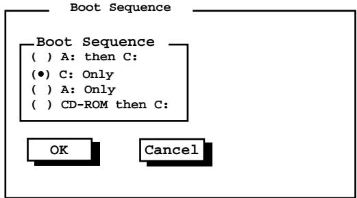
Descriptions of the available options are:
Options
A: then C:
Descriptions
The system will try to boot from drive A first. If a diskette with operating system does not exist, the system will then try to boot from drive C (hard disk).
C:Only
The system will try to boot from drive C (hard disk) only.
A:Only
The system will try to boot from drive A only.
CD-ROM then C:
The system will try to boot from the CD-ROM drive first. If a CD-ROM with operating system does not exist, the system will then try to boot from drive C (hard disk).
The default setting is C Only.
Key Click
The "Key Click" item sets if there will be a click sound whenever a key is pressed.
When this item is selected, no submenu will display. A check mark () indicates Enabled; an underline (_) indicates Disabled.
The default setting is Disabled.
TV Mode
The "TV Mode" item sets the TV mode when a TV is used for display output.
When this item is selected, the submenu will display as shown below.
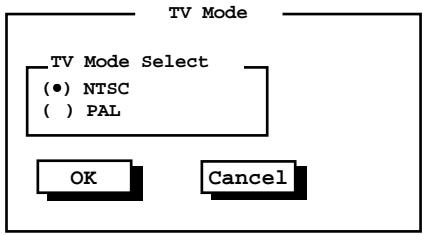
Select PAL for use in the UK and Europe; NTSC for use in other areas.
The default setting is NTSC.
Advanced Menu
The Advanced pull-down menu, as shown below, contains the I/O configuration settings of the system.
Advanced
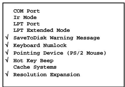
The followings describe in sequence all the items of the Advanced menu.
COM Port
The "COM Port" item allows you to assign COM1 and COM2 to specific functions that you wish to use. In general, COM1 can be assigned to RS-232 (the serial port); COM2 can be assigned to IR.
When this item is selected, the menu will display as shown below. Select Disabled if you need the resources (3F8/IRQ4 of COM1 and 2F8/IRQ3 of COM2) for other devices.
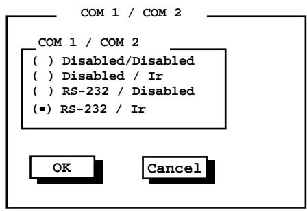
The default setting is RS - 232 / Ir .
Ir Mode
The "Ir Mode" item sets the communications compatibility mode for the IR port. When this item is selected, the submenu will display as shown below.
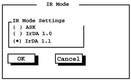
Select according to the type of device with which the notebook is to communicate.
The default setting is IrDA1.1.
NOTE: You cannot use the IrDA 1.1 and ECP functions at the same time. The IrDA 1.1 option will not appear in the submenu if the "LPT Extended Mode" item is set to ECP.
LPT Port
The "LPT Port" item sets the address for the LPT port (parallel port).
When this item is selected, the submenu displays as shown below.
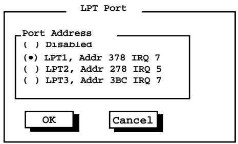
The default setting is LPT1.
LPT Extended Mode
The "LPT Extended Mode" item sets the LPT (parallel port) mode. Your system supports EPP (Enhanced Parallel Port) and ECP (Extended Capabilities Port) standards which turn the standard parallel port into a high speed bi-directional peripheral port.
When this item is selected, the submenu will display as shown below. Select the mode supported by the parallel device you are using.
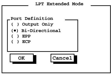
The default setting is Bi-Directional.
NOTE: You cannot use the IrDA 1.1 and ECP functions at the same time. The ECP option will not appear in the submenu if the "Ir Mode" item is set to IrDA 1.1.
SaveToDisk Warning Message
The "SaveToDisk Warning Message" item sets if the warning message will appear after system power on when there is no Suspend-to-Disk partition on the hard disk.
When this item is selected, no submenu will display. A check mark () indicates Enabled; an underline (_) indicates Disabled.
The default setting is Enabled.
Keyboard Numlock
The "Keyboard Numlock" item sets if the numeric keypad will function.
NOTE: If you disable this option, the numeric keypad on the notebook keyboard will not function even if the Num Lock indicator is on. However, an externally-connected keyboard is not affected by this feature.
When this item is selected, no submenu will display. A check mark () indicates Enabled; an underline (_) indicates Disabled.
The default setting is Enabled.
Pointing Device (PS/2 Mouse)
The "Pointing Device (PS/2 Mouse)" item enables or disables the built-in touchpad and track point, as well as the external PS/2 mouse.
When this item is selected, no submenu will display. A check mark () indicates Enabled; an underline (_) indicates Disabled. Disable this option if you are using a serial mouse.
Hot Key Beep
The "Hot Key Beep" item enables or disables the beep sound when hot keys are pressed.
When this item is selected, no submenu will display. A check mark () indicates Enabled; an underline (_) indicates Disabled.
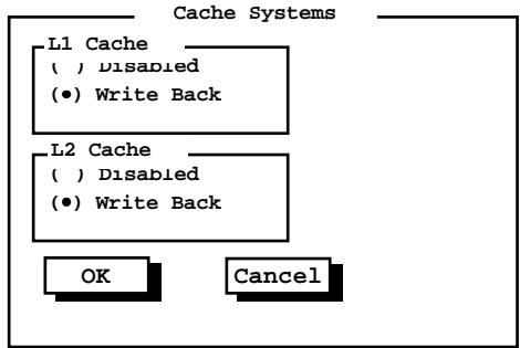
Cache Systems
The "Cache Systems" item enables or disables the cache of your system: L1 cache (internal cache of CPU) and L2 cache (external cache). The cache feature enhances system performance because the most frequently-used data is accessed from and written to the high-speed cache memory.
When this item is selected, the submenu will display as shown below.
Resolution Expansion
The "Resolution Expansion" item, when enabled, allows the display resolution to expand and occupy the whole LCD panel.
When this item is selected, no submenu will display. A check mark () indicates Enabled, an underline (_) indicates Disabled.
The default setting is Enabled.
Security Menu
The Security pull-down menu, as shown below, contains the Security settings which safeguard your system against unauthorized use.
Security
The followings describe in sequence all the items of the Security menu.
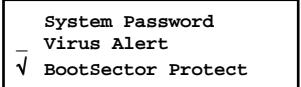
System Password
The "System Password" item allows you to set the password for your system. The password is required for starting up the system and running the SCU program.
When the item is selected, the submenu will display as shown below. When setting a password, first make sure that Num Lock is off, then type your password in the entry field and press [Enter]. Confirm your password by typing it again and pressing [Enter].
For the password to take effect, enable the "Enable Password" item.
System Password
Enter old Power-On Password:
Enter new Power-On Password:
Verify new Power-On Password: ....
[] Enable Password


Virus Alert
The "Virus Alert" item, when enabled, gives warning messages if the hard disk boot sector (partition table) has been changed.
When this item is selected, no submenu will display. A check mark () indicates Enabled, an underline (_) indicates Disabled.
The default setting is Disabled.
BootSector Protect
The "BootSector Protect" item helps prevent computer viruses by protecting the hard disk boot sector (partition table) from any change.
When this item is selected, no submenu will display. A check mark () indicates Enabled, an underline (_) indicates Disabled.
The default setting is Disabled.
CAUTION: Disable this item before installing an operating system, running Fdisk or Format program. Otherwise, the intended action will fail.
Power Menu
The Power pull-down menu, as shown below, contains the Power Management settings which help save power.
Power
| √ Enable Power Management |
| _ Max Performance √ Balanced Power Saving _ Max Power Saving _ Customize |
| Intel(R) SpeedStep(TM) Tech. |
The followings describe in sequence all the items of the Power menu.
Enable Power Management
The "Enable Power Management" item is the master control for the Power Management features.
When this item is selected, no submenu will display. A check mark () indicates Enabled; an underline (_) indicates Disabled.
The default setting is Enabled.
Max Performance / Balanced Power Saving / Max Power Saving / Customize
These four items are mutually-exclusive options. You can select one of them. A check mark () indicates Enabled; an underline (_) indicates Disabled. Descriptions of the four options are:
Options
| Max Performance | Select this option for the pre-defined settings which allow maximum performance but shortest battery life. |
| Balanced Power Saving | Select this option for the pre-defined settings which allow moderate performance and moderate battery life. |
| Max Power Saving | Select this option for the pre-defined settings which allow longest battery life but minimum performance. NOTE: To know the pre-defined settings for the above three options, you can select the next option to view the settings in the submenu. |
| Customize | Select this option for setting up your own preferences. When this option is selected, a |
Customizing Power Management Features
To customize Power Management features, select "Customize" from the Power pull-down menu. The submenu will display as shown below.
Customize
| Hard Disk Power Down After: | 2 Min |
| Idle Mode: | Enabled |
| Standby After: | 1 Min |
| Suspend After: | Disabled |
| Suspend Data to: | RAM |
| Cover Close: | Suspend |
| Battery Low Warning Beep: | Enabled |
| VGA Activity: | Disabled |
| Resume On Time: | Disabled |
| Hour | 0 |
| Minute | 0 |
| Second | 0 |
| Resume On Modem Ring: | Enabled |
| OK | Cancel |
The followings describe in sequence all the items of this submenu.
Hard Disk Power Down After
The "Hard Disk Power Down After" item sets the time-out period for the hard disk to power down if it is not in use during the set period. The hard disk will power up again when next accessed.
The available options are Disabled, 1 Min, 2 Min, 4 Min, 8 Min, 10 Min, 15 Min, and 20 Min.
Idle Mode
The "Idle Mode" item enables or disables Idle mode. If Idle mode is enabled, the CPU will speed down when the system has been idle for a brief period of time. The CPU will operate at full speed again when system activity is detected.
The available options are Enabled and Disabled.
Standby After
The "Standby After" item sets the time-out period for initiating Standby mode. It works in conjunction with the previous item "Idle Mode." After the notebook enters Idle mode, the Power Saving starts the time-out for the Standby mode. If the notebook remains in Idle mode until the time-out period for Standby mode has been reached, the notebook enters Standby mode.
If Standby mode is in effect, several system subsystems go into standby or off mode so that system power will be reduced. The system will wake up from Standby mode when system activity is detected.
The available options are Disabled, 1 Min, 2 Min, 4 Min, 6 Min, 8 Min, 12 Min, and 16 Min.
Suspend After
The "Suspend After" item sets the time-out period for initiating Suspend mode. It works in conjunction with the previous item "Standby After." After the notebook enters Standby mode, the Power Saving starts the time-out for the Suspend mode. If the notebook remains in Standby mode until the time-out period for Suspend mode has been reached, the notebook enters Suspend mode.
The Suspend mode is determined by the next item, "Suspend Data to." It can be either Suspend-to-RAM or Suspend-to-Disk.
When Suspend-to-RAM mode is initiated, several system subsystems go into standby or off mode so that system power will be reduced further. The system will wake up from Suspend-to-RAM mode when a key is pressed. "Resume On Time" and "Resume On Modem Ring", if enabled in this submenu, can also wake up the system from Suspend-to-RAM mode.
When Suspend-to-Disk mode is initiated, the system preserves all the running application programs as a file in a "suspend-to-disk partition" on the hard disk and then turns off automatically.
The available options are Disabled, 1 Min, 2 Min, 5 Min, 10 Min, and 15 Min.
Suspend Data to
The "Suspend Data to" item defines the Suspend mode of your system.
The available options are RAM and Disk.
Cover Close
The "Cover Close" item sets the notebook status when you close the cover.
Descriptions of the available options are:
Options
Video Off
CRT Display
Suspend
Descriptions
The LCD screen will be off when you close the cover.
The display output will switch to the external CRT monitor.
Either Suspend-to-RAM or Suspend-to-Disk is initiated
depending on the setting of the previous item, "Suspend Data to".
Battery Low Warning Beep
The "Battery Low Warning Beep" item enables or disables the low battery warning beep.
The available options are Enabled and Disabled.
VGA Activity
The "VGA Activity" item sets if obvious video activities (such as screen savers) will prevent Power Management modes.
Descriptions of the available options are:
Options
Descriptions
Enabled Power Management will not take effect if there are VGA
activities
Disabled Power Management will ignore VGA activities.
Resume On Time
The "Resume On Time" item enables or disables the system's waking up from Suspend-to-RAM mode at a time specified by the next three items.
The available options are Enabled and Disabled. If you select Enabled, set the time for the next three items.
Hour/Minute/Second
The "Hour", "Minute", and "Second" items work in conjunction with the previous item "Resume On Time." It sets the alarm time for waking up the system from Suspend-to-RAM mode.
Enter the value in each field by typing the number.
Resume On Modem Ring
The "Resume on Modem Ring" item enables or disables the system's waking up from Suspend-to-RAM mode when the modem receives an incoming call.
The available options are Enabled and Disabled.
Intel® SpeedStep™ Tech.
This option takes advantage of Intel's Geyserville technology, which can reduce the power consumption of CPU.
When this item is selected, thesubmenu will display as shown below.
Intel(R) SpeedStep(TM) Tech.
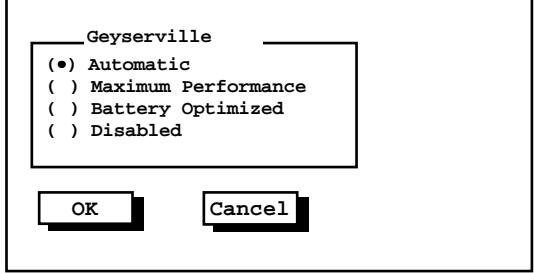
The default setting is Automatic.
NOTE: This menu item will not appear if the CPU does not support Geyserville feature.
Exit Menu
The Exit pull-down menu, as shown below, displays ways of exiting SCU. After finished with your settings, you must save and exit SCU so that the settings can take effect.
Exit
Save Change and Exit
Discard Changes and Exit
Get Default Values
Load Previous Values
Descriptions of the Exit choices are:
Choices
Save Change and Exit Discard Changes & Exit
Get Default Values Load Previous Values
Descriptions
Save changes you have made and exit. Exit without saving the changes you have made.
Load factory default values for all the items. Restore previous values for all the items.
Chapter 6
Software Drivers and Utilities
This chapter tells users how to install required drivers and useful programs for Windows 95, 98 and NT system. Descriptions of all available options are also provided, so that you can utilize the feature functions of your notebook.
NOTE:
- The CD may have been updated after this manual was published.
- README files can always be found on the CD. It is advised that you see these files together with this manual.
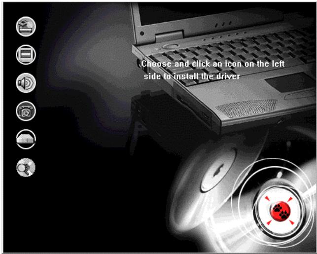
How to Use the CD
A SETUP program is provided on the CD. To run the program, simply insert the CD and it will automatically start. If you need to start the program manually, specify the file "Setup.exe" under \Setup directory. Then the main screen will appear:
NOTE:
- This CD supports Windows 98, Windows 95 OSR2 or above, and Windows NT Pack 3 or above. Other systems are not supported.
- The chipset driver must be installed first before any other driver is installed.
- The available items may differ according to your equipment and operation system. (i.e. You may not be able to see all the items listed below.)
To setup the intended driver, just click on the according icon and the installation will start. The functions of the items are described as the followings:

Chipset Driver
Install this driver first.
The chipset driver is provided for your operation system to recognize the Intel 82443BX AGPset controller chip. By choosing this item, some drivers for other components, such as audio and IR devices, are also installed.
NOTE: If you need to install the audio driver manually, a "setup.exe" program can be found under \Audio\Crystal CS4280\WIN95&WIN98.

VGA Driver
The VGA driver allows you to select high-resolution displays with richer colors.

Software Wavetable
This option will enhance the capability of the sound subsystem. By using the software wavetable program, you can experience more realistic sound effects in the world of multimedia.

Modem Driver
If your notebook has the Fax/Modem/Voice card equipped, you need to install the modem driver before taking advantage of the function.

LAN Card Driver
If your notebook has the LAN Card equipped, you need to install this driver before taking advantage of the function.

PCMCIA Driver
The PCMCIA driver allows you to configure your PC card and enhance the functionality of the PC card technology.

Mouse/ Touchpad Driver
The mouse/touchpad driver allows you to take advantage of the touchpad device, as well as a standard mouse, if any is connected.

BUS Master
The Bus Master allows you to take advantage of the enhanced capabilities (such as 33MB/sec data transmission speed) of an Ultra-DMA hard disk.

Geyserville Driver
This driver allows your notebook to take advantage of Intel Geyserville technology, which can reduce CPU power consumption. Note that only Pentium III 500 or above will support this feature.

3 Mode FDD Driver
If you are a Japanese user, you need to install the 3 mode driver for accessing the NEC/Fujitsu/Toshiba 1.2MB diskettes.
NOTE: Before installation, make sure the 3 mode driver for DOS does not exist in your hard disk.

Power-Profiler Utility
For Windows NT only.
PowerProfiler provides a complete power management solution for notebook computers running Windows NT 4.0. PowerProfiler also offers suspend/resume control, active battery status and metering, and a wide variety of user selectable parameters and alarms all within an easy-to-use Windows application.

Explore the CD
Choose this option if you like to explore the content of the CD and search the drivers by yourself.
Other Drivers and Utilities
0VMAKFIL Utility
CAUTION: Check with your dealer to find out if the suspend-to-disk partition is already created. If it is not created and you want to create the partition by yourself, make sure that your hard disk is empty. That is, your hard disk is not yet partitioned by the FDISK program. If any partition exists, you have to use the FDISK program to delete all partitions before you can use the 0VMAKFIL utility.
The 0VMAKFIL.EXE utility program allows you to create the suspend-to-disk partition in your hard disk, which is required for the Suspend-to-Disk function of your notebook. To utilize the program, you can either locate the file under the \S2D directory on the CD, or you can create a diskette containing the 0VMAKFIL.EXE file and CD-ROM (or DVD-ROM) drivers. Follow these steps to create the diskette:
- When booting up, press [F2] to enter the BIOS setup screen.
- In the pull-down Main Menu, choose "Boot Sequence" item. In the subsequent menu, select "CD-ROM then C:" option.
- Insert the CD, save change and reboot the system.
- Insert a formatted diskette into the floppy drive. After the system boots from the CD-ROM, the setup program will copy all necessary files onto the diskette.
- After the process is finished, the system will reboot. When booting up, press [F2] again and change the "Boot Sequence" option from "CD-ROM then C:" to other items. Save the change and restart the system.
- Now you can run the 0VMAKFIL program under the \S2D directory on the diskette, following this command syntax:
0VMAKFIL-Pnn
where nn specifies the size (in MB) of the partition.
You can have the size larger than your current system memory size for future upgrade of your memory. If you do not specify the parameter, the default size will be your system RAM plus 2MB. The extra 2MB is for the overhead of the program and data held in video memory.
You can clear the contents of the partition using the 0VMAKFIL -C command. The command is useful only when you are backing up the data in the hard disk drive.
Installing the CD-ROM/DVD-ROM Driver for DOS
If you need to use the CD-ROM or DVD-ROM drive under DOS system, you must install the appropriate driver to make it functional. Before installation, you must create a diskette containing the CD-ROM (or DVD-ROM) drivers. Please refer to the preceding section step 1~5 to see how to create such a diskette.
If your notebook is equipped with a CD-ROM drive, you will find a CD-ROM directory on the diskette. Please read the "Readme.txt" file in the directory to see the installation procedures.
If your notebook is equipped with a DVD-ROM drive, you will find a DVD-ROM directory on the diskette. Please run the "Setup.exe" file in the directory and follow the on-screen instructions to install the driver.
Installing the Japanese Floppy Driver for DOS
If you are a Japanese user, you need to install the 3 mode driver for accessing the NEC/Fujitsu/Toshiba 1.2MB diskettes.
NOTE: Before installation, make sure the 3 mode driver for Windows series system does not exist in your hard disk.
All the files are located in the 3m_fdd\Dos directory on the CD. For installation instructions, see the "Readme.txt" file under the directory.
Installing the PCMCIA Driver for DOS
If you are using PC Cards under DOS, you must install this driver.
All the files are located in the \PCMCIA\CardWorks\Dos\English directory on the CD. Please run the "Install.exe" file in the directory and follow the on-screen instructions to install the driver.
Appendix A
Specifications
NOTE: The specifications are subject to change without notice.
CPU, Memory, and Main Components
CPU
Intel Pentium III or Celeron series CPU
Note: For the latest information on the CPU supported by your notebook, please consult your dealer.
RAM
Expandable to 256MB (depending on the availability of SO-DIMM module)
- Cache Memory
128/256/512KB on-die or L2 module cache memory (depending on CPU types), with support for "stop clock" mode
ROM BIOS
256KB Flash EEPROM, supporting boot block, video, security, setup, and power management
LCD Display
14.1-inch TFT XGA (1024 x 768) color LCD, integrated power conservation mode
Notebook Keyboard
86 keys, numeric keypad, 12 function keys, a special Fn (Function) key and Windows 95 keys
- Floppy Disk Drive
3.5-inch, 135TPI, double sided, total formatted capacity 1.44MB, with 3 mode 1.2MB support
Hard Disk Drive
Enhanced-IDE, 2.5-inch, 4.3GB or other capacity when available
CD-ROM Drive
ATAPI IDE 24X CD-ROM
- Touchpad
Compatible with PS/2 mouse
Real-Time Clock/Calendar
128 Bytes, providing system clock, calendar, and configuration information, stored in CMOS RAM, with battery backup
Interfaces and Controllers
VGA Controller
High performance flat panel CRT/LCD VGA controller, supports TFT/DSTN LCD panel, interfaced at 32-bit PCI-bus, up to 1600 x 1200 x 16M on an external CRT monitor
- Parallel Port
Standard/ECP/EPP parallel communication interface with a DB-25 female connector
Serial Ports
COM1 and COM2 assigned to two of the followings:
- RS-232C communication interface with a 9-pin D-type shell connector
- Fax/Modem Card option
- IrDA 1.0/IrDA 1.1/ASK communication interface
Auxiliary Device Port
A 6-pin miniature DIN connector for a PS/2-compatible keyboard or mouse
PC Card Slots
Compliant with PCMCIA 2.1/JEIDA 4.1 specifications along with ExCA extension and PC CARD standard, two PC card slots for two type II application, supporting CardBus and Zoomed Video port
Audio Subsystem
Supports 3D sound and wavetable capacity, fully compatible with MS Windows Sound System, legacy compatible with DOS sound system
Power Source
AC Adapter
Switched power supply with a separate AC power cord; full range voltage between 100V~240V; frequency 50~60Hz
Output voltage DC 19V, with overcurrent and overcharging protection
Battery Pack
NiMH, 9 cells, 4/3 A type, 1.0~1.45V per cell
Li-ion, 9 cells, 4/3 A type, 3.6V per cell
Environmental Specifications
| Temperature Range | Relative Humidity | |
| Operating | 100C (500F) to 350C (950F) | 20% to 80% non-condensing |
| Storage | 00C (320F) to 600C (1400F) | 10% to 90% non-condensing |
Appendix B
Troubleshooting
This appendix is designed to help you find and solve minor problems that you may encounter using the notebook.
Troubleshooting Approach
The problems that you might encounter can be divided into two basic categories: hardware and software. Hardware problems can be further divided into being of an electrical or a mechanical nature. You will know you have a hardware problem if, for example, the screen is blank, the notebook cannot recognize the disk drives, or you get an error message during the Power-On Self Test (POST).
Software problems can occur at several levels. Both your operating system and your software application programs are capable of generating errors and error messages. If you encounter a software error, try to determine if the error message is from your operating system or from an application program, and refer to the appropriate manual for possible remedies.
If you still have a problem after trying all the suggested remedies in this appendix, contact your dealer.
Common Problems
When you encounter a problem, begin by performing a careful visual inspection. Check the exterior of the notebook first. If no indicators are on, check the battery charge or electrical outlet, the plug and power cord, and any power switches that may affect your notebook. If the notebook has been connected to any peripheral devices, look for loose or disconnected cables.
A few common problems and suggested solutions are presented in the examples which follow.
Problem: The power button does not function.
The power button does not respond to a light touch. Press the button firmly.
- If you are using battery power, the battery may be discharged. Connect the AC adapter.
Problem: The screen is blank.
- Press the Spacebar to see if any power management feature has blanked the screen to save power.
- If the AC Power Indicator is not on, check the electrical outlet, the plugs and power cords.
- If you are using a battery pack, make sure it has a charge remaining, and that it is installed correctly.
- Check the brightness and contrast controls for your display.
- Reset the notebook by pressing the [Ctrl] + [Alt] + [Delete] keys.
- Turn the notebook off, wait a few seconds, and then turn the notebook back on.
Problem: Bad pixels appear on the LCD screen.
- Because of limitations of the LCD technology, bad pixels may appear on the screen. The inspection standard generally agreed in the LCD industry allows a maximum of 8 bad pixels on an unit.
Problem: The floppy disk drive cannot read or write a diskette.
The diskette is not yet formatted, or could be corrupted.
- If you can't write to a diskette, the diskette may be write-protected. Check to ensure that the write-protect tab covers the detection hole.
If you can't write to a diskette, the diskette may be full. Use another diskette.
Problem: The message "non-system disk" or "disk error" appears on the screen after you turn on the system.
- You may have inserted a non-bootable diskette in the floppy disk drive. Remove the diskette.
- Check the SCU program to ensure that the drive types are correctly identified.
- If this message is issued when you attempt to boot from your hard disk drive, insert a bootable diskette and check the integrity of your hard disk drive.
Problem: The date and/or time is incorrect.
- Correct the date and time using the SCU program or your operating system.
- If the date and time are still incorrect, it can be that the RTC battery is discharged after the notebook has not been used for a very long time. If so, connect the AC adapter to charge the RTC battery for 8 hours and then keep the notebook power off for one hour. Then run the SCU program to reconfigure the system.
Problem: The battery cannot be fully recharged.
- For safety reasons, several factors can stop the recharging, e.g., when the battery's temperature gets above 40^ ( 104^ ) or the recharging time exceeds 4 hours. To avoid problems caused by the temperature factor, make sure the battery does not get too hot. To avoid problems caused by the time factor, you are advised to keep the notebook power off during recharging. If you use the notebook during recharging for more than 4 hours, the recharging will stop no matter whether the battery has been fully recharged or not. If this happens, you
B-2
Troubleshooting
can disconnect and then reconnect the AC adapter to start the recharging again.
Problem: The battery cannot be recharged.
- Recharging will not start if the battery's temperature is below 0^ ( 32^ ) or above 40^ ( 104^ ). Make sure the battery's temperature is within the range.
Problem: The PC Card which uses the COM interface does not function.
- The card may be attempting to use COM3 or COM4 ports in a manner that conflicts with the COM1 or COM2 port being used by another device. You may be able to resolve the conflict by running the SCU program to change the COM port settings. If your PC Card uses COM3, set the COM1 part of "COM Port" item to Disabled. If your PC Card uses COM4, set the COM2 part of the "COM Port" item to Disabled.
Problem: No sound is produced.
- Confirm the audio driver is installed.
- Check if software-dependent volume control is set too low.
Problem: Distorted sound is produced.
- Ensure the volume control is not set too high or too low. In most cases, high settings can cause the audio electronics to distort the sound.
Problem: Bad pixels on the LCD screen.
- The following is a table of LCD pixel inspection standard, which can offer you the necessary information to examine the LCD screen. Any condition that does not violate the standard is considered to be normal.
Term definitions:
Bright dots: When the LCD screen is lighted, dots appear bright at dark area. Red/green/blue bright dots also count.
Dark dots: When the LCD screen is lighted, dots appear black at bright area.
Distance between defective dots: The minimum distance between two defective dots.
Adjacent defective dots: Defective dots within a radius of 10mm
| LCD Type | Defective dots | Distance between defective dots | Two adjacent defective dots | Three or more adjacent defective dots | Total | ||||
| Bright | Dark | Bright | Dark | Bright | Dark | Bright | Dark | ||
| 12.1" SVGA | N≤5 | N≤5 | ≤15• | ≤15• | ≤2 Pairs | ≤2 Pairs | Not allow | Not allow | N≤8 |
| 13.3" XGA | N≤5 | N≤7 | ≤15• | ≤15• | ≤2 Pairs | ≤2 Pairs | Not allow | Not allow | N≤9 |
| 14.1" XGA | N≤5 | N≤7 | ≤15• | ≤15• | ≤2 Pairs | ≤2 Pairs | Not allow | Not allow | N≤9 |
| 15" XGA | N≤8 | N≤8 | <15• | <15• | ≤2 Pairs | <2 Pairs | Not allow | Not allow | N≤10 |
| 18" XGA | N≤9 | N≤15 | ≤5• | ≤20• | ≤3 Pairs | ≤5 Pairs | Not allow | Not allow | N≤20 |
Chapitre 1
Mise En Route
Scroll Lock indicator
Num Lock indicator
A Caps Lock indicator
Floppy disk drive in-gebruik indicator
Hard disk drive in-gebruik indicator
CD-ROM drive in-gebruik indicator
- Stroom indicators
Batterij indicator
Local Power Management
Setup Configuration Utility
Max Performance / Balanced Power Saving / Max Power Saving / Customize
Battery Low Warning Beep
Resume On Modem Ring
Discard Changes & Exit
Get Default Values
nstellingen. Load Previous items.